

Leybold vacuum RUVAC WS 251, RUVAC WS 2001, RUVAC WSU 251, RUVAC WS 1001, RUVAC WS 501 Operating Instructions Manual
...
RUVAC WS/WSU
251/501/1001/2001
Roots pump with mineral oil,
synthetic oil or PFPE filling
Cat.-No.
101 83
117 22/32/42/52
117 23/33/43/53
117 27/37/47/57
117 28/38
118 33/43/53
150 44/95/96
167 007
917 48
155 000
Operating Instructions
GA 03.108/14.02
Vacuum Solutions
Application Support
Service
LEYBOLD VACUUM

Contents
Contents
Page
IMPORTANT SAFETY CONSIDERATIONS . .4
1 Description . . . . . . . . . . . . . . . . . . . . . . . . . .6
1.1 Design and function . . . . . . . . . . . . . . . . . . . .6
1.2 Standard specification . . . . . . . . . . . . . . . . . .9
1.3 Technical data . . . . . . . . . . . . . . . . . . . . . . .10
1.4 Accessories . . . . . . . . . . . . . . . . . . . . . . . . .11
2 Transportation and storage . . . . . . . . . . . .12
3 Installation and connection . . . . . . . . . . . .13
3.1 Installation . . . . . . . . . . . . . . . . . . . . . . . . . .13
3.2 Filling in of the lubricants . . . . . . . . . . . . . . .13
3.3 Electrical connections . . . . . . . . . . . . . . . . . .14
3.4 Connection of the flanges . . . . . . . . . . . . . . .16
4 Operation . . . . . . . . . . . . . . . . . . . . . . . . . .17
4.1 Start-up . . . . . . . . . . . . . . . . . . . . . . . . . . . .17
4.2 Operation . . . . . . . . . . . . . . . . . . . . . . . . . . .17
4.3 Shutdown and storage . . . . . . . . . . . . . . . . .18
4.4 Changing from vertical to horizontal flow . . . .18
5 Maintenance . . . . . . . . . . . . . . . . . . . . . . . .19
5.1 Safety information . . . . . . . . . . . . . . . . . . . . .19
5.2 Exchanging the lubricants . . . . . . . . . . . . . . .19
5.3 Cleaning the fan cowl and the cooling fins . .20
5.4 Cleaning the dirt trap . . . . . . . . . . . . . . . . . .20
5.5 Cleaning the pumping chamber . . . . . . . . . .21
5.6 Cleaning the valve of the pressure
balance line . . . . . . . . . . . . . . . . . . . . . . . . .21
5.7 Leybold service . . . . . . . . . . . . . . . . . . . . . .22
6 Troubleshooting . . . . . . . . . . . . . . . . . . . . .23
EEC Declaration of Conformity . . . . . . . . .24
Indicates procedures that must be strictly
observed to prevent hazards to persons.
Indicates procedures that must strictly be
observed to prevent damage to, or destruction of the equipment.
Figures
The references to figures, e.g. (1/2) consist of the Fig.
No. and the Item No. in that order.
2
GA 03.108/14.02 - 01/03
Warning
Caution

Contents
Leybold-Service
If a pump is returned to Leybold, indicate whether the
pump free of substances damaging to health or whether
it is contaminated.
If it is contaminated also indicate the nature of the
hazard. Leybold must return any pumps without a
„Declaration of Contamination“ to the sender’s address.
Disposal of waste oil
Under the amended law relating to waste disposal dated
November 1, 1986 (valid in the Federal Republic of Germany) the disposal of used oil is subject to new provisions. According to legislation relating to waste disposal
the so-called principle of causality is applied. Hence,
anyone in possession of used oil is responsible for its
proper disposal.
Used oils coming from vacuum pumps must not be
mixed with other substances.
Used oils from vacuum pumps (LH-oils on the basis of
mineral oils) having been affected by normal contamination due to oxygen from the ambient air, increases in
temperature and mechanical wear, must be disposed of
as used oil in accordance with the regulations.
Used oils from vacuum pumps that have been contaminated by other substances must be labelled, stored and
disposed of as special waste with reference to the kind
of contamination.
If you send a pump to LEYBOLD for repair please indicate any harmful substances existing in the pump oil or
around the pump.
When disposing of used oil please observe the safety
regulations that are valid in your country.
We reserve the right to modify the design and the specified data. The illustrations are not binding.
3
GA 03.108/14.02 - 01/03
4
GA 03.108/14.02 - 01/03
Safety considerations
IMPORTANT SAFETY CONSIDERATIONS
The Leybold RUVAC vacuum pump is designed for safe and efficient operation when used properly and
in accordance with this manual. It is the responsibility of the user to carefully read and strictly observe
all safety precautions described in this section and throughout the manual. This product must be operated and maintained by trained personnel only. Consult local, state, and national agencies regarding
specific requirements and regulations. Address any further safety, operation and/or maintenance questions to your nearest Leybold Vacuum office.
Warning
Failure to observe the following precautions could result in serious personal injury.
• Before beginning with any maintenance or service work on the RUVAC, disconnect
the pump from all power supplies.
• Do not operate the pump with any of the covers removed. Serious injury may result.
• If exhaust gases must be collected or contained, do not allow the exhaust line to
become pressurized.
• Make sure that the gas flow from the exhaust port is not blocked or restricted in
any way.
• The standard version of the RUVAC is not suited for operation in explosion hazard
areas. Contact us before planning to use the pump under such circumstances.
• Before starting up for the first time, the motor circuit must be equipped with a suitable
protective motor switch. Please take note of the information in these Operating
Instructions or on the electric motor (wiring diagram).
• The RUVAC is not suited for pumping of
- combustible and explosive gases or vapours
- radioactive and toxic substances
- pyrophorous substances.
• The RUVAC must be integrated in the system control arrangement so that the pump
can not run-up automatically after it has been shut down by the temperature switches
in the motor. This applies equally to emergency shut-down arrangements. After having
determined the fault cause, the pump should be switched on manually again.
• Avoid exposing any part of the human body to the vacuum.
• Never operate the RUVAC without a connected intake line or blank flange.
• The location at which the RUVAC (including its accessories) is operated should be
such that angles over 10° from the vertical are avoided.
• The location of the RUVAC should be such that all controls are easily accessible.
• Under certain ambient conditions the RUVAC may attain a temperature of over 80 °C
(176 °F). There then exists the danger of receiving burns.
Note the symbols on the pump pointing to the hazards, and in the case of a hot pump
wear the required protective clothing.

5
GA 03.108/14.02 - 01/03
Safety considerations
Warning
• The noise level produced by the RUVAC is about 63 to 72 dB(A).
Make sure that suitable protection measures are taken to protect the hearing.
• Before pumping oxygen (or other highly reactive gases) at concentrations exceeding the
concentration in the atmosphere (> 21 % for oxygen) it will be necessary to use a special pump.
Such a pump will have to be modified and de-greased, and an inert special lubricant (like PFPE)
must be used.
• Before commissioning the RUVAC, make sure that the media which are to be pumped are
compatible with each other so as to avoid hazardous situations.
All relevant safety standards and regulations must be observed.
• It is recommended to always operate the RUVAC with a suitable exhaust line which is properly
connected.
• When moving the RUVAC always use the allowed means.
A lifting eye is provided as standard on the pump.
Caution
Failure to observe the following precautions could result in damage to the pump:
• Do not allow the ingestion of small objects (screws, nuts, washers, pieces of wire, etc.)
through the inlet port. Always use the screen which is supplied with every pump.
•Do not use the pump for applications that produce abrasive or adhesive powders or
condensable vapors that can leave adhesive or high viscosity deposits. Please contact Leybold Sales
for selecting the right separator.
• Before pumping vapors, the RUVAC should have attained its operating temperature.
The pump will have attained its operating temperature about 30 minutes after starting the pump.
During this time the pump should be separated from the process, by a valve in the intake line,
for example.
• In the case of wet processes we recommend the installation of liquid separators upstream and
downstream of the pump so as to avoid a massive influx of liquid into the pump.
• The exhaust line should be laid so that it slopes down and away from the pump so as to prevent
condensate from backstreaming into the pump.
• In order to prevent the transfer of vibrations from the RUVAC to other parts of the system we
recommend the use of corrugated hoses or compensators on both the intake and the exhaust sides.
• The entry of particles and fluids must be avoided under all circumstances.
• Corrosion, deposits and cracking of oil within the pump are not allowed.
Description
6
GA 03.108/14.02 - 01/03
1 Description
1.1 Design and Function
The RUVAC WS and RUVAC WSU are Roots pumps driven by a canned motor.
The WSU types have a pressure balance line between
the discharge and intake flanges.
The RUVAC WS and WSU are lubricated with mineral oil
or perfluorized polyether (PFPE) in the case of the PFPE
models. Apart from the lubricant the mineral oil and
PFPE models are identical in type.
Only the RUVAC WS/WSU PFPE can be used for pumping greater than atmospheric concentrations of oxygen
or very aggressive or hazardous gases.
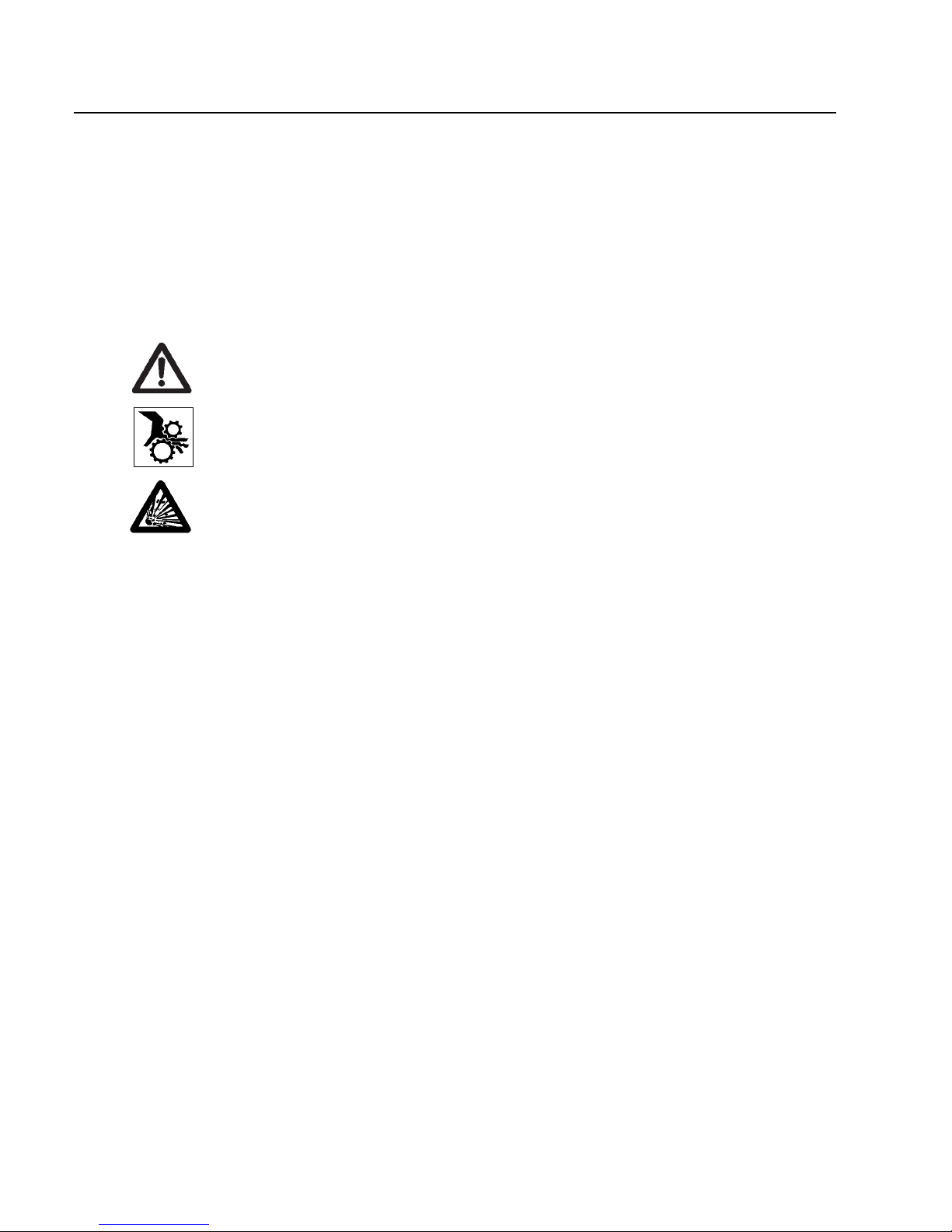
1.1.1 Principle of Operation
Roots pumps - also known as Roots blowers - contain in
their pump casing (1/3) two symmetrical impellers (1/4)
rotating in opposite directions. The impellers have roughly the cross section of a figure „8“ and are synchronised
by a toothed gearing so that they move past each other
and the casing without contact but with a small clearance.
The principle of operation is explained in Fig. 2.
In impeller positions I and II, the volume in the intake
flange is increased. When the impellers rotate further to
position III, part of the volume is sealed off from the intake side.
In position IV, this volume is opened to the discharge
side, and gas at backing pressure (higher than the intake pressure) flows in. The inflowing gas compresses the
gas volume pumped from the intake side. As the impellers rotate further, the compressed gas is ejected via the
discharge flange.
This process occurs twice per complete revolution of
each of the two impellers.
Due to the non-contacting rotation in the pumping chamber, Roots pumps can be operated at high speeds (standard n = 3,000 rpm at a mains frequency of 50 Hz). Thus
a relatively high pumping speed is attained with small
pumps.
The pressure differential and compression ratio between
the intake and discharge sides are limited on Roots
pumps. If the allowable pressure differential is exceeded,
the pump overheats.
In practice, the maximum attainable pressure differential
is significant only in the rough vacuum range (p > 10
mbar), whereas for pressures in the fine vacuum range
(p < 1 mbar) the attainable compression ratio is decisive.
Fig. 2 Functional diagram of a Roots pump (vertical flow)
1
2
3
4
5
Key to Fig. 1
1 Intake flange
2 Pumping chamber
3 Casing
4 Impeller
5 Discharge flange
Fig. 1 Schematic cross-section of a Roots pump (vertical flow)
Description
7
GA 03.108/14.02 - 01/03
RUVAC pumps from the WS/WSU range have been specifically designed for operation in the rough and fine
vacuum ranges. They are thus either used in connection
with backing pumps or in closed gas cycles. The pump’s
power consumption depends not only on the pumping
chamber volume and the rotational speed of the pump,
but also on the pressure differential between the discharge and intake flanges (see Fig. 7).
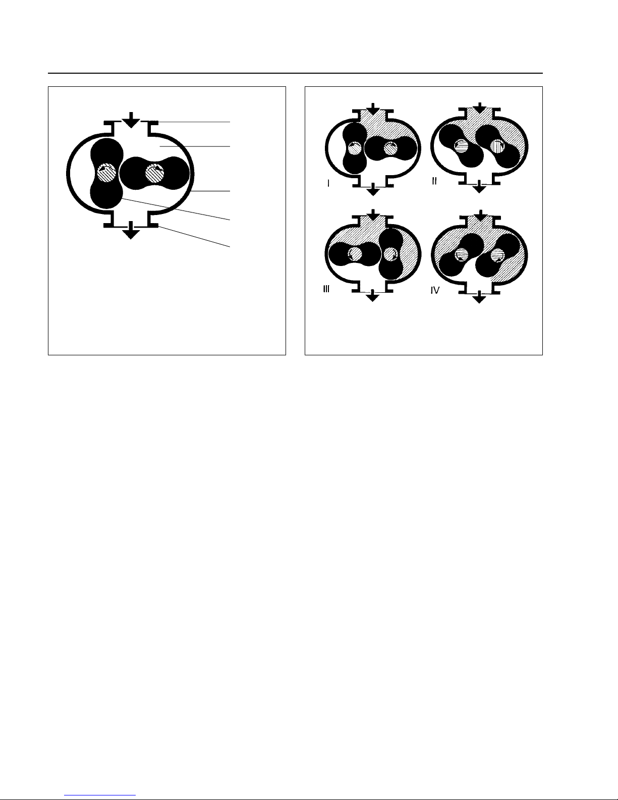
1.1.2 Design
RUVAC Roots pumps can pump gas in the vertical or
horizontal direction.
Although the pumping chamber of Roots pumps is free
of sealing agents and lubricants, the two gearwheels of
the synchromesh gearing (3/1) and the bearings (3/2)
are lubricated with mineral oil or with PFPE. The gearwheels and bearings of the RUVAC are located in two
side chambers which also contain the oil supply.
These two side chambers are separated from the pumping chamber by the impeller seals (3/3). During operation of the pump, the side chambers are evacuated via the
impeller seals.
The side chambers are linked to each other by two passages (3/12). These passages are arranged so that for
either horizontal or vertical flow the pressure will be
equalised between the oil supplies.
In both side chambers there are integrated oil pumps to
ensure that the bearings and gearwheels receive sufficient lubricant at all recommended speeds.
RUVAC WS/WSUs are driven by a canned motor. In such
a motor, the rotor and stator coils (3/6) are separated by
a vacuum-tight can (3/7) made of non-magnetic material. The rotor runs in the vacuum on the pump’s drive
shaft (3/10); thus a shaft feedthrough to the atmosphere
is not needed.
With the standard motors, the RUVAC WS/WSUs can
run on either 50 Hz or 60 Hz power supplies.
For the permissible electrical connection data with respect to these frequencies, see Section 1.3.
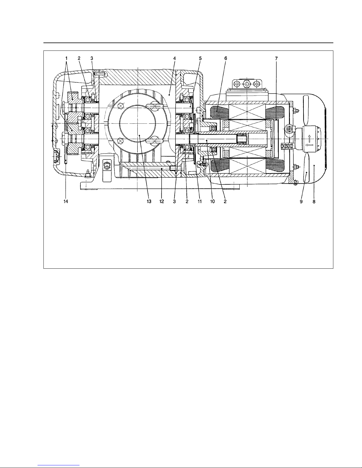
Fig. 3 Longitudinal section of a RUVAC WS 1001 (horizontal flow)
Key to Fig. 3
1 Gearwheels 8 Fan cowl
2 Bearings 9 Fan
3 Impeller seals 10 Drive shaft
4 Impellers 11 Centrifugal disc lubricator
5 Driven impeller shaft 12 Equalisation passage
6 Stator 13 Intake port
7 Can 14 Centrifugal disc lubricator
Description
8
GA 03.108/14.02 - 01/03
Incorporated in the motor’s stator winding is a thermal
switch which turns off the pump when the motor temperature is too high.
RUVAC WS/WSUs are air-cooled. The airflow for cooling
the motor and pump is produced by a fan (3/9) with its
own drive motor under the motor’s fan cowl (3/8).
When operating the pump via a frequency
converter you must ensure that the drive
motor for the fan is connected to the mains.
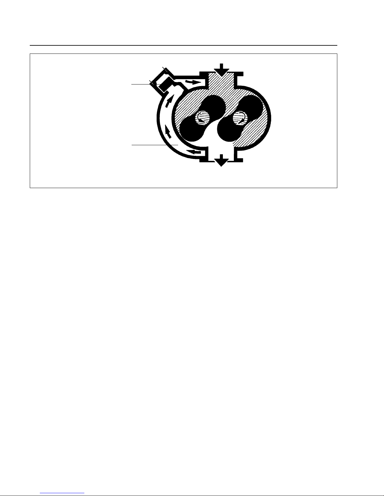
1.1.3 Pressure Balance Line
The RUVAC WSU has an integrated pressure balance
line (4/1). It links the discharge and intake flanges via a
pressure balance valve.
If the pressure differential between the flanges is too
large, the valve opens (4/2). Some of the gas which has
already been pumped then flows back through the line to
the intake flange.
The valve is weight- and spring-loaded so that it works
with both vertical and horizontal flow of the pump.
As a result of this pressure balance line, no additional
devices are needed to protect the pump against excessive pressure differentials.The RUVAC WSU can be switched on at atmospheric pressure at the same time as a
backing pump. As a result, the pumping speed of the
pump combination is increased even at high intake pressures.
1.1.4 Lubricants
RUVAC WS/WSU pumps are, as standard, prepared either for operation with mineral oil, synthetic oil or the special lubricant perfluoropolyether PFPE).
Other types of oil (white oil, for example) upon request.
If mineral oil and PFPE come into contact
they will emulsify. That’s why the pumps
must only be run with the type of lubricant
specified for the pump. If you want to change the type of lubricant LEYBOLD should
do the change.
In case of operation with mineral oil we recommend our
vacuum pump oil N 62 (HE-200 in the USA). In case of
operation with PFPE we recommend our NC 1/14
(HE1600 in the USA).
PFPE pumps are marked by an additional red label at
the oil-fill screw.
The Operating Instructions GA 07.009 „PFPE for Vacuum Pumps“ will be enclosed with any RUVAC PFPE.
Observe the handling notes for PFPE collected in these
Operating Instructions.
1.1.5 Flange Connections
The cast flanges on the pump’s body comply with DIN
2501, nominal pressure 6.
The pumps are supplied with different collar flanges:
Pumps with Cat. Nos. beginning with 117... are equipped
with ISO-K collar flanges. This standard can be applied
in all other parts of the world.
Fig. 4 Schematic diagram of a Roots pump with pressure balance line
Caution
Key to Fig. 4
1 Pressure balance line
2 Pressure balance valve
2
1
Caution
 Loading...