

Leybold vacuum PhoeniXL300 Technical Handbook
echnical handbook
GA10.218_1.02
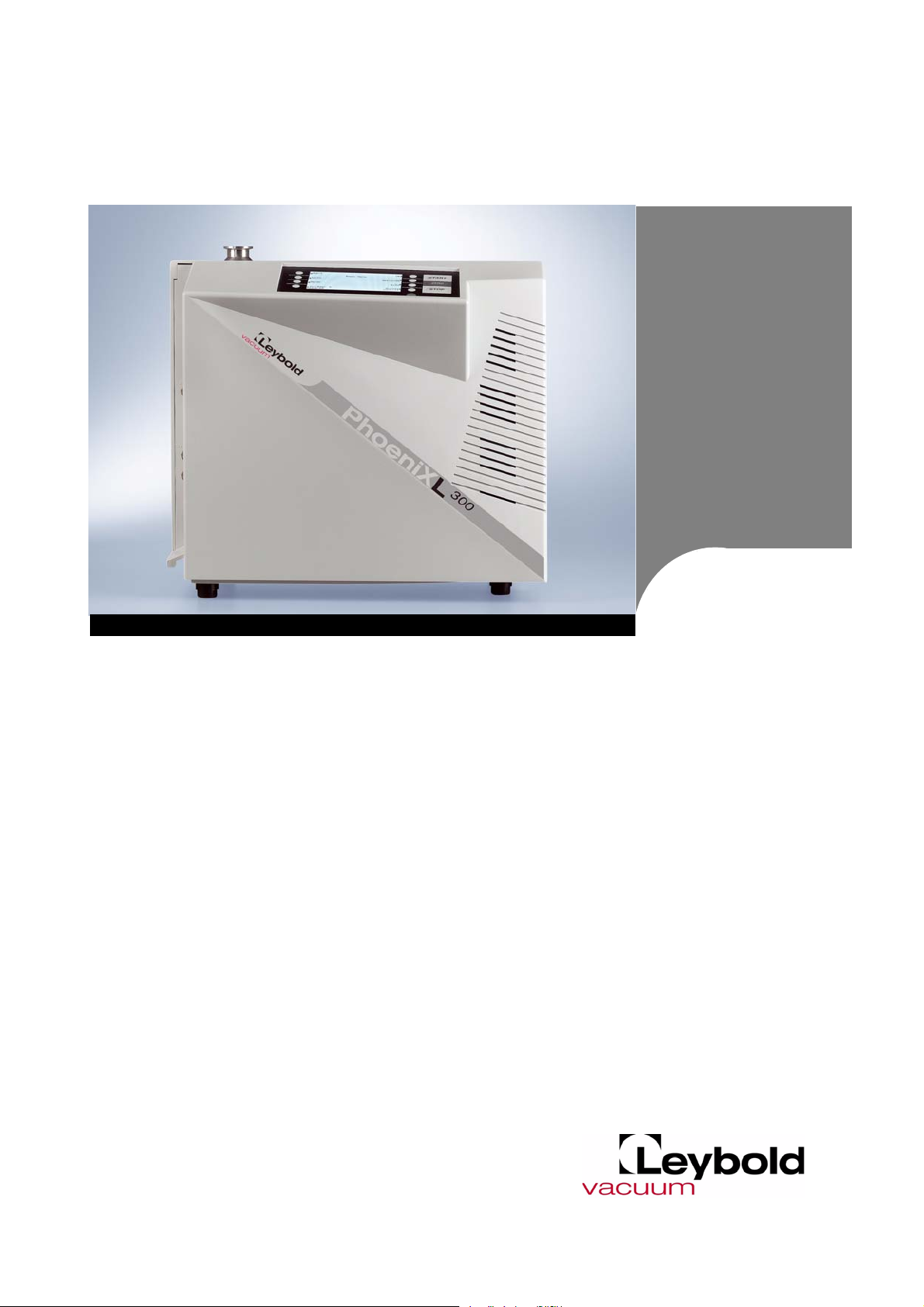
300
PhoeniXL
Leak detector
catalog-number
300
PhoeniXL
PhoeniXL
PhoeniXL
250000, 251000
300
dry 250001, 251001
300
Modul 250002

Content
Table of Contents
1 General Information ........................................................................................7
1.1 Notes on the Use of this Handbook .................................................................... 7
1.1.1 Safety Symbols .................................................................................................. 7
1.1.2 Indications .......................................................................................................... 7
1.1.3 Symbols of Vacuum Technology ........................................................................ 7
1.1.4 Definiton of Terms .............................................................................................. 8
1.2 Support from LEYBOLD Service ......................................................................... 9
1.3 Introduction ...................................................................................................... 10
1.3.1 Purpose ........................................................................................................... 10
1.3.2 Technical Data ................................................................................................. 11
1.3.2.1Physical Data PhoeniXL300 ....................................................................11
1.3.2.2Electrical Data ........................................................................................11
1.3.2.3Other Data ..............................................................................................12
1.3.2.4Ambient Conditions ................................................................................12
1.3.2.5Physical Data PhoeniXL300 dry ..............................................................12
1.3.2.6Electrical Data ........................................................................................13
1.3.2.7Other Data ..............................................................................................13
1.3.2.8Ambient Conditions ................................................................................13
1.3.2.9Physical Data PhoeniXL300 Modul .........................................................14
1.3.2.10Electrical Data ......................................................................................14
1.3.2.11Other Data ............................................................................................14
1.3.2.12Ambient Conditions ..............................................................................15
1.4 Unpacking ........................................................................................................ 16
1.4.1 Supplied Equipment ......................................................................................... 16
1.4.2 Accessories and Options .................................................................................. 16
1.4.2.1Sniffer line SL300 ...................................................................................16
1.4.2.2Hand set ................................................................................................17
2 Installation ......................................................................................................19
2.1 Working Location ............................................................................................. 19
2.2 Electrical Connections ...................................................................................... 19
2.2.1 Mains Power .................................................................................................... 19
2.2.2 Connections for the Data Acquisition Systems ................................................. 20
2.2.2.1Option (Accessories) ...............................................................................20
2.2.2.2Digital Out ..............................................................................................21
2.2.2.3Digital In .................................................................................................22
2.2.2.4Recorder ................................................................................................23
2.2.2.5RS232 ....................................................................................................24
2.2.2.6Hand Set ................................................................................................24
2
⏐
GA10.218_1.02 - 11/2004

Content
2.3 Vaccum Connections ....................................................................................... 24
2.3.1 Inlet Port ........................................................................................................... 24
2.3.2 Exhaust ............................................................................................................ 25
2.3.3 Vent ................................................................................................................. 25
2.3.4 Gas ballast connection ..................................................................................... 25
2.4 Default settings ................................................................................................ 26
3 First Operation Check ...................................................................................27
3.1 Needed Equipment .......................................................................................... 27
3.2 Description of the Initial Operation .................................................................... 27
3.2.1 Startup and Measure ........................................................................................ 27
3.2.2 Internal Calibration ............................................................................................ 29
3.2.3 Verification ........................................................................................................ 29
4 Description and Working Principle ..............................................................31
4.1 Introduction ...................................................................................................... 31
4.1.1 Vacuum System PhoeniXL300 ......................................................................... 31
4.1.1.1Vacuum System PhoeniXL300 dry ......................................................... 32
4.1.1.2Vacuum System PhoeniXL300 Modul .................................................... 33
4.1.2 Control Panel ................................................................................................... 35
4.1.2.1LC Display ............................................................................................. 35
4.1.2.2START Button ....................................................................................... 35
4.1.2.3STOP Button ......................................................................................... 35
4.1.2.4ZERO Button ......................................................................................... 36
4.1.2.5MENU Button ........................................................................................ 37
4.1.2.6Soft Keys ............................................................................................... 37
4.1.2.7Numerical Entries ................................................................................... 38
4.1.3 Vacuum Method ............................................................................................... 39
4.1.4 Partial Flow Method .......................................................................................... 39
4.1.5 Sniffer Mode ..................................................................................................... 40
4.1.6 Controls on the Hand Unit ................................................................................ 40
4.1.7 Displays on the Hand Unit ................................................................................ 42
5 Operation of the Phoenix ..............................................................................45
5.1 Display ............................................................................................................. 45
5.2 The Screen in Run-Up Mode ............................................................................ 45
5.3 Display in stand-by mode ................................................................................. 45
5.3.1 Gas Ballast ....................................................................................................... 46
GA10.218_1.02 - 11/2004
⏐ 3

Content
5.4 The Screen in Measurement Mode ................................................................... 46
5.4.1 Call for Calibration ............................................................................................ 46
5.4.2 Speaker Volume ............................................................................................... 46
5.4.3 Status Line in the Display ................................................................................. 47
5.4.4 Numerical Display Mode ................................................................................... 47
5.4.5 Trend Mode ..................................................................................................... 47
6 Description of the Menu ...............................................................................49
6.1 Main Menu ....................................................................................................... 51
6.2 View ................................................................................................................. 51
6.2.1 Scale linear/logarithmic ..................................................................................... 52
6.2.2 Display-range auto/manual ............................................................................... 53
6.2.3 Time axis .......................................................................................................... 53
6.2.4 Contrast ........................................................................................................... 54
6.2.5 Background in Stand-by .................................................................................. 54
6.2.6 Lower display limit ............................................................................................ 55
6.3 Mode ............................................................................................................... 55
6.4 Trigger & Alarms ............................................................................................... 56
6.4.1 Trigger Level 1 .................................................................................................. 56
6.4.2 Trigger Level 2 .................................................................................................. 57
6.4.3 Trigger Level 3 .................................................................................................. 57
6.4.4 Units ................................................................................................................ 57
6.4.5 Volume ............................................................................................................. 57
6.4.6 Alarm delay ...................................................................................................... 58
6.4.7 Audio alarm type .............................................................................................. 59
6.4.7.1Pinpoint ..................................................................................................59
6.4.7.2Leak rate prop. .......................................................................................59
6.4.7.3Setpoint ..................................................................................................60
6.4.7.4Trigger alarm ..........................................................................................60
4
⏐
GA10.218_1.02 - 11/2004
6.5 Calibration ........................................................................................................ 60
6.6 Settings ............................................................................................................ 61
6.6.1 Vacuum settings ............................................................................................... 62
6.6.1.1Vent delay ..............................................................................................63
6.6.1.2Vacuum ranges ......................................................................................64
6.6.1.3Partial flow setup ....................................................................................65

Content
6.6.1.4Sniffer factor .......................................................................................... 66
6.6.1.5Machine factor ....................................................................................... 66
6.6.1.6Leak rate internal test leak ..................................................................... 67
6.6.2 Filter and background ...................................................................................... 67
6.6.2.1Calculate inlet area background ............................................................. 68
6.6.2.2Background suppression ....................................................................... 68
6.6.2.3Leak rate filter ........................................................................................ 68
6.6.3 Mass ................................................................................................................ 69
6.6.4 Interfaces ......................................................................................................... 69
6.6.4.1Location of Control ................................................................................ 69
6.6.4.2Define recorder output ........................................................................... 70
6.6.4.3RS232 Protocoll .................................................................................... 71
6.6.4.4Define PLC outputs ............................................................................... 71
6.6.4.5Define PLC inputs .................................................................................. 72
6.6.4.6Scaling Recorder Output ....................................................................... 73
6.6.5 Miscellaneous ................................................................................................... 74
6.6.5.1Time&Date ............................................................................................. 74
6.6.5.2Language .............................................................................................. 74
6.6.5.3Calibration request ................................................................................. 74
6.6.5.4Service interval fore pump ...................................................................... 75
6.6.5.5 Service interval oil filter .......................................................................... 75
6.6.5.6Service message oil filter ........................................................................ 75
6.6.6 Parameter save / load ...................................................................................... 76
6.6.6.1Load parameter set ............................................................................... 76
6.6.6.2Save parameter set 1 ............................................................................. 76
6.6.7 Monitoring functions ......................................................................................... 76
6.6.7.1Pressure limits for vacuum mode. .......................................................... 76
6.6.7.2Pressure limits for sniff mode ................................................................. 77
6.6.7.3Maximum evacuation time ..................................................................... 77
6.7 Information ....................................................................................................... 78
6.7.1 Service ............................................................................................................. 79
6.8 Access Control ................................................................................................. 80
6.8.1 Access to CAL function .................................................................................... 80
6.8.2 Change Menu-PIN ............................................................................................ 80
6.8.3 Zero ................................................................................................................. 81
7 Calibration ......................................................................................................83
7.1 Introduction ...................................................................................................... 83
7.2 The calibration routines .................................................................................... 83
7.2.1 Internal Calibration ............................................................................................ 83
GA10.218_1.02 - 11/2004
⏐ 5

Content
7.2.2 External Calibration .......................................................................................... 83
7.3 Factor of Calibration - Range of Values ............................................................. 85
8 Error And Warning Messages ......................................................................87
8.1 Hints ................................................................................................................ 87
8.2 List of Errors & Warnings .................................................................................. 87
9 Maintenance ..................................................................................................93
9.1 LEYBOLD Service ............................................................................................ 93
9.1.1 Maintenance Plan ............................................................................................. 93
9.1.2 Opening the Phoenix ........................................................................................ 93
9.1.3 Exchanging the filter mats ................................................................................ 94
9.1.4 Exchanging the oil ............................................................................................ 95
9.1.5 Cleaning ........................................................................................................... 95
9.1.6 Exchanging the fuses ....................................................................................... 95
9.1.7 Oil filter ............................................................................................................. 97
9.2 Turbo molecular pump ..................................................................................... 97
Appendix a
6
⏐
GA10.218_1.02 - 11/2004
1 General Information
We recommend that you carefully read this technical handbook to ensure
optimum operating conditions right from the start.
This technical handbook contains important informations on the functions,
installation, start-up and operation of the PhoeniX.
All the informations in this handbook are based for the PhoeniXL
detector. Changes in the use for the Models PhoeniXL
PhoeniXL
We reserve the right to modify the design and the specified data. The illustrations are not binding.
300
Modul are stated below the information for the PhoeniXL
1.1 Notes on the Use of this Handbook
1.1.1 Safety Symbols
Important remarks concerning operational safety and protection are
emphasised as follows:
300
dry and
300
leak
300
General Information
.
malfunctions or minor equipment damage.
1.1.2 Indications
The references to diagrams consists of the figure number and the item
number in this order. For example: Fig. 2/7 refers to item 7 in the figure 2.
1.1.3 Symbols of Vacuum Technology
Given in the following are some important vacuum symbols which are
used in this manual.
Vacuum pump in general
Turbomolecular pump
Measuring instrument
AttentionInformation on correct handling or use. Disregard can lead to
CautionInformation on preventing any kind of physical injury.
Valve
GA10.218_1.01 - 11/2004
⏐ 7

General Information
1.1.4 Definiton of Terms
Autoranging The range of the preamplifier and the vacuum ranges are selected auto-
matically.
The autoranging feature of the PhoeniX covers the entire range or leak
rates depending on the selected operating mode. Not only the leak rate
signal, but also the pressure in the test sample (inlet pressure P1) and the
forevacuum pressure (P2) are used for control purposes. Range switching
between the main ranges is performed via valves. Fine range switching
within the main ranges is implemented by switching over the gain factor of
the preamplifier.
Autotune
Mass alignment
This function automatically aligns the mass spectrometer so that a maximum leak rate is displayed. The control processor changes the voltage
which erates the ions in the selected mass range until a maximum ion current is detected by the ion detector. During each calibration the mass alignment is run automatically.
Auto zero Determination and automatic adaptation of the helium background.
Through this function, the internal zero level of the instrument is determined which is then substracted from the current leak rate signal. This fuction is run during the calibration process or when operating the start
pushbutton, provided the PhoeniX has been running previously for at least
20 seconds in the stanby or vent mode. If the helium background previously suppressed should drop so that for the duration of the zero time
only the display limit will be displayed, the zero level is adapted automatically.
Menu The menu allows the user to program the PhoeniX according to his requi-
rements. The menu has a tree architecture.
Default Status of the PhoeniX when supplied by the factory.
GROSS GROSS is a measurement mode which allows high inlet pressure (0.2 to
15 mbar). The smallest detectable leak rate is 1 x 10
-8
mbar l/s.
FINE FINE is a measurement mode with inlet pressure < 0.2 mbar. The smallest
detectable leak rate is ≤1x10
-10
mbar l/s
PRECISION Precision is a measurement mode for the PhoeniX dry only from an inlet
pressure < 0,01 mbar. In this mode the PhoeniX has the highest sensitivity, the smallest detectable leak rate is ≤2x10
-11
mbar l/s
Foreline pressure Pressure in the foreline between Turbo pump and rotary vane pump.
Minimum detectable leak
rate
Internal helium background
The smallest leak rate the PhoeniX is able to detect (≤ 5E-12 mbar l/s) in
vacuum mode.
The existing helium partial pressure in the measurement system. The level
of the internal helium background is measured in the Stand-by mode and
subtracted from the measured signal.
Measure Measurement
The PhoeniX measures the leak rate of the test sample.
mode
8
⏐
GA10.218_1.01 - 11/2004
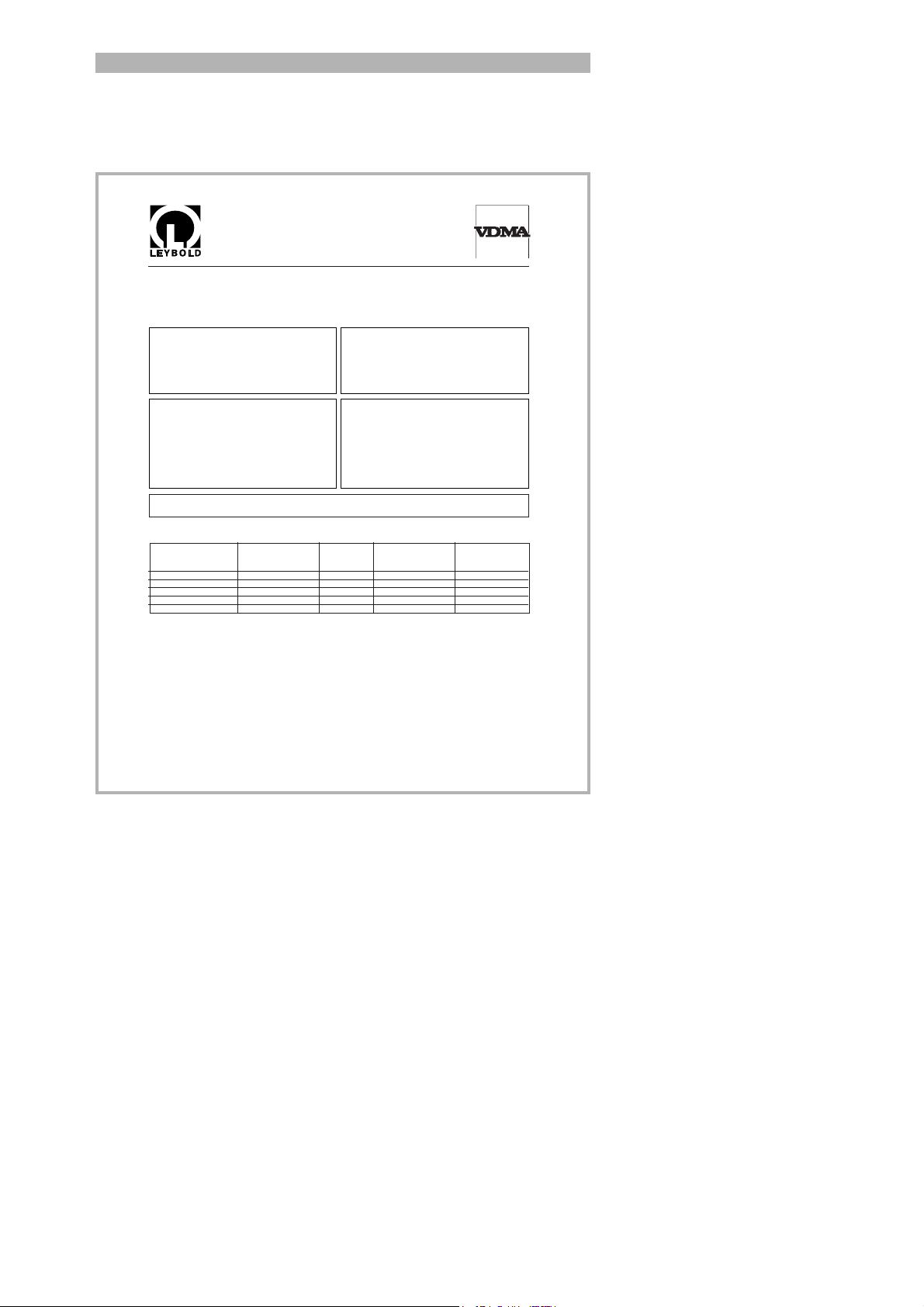
1.2 Support from LEYBOLD Ser-
S A M P L E
Declaration of Contamination of Vacuum Equipment and Components
The repair and/or service of vacuum equipment and components will only be carried out if a correctly completed declaration has
been submitted. Non-completion will result in delay. The manufacturer could refuse to accept any equipment without a declaration.
This declaration can only be completed and signed by authorized and qualified staff.
1. Description of Vacuum Equipment and Components
- Equipment type/model: _________________________________
- Code No.: _________________________________
- Serial No.: _________________________________
- Invoice No.: _________________________________
- Delivery date:
__________________________
2. Reason for Return
____________________________________________
____________________________________________
____________________________________________
____________________________________________
____________________________________________
____________________________________________
3. Condition of the Vacuum Equipment and Components
- Has the equipment been used?
yes ❒ no ❒
- What type of pump oil/liquid was used? _________
- Is the equipment free from potentially
harmful substances?
yes ❒ (go to Section 5)
no ❒ (go to Section 4)
4. Process related Contamination of Vacuum
Equipment and Components:
- toxic yes ❒ no ❒
- corrosive yes ❒ no ❒
- explosive*) yes ❒ no ❒
- biological hazard*) yes ❒ no ❒
- radioactive*) yes ❒ no ❒
- other harmful substances yes ❒ no ❒
*) Vacuum equipment and components which have been contaminated by biological explosive or radioactive substances,
will not accepted without written evidence of decontamination!
Please list all substances, gases and by-products which may have come into contact with the equipment:
Trade name
Product name Chemical name Dangerous Measures First aid in case of
Manufacturer (or Symbol) material class if spillage human contact
1.
2.
3.
4.
5.
5. Legally Binding Declaration
I hereby declare that the information supplied on this form is complete and accurate. The despatch of the contaminated
vacuum equipment and components will be in accordance with the appropriate regulations covering Packaging, Transportation and Labelling of Dangerous Substances.
Name of organisation or company:_____________________________________________________________________
Address: _____________________________ Post code:______________________________________
Tel.: ______________________________________________________________________________
Fax: _____________________________ Telex: _________________________________________
Name: ______________________________________________________________________________
Job title: ______________________________________________________________________________
Date: _____________________________ Company stamp:
Legally binding signature:____________________________________________________________________________
vice
General Information
Fig. 1 Declaration of contamination from
If equipment is returned to LEYBOLD, indicate whether the equipment is
free of substances damaging to health or whether it is contaminated. If it is
contaminated also indicate the nature of the hazard. For this you must use
a form which has been prepared by us which we will provide upon request
or you can take from the technical documentation folder.
Please attach this form to the equipment or enclose it with the equipment.
This declaration of contamination is required to comply with legal requirements and to protect our personal. LEYBOLD must return any equipment
without a declaration of contamination to the sender’s adress.
Before shipping fit the yellow crew-on seals on to the connections
EXHAUST Fig 2/2 and GAS BALLAST Fig 2/3.
GA10.218_1.01 - 11/2004
⏐ 9

General Information
1.3 Introduction
1.3.1 Purpose
The PhoeniX is a helium leak detector. This instrument may be used to
detect the location and the size of leaks on objects under test in two different ways:
• when the test sample has been evacuated first and is sprayed with
helium on the outside. It is required that a vacuum connection is provided between the PhoeniX and the test sample (vacuum mode).
or
• when a helium overpressure is provided in the test sample and the test
sample is searched from the outside with a sniffer probe which is attached to the inlet port (sniffer mode).
Caution The PhoeniX is to be used for leak detection only. It must not be
used as a pumping system (esp. pumping aggressive or humid
gases.)
Pumping condensable gases and steams: When pumping test sample
water vapour that is inside the test object can attain to the fore pump.
With the water vapor that is in the air - especially in humid areas or when
using humid or wet test samples - the acceptable compatibility of water
vapor or capacity of water vapor respectively can be exceeded.
The steam in the oil of the pump condeses when the water vapor rises
over the acceptable value. So the attribute of the oil changes and danger
of corrosion occures for the pump.
While using the leak detector with condensable gases and steams the oil
of the fore pump has to be controlled regularly. So you can recognize a
condensation of water vapor in the pump. Usually the oil is light and
lucent. When water vapor is inside it gets blear and milky at operating
state temperature.
When turning the pump off water vapor condensates and raises the part
of water in the oil.
Caution The leak detector must not directly be switched off after the pro-
cess, in which condensable gases or steams are pumped, is
finished. It must be running (at least 20 minutes) with opend gas
ballast valve (see Chapter 5.3.1) until the oil of the pump is freed
from detached steams.
When not taking care of this instruction there can be a corrosion
within the pump, which will not be covered by our warranty.
The heighth of the oil of the pump has to be controlled regularly.
The normal intervalls of changing the oil from the producer have
to be taken care of. See instructions of the rotary vane pump.
If the PhoeniX will be used in an application with toxic materials please
contact Leybold for appropriate decontamination rules. Should the unit
will be in contact with dangerous gases, the declaration of contamination
has to be filled in.
10
⏐
GA10.218_1.01 - 11/2004

1.3.2 Technical Data
1.3.2.1 Physical Data PhoeniXL300
Max. inlet pressure 15 mbar
Minimum detectable Helium leak rates
• in vacuum mode ≤5×10
• in sniffer mode <1×10
Maximum Helium leak rate which can be displayed 0.1 mbar l/s
Measurement range 12 decades
Time constant of the leak rate signal (blanked off,
63% of the final value)
Pumping speed (Helium) at the inlet
– GROSS mode 0.4 l/s
– FINE mode > 2.5 l/s
Detectable masses 2, 3 and 4
Mass spectrometer 180°
Ion source 2 filaments;
Inlet port DN 25 KF
Run-up time (after starting) ≤ 2min
-12
mbar l/s
-7
mbar l/s
<1 s
magnetic sector field
Iridium/Yttria-oxide
General Information
To get down to the minimum detected leak rate range some conditions
must be fulfilled:
• PhoeniX has fully warmed up
• Ambient conditions must be stable (temperature, no vibration/accelerations.)
• The part under test has been evacuated long enough (background is no
longer decreasing)
• ZERO must be active
1.3.2.2 Electrical Data
Power supply 230 V, +/- 5%, 50 HZ
115 V, +/- 5%, 60 Hz
Power consumption 420 VA
Type of protection IP40
Power cords (EU, USA, UK) 2.5 m
GA10.218_1.01 - 11/2004
⏐ 11

General Information
1.3.2.3 Other Data
Valves solenoid
Dimensions (L × W × H) in mm 490 x 430 x 315
Weight in kg 40.0
Noise level dB (A) < 54
Audio alarm dB (A) 95
Contamination level (to IEC 60664-1) 2
Overvoltage category (to IEC 60664-1) II
1.3.2.4 Ambient Conditions
For use within buildings
Permissible ambient temperature (during operation) +10 °C … +40 °C
Permissible storage temperature 0 °C … +60 °C
Max. rel. humidity 80% (up to 31°C)
linear decreasing to
50% at 40°C
Max. permissible height above sea level
2000 m
(during operation)
1.3.2.5 Physical Data PhoeniXL300 dry
Max. inlet pressure 15 mbar
Minimum detectable Helium leak rates
• in vacuum mode ≤2×10
• in sniffer mode <1×10
-11
mbar l/s
-7
mbar l/s
Maximum Helium leak rate which can be displayed 0.1 mbar l/s
Measurement range 12 decades
Time constant of the leak rate signal (blanked off,
<1 s
63% of the final value)
Pumping speed (Helium) at the inlet
– GROSS mode 0.02 l/s
– PRECISION mode 0,4 l/s
– FINE mode > 2.5 l/s
Detectable masses 2, 3 and 4
Mass spectrometer 180°
magnetic sector field
Ion source 2 filaments;
Iridium/Yttria-oxide
Inlet port DN 25 KF
Run-up time (after starting) ≤ 2min
12
⏐
GA10.218_1.01 - 11/2004

1.3.2.6 Electrical Data
Power supply 230 V, 50 HZ
115 V, 60 Hz
Power consumption 350 VA
Type of protection IP40
Power cords (EU, USA, UK) 2.5 m
1.3.2.7 Other Data
Valves solenoid
Dimensions (L × W × H) in mm 490 x 430 x 315
Weight in kg 35.5
Noise level dB (A) < 54
Audio alarm dB (A) 95
Contamination level (to IEC 60664-1) 2
Overvoltage category (to IEC 60664-1) II
General Information
1.3.2.8 Ambient Conditions
For use within buildings
Permissible ambient temperature (during operation) +10 °C … +40 °C
Permissible storage temperature 0 °C … +60 °C
Max. rel. humidity 80% (up to 31°C)
linear decreasing to
50% at 40°C
Max. permissible height above sea level
(during operation)
2000 m
GA10.218_1.01 - 11/2004
⏐ 13

General Information
1.3.2.9 Physical Data PhoeniXL300 Modul
Max. inlet pressure 15 mbar
Minimum detectable Helium leak rates
• in vacuum mode
-12
– with Scroll pump ≤8×10
– with oil sealed pump ≤5×10
• in sniffer mode <1×10
mbar l/s
-12
mbar l/s
-7
mbar l/s
Maximum Helium leak rate which can be displayed 0.1 mbar l/s
Measurement range 12 decades
Time constant of the leak rate signal (blanked off,
<1 s
63% of the final value)
Pumping speed (Helium) at the inlet
– GROSS mode 1,0 l/s
– FINE mode > 2.5 l/s
Detectable masses 2, 3 and 4
Mass spectrometer 180°
magnetic sector field
Ion source 2 filaments;
Iridium/Yttria-oxide
Inlet port DN 25 KF
Run-up time (after starting) ≤ 2min
1.3.2.10 Electrical Data
Power supply 100V ...230 V,
50/60 HZ
Power consumption 350 VA
Type of protection IP40
Power cords (EU, USA, UK) 2.5 m
1.3.2.11 Other Data
Valves solenoid
Dimensions (L × W × H) in mm 490 x 430 x 315
Weight in kg 29.5
Noise level dB (A) < 54
Audio alarm dB (A) 95
Contamination level (to IEC 60664-1) 2
Overvoltage category (to IEC 60664-1) II
14
⏐
GA10.218_1.01 - 11/2004

1.3.2.12 Ambient Conditions
For use within buildings
Permissible ambient temperature (during operation)+10 °C … +40 °C
Permissible storage temperature 0 °C … +60 °C
Max. rel. humidity 80% (up to 31°C)
linear decreasing to
50% at 40°C
Max. permissible height above sea level
(during operation)
2000 m
General Information
GA10.218_1.01 - 11/2004
⏐ 15

General Information
1.4 Unpacking
Unpack the PhoeniX immediately after delivery, even if it will be installed
later on.
Examine the shipping container for any external damage. Completely
remove the packaging materials.
Check the PhoeniX is complete (See Chapter 1.4.1 Supplied Equipment)
and carefully examine the PhoeniX visually.
If any damage is discovered, report it immediately to the forwarding agent
and insurer. If the damaged part has to be replaced, please contact the
orders department.
Retain the packaging materials in the event of complaints about damage.
For unpacking please use the wedge which is part of the packaging.
1.4.1 Supplied Equipment
• Helium Leak Detector PhoeniX
• Set of fuses
• Power cord
• Folder with documents
• Technical Handbook PhoeniX
• Spare Parts List PhoeniX
• 2 L-type screwed connections (hose connections)
• 1 hose nozzle
• Blank flange DN 25 KF
• Clamping ring DN 25 KF
• Centering ring DN 25 KF
1.4.2 Accessories and Options
The following parts can be ordered additionally:
• Sniffer Line SL300 252003
• Leak Ware 14090
• Helium Sniffer QUICK-TEST QT100 15594
• Remote Hand Set
– Hand Set
20099022L
16
⏐
GA10.218_1.01 - 11/2004
– Cable (required), 4 m
– Extension Cable, 8 m
• Spray gun with hose 16555
• Set of connection plugs 20028782
1.4.2.1 Sniffer line SL300
By use of the sniffer line the PhoeniX can easily be converted to a sniffer
leak detector. The length of the sniffer line is 4m (i.e. 12 feet).
20099027
14022

Installation: The sniffer line is to be adapted to the KF 25 of the Phoenix
with the small flange. Then the plug of the sniffer line is to be connected to
the input „Options“ of the Phoenix.
General Information
Function:
- the Phoenix is ready for use and
- the selected trigger level is not exceeded
The red LED is on when
- the Phoenix is not ready for use or
- the selected trigger level is exceeded.
The pushbutton in the grip is for the zero function. When pushing the button the helium background will be suppressed. For cancelling the zero
function push the button once more.
Options for the sniffer line:
• Sniffer tip rigid 120 mm 12213
• Sniffer tip rigid 385 mm 12215
• Sniffer tip flexible 120 mm 12214
• Sniffer tip flexible 385 mm 12216
• Capillary filter metal ( for rough conditions) 12217
Spare parts for the sniffer line
• Capillary filter plastic (5 pcs) 20003501
• Sinter filter with seal (5 pcs) 20003500
• Felt disc for capillary filter (50 pcs) 200001116
The green LED is on when
1.4.2.2 Hand set
The hand set is a remote control to operate the PhoeniX from distance up
to 30 m. It provides the fuctions START, STOP/VENT, ZERO and speaker
volume, and displays leak rate in bargaraph.
The remote control is provided with a magnet. So it can be attached to
metallic surfaces.
GA10.218_1.01 - 11/2004
⏐ 17

General Information
18
⏐
GA10.218_1.01 - 11/2004

2 Installation
2.1 Working Location
when exposed to drip water. The same applies to all other kinds
of liquids.
to extreme climatic conditions.
discharge openings must never be obstructed.
Installation
CautionThe PhoeniX must not be operated while standing in water or
AttentionAvoid contact with bases, acids or solvents as well as exposure
AttentionThe PhoeniX is designed for indoor use only.
AttentionEnsure a sufficient air cooling. The air inlet as well the air
It is recommended that you check all major helium sources in the vicinity
of the PhoeniX within a radius of about 10 m for the presence of any big
leaks. You may use the sniffer probe for this.
2.2 Electrical Connections
2.2.1 Mains Power
Generally the local regulations for electrical connections must be observed.
that the mains voltage rating of the PhoeniX coincides with the
locally available mains voltage. The instrument must exclusively
be connected to a single phase supply with fuses for installation
(Circuit breaker 10A max. according to IEC/EN 60898 with tripping characteristic B).
must be used. Operation of the PhoeniX where the ground conductor has been left unconnected is not permissible.
CautionBefore connecting the PhoeniX to the mains you must make sure
AttentionOnly 3-core mains cables having a protection ground conductor
The mains voltage rating for the PhoeniX can be read off from the name
plate beneath the mains socket Fig. 2/4 at the side. This voltage is fixed
and can not be changed.
A separate fuse for each of the mains conductors has been integrated into
the mains switch.
The mains voltage is applied to the instrument via the detachable mains
cable which is supplied with the instrument. A mains socket Fig. 2/4 is
available for this purpose at the side of the instrument.
GA10.218_1.01 - 11/2004
⏐ 19
Installation
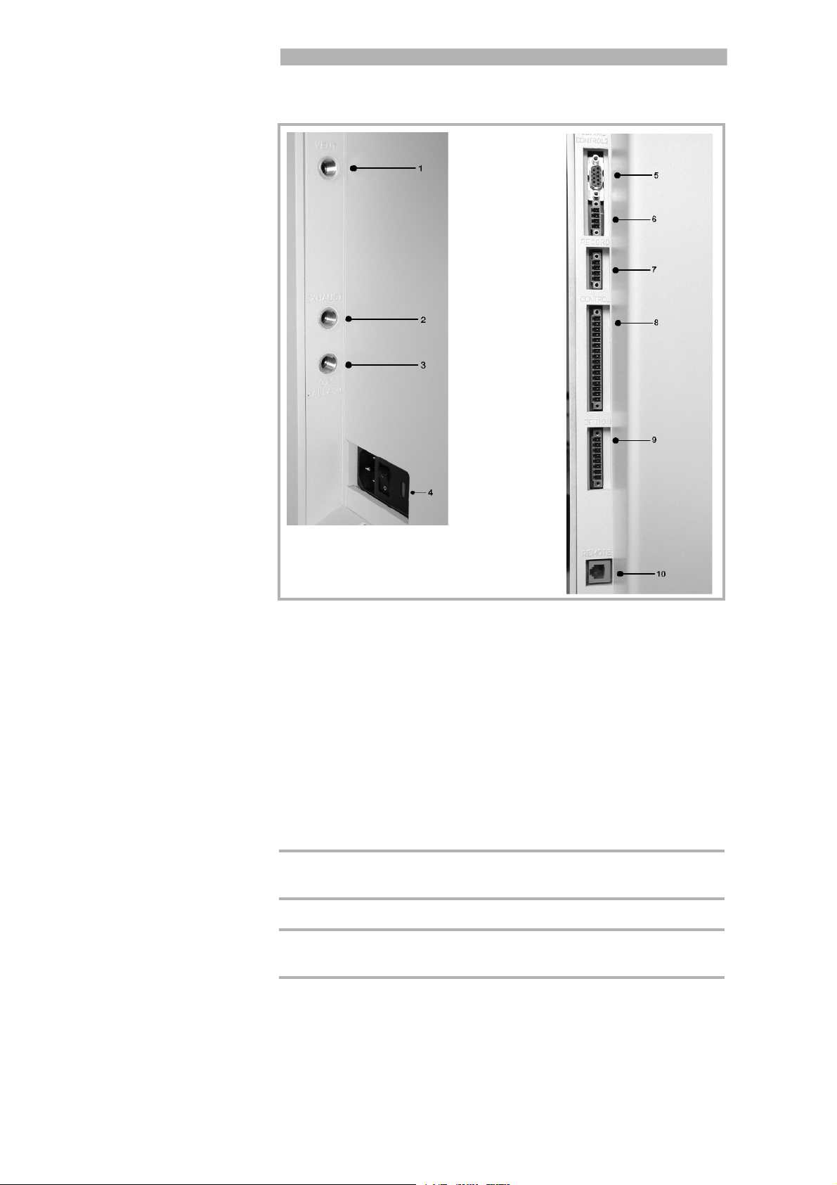
1. Vent
2. Exhaust
3. Gasballast
4. On / Off
5. Serial
6. Control 2
7. Record
8. Control
9. Option
10. Remote
Fig. 2
2.2.2 Connections for the Data Acquisition
Systems
2.2.2.1 Option (Accessories)
The sniffer line SL300 or the partial flow system may be connected to the
option port (Please refer to Chapter Fig. 2/9):
Contact pins 1 and 3 are fused together with a 0.8 A slow-blow fuse. The
amount of power which can be drawn is limited to 10 W. The contacts are
numbered from bottom to top.
Pin
1 +24 V, constantly applied, power supply for the LEY-
2GND
3, +24V switched by the PhoeniX for an external venting
4, 5, 6, 7, 8 These pins are used in connection with accessories.
Assignment
BOLD partial flow valve or sniffer line.
valve
20
⏐
GA10.218_1.01 - 11/2004

2.2.2.2 Digital Out
The following relay outputs are available for further signal processing. The
maximum rating for the relay contacts is 60V AC/1A.
The contacts are numbered from bottom to top.
Pin Assignment
1 PLC in free selectable
2 PLC in free selectable
3 PLC in free selectable
4GND
5 to 7 Digital out free selectable, 5 center contact, 6 normally open
contact, 7 normally closed contact
8 to 10 Digital out free selectable
11 to 13 Digital out free selectable
Installation
14 to 16 Digital out free selectable
Description of the operation mode of the Digital Out. The pin assignement
for contacts 8 to 16 follows the same order as for pins 5 to 7.
The following digital out signals are selectable.
Trigger 1:
Is open in case Trigger Level 1 is exceeded or the machine is not in condition of measuring.
Trigger 2:
Is open in case Trigger Level 1 is exceeded or the machine is not in condition of measuring.
Trigger 3:
As Trigger 1 and Trigger 2
Zero active:
Is closed in case Zero function is running.
Ready:
Is closed in case machine is ready for measurement (Emission on, no
error).
CAL active
Closed when machine is in calibrating routine.
CAL Request
Is opend in case of calibration request. During external calibration a open
output indicates that the external calibrated leak has to be closed.
Fail
Open when a error is shown.
Warning
Open when a warning is shown.
Gas ballast
Closed when gas ballast is active.
GA10.218_1.01 - 11/2004
⏐ 21

Installation
Open
Always open.
Close
Always close
Recorder Strobe
Closed in case recorder output is invalid. Only used when record output is
set on „leak rate“.
2.2.2.3 Digital In
These inputs can be used to control the PhoeniX with a programmable
logic control (PLC).
Pin Assignment
1 PLC in free selectable
2 PLC in free selectable
3 PLC in free selectable
4PLC GND
Description of operation mode of the Digital In.
Zero:
Change from low to high: activate zero
Change from high to low: deactivate zero
Start:
Change from low to high: activate START
Stop:
Change from low to high: activate STOP
When this inlet is longer high than anounced then ventilate it additionaly.
Gas Ballast:
Change from low to high: activate purge
Change from high to low: deactivate purge
Clear:
Change from low to high: confirm error message
CAL:
Change from low to high:
When machine is in stand-by mode: start internal calibration. In case
machine is measurement mode: start external calibration. (Premise: external calibration test leak has to be open and leak rate signal is stable)
Change from high to low:
External calibration: approve that external test leak is closed and leak rate
signal is stable.
High means: U > 13V(approximately 7mA)
Low means: U < 7V
The level of the logic signals must not exceed 35V.
22
⏐
GA10.218_1.01 - 11/2004
CAL intern:
The Machine starts an internal calibration independent from the mode the
machine is running in.

CAL extern:
The Machine starts an external calibration independent from the mode the
machine is running in.
Signals at these inputs are only accepted if the location of control is set to
„PLC“ or „Local and PLC“. Refer to Chapter 6.6.4.1
2.2.2.4 Recorder
The recorder output Fig. 2/7 may be used to chart the leak rate, the inlet
pressure and the forevacuum pressure. Both recorder activities can be
adjusted individually for showing leak rates and pressures.
The measured values are provided by way of an analogue signal in the
range of 0 V … 10 V. The resolution is limited to 10 mV. The instrument
which is connected to the recorder output (e. g. X(t) chart recorder) should
have an input resistance of no less than 2.5 kΩ. The measured values are
available through pins 1 and 4. The reference potential (GND) is available
at pins 2 and 3. The contacts are numbered from bottom to top.
The chart recorder outputs are electrically isolated from other plugs. If, in
spite of this, hum interference is apparent it is recommended to operate
the PhoeniX and the chart recorder from the same mains phase. If this is
not possible, you must make sure that the frame ground of both instruments is kept at the same potential.
Installation
Pin Assignment
1 Analog 1, leak rate, inlet pressure P1 or forevacuum pressure P2
2GND
3GND
4 Analog 2, leak rate, inlet pressure P1 or forevacuum pressure P2
GA10.218_1.01 - 11/2004
⏐ 23

Installation
2.2.2.5 RS232
This RS232 interface Fig. 2/5 is wired as data communication equipment
(DCE) and permits the connection of a personal computer (PC) for monitoring and data logging. The connection is made through a 9 pin sub-D
socket. For more information refer to the Interface Description.
Pin Assignment
1 24 V switchable, default setting 0
2TXD
3RXD
4GND 24V
5GND
6DSR
7CTS
8RTS
9free
2.2.2.6 Hand Set
This hand set interface Fig. 2/10 is a serial interface to control the PhoeniX
by the hand set. The hand set can be connected via an extension cable
with a RJ45 plug. Refer to the Interface Description for more information.
The hand set does not belong to the standard equipment.
Pin
2 +24V (fuse 0.8 A time lag)
30V
4 RXD (intern. RS232)
5 TXD (intern. RS232)
Assignment
2.3 Vaccum Connections
2.3.1 Inlet Port
The inlet port is located on the top of the PhoeniX. The size of the flange is
DN 25 KF.
24
⏐
GA10.218_1.01 - 11/2004
A test object or a test chamber has to be connected to the inlet port if the
vacuum mode is chosen (See Chapter 6.3).
The inlet port is also used for the connection of the sniffer line.

2.3.2 Exhaust
The exhaust Fig. 2/2 flange is located on the side of the PhoeniX.
There is a filter mounted in the exhaust that absorbs the oil steams occuring during the use of the rotary vane pump. The exhaust filter has to be
cleaned when doing the maintenance.
be put out-of-doors using the provided adapter. So the oil
steams that are harmful to health are lead off.
With the provided connection a hose line can be connected to the exhaust
of the PhoeniX and lead off.
2.3.3 Vent
Usually the parts under test are vented with ambient air when the test is
finished. If it is required the parts can be vented with a different gas (i. e.
fresh air, dry air, nitrogen, …) at atmospheric pressure. In this case a vent
hose has to be connected to the hose coupling Fig. 2/1.
Installation
CautionWhen the Phoenix is running in closed rooms the exhaust has to
2.3.4 Gas ballast connection
For the mode gas ballast it is recommended to use helium-free gases at
atmospheric pressure. Ambient air can be contaminated with helium due
to
spraying or charging. In this case a gas supply line (i. e. nitrogen, fresh
air, …) should be connected to the hose coupling Fig. 2/3. The pressure of
these gas line must not exceed 1050 mbar.
The connector 1,2 and 3 in Fig. 2 are quick connectors for hose diameters
of 8/6 mm.
GA10.218_1.01 - 11/2004
⏐ 25

Installation
2.4 Default settings
The following parameters are set like shown when in the menu of the
PhoeniX under Settings → Parameters, Load → Save is chosen.
Scale logarithmic
Display range: 4 decades
Time axis: 32 seconds
LCD inverted off
Background in stand by mode: off
Calibration request: off
Mass: 4 (helium)
Recorder: leak rate
Volume: 2
Leak rate unit: mbar l/s
Mode: Vacuum
Trigger level 1: 1E-9 mbar l/s
Trigger level 2: 1E-8 mbar l/s
Trigger level 3: 1E-7 mbar l/s
Leak rate external test leak (vacuum): 1E-7 mbar l/s
Leak rate external test leak (sniffer): 1E-5 mbar l/s
Vent delay: 2 seconds
Automatic purge (PhoeniXL300 and Modul only) on
Pressure: mbar
Minimum volume: 0
Beep: on
Maximum evacuation time: 30 minutes
Audio Alarm Type: Trigger Alarm
Max. pressure limit for sniff mode 0.15 mbar
Min. pressure limit for sniff mode 0.05 mbar
Control location local
Alarm delay: 30 seconds
Leak rate filter: auto
Zero: enable
Vacuum ranges normal
Upper display limit 1E-5 mbar l/s
Service message oil filter (PhoeniXL
300
only)
on
26
⏐
GA10.218_1.01 - 11/2004

3 First Operation
Check
The steps for an initial operation are described in this chapter. It is explained how to switch on the PhoeniX, how to measure and how to carry out
an internal calibration.
If anything unexpected happens during the initial operation or the leak
detector acts in a strange way the PhoeniX can be switched off by the
mains switch at any time.
3.1 Needed Equipment
The following parts will be needed:
• A blind flange 25 KF (if not preassembled at the inlet port).
• A helium test leak with a DN 25 KF adapter (optional).
• A forevacuum pump (dry or wet version) for use with the PhoeniXL300
Module
First Check
3.2 Description of the Initial Ope-
ration
Please proceed the following description step by step to start the initial
operation. Refer to Chapter 5 for a more detailed description.
3.2.1 Startup and Measure
1. Unpack the PhoeniX and inspect it for any external damage (Refer to
Chapter 1.4).
2. Connect the instrument to the mains power (Refer to Chapter 2.2.1).
For the PhoeniXL300 Modul connect the forevacuum pump and switch
it on.
3. Switch on the leak detector by using the mains switch Fig. 2/4.
GA10.218_1.01 - 11/2004
⏐ 27
Operation Check
Fig. 3 View PhoeniX
Caution Don’t switch the PhoeniX on when ambient temperature is
below 10°C.
After power on a welcoming picture appears on the screen of the control
panel Fig. 4/1, the status information on the speed of the turbo pump, the
foreline pressure, the emission and the active filament are given.
The start up procedure takes about 2 minutes and the end is indicated by
a beep. The PhoeniX is in Stand-by mode now.
4. Check if the inlet port is blanked off. If not, please mount a blind flange
with o-ring on the inlet port.
5. Press the START Button Fig. 4/10. The inlet will be evacuated and the
measured leak rate will be displayed a moment later.
This is the measurement mode. If a test part was connected you would
start spraying Helium to identify leaks.
2
1
3
4
6
7
8
10
11
28
⏐
GA10.218_1.01 - 11/2004
5
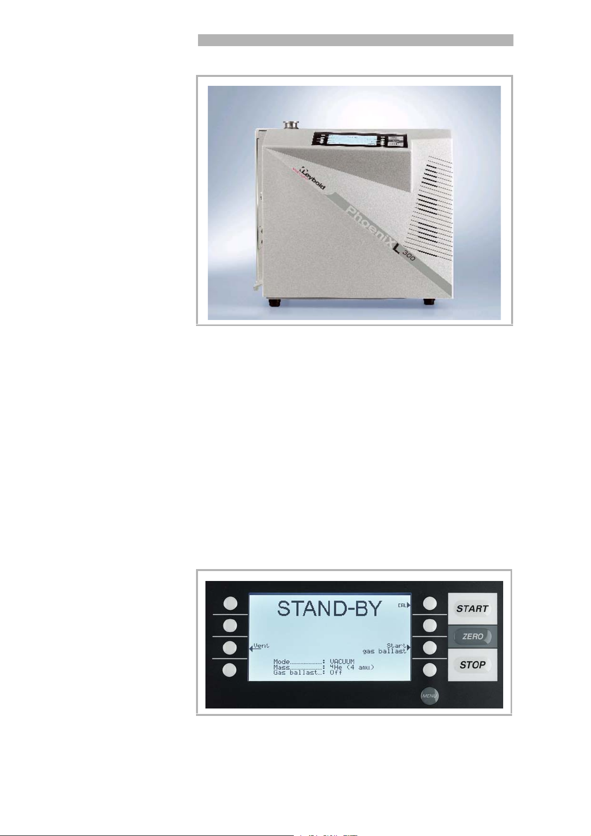
Fig. 4 Control panel
9
13
12

Pos. Description Pos. Description
1 LC Display 8Soft Key no. 7
2 Soft Key no. 1 9 Soft Key no. 8
3 Soft Key no. 2 10 START Button
4 Soft Key no. 3 11 ZERO Button
5 Soft Key no. 4 12 STOP Button
6 Soft Key no. 5 13 MENU Button
7Soft Key no. 6
6. To correct for any background signal (residual Helium in the part under
test) you may press the ZERO Button Fig. 4/11. To undo ZERO please
press the ZERO Button for 2 … 3 seconds.
7. Press the STOP Button Fig. 4/12, the Phoenix will go to Stand-by. If you
press STOP a few seconds the inlet of the Phoenix will be vented.
8. To finish the startup procedure please proceed with #16.. For calibration proceed with #9.
3.2.2 Internal Calibration
First Check
9. Proceed the internal calibration (Please refer to Chapter 7.2.1). For better quantitative measurements please allow the unit to warm up
(15 … 20 minutes).
• Press Calibration (Soft Key no. 5 Fig. 4/6) to get into the calibration
menu.
• Select internal (Soft Key no. 4) to choose the internal calibration.
• The internal calibration starts automatically and takes about 30 sec-
onds.
10. Press the STOP Button Fig. 4/12 until the message STAND-BY /
VENTED appears on the display. The inlet is vented now.
3.2.3 Verification
To verify the accuracy please proceed through the following steps. A test
leak is required. If a test leak is not available please continue with #16..
11. Remove the blind flange from the inlet port and connect the open
helium test leak to the inlet port.
12. Press the START Button Fig. 4/10 again. The inlet will be evacuated
and the leak rate of the test leak will be measured and displayed.
13. Press the STOP Button Fig. 4/12 to interrupt the measurement. The
Stand-by mode will be displayed.
14. Press the STOP Button Fig. 4/12 again until the message STAND-BY
vented appears an the display. The inlet is vented now.
15. Remove the helium test leak from the inlet port and put a blind flange
onto the inlet port again.
16. Switch off the leakdetector by using the mains switch Fig. 2/4.
The first operation is finished.
GA10.218_1.01 - 11/2004
⏐ 29

Operation Check
30
⏐
GA10.218_1.01 - 11/2004
 Loading...