

Leybold vacuum TURBO.DRIVE 400, 800073V0002, 800073V0003, 800073V0004, 800073V0008 Operating Instructions Manual
TURBO.DRIVE 400
Frequency Converter for
Turbomolecular Pumps
Operating Instructions 17200492_002_A5
Part Numbers
800073V0002
800073V0003
800073V0004
800073V0008
D
r
ive (
DC 2
X
3)
4
V(X4)
H
EAT
S
IN
K
H
EAT
S
IN
K

Contents
Page
Important Safety Information 4
1 Description 7
1.1 Design and function 7
1.2 Standard equipment 7
1.3 Technical data 8
1.4 Ordering data 10
1.5 Accessories 10
2 Installation 13
2.1 Conforming utilization 13
2.2 Operating environment 14
2.3 Mounting the frequency converter 15
2.4 Connecting the pump 16
2.5 Connecting the power supply 16
2.6 Relay status 21
3 Operation 22
3.1 Start-up 22
3.2 Interfaces 23
3.2.1 RS 232 C interface (SERVICE X5) 26
3.2.2 RS 485 interface 27
3.2.3 Profibus DP 29
3.2.4 USB interface (X106) 30
3.2.5 Parameter list 31
3.2.6 Specific parameter data for the pumps 36
3.2.7 Warning codes for parameter 227 38
3.3 Switching on 40
3.4 Shutting down 41
3.5 Emergency shut down 41
3.6 Setting pumping speed and rotational speed 42
3.7 Operation at reduced current 43
3.8 Changing the frequency dependent normal
operation level 44
3.9
3.10 Changing the start delay time 46
3.11 Selecting relay functions 47
3.12 Reading the error memory 47
Changing the maximum permissible run up time 45
2
17200492_002_A5 - 04/2011 - © Oerlikon Leybold V
acuum
Contents / Safety Information
4 Maintenance 48
5 Troubleshooting 49
6 Waste Disposal 57
EC Conformance Declaration 59
Obligation to Provide Information
Before installing and commissioning the TURBO.DRIVE,
carefully read these Operating Instructions and follow
the information so as to ensure optimum and safe
working right from the start.
The Oerlikon Leybold Vacuum TURBO.DRIVE 400 has
been designed for safe and efficient operation when used
properly and in accordance with these Operating
Instructions. It is the responsibility of the user to carefully
read and strictly observe all safety precautions described in
this section and throughout the Operating Instructions. The
TURBO.DRIVE
tion and under the conditions described in the Operating
Instructions
personnel only. Consult local, state, and national agencies
regarding specific requirements and regulations. Address
any further safety, operation and/or maintenance questions
to our nearest office.
must only be operated in the proper condi-
. It must be operated and maintained by trained
NOTICE
DANGER indicates an imminently hazardous situation
which, if not avoided, will result in death or serious injury.
WARNING indicates a potentially hazardous situation
which, if not avoided, could result in death or serious injury.
CAUTION indicates a potentially hazar
if not avoided, could result in minor or moderate injury.
DANGER
WARNING
dous situation which,
17200492_002_A5 - 04/2011 - © Oerlikon Leybold V
CAUTION
acuum
3

Safety Information
NOTICE
WARNING
NOTICE is used to notify users of installation, operation,
programming or maintenance information that is important,
but not hazard related.
We reserve the right to alter the design or any data given in
these Operating Instructions.
The illustrations are not binding.
Retain the Operating Instructions for further use.
Important Safety Information
The frequency converter must only be connected to
power supplies which meet the requirements for functional extra low voltage with positive isolation in accordance with IEC 364 (VDE 0100, Part 410, or local regulations) (PELV).
During operation the frequency converter may attain
temperatures up to 75 °C. We recommend that the unit
be installed so that it can not be touched inadvertently.
NOTICE
Inside the unit there is the risk of suffering burns from
hot components.
The pump may be operated only with a suitable frequency converter and suitable connecting cables.
Ensure correct polarity.
Route all cables so as to protect them from damage.
Disconnect and connect the cable connections only
while the pump is turning no longer (green status LED
off) and with the mains power switched off (yellow
power LED off). Otherwise there is the risk of damaging
the TURBO.DRIVE 400.
4
17200492_002_A5 - 04/2011 - © Oerlikon Leybold Vacuum
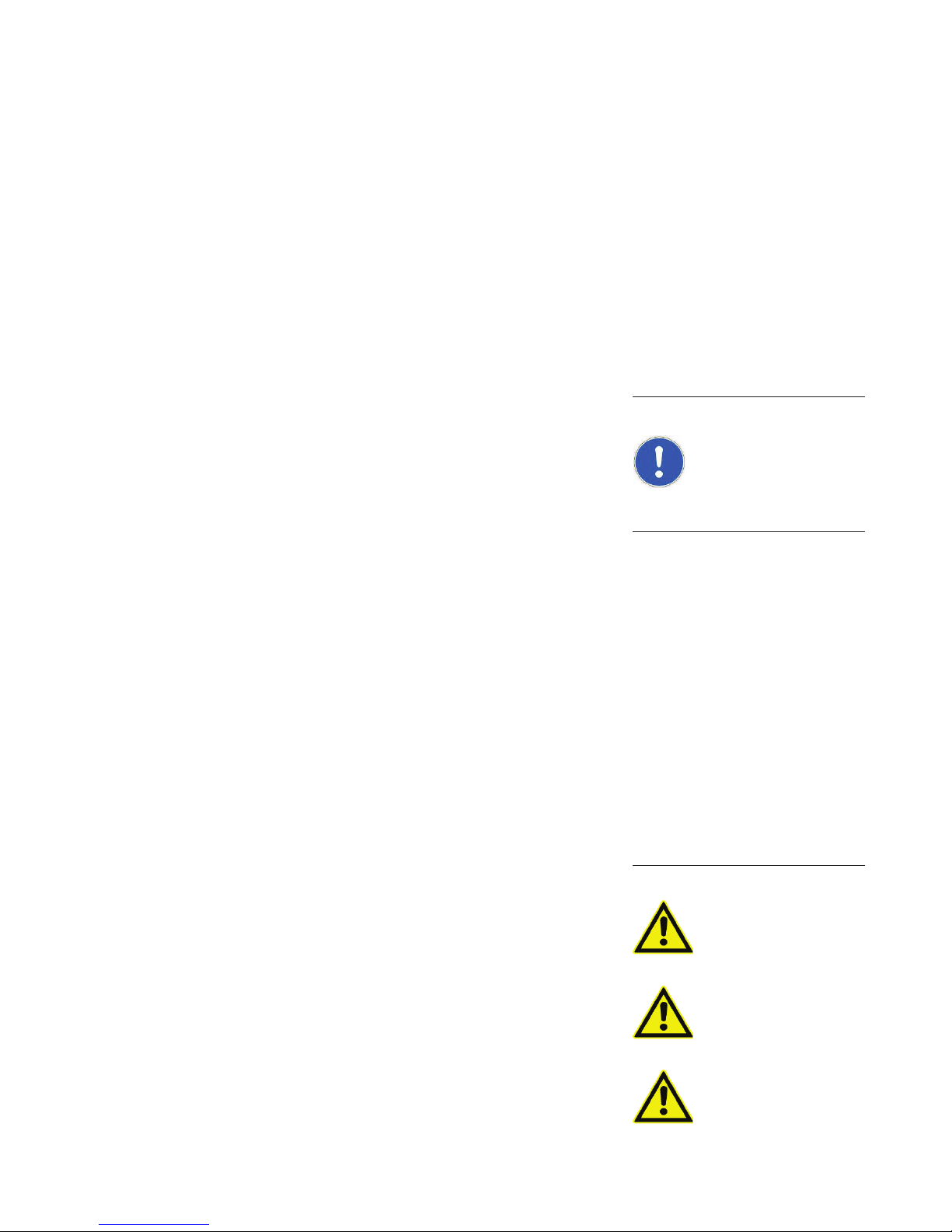
Description
DRIVE (X3)
HEAT SINK HEAT SINK
Pump
connection
connection male 24 V
upply voltage
S
Green LED STS
Yellow LED PWR
24 VDC (X4)
g surfaces
Coolin
off: Pump at standstill (< 3 Hz)
flashes slowly 1/s: Start command is present (about 10 s after start)
flashes fast 3/s: Running up or running down
on: Normal operation
off: No supply voltage
flashes: Supply voltage too low or too high
on: Supply voltage is present
pin Sub-D connector
9
male for RS
fe
TU R B O .DRIVE
TD 400
232 interface
LEDs
REMOTE connector
9 pin Sub-D (female)
Red LED ERR
Fig. 1.1 TURBO.DRIVE 400, front and rear side
off: No error, no warning
flashes: Warning is present, pump can be operated
possibly with some restrictions
on: Fault is present, pump stopped or can not
be operated
17200492_002_A5 - 04/2011 - © Oerlikon Leybold V
acuum
5
Description
connection
9-way Profibus
PRO FIBUS (X105) H IGH LOW
E
E
F
F
D
D
1
C
B
A
9
1
C
2
2
B
3
3
A
4
4
9
5
5
8
8
6
7
6
7
mal format
address in the h
setting the Profibus
Selector switches for
i-
exadec
DRIVE (X3)
HEAT SINK HEAT SINK
24 VDC (X4)
Fig. 1.2 Rear side of TURBO.DRIVE 400 with additional Profibus interface
Selector switch for setting the bus
RS 485 (X104)
TU R B O .DRIVE
TD 400
address for RS 485 communication
in the hexadecimal format
Fig. 1.3 Front side of TURBO.DRIVE 400 with additional RS 485 interface
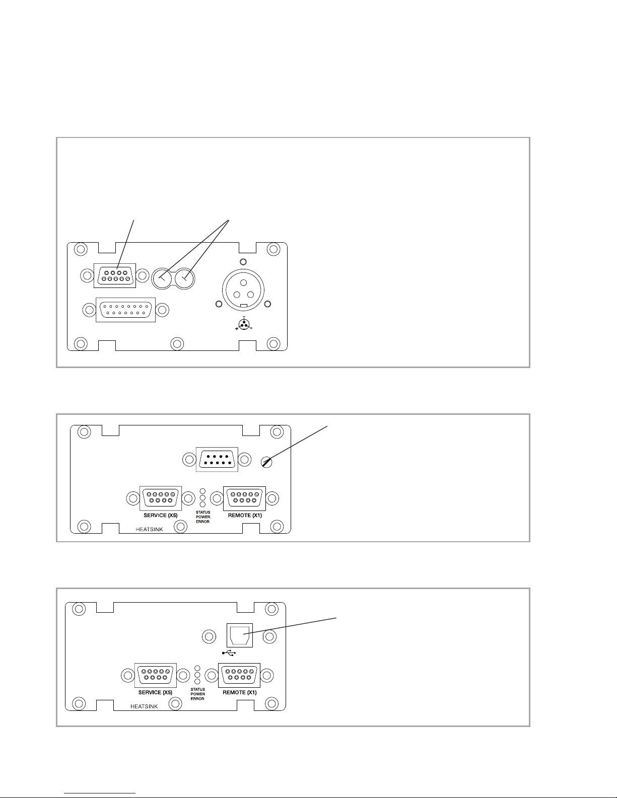
TU R B O .DRIVE
TD 400
Abb. 1.4 FTURBO.DRIVE 400 front panel with additional USB interface
6
17200492_002_A5 - 04/2011 - © Oerlikon Leybold V
USB connection
(X106)
acuum

1 Description
1.1 Design and function
The TURBO.DRIVE 400 supplies power to the TW and SL
series turbomolecular pumps and is used to control their
operation.
The TURBO.DRIVE 400 is either integrated in the pump or
it is separate and linked to the pump by means of a
connecting cable.
The TURBO.DRIVE 400 requires a supply voltage of 24 V
DC. It is equipped with interfaces for programmable controls (REMOTE) and an optional interface for serial communication.
Description
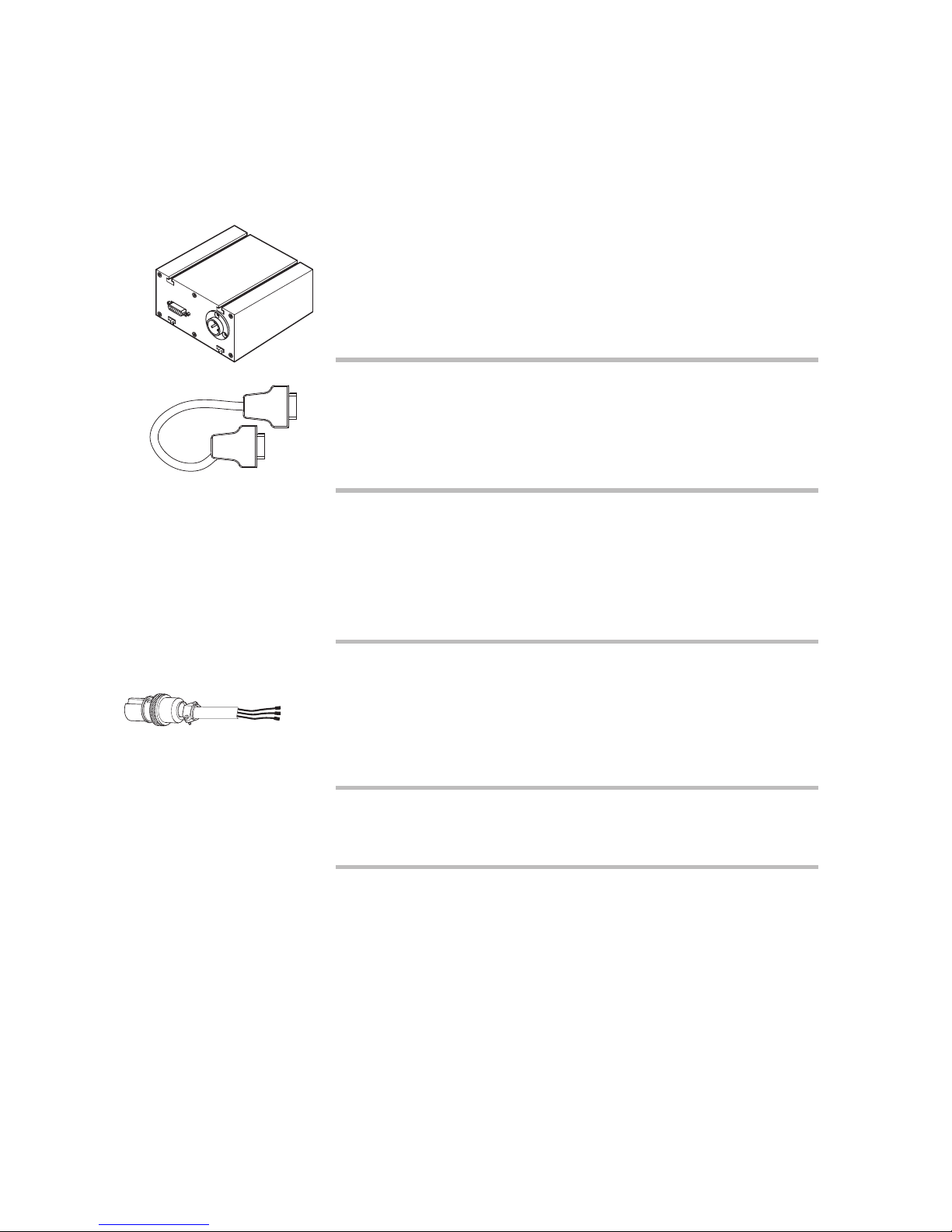
1.2 Standard equipment
Included with the delivery are the DC connector Hirose
HS16P-3, four moving nuts M4 for affixing the frequency
converter and the Operating Instructions.
17200492_002_A5 - 04/2011 - © Oerlikon Leybold V
acuum
7

Description
1.3 Technical data
Supply voltage 24 V (± 10%)
Residual ripple
<3%
Output
Voltage 0 - 24 V 3~
Power 160 W
Frequency 0 - 1500 Hz
When operating a TW 300, TW 300 H, TW 220/150(/15) S,
SL 300
Nominal voltage 24 V
Max. power consumption
190 W
Max. peak current, input side 8 A DC
Required power output from the power supply ≥ 200 W
When operating a TW 70 H, TW 250 S. SL 80
Nominal voltage 24 V
Max. power consumption
140 W
Max. peak current, input side 6 A DC
Required power output from the power supply ≥ 150 W
Max. length of the DC cable (shielded)
at 3 x 1.5 mm
at 3 x 2.5 mm
Relay output rating 42 V, 0.5 A
Ambient temperature
during operation 5 - 45 °C
storage - 15 - + 70 °C
Relative air humidity 5 to 85 %
Overvoltage category II
Contamination grade 2
Temp. of the cooling surface 5 - 55 °C
For Part Nos. 800073V0004 5 - 50 °C
Power consumption ≤ 20 W
2
2
non condensing
5m
20 m
8
17200492_002_A5 - 04/2011 - © Oerlikon Leybold V
Type of protection IP 20
Weight, approx. 0.7 kg
acuum
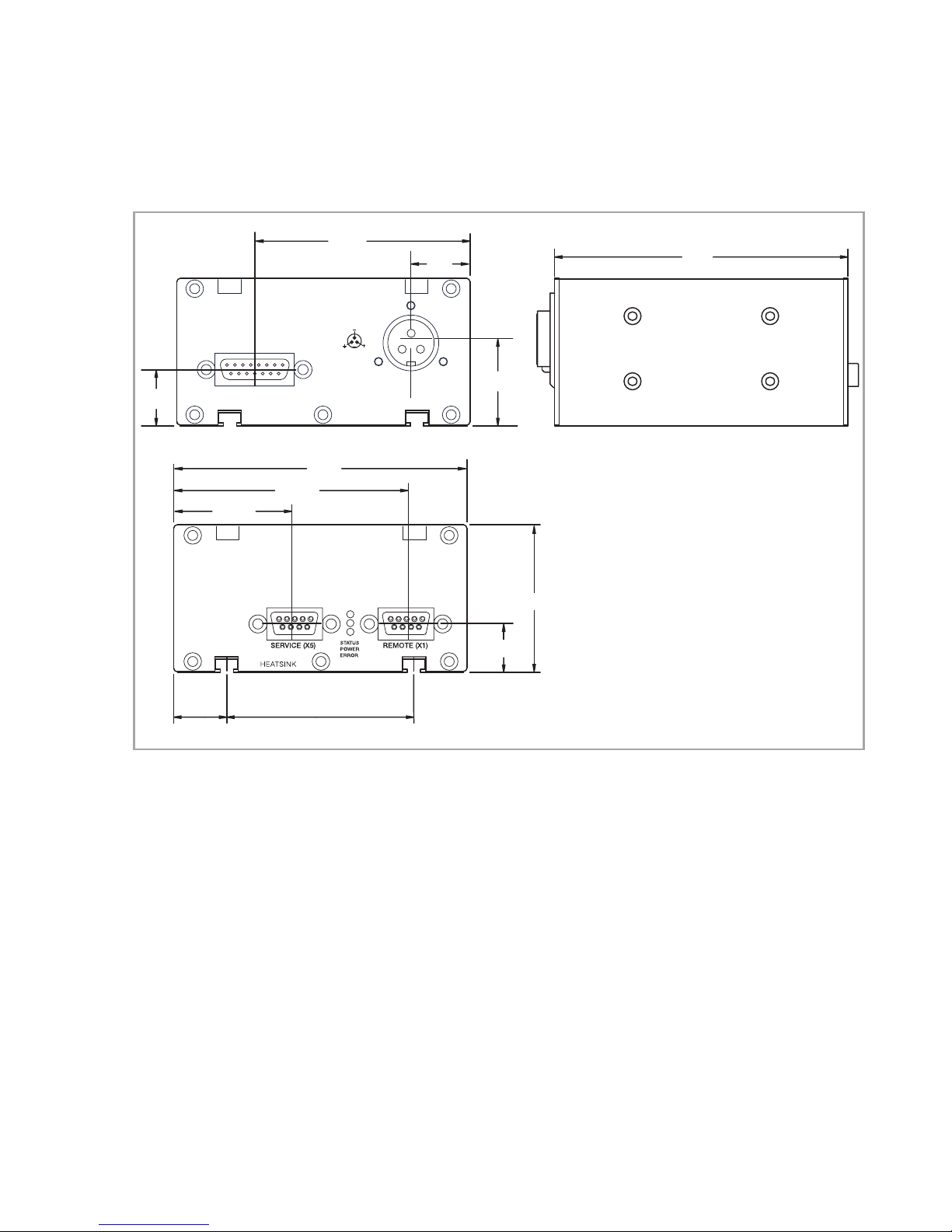
18,5
DRIVE (X3)
HEAT SINK HEAT SINK
79,0
41,0
100
73,3
24 VDC (X4)
32*
27,6
Description
100
* Profibus-Version 20
* Profibus version 20
TURBO.DRIVE
TD 400
50
15,9
18,2 63,8
Fig. 1.5 Dimensional drawing for the frequency converter; dimensions in mm
17200492_002_A5 - 04/2011 - © Oerlikon Leybold V
acuum
9
Description
D
r
i
ve
D
(
X
C24
3)
V
(
X
4)
H
E
A
T
S
I
NK
H
E
A
TS
I
NK
1.4 Ordering data
Frequency converter TURBO.DRIVE 400
with RS 232 C interface 800073V0002
with RS 485 C interface 800073V0003
with Profibus interface 800073V0004
wiht USB interface 800073V0008
Connecting cable pump - frequency converter
1.0 m long 152 47
2.5 m long 864 49
3.0 m long 864 40
5.0 m long 864 50
1.5 Accessories
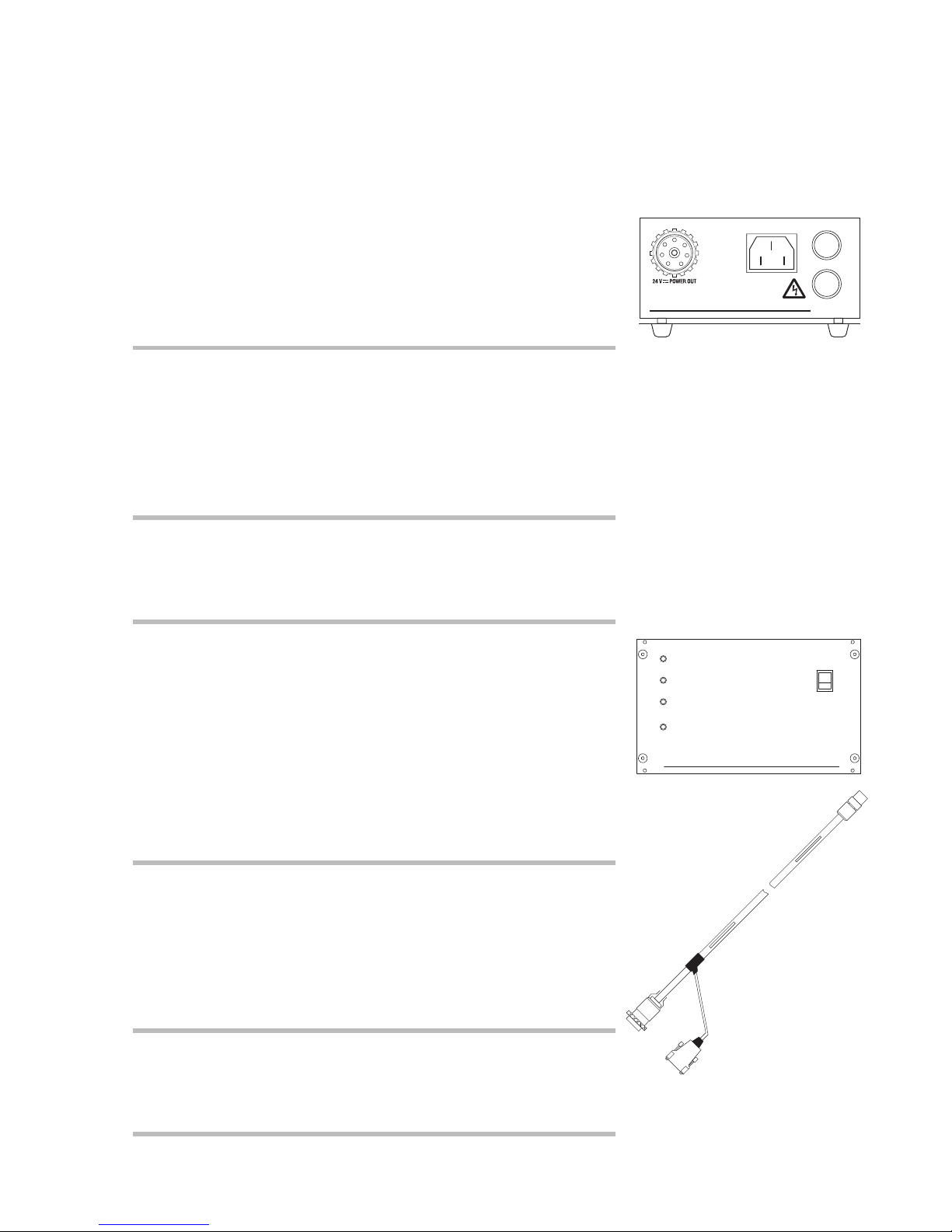
OEM power supply (with screw terminals)
SITOP 24 V / 10 A (120/230 VAC / 50/60 Hz) 152 50
■ supplies the TURBO.DRIVE 400 with 24 V DC
■ other power supplies on request
24 V DC cable
(TURBO.DRIVE 400 – OEM power supply)
3 m 200 12 732
5 m 200 12 733
10 m 200 12 734
20 m 200 12 735
Mains cable for power supply, 2 m long
with EURO plug 800102V0001
with US plug 5-15P 800102V1001
10
17200492_002_A5 - 04/2011 - © Oerlikon Leybold V
acuum
Power supply unit - plug and play
TURBO.POWER 300 800100V0002
■ supplies the TURBO.DRIVE 400 with 24 V DC
■ plug & play cables
■ desktop unit or rack mountable
24V DC Power cable TURBO.DRIVE 400 –
TURBO.POWER 300)
1 m 800094V0100
3 m 800094V0300
5 m 800094V0500
10 m 800094V1000
20 m 800094V2000
Description
100 - 240 V AC
TURBO.POWER 300
T5A~250 V
T5A~250 V
Mains cable for TURBO.POWER 300, 3 m long
with EURO plug 800102V0002
with US plug 6-15P 800102V1002
with UK plug 800102V0003
Power supply and control unit
TURBO.CONTROL 300 800100V0001
■ supplies the TURBO.DRIVE 400 with 24 V DC
■ plug & play cables
■ desktop unit or rack mountable
■ with power switch
■ with start/stop switch for the turbomolecular pump
■ remote control
■ status LEDs and status relays
24V DC Control cable
(TURBO.DRIVE 400 – TURBO.CONTROL 300)
1 m 800091V0100
3 m 800091V0300
5 m 800091V0500
10 m 800091V1000
20 m 800091V2000
START
NORMAL
POWER
ERROR
START
1
0
STOP
TURBO.CONTROL 300
Mains cable for TURBO.CONTROL 300, 3 m long
with EURO plug 800102V0002
with US plug 6-15P 800102V1002
with UK plug 800102V0003
17200492_002_A5 - 04/2011 - © Oerlikon Leybold V
acuum
11
Description
Mechanical accessories
on
off
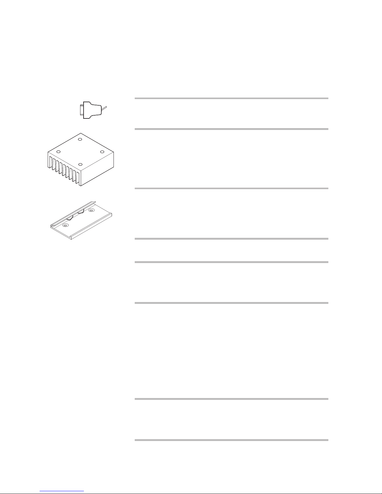
Plug for connector REMOTE with integrated
ON/OFF switch for the pump
(Sub-D plug, 9 way) 152 48
Heat sink for frequency converter 800110V0001
Top hat rail adaptor (mounting aid for
TURBO.DRIVE 400 and TURBO.POWER 300)
800110V0003
Accessories for serial interfaces
USB driver: the Windows driver can be downloaded from
www.oerlikon.com after selecting menu item
www.oerlikon.com in the menu Oerlikon Leybold Vacuum
→ Documentation → Download Software
12
17200492_002_A5 - 04/2011 - © Oerlikon Leybold V
PC software "Turbo.Drive Server" for Windows 95
and higher, CD-ROM
■ Display, change, save and compare parameter lists
■ Integration of customer’s software
■ Record parameter data 800110V0102
(new parameter library for TURBO.DRIVE 400
is required, please ask us for a quotation)
The software can also be downloaded from
www.oerlikon.com in the menu Oerlikon Leybold Vacuum
→ Documentation → Download Software
GSD file for Profibus DP upon request
The software can also be downloaded from
www.oerlikon.com in the menu Oerlikon Leybold Vacuum
→ Documentation → Download Software
acuum

2 Installation
2.1 Conforming utilization
The TURBO.DRIVE 400 supplies power to the TW series
turbomolecular pumps and is used to control their operation.
The TURBO.DRIVE 400 is suited for operation of the following pumps:
■ TURBOVAC TW 70 H
■ TURBOVAC TW 220/150 S, TW 220/150/15 S,
TW 400/300/25 S
■ TURBOVAC TW 250 S
■ TURBOVAC TW 290 H
■ TURBOVAC TW 300, TW 300 H
Installation
■ TURBOVAC SL 80, SL 300
Other pumps may only be operated after approval from
Oerlikon Leybold Vacuum or if the operation of such pumps
is expressly permitted in the Operating Instructions for the
specific pump.
The TURBO.DRIVE may only be operated with power
supply units which meet PELV (Safety Extra Low Voltage)
requirements.
The TURBO.DRIVE must only be opened by certified
Oerlikon Leybold Vacuum Service Centres. Opening by
unauthorised personnel voids warranty.
17200492_002_A5 - 04/2011 - © Oerlikon Leybold V
acuum
13
Installation
2.2 Operating environment
See also Chapter 1.3 Technical Data.
Places of installation up to 1000 m above sea level (3300 ft)
are possible without restrictions. At altitudes over 1000 m
heat dissipation by the ambient air is impaired. Please consult us.
If the TURBO.DRIVE 400 has been integrated in the pump,
it is cooled by the pump.
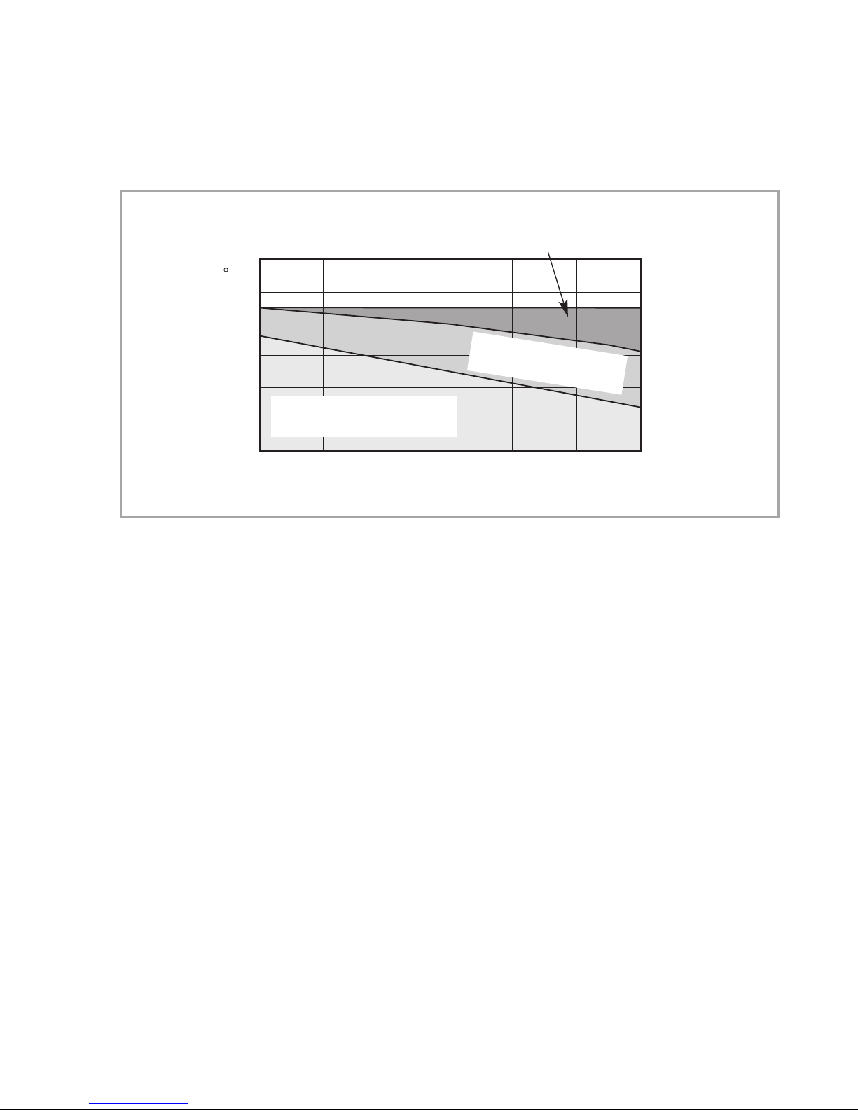
As to the cooling requirements for the separately fitted
TURBO. DRIVE see Fig. 2.1. The bottom side of the frequency converter must not be allowed to attain too high
temperatures; see technical data.
CAUTION
Max. magnetic induction levels are 15 mT, max. radioactive
radiation spec. is 10
The frequency converter must only be used in rooms within
buildings. It must not be operated in explosive gas atmospheres.
The frequency converter and the connecting lines must be
protected against exposure to sprayed and condensing
water.
During operation the frequency converter may attain
temperatures up to 75 °C. We recommend that the unit
be installed so that it can not be touched inadvertently.
Owing to the small quantity of combustible material and the
proven safety of the instrument by testing in accordance
with EN 61010, the risk through fire and burning can
almost completely be excluded.
5
rad (103Gy).
14
17200492_002_A5 - 04/2011 - © Oerlikon Leybold V
acuum
Installation
Heat sink and forced
cooling required
60
C
50
40
H
30
20
10
Ambient temperature
0
Operation possible
without additional cooling
12345
Motor current (Parameter 5)
eat sink required
(convection cooling)
6
A
Fig. 2.1 Cooling requirements for the TURBO.DRIVE 400 when fitted separately
2.3 Mounting the frequency converter
The frequency converter may be affixed with the aid of the
enclosed M4 sliding nuts. The bottom side of the frequency
converter must be cooled sufficiently.
Ensure an adequate supply and discharge of cooling air.
For special requirements please contact us.
17200492_002_A5 - 04/2011 - © Oerlikon Leybold V
acuum
15
Installation
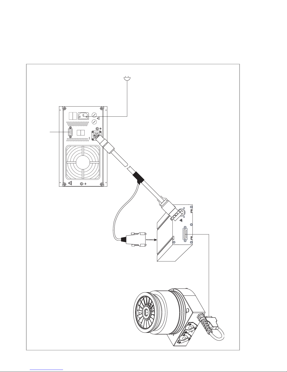
2.4 Connecting the pump
In the case of a separately fitted TURBO.DRIVE 400
connect the pump using the connecting cable.
NOTICE
WARNING
The pump may be operated only with a suitable frequency converter and suitable connecting cables.
Route all cables so as to protect them from damage.
Disconnect and connect the cable connections only
while the pump is turning no longer (green status
LED off) and with the mains power switched off (yellow power LED off). Otherwise there is the risk of
damaging the TURBO.DRIVE 400.
2.5 Connecting the power supply
The frequency converter must only be connected to
power supplies which meet the requirements for functional extra low voltage with positive isolation in accordance with IEC 364 (VDE 0100, Part 410, or local regulations) (PELV).
The power supply must meet the requirements given in
Section 1.3. Peak currents in the kHz range may be present on the DC side. The power supply should have a current limiter of the current regulated type.
NOTICE
16
17200492_002_A5 - 04/2011 - © Oerlikon Leybold V
Connect the frequency converter to the 24 V DC power
supply or to the TURBO.CONTROL 300 or to the
TURBO.POWER 300 via the 24 V DC cable.
Ensure correct polarity.
Pin 1 + 24 VDC
Pin 2 0 V
Pin 3 GND
The frequency converter is equipped with an internal 8 AT
(slow blow) fuse. It can only be replaced by Oerlikon
Leybold Vacuum staff.
Connect the power supply to the mains.
acuum
Installation
REMOTE
93 - 132 /
187 - 264
V AC,
50/60 Hz
24 V DC
L
N
D
RIVE (X3)
HEAT SINK HEAT SINK
24 V DC (X4)
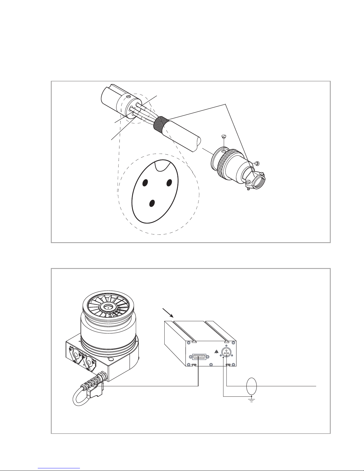
Pin 3 GND
Shielding
Pin 1 24 V
Pin 2 0 V
1
3
2
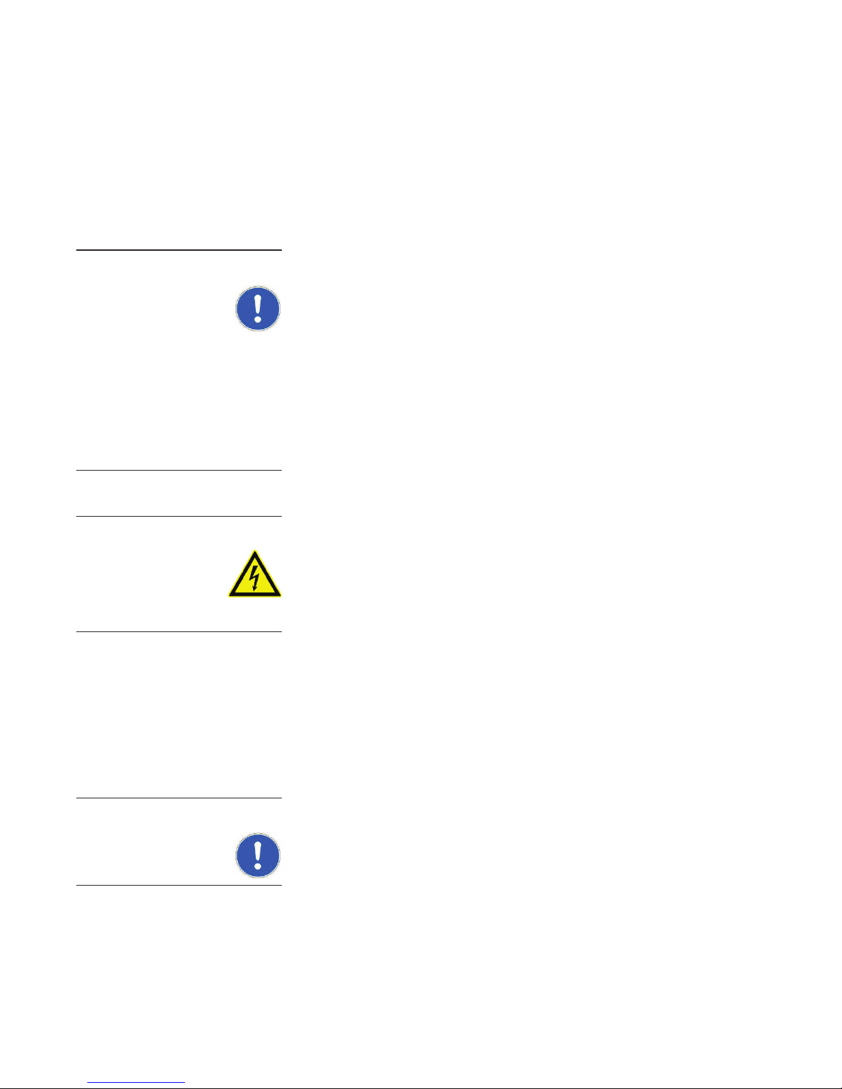
Fig. 2.2 Pin assignment of the DC connector (X4) Model Hirose HS16P-3
In the case of an integrated
connecting cable is omitted.
Fig. 2.3 Connecting the pump and the power supply
TURBO.DRIVE 400 the
DC cable,
with shielding,
max. 20 m
17200492_002_A5 - 04/2011 - © Oerlikon Leybold V
acuum
17
Installation
ON
OFF
1
0
MAINS
REMOTE IN
Programmable
logic control (PLC)
REMOTE
100 - 240 V ~
1
0
FRONT
T5 A
250 V ~
T5 A
250 V ~
REMOTE OUT
24 V POWER OUT
100 - 240 V ~
50 - 60 Hz
24 V DC Control cable
24 V DC (X4)
HEAT SINK HEAT SINK
DRIVE (X3)
REMOTE
TURBO.DRIVE 400 the
In the case of an integrated
connecting cable is omitted.
18
17200492_002_A5 - 04/2011 - © Oerlikon Leybold V
Fig. 2.4 Connecting the pump and the TURBO.CONTROL 300
acuum
 Loading...