

Page 1

UL 200
Helium Leak Detector
Cat. No.
140 00 141 00 142 00
140 01 141 01 142 10
140 10 141 10 142 11
140 11 141 11
for software version V 2.6
Technical Handbook
TH 10.211/ 8.02
Leak Detection
Vacuum Measurement
and Components
In Situ Analysis
LEYBOLD INFICON
The Instrumental Difference
TM
View our inventory
Page 2

Leybold Service
If equipment is returned to LEYBOLD, indicate whether
the equipment is free of substances damaging to health
or whether it is contaminated. If it is contaminated also
indicate the nature of the hazard. LEYBOLD must return
any equipment without a Declaration of Contaminationî
to the sender’s address (refer also to Chapter 3.1).
General
We reserve the right to alter the design or any data given
in this handbook.
The illustrations are not binding.
Notes on how to use this handbook
Important remarks concerning operational safety and
protection are emphasized as follows:
Warning Indicates procedures that must be strict-
ly observed to prevent hazards to persons.
Caution Indicates procedures that must strictly
be observed to prevent damage to, or
destruction of the UL 200 helium leak
detector.
Note
Indicates special requirements the user must comply
with.
The references to diagrams, e.g. (2/5) consist of the Fig.
No.and the Item No. in that order.
Contents
Page
1 Description . . . . . . . . . . . . . . . . . . . . . . . . . 3
1.1 General information . . . . . . . . . . . . . . . . . . . 3
1.1.1 Purpose . . . . . . . . . . . . . . . . . . . . . . . . . . . . 3
1.2 Technical data . . . . . . . . . . . . . . . . . . . . . . . . 3
1.2.1 Physical data . . . . . . . . . . . . . . . . . . . . . . . . 3
1.2.2 Electrical data . . . . . . . . . . . . . . . . . . . . . . . . 3
1.2.3 Other data . . . . . . . . . . . . . . . . . . . . . . . . . . 4
1.3 Equipment . . . . . . . . . . . . . . . . . . . . . . . . . . 4
1.3.1 Supplied equipment . . . . . . . . . . . . . . . . . . . 4
1.3.2 Accessories . . . . . . . . . . . . . . . . . . . . . . . . . 4
1.4 Technical description . . . . . . . . . . . . . . . . . . . 5
1.4.1 Forevacuum pump . . . . . . . . . . . . . . . . . . . . 5
1.4.2 Turbomolecular pump . . . . . . . . . . . . . . . . . . 5
Page
1.4.3 Mass spectrometer . . . . . . . . . . . . . . . . . . . . 5
1.4.4 Ion source . . . . . . . . . . . . . . . . . . . . . . . . . . 5
1.4.5 Separation system . . . . . . . . . . . . . . . . . . . . 6
1.4.6 Ion collector . . . . . . . . . . . . . . . . . . . . . . . . . 6
1.4.7 Electrometer amplifier . . . . . . . . . . . . . . . . . . 6
1.4.8 Mass spectrometer supply . . . . . . . . . . . . . . 6
1.4.9 Control . . . . . . . . . . . . . . . . . . . . . . . . . . . . . 6
1.4.10 Operation and remote control . . . . . . . . . . . . 6
1.5 Description of the functions of the UL 200 . . . 7
1.5.1 Vacuum Method . . . . . . . . . . . . . . . . . . . . . . 7
1.5.2 Partial Flow Method . . . . . . . . . . . . . . . . . . . 7
1.5.3 Sniffer Mode . . . . . . . . . . . . . . . . . . . . . . . . . 7
2 Operation . . . . . . . . . . . . . . . . . . . . . . . . . . 8
2.1 Installation of the instrument . . . . . . . . . . . . 10
2.1.1 Installation . . . . . . . . . . . . . . . . . . . . . . . . . 10
2.1.2 Preparations for initial start-up . . . . . . . . . . . 10
2.2 Electrical connections . . . . . . . . . . . . . . . . . 10
2.3 Start-up (first pump-down cycle) . . . . . . . . . 11
2.4 The controls and their functions . . . . . . . . . 12
2.4.1 Overview of the controls and displays . . . . . 12
2.4.2 The mains switch . . . . . . . . . . . . . . . . . . . . 12
2.4.3 Controls on the control panel . . . . . . . . . . . 12
2.4.4 Controls on the hand unit . . . . . . . . . . . . . . 13
2.4.5 Displays on the hand unit . . . . . . . . . . . . . . 14
2.5 Equipment settings (menu structure) . . . . . . 15
2.5.1 Entry of equipment parameters . . . . . . . . . . 15
2.5.2 Password . . . . . . . . . . . . . . . . . . . . . . . . . . 15
2.5.3 Menu functions (overview) . . . . . . . . . . . . . . 16
2.5.4 Description of the individual menu functions 16
2.6 Equipment connections . . . . . . . . . . . . . . . . 27
2.6.1 RS 232 C interface (SERIAL) . . . . . . . . . . . 27
2.6.2 Chart recorder outputs (RECORDER) . . . . . 27
2.6.3 Control inputs and outputs (CONTROL) . . . 27
2.6.4 Connection for accessories (OPTION) . . . . . 28
2.7 Calibration . . . . . . . . . . . . . . . . . . . . . . . . . 28
2.7.1 Internal calibration . . . . . . . . . . . . . . . . . . . . 28
2.7.2 External calibration . . . . . . . . . . . . . . . . . . . 29
2.7.3 External calibration for sniffer applications . . 29
2.8 Shutdown . . . . . . . . . . . . . . . . . . . . . . . . . . 30
3 Maintenance . . . . . . . . . . . . . . . . . . . . . . . 31
3.1 LEYBOLD service . . . . . . . . . . . . . . . . . . . . 31
3.2 Maintenance plan . . . . . . . . . . . . . . . . . . . . 31
3.2.1 Opening the UL 200 . . . . . . . . . . . . . . . . . . 31
3.2.2 Exchanging the filter mats . . . . . . . . . . . . . . 32
3.2.3 Exchanging the oil . . . . . . . . . . . . . . . . . . . 32
3.2.4 Cleaning . . . . . . . . . . . . . . . . . . . . . . . . . . . 33
3.2.5 Exchanging the fuses . . . . . . . . . . . . . . . . . 33
4 Messages . . . . . . . . . . . . . . . . . . . . . . . . . 35
4.1 Equipment messages . . . . . . . . . . . . . . . . . 35
4.2 Warnings and error messages . . . . . . . . . . . 37
4.2.1 Warnings . . . . . . . . . . . . . . . . . . . . . . . . . . 37
4.2.2 Error messages . . . . . . . . . . . . . . . . . . . . . 37
4.2.3 List of all warnings and error messages . . . 38
5 Definition of terms . . . . . . . . . . . . . . . . . . 42
2
TH 10.211/8.02 - 12/97
Page 3

1.1 General Information
The UL 200 helium leak detector is supplied
ready for operation. Even so, we recommend
that you carefully read the Operating Instructions and the Technical Handbook so as to
ensure optimum operating conditions right
from the start.
This handbook contains important information on functions, installation, start-up and operation of the UL 200.
Unpack the UL 200 helium leak detector immediately
after it has been received even if it is to be put into operation at some later date.
Examine the shipping container for any external damage.
Completely remove all packaging materials.
Note
Retain the shipping container and the packaging materials in the event of possible complaints concerning any
damages.
Check that the UL 200 helium leak detector is complete
(see Section 1.4) and Carefully subject to a visual inspection.
If any damage is discovered please immediately inform
the forwarding agent and the insurers.If it is required to
exchange the damaged part please contact our orders
department.
1.1.1 Purpose
The ULTRATEST UL 200 is a helium leak detector.This
instrument may be used to localise and quantify leaks in
test samples.
- when these have been evacuated first and are sprayed
with helium on the outside. For this it is required that a
vacuum connection is provided between the UL 200
and the test sample.
- In the case of small test samples, these may be evacuated by the UL 200 alone (vacuum method); in the
case of larger volumes, the test samples must be evacuated together with a further pump system (par tial
flow vacuum method).
- when there is present in the test samples a helium
overpressure and when the test sample is searched
from the outside with a sniffer probe (sniffer method).
Caution The UL 200 must not be operated while
standing in water or when exposed to
drip water.The same applies to all other
kinds of liquids.
Caution Avoid contact of the UL 200 with bases,
acids and solvents as well as exposure
to extreme climatic conditions.
1.2 Technical Data
1.2.1 Physical Data
Operation of the UL 200 helium leak detector is - as a
rule - based on the counterflow principle.
Lowest detectable helium leak rate
Vacuum mode ≤ 5·10
-11
mbar·l·s
-1
Sniffer mode ≤ 1·10-7mbar·l·s
-1
Greatest helium leak rate which can be displayed
0.1 mbar·l·s
-1
Measurement range 9 decades
Detectable masses 2, 3 and 4
Mass spectrometer 180 ° sector field
Ion source 2 cathodes; iridium / yttrium
Max. inlet pressure (in measurement mode) 3 mbar
Equipment-specific processing time
time constant of the leak rate signal
(blanked off, 63 % of the final value) < 1 s
Pumping speed at the inlet S ≥ 1 l·s-1FINE
S ≥ 0.6 l·s-1GROSS
Temperature coefficient ≤ 1 % / °C (10 to 40 °C)
Test port DN 25 KF
Time until ready for operation < 3 minutes
1.2.2 Electrical Data
Mains voltage (fixed) 100 V ± 10 %; 50 / 60 Hz
110 - 120 V ± 10 %; 60 Hz
220 - 240 / 230 V ± 10 %; 50 / 60 Hz
Power consumption ≤ 350 W
Type of protection IP 30
Mains cord 2.5 m
3
TH 10.211/8.02 - 12/97
1 Description
Page 4

1.2.3 Other Data
Noise level < 54 dBA
Valves solenoid
Dimensions (W x H x D) in mm 490 x 430 x 250
Weight 37 kg
Permissible ambient temperature
(during operation) 10 °C to 40 °C
Permissible storage temperature - 40 °C to 60 °C
Max. rel. humidity 80 % non-condensing
1.3 Equipment
1.3.1 Supplied Equipment
UL 200 helium leak detector, ready for operation.
Mains cord, 2.5 m long
Operating Instructions
- ULTRATEST UL 200 GA 10.211
- Technical Handbook TH 10.211
- Spare Parts List ET 10.211
- Interface Description UL 200 SB 10.211
- TRIVAC D 2,5 E GA 01.600
- Forms, Declaration of Contamination
Blank flange DN 25 KF
Quick clamping ring DN 25 KF
DN 25 KF gasket
DN 25 KF centering ring
1 set of fuses
1 set of filter mats
2 L-type screwed connections (hose connections)
1 hose nozzle
1.3.2 Accessories
Cat. No./ Ref. No.
Sniffer line for UL 200, 4 m 140 21 or 140 24
Retrofit calibrated leak 140 23
Extension cord for the hand unit, 8 m 140 22
Partial flow pump set 140 20; 140 25
140 26; 140 27; 140 28
QT 100 helium sniffer 155 94
Sniffer line for QT 100, 20 m long 155 76
Transport boy 140 97
Cart 200 140 93
Transport case 140 96
Set of connection plugs 200 28 782
PC software „LeakWare“ 140 90
4
TH 10.211/8.02 - 12/97
Page 5
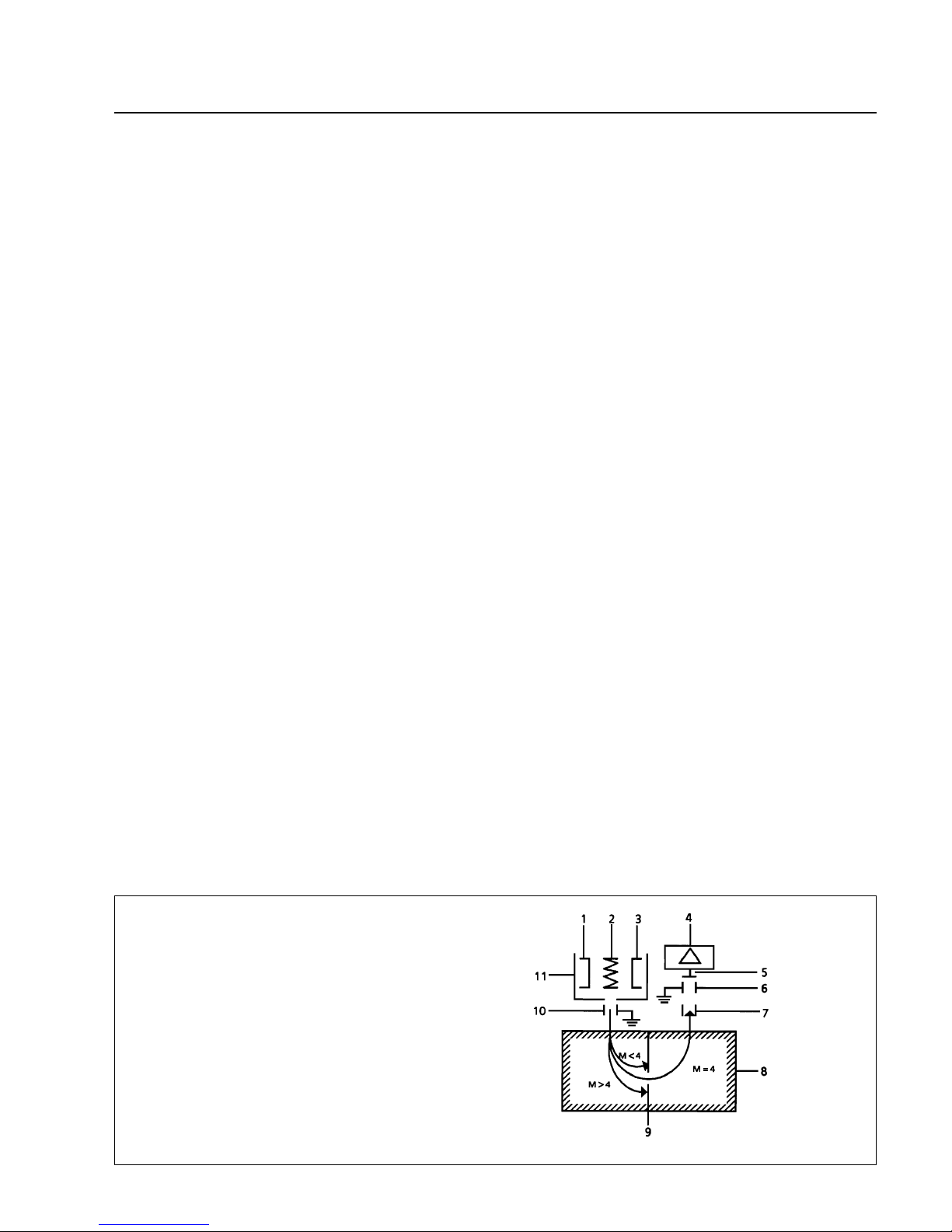
1.4 Technical Description
The UL 200 is capable of detecting and quantifying helium test gas flowing into a test sample having a leak by
means of a selective mass spectrometer. Its operation is
based on the counter flow principle, i.e. inflowing helium
diffuses against the gas flow being pumped by the turbomolecular pump into the mass spectrometer whereas
heavier gases, water vapour in par ticular, are held back.
A cold trap using liquid nitrogen is thus not required.
The ULTRATEST UL 200 is composed of the following
principal subassemblies:
- a 180 ° magnetic sector field mass spectrometer -the
detection system
- a high vacuum pump system
- a valve block for controlling the gas flow
- the corresponding electrical and electronic subassemblies for supplying power and for signal conditioning. A
detachable hand unit and a control panel on the instrument itself belong to this category.
1.4.1 Forevacuum Pump
A TRIVAC D 2.5 E rotary vane pump in the UL 200 serves as the forevacuum pump (2/16). All data and further
information on this pump are given in the Operating
Instructions GA 01.600.
The backing pump generates the forepressure required
for operation of the turbomolecular pump.
In the vacuum mode the test sample is also evacuated,
whereas in the sniffer mode the necessary gas flow is
generated.
1.4.2 Turbomolecular Pump
A TURBOVAC TMP 35 LS is used in the ULTRATEST UL
200.The turbomolecular pump generates the high vacu-
um necessary for operation of the mass spectrometer.
Heavier gases are evacuated owing to the high compression, whereas the helium test gas is able to diffuse
upstream into the mass spectrometer.
This pump offers two special features:
a) Ahead of the turbomolecular stage (high pumping
speed) there is a screw-type stage which provides a
high compression.Thus the UL 200 may switch to
the measurement mode already at high intake pressures.
b) The TMP 35 LS has a side connection.Thus the
high pumping speed may be utilised in the FINE
mode at the inlet of the leak detector.This considerably reduces the response time of the leak detector.
(Response time = volume of the test sample / effective pumping speed for helium)
The compression capacity of the TMP and the pumping
speed of the forevacuum pump determine the sensitivity
of the entire arrangement.
1.4.3 Mass Spectrometer
The mass spectrometer, MS (2/7) is chiefly composed of
the ion source, the magnetic separator and the ion
collector (1/5).
The ion source ionizes neutral gas particles and generates from these an ion beam.The positively charged ions
are accelerated out of the ion source and then enter the
magnetic field. Here they are deflected along a circular
path, the radius of which depends and the mass-to-charge ratio of the ions.Only the helium ions are able to meet
the separating conditions and arrive at the ion collector,
where their presence can be measured as a current by
an electrometer amplifier.
1.4.4 Ion Source
Electrons having an energy of 80 eV are used in the ion
source.
The electrons which are emitted by the hot cathode (1/1)
5
TH 10.211/8.02 - 12/97
Key to Fig. 1
1 Cathode 1
2 Anode
3 Cathode 2
4 Amplifier
5 Ion collector
6 Shield for ion collector
7 Suppressor
8 Magnetic field
9 Inter mediate or ifice
10 Extractor orifice
11 Guard ring
Fig. 1 Schematic diagram of the mass spectrometer
Page 6

are attracted by the positively charged anode (1/2). But
they do not immediately impinge on the anode (1/2);
instead they oscillate to and fro several times until they
finally arrive at the filament of the anode (1/2).
On this path they ionize the gas atoms by impact.These
ions are extracted from the ion source by a groundconnected extractor orifice (1/10) and enter the magnetic separation system.
In order to avoid deposits of polymerized hydrocarbons
(insulating layers which ma y impair sensitivity) the anode
is heated while the UL 200 runs up.
Due to the operating temperature of the ion source
(cathode heater), this is no longer required after the
instrument has run up and the anode heater is then switched off for this reason.
Cathodes (1/1) and (1/3) are made of iridium tape which
is coated with yttrium oxide.Due to this coating, the operating temperature of the iridium filaments is much lower
compared to tungsten filaments, and these offer excellent resistant to burnout, imbrittlement, oxygen, water
vapour and hydrocarbons.
1.4.5 Separation System
A magnetic sector field (1/8) with 180 ° deflection is used
as the separating system. Due to the inhomogeneous
magnetic field perpendicular to the ion beam, additional
focusing of the ions is attained in this direction (Z-focusing) resulting in a high sensitivity.
Unwanted ions from other gases are kept away in addition by means of the intermediate orifice (1/9).
1.4.6 Ion Collector
The ion collector (1/5) is composed of a tube-shaped
suppressor and the actual collecting plate.
The suppressor (1/7) carries a positive potential which is
slightly less than the anode potential. It is the purpose of
the suppressor to prevent scattered ions which have a
lower nominal energy from arriving at the collector.This
improves resolution at low detection rates.
The impinging ions are collected by the collecting plate
where they are neutralized. The corresponding current
flows into the connected amplifier.
1.4.7 Electrometer Amplifier
The electrometer amplifier amplifies the current which is
generated on the ion collector of the mass spectrometer.
Gain of this amplifier can be switched ov er in four stages .
The control assembly is responsible for the switching
over and processing of the analogue output signal.The
detection limit in the most sensitive range amounts to
approximately 1·10
-15
A.
1.4.8 Mass Spectrometer Supply
The subassembly generates all the voltages and currents required for operation of the mass spectrometer:
- anode heating voltage
- cathode heating voltage
- anode voltage
- suppressor voltage
Errors in the mass spectrometer are detected and sig-
nalled to the control assembly. The control assembly
monitors the mass spectrometer supply.
1.4.9 Control
The control assembly is the central assembly of the leak
detector’s electronics. All other subassemblies are controlled and monitored by this assembly. The microprocessor which is located here is thus continuously informed about the status of the entire leak detector and can
respond accordingly. In order to accept commands from
the operator and to output measured values and messages, the control subassembly is linked to the operating
and display subassembly.
1.4.10 Operation and Remote Control
These two subassemblies are used to communicate with
the operator.They accept commands from the key pad
and output measurement results and messages via the
display components.
6
TH 10.211/8.02 - 12/97
Page 7

1.5 Description of the
Functions of the UL 200
The mass spectrometer (2/7) only operates under high
vacuum conditions, i.e. the pressure here must always
remain below 10-3mbar.This vacuum is generated b y the
turbomolecular pump (2/6) with the support of the rotar y
vane pump (2/16). Except dur ing the evacuation phase,
the valve (2/3) between these two pumps alw a ys remains
open so that this is ensured. In this state the UL 200
reverts to the standby mode; after completion of run-up,
for example. All other valves are then closed.The pressure pV between the two pumps is measured with a Pirani gauge (2/4) and this pressure lies in the range between 3 to 10-3mbar while in the measurement mode.
This pressure must not exceed a value of 3 mbar as
otherwise the turbomolecular pump will not be capable of
maintaining the vacuum in the mass spectrometer.
1.5.1 Vacuum Method
For the purpose of leak detection on a test sample (vacuum method), the sample has to be evacuated so that
helium which is sprayed on to the outside, can enter
through any leaks due to the pressure differential for
detection by the leak detector.
The test sample is evacuated - START push-button (5/3)
- by the rotary vane vacuum pump (2/16).In the case of
larger test samples an additional external partial flow
pump (2/15) with a corresponding linking valve (2/12)
may be connected in parallel as required.
Inlet valve (2/14) is opened so that the evacuation may
take place.At the same time valve (2/3) is closed in order
to prevent an unacceptable pressure increase in the
mass spectrometer.
In this context (valve (2/3) closed) the turbomolecular
pump is operated without being supported by the rotary
vane pump.Since generally no gas is pumped out of the
mass spectrometer, pVremains constant or increases
only slowly.
The condition for the evacuation process described here
is maintained until the inlet pressure pE(2/13) has dropped ≤ 3 mbar.Now the valves (2/5) and (2/3) are opened
and (2/14) is closed. Possibly present helium may now
flow upstream against the pumping direction of the turbomolecular pump (2/6) into the mass spectrometer
where it is detected. This measurement mode is called
GROSS.In this mode, leak rates down to 10-9mbar·l·s
-1
can be detected.
Since the rotary vane vacuum pump (2/16) continues to
evacuate the test sample via valves (2/3) and (2/5) the
inlet pressure pEwill continue to drop.When the pressure drops below pE< 0.2 mbar, the UL 200 will switch to
the FINE mode, i.e. valve (2/5) closes and valve (2/8)
opens so that the gas flow enters the turbomolecular
pump (2/6) at the side.This offers two advantages:
a) A par t of the high pumping speed of the turbomole-
cular pump remains available f or further ev acuation of
the test sample.The response time of the leak detector is reduced (response time is inversely proportional
to pumping speed).
b) The advantages offered by the counterflow principle
can still be utilized.
In the FINE mode the full sensitivity of the UL 200 is reached.
When the leak detection process is stopped - STOP
push-button (5/2) - all valves except valve (2/3) are closed.
Valve (2/10) is opened during venting.
1.5.2 Partial Flow Method
In the partial flow mode the test sample is additionally
evacuated by an auxiliar y pump. Using the optional partial flow pump set (see Chapter 1.3.2) offers to the user
the following advantages:
- faster response
- entry into the measure mode already at an inlet pressure of the 1000 mbar
- faster venting of large test objects
1.5.3 Sniffer Mode
The UL 200 may simply be conver ted into a sniffer leak
detector via two rugged sniffer lines (Cat. No. 140 21 or
140 24).
For this the KF flange of the sniffer line is connected to
the inlet flange (3/2) and the sniffer mode is selected
through menu item 2 (see Chapter 2.5.4). After pressing
START, the inlet valve (2/14) opens. The sniffer lines
have been designed in such a way that the UL 200 is
operated in the FINE mode (as described in Chapter
1.5.1).
A calibration according to Chapter 2.7.3 is recommended.
In the measurement mode the helium present in the
ambient air is now indicated as the leak rate (about
2·10-6mbar·l·s-1). Smaller leaks may be detected by
pressing the ZERO push-button (Chapter 2.4.4).
7
TH 10.211/8.02 - 12/97
Page 8
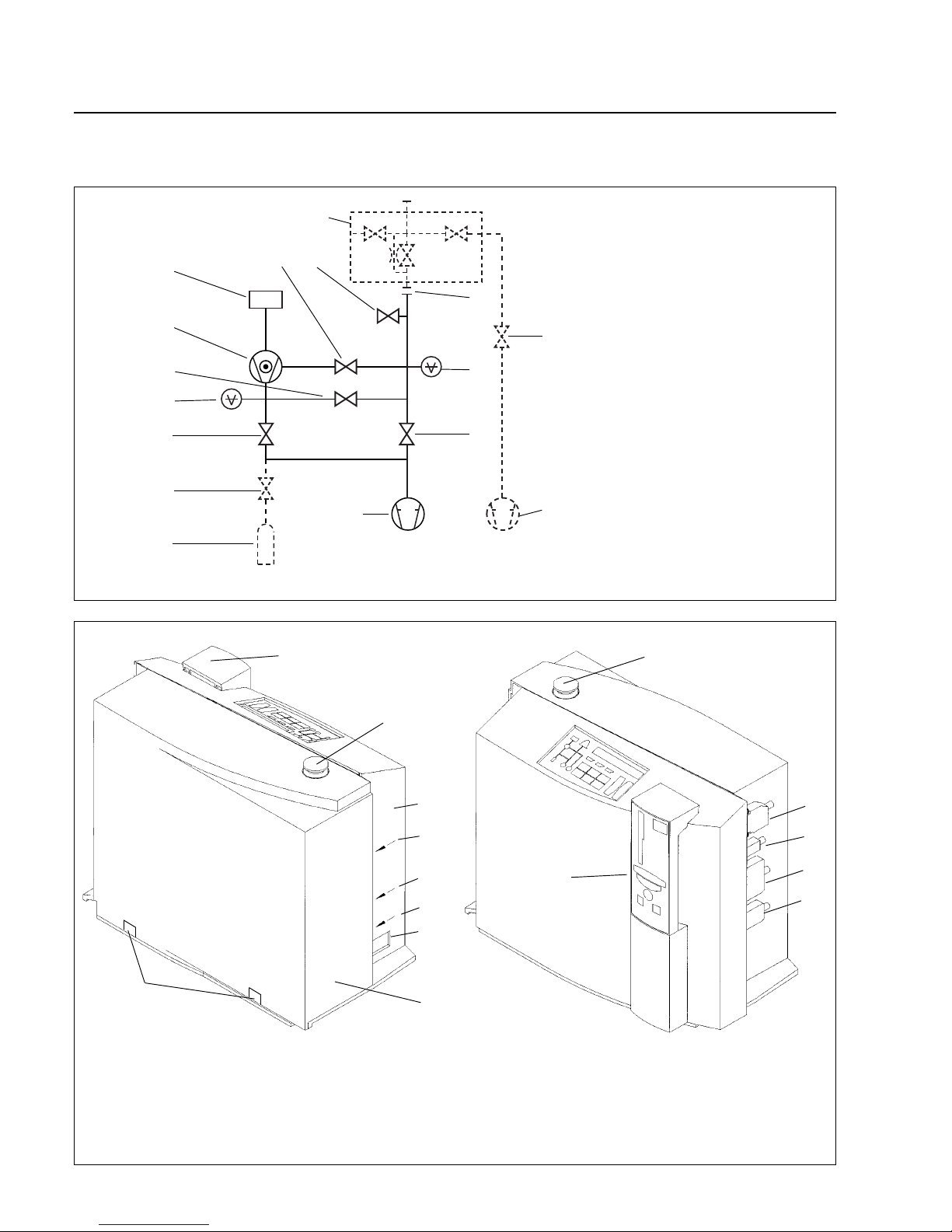
8
TH 10.211/8.02 - 12/97
2 Operation
Fig. 3 Instr ument views
Key to Fig. 3
1 Hand unit
2 Test connection
3 Electronics cover
4 VENT input
5 Connection for exhaust line
6 Gas ballast connection
7 Mains switch with mains fuses
8 Mechanical cover
9 Openings for removal of the
mechanical cover
10 RS 232 C interface (SERIAL)
11 Chart recorder output (RECOR)
12 Control inputs and outputs
(CONTROL)
13 Connection for the
Accessories (OPTION)
4
5
6
7
8
9
1
2
3
1
2
10
12
11
13
Mechanical side
Electronics side
MS
5
6
8
9
1
2
3
4
12
11
13
15
14
16
10
7
Key to Fig. 2
1 Calibrated leak (optional)
2 Valve for the calibrated leak (V 7)
3 Inlet valve (V 2.a)
4 Pirani gauge p
V
5 Inlet valve (V 2.b)
6 Turbomolecular pump (TMP)
7 Mass spectrometer
8 Inlet valve (V 4)
9 Partial flow pump set (optional)
10 Venting valve (V 3)
11 Connection flange
12 Exter nal partial flow valve (V 8) (optional)
13 Pirani gauge p
E
14 Evacuation valve (V 1)
15 Exter nal partial flow pump (optional)
16 Forevacuum pump
Fig. 2 Vacuum diagram
Page 9
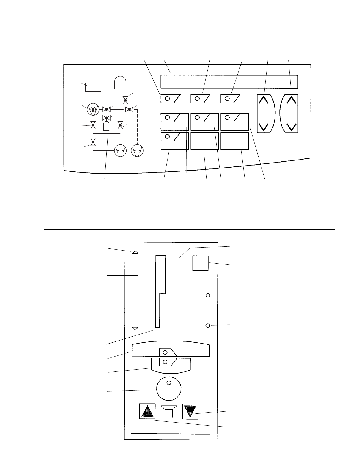
9
TH 10.211/8.02 - 12/97
Fig. 4 Control panel
Key to Fig. 4
1 LED for trigger 1
2 LCD display
3 LED for trigger 2
4 LED for trigger 3
5 SCROLL push-button
6 VALUE push-button
7 MENU push-button
8 ENTER push-button
9 CAL push-button
10 CLEAR push-button
MANUAL
SERVICE
CAL
MENUE
ENTER
CLEAR
TRIG 1
TRIG 3
TRIG 2
SCROLL
VALUE
1
2
3
5
4 6
11 MANUAL push-button
12 SERVICE push-button
13 Vacuum diagram (simplified)
L 1 to L 9 light emitting diodes
7
10
9 8
111213
L3
L2
L1
L4
MS
L6
L5
L8
L7
L9
Key to Fig. 5
1 ZERO push-button
2 STOP / VENT push-button
3 START push-button
4 LED-Bargraph display
5 Underflow display
(under range)
6 Leak rate scale
7 Overflow display
(over range)
8 Scale for the pressure in
the test sample
9 Exponent
10 MANUAL LED
11 LOCK LED
12 Acoustic signal quieter
13 Acoustic signal louder
START
MANUAL
LOCK
ZERO
STOP/VENT
mbarl/s
10
9
8
7
6
5
4
3
2
1
0,9
0,8
0,7
0,6
0,5
0,4
0,3
0,2
0,1
mbar
400
100
10
1
0,1
-8
9
7
6
8
3
2
4
5
12
11
1
10
13
Fig. 5 Hand unit
Page 10

2.1 Installation of the
Instrument
2.1.1 Installation
Caution In order to ensure adequate ventilation
of the UL 200, a space of at least 10 cm
must be kept unobstructed to the sides.
Also the clearance at the rear must be
no less than 10 cm. Moreover, the ventilation slits at the holder for the hand unit
under the UL 200 as well as under the
recess for the handles must not be
covered.For this reason you must never
place the UL 200 on thick and soft mats
(foam rubber, for example).
The UL 200 is capable of reliable operation under normally encountered industrial conditions (for these refer
also to Chapter 1.2.3).
2.1.2 Preparations for Initial Start-Up
The UL 200 is supplied ready for operation.
Caution Before operating the instrument for the
first time, you must remove the yellow
shipping seals on the gas ballast connection (3/6) and the exhaust connection (3/5). Retain the shipping seals in
case you want to ship the equipment at
some later date.
When operating the UL 200 in closed rooms and especially when detecting leaks in the sniffer mode on large test
objects or when actuating the pump’s gas ballast, you
should connect the „EXHAUST“ (3/5) connection to a line
leading to the outside of the building. In rooms where the
helium concentration significantly exceeds 5 ppm, the
connection of fresh air feed lines is also recommended.
Air which is free of helium should be supplied via a hose
line which is connected to the „VENT“ connection (3/4).
Additionally, the gas ballast connection „GAS BALLAST“
(3/6) should also be supplied with fresh air.
With the aid of the angled bracket which is supplied with
the instrument it is possible to easily connect plastic
tubes (6 mm outside diameter and 4 mm inside diameter).
Note
Before starting the instrument for the first time, check the
oil level in the forevacuum pump.
In order to remove the mechanical cov er , turn the UL 200
first in the way as shown in the left part of Fig.3. Insert a
flat blade screwdriver into the openings (3/9) in order to
disengage the mechanical cover (3/8) at the lower side.
For this also refer to Chapter 3.2.1 with figures 6 and 7.
Then pull the mechanical cover upwards to the stop and
take it away to the front (please refer to the enclosed
operating instructions for the pump when wanting to
check the oil level).
2.2 Electrical Connections
Note
In general, the regulations as laid down in the currently
valid VDE 0100 must be observed.
Caution Before connecting the instrument to the
mains you must make sure that the
mains voltage rating of the instrument
coincides with the locally available
mains voltage.
The mains voltage rating for the instrument can be read
off from the name plate under the handle at the mains
switch.
The mains voltage setting of the UL 200 is fixed and can
not be changed.
A separate fuse for each of the mains conductors has
been integrated into the mains socket (3/7).
The mains voltage is applied to the instrument via the
detachable mains cable which is supplied with the instrument. A mains socket is available for this purpose at the
left hand side of the instrument.
Caution Only 3-core mains cables having a pro-
tective ground conductor must be used.
Operation of the instrument where the
ground conductor has been left unconnected is not permissible.
10
TH 10.211/8.02 - 12/97
Page 11

TH 10.211/8.02 - 12/97
11
No.
1
--
-- --
----
--
--
--
--
--
--
2
3
4
5
6
7
9
10
11
12
13
14
8
Activity Response Display on the control panel Fig. 4 Display on the hand unit Fig. 5
Check the mains voltage and
connect the mains cable;
Set the mains switch (3/7) to
the „1“ position
Press the START push-button
(5/3) briefly
--
-- --
--
--
----
Press the STOP push-button
(5/2) for over 1.5 s
Open the test port (3/2)
Disconnect the test sample
Connect the test sample
Press the START push-button
(5/3) briefly
Press the STOP push-button
(5/2) for over 1.5 s
Spray the test sample with
Indication of operational readiness by an acoustic signal.
The first measurement readout is obtained at an inlet
pressure for p
E
< 3 mbar
(GROSS mode).)
When the inlet pressure
p
E
< 0.2 mbar the instrument
changes to the FINE mode.
Starting of the stopping process.
Starting of the venting process.
Display of the leak rate
The first measurement readout is obtained at an inlet
pressure for pE< 3 mbar
(GROSS mode).)
When the inlet pressure
pE< 0.2 mbar the instrument
changes to the FINE mode.
Starting of the measurement
process.
Pumpdown of the dead volume at the inlet.
Initiation of the measurement
process. Pumpdown of the
dead volume at the inlet.
Starting of the stopping process.
Starting of the venting pro-
Running up of the forevacuum pump and the turbomolecular pump.Pumpdown of the
detection system. The automatic self test starts. The
emission is switched on.
„LEYBOLD INFICON“
„UL 200 Version x.x“
Light emitting diode L2 (4/13) is on.
Light emitting diode L3 (4/13) flashes.
„Running Up TMP:1050 Hz“
„Emission OFF ==> ON“
Light emitting diode L4 (4/13) flashes.
„Standby“
Light emitting diodes L2, L3 and L4
(4/13) are on.
„LR = 3.1E-09 PE = 1.5 E+0“
Light emitting diodes L2, L3, L4 and
L9 are on.
Light emitting diode L9 is off.
Light emitting diodes L2, L3, L4 and
L5 are on.
„Vent“
Light emitting diode L5 is off.
Light emitting diode L7 is on.
Light emitting diodes L2, L3 and
L4 are on.
„Vent“
Light emitting diode L5 is off.
Light emitting diode L7 is on.
Light emitting diodes L2, L3 and L4
are on.
„LR = 5.1 E-07 PE = 1.5 E-1
„LR = 3.1E-09 PE = 1.5 E+0“
Light emitting diodes L2, L3, L4 and
L9 are on.
Light emitting diode L9 is off.
Light emitting diodes L2, L3, L4 and
L5 are on.
Light emitting diode L7 is off.
„Evacuation PE = 3.5 E+1 “
Light emitting diodes L3 and L4 are
on.
Light emitting diode L2 is off.
Light emitting diode L9 is on.
„Evacuation PE = 3.5+1 “
Light emitting diodes L3 and L4
are on.
Light emitting diode L2 is off.
Light emitting diode L9 is on.
All display components are on.
ROM and RAM test.
Decimal point (5/9) flashes.
Test of the display components.
TMP speed is indicated on the
bargraph display (5/4).
Display of helium background or
the detection limit on the bargraph display (5/4) and exponent
(5/9).
START display (5/3) is on;
Display of leak rate (5/6) on the
bargraph display (5/4) and exponent (5/9).
--
Display of helium background on
the bargraph display (5/4) and
exponent (5/9);
Vent LED (5/2) is on.
Display of helium background on
the bargraph display (5/4) and
exponent (5/9);
Vent LED (5/2) is on.
START display (5/3) is on;
Display of leak rate (5/6) on the
bargraph display (5/4) and exponent (5/9).
START display (5/3) flashes;
Display of inlet pressure (5/8) on
the bargraph display (5/4).
START display (5/3) flashes;
The pressure in the test sample
(5/8) is indicated on the bar
graph display (5/4).
Blank off the connection flange (3/2)
Leak rate on bargraph display
(5/4) and exponent (5/9).
2.3 Start-Up (First Pump-Down Cycle)
Page 12

2.4 The Controls and their
Functions
2.4.1 Overview of the Controls and
Displays
Except for the mains switch, all controls and displays are
located on the control panel (Fig.4) and on the hand unit
(Fig. 5)
The hand unit is detachable and linked to the instrument
via a connecting cable.Magnets have been built into the
hand unit, so that it may easily be attached to any
magnetizable surface. If required, the connection cable
of the hand unit leading to the UL 200 can be extended
(extension cable Cat.No. 140 22).
The controls and displays are shown in Fig.5.
The control panel on the UL 200 (Fig. 4) also contains
the corresponding menu and function push-buttons.
These are described in Chapter 2.4.3.
2.4.2 The Mains Switch
Operation of the mains switch (3/7) switches the entire
instrument on or off.
2.4.3 Controls on the Control Panel
MANUAL push-button
Via the MANUAL push-button (4/11) it is possible to
switch the manual ranging feature on and off. Once this
function has been selected it is then possible to enter the
display range for the leak rates (exponent) through the
VALUE push-button (4/6).
When pressing the MANUAL push-button (4/11) the following happens:
The LED in the MANUAL push-button (4/11) and the
MANUAL LED (5/8) on the hand unit come on.
The exponent (5/9) on the hand unit is frozen.When the
leak rate changes it is only required to observe the bargraph display (5/4).
In case of a range overflow, the upper arrow (5/7) at the
bargraph on the hand unit comes on and in the case of
range underflow , the low er arrow (5/5) at the barg raph on
the hand unit comes on.
The range of the exponent displayed by the LCD display
(4/2) is also restricted.The same applies to the dynamic
range of the chart recorder signal at the RECORDER
output (3/11) (see description for menu item 13). The
analogue voltage at pin 4 is constant. Only the signal at
pin 1 may be used for logging of the change in the leak
rate.
Note
The trigger thresholds (menu item 1) should fall into the
range of the bargraph display.Trigger levels outside the
range of the bargraph display are not usable in the case
of manual range selection.
The LED in the MANUAL push-button is not on and the
MANUAL status indicator (5/10) is off:
The range is selected automatically. The full measurement range is available.
SERVICE push-button
Pressing of the SERVICEpush-button (4/12) activ ates or
deactivates the service menu (see Chapter 2.5). When
the service menu has been selected, the status indicators (4/7) and (4/12) come on. If the automatic functions
have been switched off in the service menu (service
menu item 70) the UL 200 will be restarted after the service menu has been exited, i.e. all monitoring and automatic functions are switched on again.After this, the
UL 200 will be running in the Standby mode.
CAL push-button
Pressing the CAL push-button (4/9) starts a calibration
process which may be run either in connection with an
internal calibrated leak (optional) or an external calibrated leak (see Chapter Calibration).The UL 200 will then
control everything else on its own and will inform the
operator via the LCD display (4/2).The UL 200 autonomously decides whether to use the internal calibrated
leak or external calibrated leak which is connected to the
test port (3/2), depending on the instrument mode at the
time of the key-press.
Pressing of the CAL push-button in the measurement
mode: external calibration.
Pressing the CAL push-button in the Standby/Vent
mode: runs an internal calibration, provided
an internal calibrated leak has been
built-in.
The process differs for the different operating modes. If
the calibration process is to be performed with an external calibrated leak, then the calibrated leak must be
connected to the inlet or the test sample before operating
the push-button. Switchover between external and internal calibrated leak is possible by operating the START
(5/3) and STOP / VENT (5/2) push-buttons.
The calibration process may be cancelled by pressing
the CAL push-button (4/9) or the CLEAR push-button
(4/10).
LED in the push-button is on: calibration process is
active.
LED in the push-button is off:calibration process is inactive.
12
TH 10.211/8.02 - 12/97
Page 13

TH 10.211/8.02 - 12/97
13
CLEAR push-button
The CLEAR push-button (4/10) is used to cancel processes and functions which have been started. Moreover, this push-button may be used to acknowledge warnings and error messages.
Also this push-button may be used to reset a v alue which
has been changed through VALUE in a menu.
ENTER push-button
The ENTER push-button (4/8) is used to acknowledge
and accept parameters which have been set up on the
UL 200.
If several parameters can be changed in a single menu
line, pressing of this push-button advances to the next
parameter.
When the parameter is being accepted, the message
„Updating Parameter“ is displayed briefly or the next
parameter is indicated.
MENU push-button
The MENU push-button (4/7) permits many entries
though which instrument settings can be made or for
running of special instrument functions. For this also
refer to Chapter 2.5.
Pressing the MENU push-button (4/7) lets the instrument
enter the menu mode and this mode can be exited by
pressing the MENU push-button once more.
After pressing the MENU push-button, that menu line
which was active upon leaving the menu mode before is
displayed.The desired menu line is selected by pressing
the SCROLL push-button (4/5).
Within a menu line, the settings or values are changed
by pressing the VALUE push-button (4/6).
Each change which is made within a menu line must be
acknowledged by pressing the ENTER push-button
(4/8). Otherwise the changed value will not be accepted
by the UL 200.
LED is the push-button is on: menu mode is active.
LED in the push-button is off: menu mode is inactive.
SCROLL push-button
The SCROLL push-button (4/5) permits the selection of
a menu items. Also refer to Chapter 2.5.1.
VALUE push-button
With the aid of the VALUE push-button (4/6) it is possible to change settings or values. Only the parameters
which flash can be changed by operating the VALUE
push-button. Also refer to Chapter 2.5.1.
2.4.4 Controls on the Hand Unit
An overview of the controls on the hand unit is given in
Fig. 5.
START push-button
Based on the operating modes Standby or Vent of the UL
200, the START push-button (5/3) is used to start the
measurement mode by evacuating the connected test
sample. Here the UL 200 will operate either with automatic ranging or it will only display the measured values
within a fixed range which has been selected by the operator (Manual).
The status of measurement readiness is indicated to the
operator by a green LED at the START push-button.
During the pumpdown phase this LED flashes. As soon
as the status of measurement readiness has been reached, this LED stays on continuously.
When pressing the START push-button in the Standby
mode, the internal Zero level is taken over anew, provided the UL 200 has been running in the Standby or Vent
status for at least 10 s.
STOP / VENT push-button
The STOP / VENT push-button (5/2) has two different
functions, depending on how long it is pressed:
STOP function
Based on the measurement mode of the UL 200, a
brief press of the STOP push-button (5/2) interrupts
the evacuation process of the test sample and the
measurement mode is interrupted.The duration of this
key press must be no longer than the time which is
defined in menu item 22 (see Chapter 2.5.4). The
default time is 1.5 s. The UL 200 will return to the
Standby mode, i.e. all valves except valve V2a (2/3)
are closed. This condition is indicated to the operator
by the green LED in the START push-button (5/3)
which is turned off.
After pressing the STOP / VENT push-button (5/2) the
LCD display (4/2) will indicate the message „Standby“.
VENT function
When pressing the STOP / VENT push-b utton (5/2) f or
a period of time which exceeds the time as defined in
menu item 22 (1.5 s default), the connected test sample is vented as soon as this time has elapsed.This is
done by opening of the venting valve V3 (2/10). This
operating mode is indicated to the operator by the
green LED in the STOP / VENT push-button which
comes on.
The venting valve may be closed again by pressing
the STOP / VENT push-button briefly once more.The
UL 200 will then return to the Standby mode. The
„VENT“ display is turned off.
In the Standby mode and after a transitional period of
Page 14

10 s, the helium background of the UL 200 is continuously monitored.This helium background may be indicated when selecting menu function „21:System BG display on“.The helium background determination process
takes up to 10 s depending on the sensitivity setting.The
helium background serves as the Zero level for the subsequent measurements.
When the START push-button (5/3) is pressed before
this process has been completed, the Zero determination process is cancelled and the previous Zero value will
be used once more.
The automatic gas ballast control is also monitored
during the Standby mode.The monitoring facility to control the gas ballast valve will start 30 s after the UL 200
has returned to the Standby mode (see description for
menu item 3).
ZERO push-button
A constant leak rate reading may be suppressed by
pressing the ZERO push-button (5/1), i.e. a constant
helium background within a test sample.This push-button is only active in the measurement mode.
The exponent on the hand unit is retained in the case of
„Zero“ when the leak rate display always remains at the
upper decade of the bargraph display. If the leak rate is
indicated in the lower decade, the exponent is decremented by one in the case of „Zero“.Thus the displayed
leak rate can always be suppressed by at least one
decade so as to increase resolution.
Example
A leak rate of 4.1·10-8mbar·l·s-1can be displayed in two
ways on the hand unit:
a) The exponent indicates -8 and the narrow part of the
bargraph display is fully on and the wider section is
on up to number 4.
b) The exponent indicates -7 and only the lower narrow
section of the bargraph display is on up to number
0.4.
In both cases the exponent -8 and the bargraph display
is dark after pressing of ZERO.
After the ZERO push-button (5/1) has been pressed, the
currently indicated leak rate is stored as the „Zero level“
without changing the internal Zero level which has been
determined by the Zero determination process.
Only values above this Zero level are indicated so that
resolution of the displayed measurement signal is improved.
Note
It is not possible to reduce the detection limit of the
instrument by pressing the ZERO push-button (5/1).
The ZERO function is cancelled by pressing the ZERO
push-button once more. The Zero function is also can-
celled automatically as soon as the STOP / VENT pushbutton (5/2) is pressed.
The ZERO function has an effect on all output devices
such as remote control, LCD display, chart recorder, triggers and RS 232 interface.
Should the helium background which has been suppressed with the aid of the ZERO push-button change in such
way that no measured value is indicated for over
t = 5 s, then the Zero level is readjusted automatically.
Acoustic signal
The acoustic signal is used to indicate the leak rate. An
acoustic signal is also generated in the case of error
messages. For details please refer to the description of
menu item 18 in Chapter 2.5.4 and in Chapter 4.2.
The volume of the acoustic signal can be increased by
operating the push-button (5/13) to the left of the loudspeaker. With the push-button (5/12) to the right of the
loudspeaker the volume of the acoustic signal may be
reduced.
2.4.5 Displays on the Hand Unit
Measurement range display
Here the leak rate is indicated by way of a bar (5/4). In
case of a range overflow, the upper arrow (5/7) at the
bargraph on the hand unit comes on and in the case of
range underflow , the low er arrow (5/5) at the barg raph on
the hand unit comes on.
The corresponding exponent (5/9) is indicated at the top
to the right of the bargraph display.
Depending on the kind of hand unit which is supplied, the
measured leak rate (bargraph display together with the
exponent display) is indicated in mbar·l·s-1or Pa m3·s-1.
Two leak rate decades can be indicated by the bargraph
display (5/4).The panel for the upper leak rate decade
(1 ... 10) is twice as wide as that for the lower decade
(0.1 ... 1).
LOCK LED
The LOCK LED (5/11) comes on when the hand unit has
been locked. For details on this please refer to the
description for the menu line in Chapter 2.5.4.
MANUAL LED
The MANUAL LED (5/10) comes on when the manual
ranging mode has been selected by pressing the
MANUAL push-button (4/11) on the control panel.
14
TH 10.211/8.02 - 12/97
Page 15

2.5 Equipment Settings
(Menu Structure)
Via the menu, the UL 200 may be adapted to prevailing
ambient and operating conditions in a flexible manner. In
order to provide a better overview, the menu has been
divided into three parts. The individual menu items are
numbered consecutively.
The first part - the basic menu - contains functions
(No.1 ...9) which can be changed frequently and quickly when running a particular application.The second part
- the extended menu - (No. 10 ... 49) permits access to
those parameters which may have to be changed only
once during initial start-up or in the case of changed
ambient conditions, i.e. parameters which have to be
changed only rarely. The third part - the service menu (No.50 ... 99) is used for servicing the UL 200 or for assistance during troubleshooting.
For reasons of clarity, only the basic menu is generally
accessible. The extended menu can be accessed after
entering a password in menu item No. 9.
The service menu can be accessed by pressing the Service push-button (4/12). When only wanting to display
internal parameters of the instrument, the scroll pushbutton may be operated to move between the menu
items of the service menu without necessarily having to
enter the second password.However, if modifications are
to be made here or for access to further test modes, the
entry of the correct second password is required (with
the exception of menu item 81).This password will only
be made available after suitable training by Leybold.
2.5.1 Entry of Equipment Parameters
Pressing the MENU push-button (4/7) enters the menu
mode. Refer also to Chapter 2.4.3.
The menu items are selected by operating the SCROLL
push-button (4/5).The individual menu items are numbered consecutively. Pressing the upper symbol of the
push-button decrements the menu item number by 1 (i.e .
visually one passes through the menu table to the top)
and operation of the lower symbol of the push-button
increments the menu item level by one.When arriving at
the end of the menu items, menu item „1“ is then selected automatically.
Those parameters which can be modified within a menu
item are displayed flashing. At first the currently valid
value of the parameter is displayed. The corresponding
values may then be changed through the VALUE pushbutton (4/6). Each value which has been changed must
then be acknowledged by operating the ENTER pushbutton (4/8) so that the UL 200 accepts and stores the
newly changed value. At the same time, the next parameter which can be changed is selected or the message
„Updating Parameter“ is displayed.
Pressing the MENU push-button (4/7) once more exits
the menu mode.
All parameters which are essential for proper operation
remain stored when the instrument is disconnected from
the mains.
A detailed example describing the way in which a parameter is changed is given in Chapter 2.5.4 under
„01:Trigger“.
Note
If the message „Keyboard locked“ is displayed when trying to change a parameter, this means that access to the
keyboard has been restricted. At this moment further
entries can not be made. The keyboard must be
unlocked first. For this refer to menu item „14: Control
by“.
2.5.2 Password
In menu item 09 the operator is asked for the entr y of a
password in order to be able to access the further menu
items (10 to 49).
The default password as entered in the factory is 0013.
Note
The password may be changed by the operator at any
time. The password should be kept at a secure place.
Entry of the password
This entry is performed digit by digit through the VALUE
push-button (4/6) and the ENTER push-button (4/8).
When selecting menu item 09 for the first time, the message „locked“ will be displayed flashing to the right.
Pressing the VALUE push-button (4/6) lets the first digit
of the password which is to be changed, flash. Pressing
this push-button once more increments or decrements
the displayed number starting at „0“. Acknowledge the
desired number by operating the ENTER push-button
(4/8). As soon as this has been done, the next digit is
shown flashing. This number too, is changed by operating the VALUE push-button and acknowledged by operating the ENTER push-button.
All four digits are entered in this manner.
After having operated the ENTER push-button (4/8) for
the fourth time, the check starts. The message „Password OK“ or „Password failed“ will appear for 2 seconds. In the case of an incorrect password, „locked“ will
be displayed once more. In the case of the right password the message „opened“ will appear.
Access to the protected functions remains possible until
the password is changed. Access to protected functions
remains possible even if the instrument has been disconnected from the mains in the mean time.
15
TH 10.211/8.02 - 12/97
Page 16

Caution This type of locking will not protect the
instrument against a fully intentional act
of sabotage.
2.5.3 Menu Functions (Overview)
All menu functions of the UL 200 are described briefly in
the following list.For detailed information on each menu
item please refer to Chapter 2.5.4.
Display example (4/2) Brief description
––––––––––––––––––––––––––––––––––––––––––––
Basic menu:
01:Trigger 1 3.0E+05 Set leak rate trigger values
02:Mode Vacuum Select leak detection mode (vacuum,
partial flow or sniffer leak detection)
03:Gas Ballast closed Remove helium background with the
gas ballast facility
04:Test <enter> Check the measurement signal for
helium
09:Password 1 locked Enter password for access to the
extended menu
Extended menu:
10:EVAC Time 1 30s Monitoring of gross leaks
11:Sensitivity normal Select sensitivity
12:Display LR + PE Select information which is to be dis-
played on the LCD (4/2)
13:Recorder LR Select chart recorder function (3/11)
14:Control by Keyboard 1 Select control means
(START / STOP / VENT)
15:RS232 Baud rate 9600 SERIAL connection (3/10), setting up
of parameters
16:Relay Mode 1 Definition of the function output
18:Alarm Trigger off Select acoustic war ning
19:LCD Contrast 8 Change contrast for the LCD text
display line (4/2)
21:System BG display off Display / suppress helium background
during Standby
22:Vent Delay 1.5s Set venting delay time
23:System integration off Switch systems leak detection mode
on / off
24:Request for CAL off Automatic request for calibration
on / off
25:Mass 4 Select mass
26:Date 09.Apr.96 Set date and time
27:Language english Language select
28:Power Frequency 50Hz Set mains frequency
29:Pumping Speed 25 m3h-1Entry of the pumping speed for the
partial flow pump.
30:Cal Leak 6.9E-7 mbar·l·s-1Entry of the value of the calibrated
leak (internal)
31:Only GROSS off Locks the FINE mode
Display example (4/2) Brief description
––––––––––––––––––––––––––––––––––––––––––––
32:ZERO-time 1 s Entry of time constant for sliding Zero
33:QUICK-Pump time Entry of time defining sequences in
partial flow mode
49:Change Password 1 ? Change password 1
Service menu:
50:Password 2 locked Permit changes in the service menu
51:2.4 14000 D970000000 Display software version number, cata-
logue number and serial number
52:01 E53 03.07.96 13:00 List error log
53:Status to RS232 <Enter> Output status report through RS 232
54:Scan To Rec <Enter> Output mass spectrum
55:Value PE 1.2E+2 mbar Display (internal) measurement quan-
tities
56:Cycles V1 0012354 Display valve cycle counter
57:Operat.Time 111111h Operating hours counter
58:Task 00.00.00 Display process status
59:Offset 00.000V Display characteristic quantities for
leak rate calculations
70:Automatic on Switch automatic functions on / off
71:Valve Supply Auto Select valve supply voltage
72: 2a V1 Display valve status
73:Emission On Switch emission on / off
74:Anode M4 462V Run manual mass alignment
75:Amp Emi 500G 0.0035V Display preamplifier voltage
76:Gain A 16 0.087V Display A/D converter voltage
77:Cathode 1 Select cathode
78:Unit mbarl/s Select unit of measurement
79:Default Reset <enter> Reset parameters to default
82:Cal Leak Factor 3.39 Factor for the calibrated leak (internal)
90:Amp-Test <enter> Preamplifier test
91:Burn In On <enter> Burn-in test
92:Adjust Resistor Auxiliary alignment functions
99:Change Password 2 ? Change password 2
Via menu item 14 it is possible to lock the k eyboard.This
ensures that parameters of menu items 01 to 08 can not
be changed.
2.5.4 Description of the Individual
Menu Functions
The individual menu items are described in the following.
The number and the general term of the menu item are
printed in bold face, follo w ed by the status of the text line
as set up in the factory (default status).
01:Trigger 1
3.0E+05
Set leak rate trigger values
Here three trigger threshold levels can be entered independently of each other. The two-digit factor and the
16
TH 10.211/8.02 - 12/97
Page 17

exponent may be modified separately by operating the
VALUE push-button (4/6).
As soon as the leak rate drops below one of these thresholds, the corresponding LED (4/1), (4/2) or (4/3) will
come on. At the same time, the corresponding relay
contacts at the „CONTROL connection“ (3/12) are switched.
Changeover relay contacts at CONTROL (3/12):
Leak rate exceeds the Leak rate drops below
trigger threshold level, the threshold level,
relay inactive relay active
————————————————————————
Trigger 1
Pins 5 and 6 Pins 5 and 6
are not linked. are linked.
Pin 5 is linked Pin 5 is not linked
to pin 7. to pin 7.
Trigger 2
Pins 8 and 9 Pins 8 and 9
are not linked. are linked.
Pin 8 is linked Pin 8 is not linked
to pin 10. to pin 10.
Trigger 3
Pins 11 and 12 Pins 11 and 12
are not linked. are linked.
Pin 11 is linked Pin 12 is not linked
to pin 13. to pin 13.
When the measurement mode is not active, the three
triggers are set to the inactive state.
The three trigger also influence the automatic control of
the gas ballast (see explanations for menu item 3).
Trigger 1 causes sounding of the acoustic warning signal
provided „Alarm trigger ON“ has been selected in menu
item 18 (see explanations for menu item 18).
If the relay mode 3 is selected in menu item 16, only the
treshold values 1 and 2 are availabe.
Note
In the case of manual ranging (MANUAL push-button
(4/11)) only trigger values which fall within the bargraph
display range can be detected.
The trigger threshold level for Trigger 1 is adjusted
as follows:
Press MENU push-button (4/7).
Pressing the upper (∧ ) or the lower ( ∨) symbol on the
SCROLL push-button (4/5) selects the desired menu
item 01.The display will indicate the following, for example:
01:Trigger 1 2.5E-10
Note
The flashing 1 indicates that trigger threshold 1 has been
selected. The currently stored tr igger threshold level is
indicated to the right.
By pressing the VALUE push-button (4/6) one may select
the desired trigger 1, 2 or 3.
If it is required to change the corresponding trigger level
(numerical value), then you must press the ENTER
push-button (4/8).
If the message „Keyboard locked“ is displayed when trying to change a parameter, this means that access to the
keyboard has been restricted. The parameters for this
trigger can not be changed in such a case.The keyboard
may be unlocked by selecting menu item 14. Otherwise
the display will indicate:
01:Trigger 1 2.5E-10
The factor (2.5) flashes and can be changed through the
VALUE push-button as required. Acknowledge the change by pressing the ENTER push-button.The display will
indicate the following, for example:
01:Trigger 1 4.3E-10
The exponent (-10) flashes and can be changed in the
same way as described above. Pressing of the ENTER
push-button acknowledges the changed exponent. Then
display will then display the newly entered trigger threshold level.
01:Trigger 1 4.3E-9
The trigger threshold levels for triggers 2 and 3 may be
changed in the same way.
02: Mode Vacuum Select leak detection mode
(vacuum, partial flow or sniffer
leak detection)
Vacuum stands for vacuum leak detection mode. Refer
to Operating Instructions GA 10.211, Chapter „Vacuum
leak detection“ for more information.
Sniff stands for sniffer leak detection. Here two different
sniffing modes may be selected:
NORMAL: for the standard sniffer mode when using the
sniffer line for the UL 200 (Cat.No. 140 21 or
140 24). These sniffer lines are par ticularly
well suited for especially sensitive measurements and offer a short response time.
QT for the Quicktest sniffer.Sniffer leak detection
in connection with the Quicktest QT 100
(Cat. No. 155 94) sniffer. This sniffer is particularly well suited in the case of long sniffer
lines (5; 20; 50 m).
Part.flow for connection of an external LEYBOLD partial flow pump set (see Chapter 1.3.2). Here two partial
flow modes may be selected.
17
TH 10.211/8.02 - 12/97
Page 18

TH 10.211/8.02 - 12/97
Normal: Standard partial flow operating mode
Oil-free Avoids possibly occurring backstreaming of
oil vapour from the partial flow pump.
Note
Switch off the FINE MODE lock (menu item 31) „Only
GROSS mode off“.
03: Gas ballast closed Remove helium background
with the gas ballast facility
The gas ballast is employed to reduce a helium background in the UL 200 which is too high.For this, the built
in gas ballast valve of the forevacuum pump must be
opened in the Standby mode („Gas ballast OPEN“).
After 20 minutes the valve closes automatically. But the
gas ballast valve may also be closed manually by selecting „Gas ballast CLOSED“.
The gas ballast valve will also closed after having selected „START“ (start of the measurement process).
The gas ballast valve may also be opened automatically.
This is done in the setting „Gas ballast AUTO“.Here the
internal helium background is monitored for the first time
after 30 s have elapsed in the Standby mode. If a helium
background in excess of 1/10th of the entered trigger
level for triggers 1, 2 or 3 is detected, the gas ballast
valve on the forevacuum pump will open automatically.
The gas ballast valve also opens automatically when the
helium signal is so great that measurements in the most
sensitive range are not possible.
(Q ~ 1E-6 mbar·l·s-1)
The internal helium background can be displayed in the
Standby mode through the function „21: System BG display“.
04:Test <enter> Check the measurement signal
for helium
In this mode, the UL 200 checks whether or not the signal is generated by helium or by a high water vapour
background, for example. For this, tuning of the mass
spectrometer in the UL 200 is briefly shifted by 1/2 of a
mass unit, i.e. it is adjusted to the masses 3.5 amu and
4.5 amu. The corresponding intensities which are then
measured must reduce by at least 50 % compared to the
measurement signal for mass 4.
The message „Test OK“ indicates that the measurement
signal is being caused by helium.
The message „Test failed“ means that there is no clear
peak on mass 4.
Possible causes:
- The sensitivity cure of a neighbouring mass, mass 2,
for example, extends over to mass 4, superimposing
this mass.
- There is no helium signal present (during Standby or
Vent, for example).
18
The same applies correspondingly when the UL 200 has
been set to M = 2 amu (H2) or M = 3 amu.
05: to 08: not assigned
09: Password locked Enter password for access to
the extended menu.
See Chapter 2.5.2.
10: Evac Time 1 30 s Monitor ing of gross leaks.
This menu item is used to define when the gross leak
message is to occur. The gross leak detection process
operates in two steps and the limits can be adapted as
required.
This menu item is particularly useful in series testing
under the same conditions at all times.
After pressing the Start push-button the test sample is
evacuated. If the pressure conditions are not attained, or
if the pressure does not drop low enough within the periods of time specified here, the pumpdown process is terminated and the display (4/2) will indicate one of the
messages „EVAC Stopped Time 1“ or „EVAC Stopped
Time 2“.
Within the period of Time 1, the inlet pressure at the test
flange (3/2) must have dropped below 100 mbar. The
duration may be selected freely between 1 second and 9
minutes or can be set to endless.The default is 30 s.
Within the period of Time 2 the status of measurement
readiness must have been attained, i.e. the inlet pressure must have dropped below 2 mbar. The duration may
be freely selected between 1 minute and 10 minutes or
can be set to endless.The default is 10 minutes.
The periods which are selected in each case depend
firstly on the desired reaction time for the gross leak
message, and secondly on the volume of the test sample and the effective pumping speed.
Caution If the evacuation time was set to endless
the oil level of the mechanical pump
should be checked more often.
11: Sensitivity normal Select sensitivity
normal: The output of leak rates to the hand unit and the
control panel is restricted.
For both hand unit and control panel „-9“ is the
lowest exponent f or the unit mbar·l·s-1.Software
filtering is performed over 8 measured values at
intervals of 20 ms.
high: The sensitivity of the leak detector is increased.
The detection limit is Q < 5·10
-11
mbar·l·s-1.The
reaction time of the UL 200 is now longer since
software filtering is performed over 512 measu-
Page 19

red values at intervals of 20 ms, provided the
most sensitive preamplifier area has been selected.
Switchover occurs at a leak rate of about
1·10-6mbar·l·s-1. This kind of averaging also
applies when determining the offset. The calibration factor is calculated with normal filtering.
Note
When manual ranging has been selected (MANUAL 4/8),
the exponent „-10“ can be selected also in the „normal“
status.
The resolution limit also affects the display in the Standby mode.
12: Display LR + PE Select information which is to
be displayed on the LCD (4/2)
Information is displayed on the LCD panel (4/2) during
the measurements. One may select between three different information modes:
LR + UNIT: Leak rate and unit are displayed.
LR + PE: Leak rate and inlet pressure are displayed.
PE + PV: Inlet pressure and fore v acuum pressure are
displayed.
13: Recorder LR Select chart recorder function
(3/11)
In the extended menu it is possible to define the assignment of the chart recorder outputs. Depending on what
is the selected the following assignments result:
a) Selected assignment: LR
Pin Assignment
————————————————————————
1 Leak rate mantissa
U = 0.1 to 10 V for manual ranging
U = 1 to 10 V for automatic ranging
2 GND, reference ground
3 GND, reference ground
4 Leak rate exponent (step function)
U = 1 to 10 V; 0.5 V / decade starting at
1 V = 1·10
-12
mbar·l·s-1/ 1·10
-12
Pa m3·s-1.
b) Selected assignment: LR + PE
Pin Assignment
————————————————————————
1 Leak rate, logarithmic
U = 1 to 10 V; 0.5 V / decade starting at
1 V = 1·10
-12
mbar·l·s-1/ 1·10
-12
Pa m3·s-1.
2 GND, reference ground
3 GND, reference ground
I4 nlet pressure PE, logarithmic
U = 1 to 10 V; 0.5 V / decade starting at
1 V = 1·10-3mbar / 1·10-3Pa.
c) Selected assignment: PE + PV
Pin Assignment
————————————————————————
1 Inlet pressure PE, logarithmic
1 U = 1 to 10 V; 0.5 V / decade starting at
1 V = 1·10-3mbar / 1·10-3Pa
2 GND, reference ground
3 GND, reference ground
4 Forevacuum pressure of the TMP PV,
logarithmic
U = 1 to 10 V; 0.5 V / decade starting at
1 V = 1·10-3mbar / 1·10-3Pa
19
TH 10.211/8.02 - 12/97
10
Pin 4
2 3 5 607 8 941
10 U [V]
10
-1210-1010-8
10210
4
10-610-410-210
0
mbar·l·s
-1
Pa m3·s
-1
10
Pin 1
2 3 5 6
0,1
7 8 941
2 3 5 6
0,1
7 8 941
Mantissa
10 U [V]
10
10
Pin 1 LR
Pin 4 PE
2 3 5 607 8 941
10 U [V]
2 3 5 607 8 941
10 U [V]
10
-1210-1010-810-610-410-2
10
0
10-310
-1
10310
5
10
+1
mbar·l·s
-1
Pa m3·s
-1
mbar / Pa
10
10
Pin 1 PE
Pin 4 PV
2 3 5 607 8 941
10 U [V]
2 3 5 607 8 941
10 U [V]
10-310-110+110310
5
10
5
10-310
-1
10
3
10
+1
mbar
Pa
mbar
Pa
Page 20

14: Control Keyboard 1 Select control location /
define locks
The UL 200 may be controlled from 3 locations. Here it
is possible to define which location is to control the
UL 200.
Keyboard: The UL 200 is controlled by the hand unit
(Fig. 4) and the control panel (Fig. 5).
Access to the keyboard can be restricted
in two levels.
Keyboard 1: The keyboard is fully operational. No
restrictions for the hand unit or the control
panel.
Keyboard 2: The CAL push-button (4/9) is locked. No
changes can be made in the basic menu.
Access to the extended menu as well as
changes to the service menu are only possible after entering the passwords once
more.
Keyboard 3: The push-button CAL, MANUAL and
ZERO are locked. No changes can be
made in the basic menu. Access to the
extended menu as well as changes to the
service menu can then only be made by
entering the passwords once more. The
UL 200 can only be controlled via the
push-buttons START / STOP / VENT and
volume control.
RS 232: A computer which is connected to SERIAL
(2/10) socket controls the UL 200. All function keys on the hand unit and the control
panel are locked. No changes can be
made in the menus.
Ext. Inputs: The UL 200 is controlled via the CON-
TROL connections (3/12) Start, Stop and
Zero.See Chapter 2.6.
The starting process is initiated by a rising
edge at the corresponding input.
When a positive rising edge is applied to
the STOP input, the measurement is stopped or an error is acknowledged.
Venting occurs when a logic level of „1“ is
applied to the STOP input for a period of
time which exceeds the time defined in
menu item 22. In the same way as for the
ZERO push-button (5/1) a constant background coming from the test sample may
be suppressed via the CONTROL connection.When applying a logic signal 1 (high),
the current leak rate is reset to Zero (suppression of the external helium background). When applying a logic signal 0 (low)
(or when the ZERO input is left unused)
the entire measurement signal will be displayed.
15:RS 232 Baud rate 9600
Parameter setting for the
SERIAL connection (3/10)
(refer also to the description for the interface
SB 10.211).
16: Relay Mode 1 Definition of the function
output
The function of the relay changeover contacts 11, 12, 13
or 14, 15 and 16 of the plug CONTROL (3/12) can be set
by modifying the relay mode.3 modes are available:
Mode 1: Contacts 14, 15, 16 generate a ready signal
Mode 2: Contacts 14, 15, 16 generate a fail signal
Mode 3: Contacts 14, 15, 16 generate a ready signal
Contacts 11, 12, 13 generate a fail signal
Note
In mode 3 the treshold value 3 is not available (see
Chapter 2.5.4) the corresponding LED (4/4) is not controlled.
Instrument mode Contact status / linked contacts
Mode 1 and Mode 2: Fail
3: Ready (Mode 3: Fail)
————————————————————————–
UL 200 switched off inactive/Pin 14 and 16 inactive/Pin 14 and 16
closed (11 and 13) closed
UL 200 switched on inactive/ Pin 14 and 16 active / Pin 14 and 15
closed (11 and 12) closed
Standby inactive/ Pin 14 and 16 active / Pin 14 and 15
closed (11 and 12) closed
EVAC inactive/ Pin 14 and 16 active / Pin 14 and 15
closed (11 and 12) closed
Measurement mode active / Pin 14 and 15 active / Pin 14 and 15
closed (11 and 12) closed
Inlet vented, VENT inactive/ Pin 14 and 16 active / Pin 14 and 15
closed (11 and 12) closed
Calibration inactive/ Pin 14 and 16 active / Pin 14 and 15
closed (11 and 12) closed
Fault condition inactive/ Pin 14 and 16 inactive/Pin 14 and 16
closed (11 and 13) closed
SERVICE (default) inactive/ Pin 14 and 16 active / Pin 14 and 15
closed (11 and 12) closed
18: Alarm Trigger off Select acoustic war ning
The loudspeaker can output a signal which depends on
the operating mode as described in the following.
off: The frequency of the acoustic output responds in
the same way as the reading on the bargraph display (5/4). In this mode the presence of a leak can
be localized very well without being able to see the
UL 200 or the hand unit.The sound covers a range
of appr. 300 Hz (underflow (5/5) indicator active) to
appr. 3000 Hz (overflow indicator (5/7) active).When
the reading on the bargraph (5/4) moves from the
lower decade to the upper decade, a signal of
f = 900 Hz is generated.
20
TH 10.211/8.02 - 12/97
Page 21

on: This operating mode is recommended when a pas-
sed/rejected statement is to be made.
The loudspeaker will be active if the leak rate falls for the first time follo wing the start procedure - below
the treshold value 1.The activation is signalled by a
short acoustic „Beep“.
As soon as the leak rate exceeds the trigger threshold of trigger 1 (see menu item 1) a frequency
modulated signal is produced.
19: LCD Contrast 8 Change contrast for the LCD
text display line (4/2)
The text display (4/2) on the UL 200 is of the liquid
crystal type (LCD).This kind of display offers only a relatively limited optimum viewing angle. For this reason this
menu item offers the possibility of being able to shift the
optimum angle of view in the vertical direction.
21: System BG display off Display / suppress heli-
um background during
Standby
on: In the Standby or Vent mode the internal helium
background of the UL 200 is displayed on the bargraph (5/4) of the hand unit and also on the control
panel (4/2) (refer also to the description of the STOP
push-button).
When running measurements for extended periods
of time on samples where the leak rates are high,
helium may accumulate in the leak detector. This
helium background may be displayed via this menu
function.
Note
The actual helium background may be up to
1.5·10-9mbar·l·s-1less than the displayed value.
off: In the Standby or Vent mode the detection limit is
displayed on the bargraph display (5/4) of the hand
unit and also on the control panel (4/2). During
Standby the reading remains steady and constant.
22:Vent Delay 1.5s Set venting delay time
The push-button (5/2) on the hand unit, or CONTROL
connection (3/12) pins 2 and 4 may be used to initiate
two functions: STOP and VENT (see description of the
STOP push-button).Through this menu item it is possible to define the delay time until the test connection is
vented when operating the push-button or in the case of
actuation via the control input.
0: The test connection of the UL 200 is vented
immediately after operation of the push-button or actuation via the control input.
1; 1.5; 2: One of three delay times may be selected.
When the push-button is pressed or the control input is actuated for a period of time which
is shorter than the delay time specified here,
the UL 200 will only change to the Standby
mode.
When the push-button is pressed or the control input is actuated for a period of time which
is longer than the delay time specified here,
the UL 200 will vent the test connection and
thus the connected sample.
No vent: No venting can be initiated by operating push-
button (5/2) or via the control input (3/12).
This setting is of particular advantage if inadvertent venting of the vacuum system is to be
avoided.
23: System Integration off Switch systems leak
detection mode on / off
off: This setting should be used during normal leak
detection on components. The inlet area of the UL
200 and the conncted test sample can be vented via
the hand unit or by applying external signals (SERIAL or CONTROL).The test port (3/2) is vented when
switching the UL 200 off.
on: When operating the UL 200 on an evacuated
system, venting can be suppressed ev en in the case
of a power failure or when inadver tently switching
the UL 200 off. For this you must select the alternative „System integration on“. The setting which has
been selected menu item 22 is overruled.
24: Request for CAL off Automatic request for
calibration
Through this function the operator may be reminded of a
necessary calibration.
on: The operator is reminded of the fact that a calibrati-
on has become necessary. The LCD display (4/2)
will indicate the message „Request for CAL“. It is
then left to the user to run the calibration or simply
acknowledge the message by pressing the CLEAR
push-button (4/10) and continue with the measurements. A request for calibration is issued when 1/2
hour has elapsed after having switched the instrument on or if the housing temperature in the preamplifier has changed by over 5 °C compared to the
temperature during the most recent calibration.
off: The user is not reminded of the fact that a calibrati-
on has become necessary.
25: Mass 4 Select mass
Here the mass setting may be changed between 2, 3 or
4 amu. For helium you must select mass 4.
26: Date 09.Apr.96 Set date and time
Here date and time may be entered. If a printer is
connected to the SERIAL socket, then the leak rates
may be logged together with a date and time stamp.
Moreover, date and time are used for logging of warnings, error messages and during the output of the status log (see service menu item 52 and 53).
21
TH 10.211/8.02 - 12/97
Page 22

partial flow valve block in opened (For detailed descriptions please refer to the
operating instructions „GA 10.277“
of the partial flow pump system).
At TQ= 0 s valve V 10 will not open for the time being.
This selection is recommended for large volumes or dirty
test objects.
At TQ= ∞ (endless) valve V 10 will open when pressing
START.At an inlet pressure pE< 3 mbar the UL 200 switches to measurement mode and displays leak rates.
TQ= ∞ is recommended, if it is acceptable to wait for a
while until measurement mode (pE< 3 mbar) is reached
and leak rate reading at high inlet pressures are not needed.
With times TQbetween 0 and endless V 10 is openend
and the UL 200 tries to reach a inlet pressure of less
than 3 mbar within this time TQ.When TQhas gone by V
10 is closed and the UL 200 switches to measurement
mode (Helium inlet through the orifice of the partial flow
valve block).
49: Change password 1 ? Change password 1
Access to the extended menu is protected by a password. If it is required to change this password you must
first enter the old password according to the description
given in Chapter 2.5.2 and then you must enter the password which is to be valid in future.
50: Password 2 locked Permit changes in the
service menu
Through the service menu it is possible to make changes
to the control system of the UL 200 and run test function.
The second password protects the service menus from
being accessed inadvertently. The required password is
only made available after corresponding training.
The second password remains valid (opened) until a
password is entered with is not valid or until the instrument is switched off. After completion of any service
work a password which is not valid should be entered or
the instrument should be switched off.
Note
The second password restricts/enables access only to
any changes which are made in the ser vice menu, i.e.
the user can access the service menu without having to
enter the correct password as long he does not want to
make any parameter changes.
51: 2.4 14000 D970000000 Display software version
number, catalogue number and serial number
Display software version number, catalogue numbar and
serial number.
In the case of failures or warranty claims, please state
the serial number and the software version number of
the instrument which are displayed here.
TH 10.211/8.02 - 12/97
22
27:Language english
Set language
Choice between German, English, French or Italian language.
28: Power Frequency 50 Hz Set mains frequency
Here the frequency of the mains power supply for the
UL 200 must be entered.
The mains frequency has an effect on the effective pumping speed and also on the way in which the leak rates
are calculated.
The mains frequency setting may be set to 50 Hz or
60 Hz.
29:Pumping speed 25 m3·h
-1
Entry of the nominal pumping speed of the partial flow
pump (from 4 - 80 m3·h-1) at the set mains frequency.
30: Cal Leak
6.9E-7 mbar·l·s
-1
Entry of the value of the
calibrated leak (internal)
In this menu item the leak rate of the built-in calibrated
leak, can be read off or also changed.
The display of 0.0 E-07 means that the optional „internal
calibrated leak“ has not been built-in.The entry range for
this calibrated leak spans from 1.0 E-7 to
9.9 E-7 mbar·l·s-1.
Note
The leak rate is always entered in mbar·l·s-1.
31:Only GROSS off
When selecting the function „Only GROSS on“ the
access to the FINE mode is locked. The leak detector
remains in the GROSS mode with its valid specifications
(Chapter 1.5.1)
Note
If the function „Only GROSS“ is switched on, oil vapours
at low pressures can enter the vacuum lines of the leak
detector and the test object.
32: ZERO-time 1 s Entry of time constant for
sliding zero
There are conditions at which the UL 200 may display
„negativ“ leakrates, because the software substracts
internal and external background signals due to the
Zero- und Autozero-function (please see chapter 2.4.4
and chapter 5). To avoid negative readings the stored
background signals is updated.The ZERO-time adjustable between 0,5 s and 5 s defines the frequency of updates.
33: QUICK-Pump time adjustment of sequences in
partial flow mode
The QUICK-Pump time TQis adjustable from 0 s to endless.TQdefines whether and how long valve V 10 of the
Page 23

TH 10.211/8.02 - 12/97
52: 01 E53 03.07.96 13:00 List error log
Outputs the 10 most recent error messages or warnings
together with date and time.
Through the value push-buttons it is possible to call up
the 10 most recent messages.
Since the number of digits of the text panel (4/2) is limited, only the number code 1 ...99 of the error messages
and warnings is indicated and error messages are marked by and „E“ whereas warnings are marked by a „W“.
A description for each error code number is given in the
list of Chapter 4.2.
53: Status to RS232 <Enter> Output status report
through RS 232
The status report provides important information on the
internal conditions of the UL 200 for service work.
The status report may be output through a printer which
is connected to the SERIAL connection (2/10) on the
UL 200 or by using a computer running a terminal program (Windows TERMINAL, for example). How to
connect a printer or a PC is described in the description
of the interface SB 10.211.
54: Scan To Rec <Enter> Output mass spectrum
Via the chart recorder output (2/11) it is possible to output a mass spectrum for masses M2, M3 and M4.
Thus proper functioning of the detection system can be
checked. You may connect either an X(t) or an XY chart
recorder.
In order to be able to output the mass spectrum, you
must first enter the second password (men u item 50) and
switch of the automatic facility (menu item 70).
The preamplifier voltage is output through channel 1
[(2/11) pin 1 to pin 2]. The preamplifier voltage is output
is a logarithmic manner.
The mass spectrum can be run for each of the preamplifier’s ranges (service menu 75).
The anode voltage which is required for selection of the
mass is output through channel 2 [(2/11) pin 4 to pin 3]
at a ratio of 1:100.The range of anode voltages which is
swept ranges from 300 V to 1000 V (3 ...10 V at the chart
recorder output). Next, the anode voltage which has
been stored for the selected mass is output.
The entire mass scan takes about 70 s.
23
Depending on the strength of the magnetic field of the
built-in magnets, the peaks for the preamplifier voltages
must fall into the following ranges:
M2: 785 ... 995 V
M3: 510 ... 670 V
M4: 390 ... 520 V
How to proceed
Channel 1 is connected to the Y-input of the XY chart
recorder or the voltage input of the X(t) chart recorder.
When using an XY chart recorder you must also connect
channel 2 to the X-input. Switch the chart recorder on
and start the mass scan by pressing the ENTER pushbutton (3/8).When evaluating an X(t) recording you must
take note of the fact that the anode voltage is increased
by 5 V every 480 ms.
55:Value PE 1.2E+2 mbar Display (internal) mea-
surement
quantities
This menu item has been provided to indicate internal
measurement quantities:
PE Inlet pressure (1E-3 ... 1E+3 mbar)
PV Forevacuum pressure (1E-3 ... 1E+3 mbar)
Electronic Temperature on the electronics side in °C
(10 ... 60 °C)
Amplifier Preamplifier temperature in °C
(10 ... 60 °C)
TMP Turbomolecular pump frequency in Hz
(1050 Hz)
TMP status Status of the turbomolecular pump.5 para-
meters are indicated, the status of which is
indicated by 0 or 1.„0“ means OK, whereas
„1“ indicates a fault condition.The status of
the parameters is indicated from right to
left: standard output of the converter,
fail output of the conver ter,
gate interrupt of the converter is missing,
speed too low,
speed too high.
Anod-Cat Anode-Cathode voltage (30 V ... 130 V)
Anode Anode voltage (M2: 785 ... 995 V,
M3: 510 ... 670 V, M4:390 ...520 V)
Suppressor Voltage at the suppressor of the ion
collector
Battery Battery voltage for date and time (U > 3 V)
Rem.Cont. Supply voltage for the hand unit (U > 20 V)
Ext. Supp. Voltage at the OPTION connection, pin 1,
(20 V < U < 30 V)
Reference Reference voltage (-10.02 V ... -10.44 V)
Control In
p. Status of the 3 remote control inputs CON-
TROL (5/3) read from the left ZERO, STOP,
START. „1“ means that the voltage at the
corresponding connection exceeds 8 V.
10
Preamplifier voltage
0,1 mV 1 mV 10 mV 100 mV 10 V1 V
2 3 5 607 8 941
10 U [V]
Page 24

76: Selection of the post amplification factor / display of
A/D converter voltage
First the second password has to be entered in service
menu 50.
Caution When switching off the automatic func-
tions, the built-in safety functions are
partly disabled. Misoperation can lead to
conditions where the leak detector may
be impaired.
off: Autoranging, Autozero as well as fault and emission
monitoring are switched off.The push-buttons CAL,
START and STOP are disabled.
on: When the automatic function is switched on, the
UL 200 will restart (warm boot).
71:Valve Supply Auto Select valve supply voltage
Auto: In order to reduce energy dissipation, valves V1,
V2a, V4, V4.1, V6 and V7 are only briefly connected to the 24 V supply voltage (t = 200 ms) when
actuated. Then the supply voltage drops to the holding level of U = 7.8 V.
High: The supply voltage remains at the 24 V level. The
voltage is not reduced.
72: 12a2b3 V 4 Display valve status
Displayed to the right of the menu item number „72:“ on
the LCD display (3/2) are those valv es which are open at
the moment. With the push-buttons VALUE and ENTER
the valves may be opened and closed manually. However, before doing so, the automatic function must be switched off first (service menu item 70).
73: Emission On Switch emission on / off
When selecting this menu item, the current emission status is indicated first.
It is possible to switch the emission of the ion source on
and off manually.
On: The emission is or has been switched on.
Off: The emission is switched off.The other supply vol-
tages for the ion source remain switched on.
74: Anode M4 492V 10.000V Run manual mass
alignment
Display anode voltage:
The anode voltage which corresponds to masses M2,
M3 and M4 is displayed.Valid voltage ranges are:
M2: 785 ... 995 V
M3: 510 ... 670 V
M4: 390 ... 520 V
The mass number may be selected via the VALUE pushbutton.
TH 10.211/8.02 - 12/97
56: Cycles V1 0012354 Display valve cycle counter
Here the number is displayed which indicates how often
the valve has been opened. The desired valve may be
selected through the Value push-button.
57: Operat.Time 111111h Operating hours counter
Displays the number of operating hours of the UL 200.
58:Task 00.00.00 Display process status
In the UL 200 several tasks are run in parallel.This menu
item provides further servicing information.
59: Offset 00.000 V Display characteristic quantities
for leak rate calculations
Offset Value of the offset in volts. As soon as
the UL 200 has been running in the
Standby mode for more than 20 s, the
offset value is updated when changing
from Standby to Measure. This offset
value multiplied with the factor Fine produces as a result the internal helium
background of the measurement system which is subtracted from the measurement signal during subsequent
measurements. In the case of a clean
measurement system this value must
be less than 10 mV.
Factor Fine Calibration factor for vacuum leak
detection
2
)
(default: 7.265 E-13).
Factor G/F Sensitivity ratio between the vacuum
ranges GROSS and FINE
(1.000 ... 3.000). The ratio is defined in
service menu item 92.
Factor Resistor True ratio of the most sensitive pream-
plifier resistors; see menu item 92
(30.00 ... 40.00). The factor is determined in service menu item 92.
Factor SN Calibration factor for standard sniffer
leak detection2)(default: 7.265E-13).
Factor SQT Calibration factor for Quicktest sniffer
leak detection 2)(default: 2.906E-10).
2)
The calibration factor is determined during an external calibration.
The smaller the factor, the more sensitive the complete detection
system of the UL 220 will be.The actual calibration factors may be
by a factor of 2 greater or lower that the default value.
70: Automatic on Switch automatic function
on / off
If changes are to be made to any of the automatically
controlled functions, the automatic functions must be
switched off first.This is required when wanting to make
changes to the following service menu items:
54: Output of the mass spectrum
72: Manual operation of the valves / display valve status
75: Display preamplifier voltage / selection of the opera-
ting resistor
24
Page 25

Manual mass alignment:
As a rule, a mass alignment is run automatically during
the calibration process. Through this menu item, the
mass may be aligned manually.
For this a suitable calibrated leak (for example for M4:
helium calibrated leak 10-8... 10-6mbar·l·s-1) must be
connected and the instrument must be running in the
measurement mode. The correct password must be
entered (service menu item 50) and the automatic function must be switched off (service menu item 70).
After the correct mass number has been selected, you
must press the ENTER push-button (4/8).
The anode voltage flashes and can be changed via the
VALUE push-buttons. At the same time the preamplifier
voltage is monitored in the right-hand part of the LCD
display (4/2) or on the bargraph display (5/4) of the hand
unit. The anode voltage has been optimized as soon as
the amplifier voltage has reached a maximum. The
anode potential is stored in the EEPROM only when
pressing the ENTER push-button once more and will
thus be permanently available.
75: Amp Emi 500G 10.000V Display preamplifier
voltage
Shown in this menu item is the preamplifier voltage. At
the same time the current emission status as well as the
selected preamplifier resistor is indicated.
The emission status can be changed and also the preamplifier range. The correct password must be entered
(service menu item 50) and the automatic function must
be switched off (service menu item 70).The status of the
parameter has been changed only after pressing the
Value push-button (4/6) and the Enter push-button (4/8)
once.
Emi: Emission has been switched on.
off: Emission in Standby. No ionization takes place.
13M: Preamplifier resistor 13 MΩ
470M: Preamplifier resistor 470 M Ω
15G: Preamplifier resistor 15 GΩ
500G: Most sensitive preamplifier resistor 500 GΩ
76: Gain A 16 2.5000V Display A/D converter voltage
Shown in this menu is the current post amplification gain
factor 0.25, 1, 4, 16 and the corresponding voltage of the
analogue/digital converter.The voltage from the preamplifier is amplified by this factor and applied to the A/D
converter. The A/D voltage lies in the range between
0 ... 2.5 V.The UL 200 selects the most favourable gain
factor automatically.The four post amplification gain factors can be tested.
If, in the case of servicing, the post amplification factor is
to be changed manually, the following conditions must be
met first: enter the correct second password (service
menu item 50), switch off the automatic function (service
menu item 70). When running the ser vice menu enter
„76: Gain M“ via the Value push-buttons and acknowledge by pressing the ENTER push-button.Then enter the
required post amplification factor with the aid of the value
push-buttons and the ENTER push-button. The corresponding A/D converter voltage can be read off in the
right-hand part of the LCD display (4/2).
77: Cathode 1 Select cathode
The ion source built into the UL 200 is equipped with 2
independent cathodes.Cathode 1 is used by default.The
diode L4 (4/13) is green.When cathode 2 has been selected it is orange.
In the case of a failure the other cathode is selected
automatically. A warning (W45 or W46) is issued when
switching on the instrument. If a new ion source has
been built in, the warning can only be erased after the
corresponding cathode has been successfully switched
on manually.
78: Unit mbar·l·s
-1
Select unit of measurement
Switching between units.
When having selected mbar·l·s-1as the unit for the leak
rates, the total pressure will be indicated in mbar.
When having selected Pa m3s-1as the unit for the leak
rates, the total pressure will be indicated in Pa (Pascal).
Different hand units will be required depending on which
unit has been selected.
79: Default Reset <enter> Reset parameters to
default
All parameters of menu items 1, 2, 3, 9, 10 to 25, 27, 49
are reset to default.
The error log in service menu item 52 is deleted.
82: CAL Leak Factor 3.39
Gives the calculation factor between internal and external calibrated leak.
90: Amp-Test <enter> Preamplifier test (amplifier test)
When running the amplifier test it is possible to qualitatively check the operation of the measurement chain (suppressor signal, preamplifier, post amplifier and A/D converter). When switching on this test, a test signal is
applied to the preamplifier so that at the output a square
wave is produced which is symmetrical about 0 V or the
offset voltage.The positive signal amplitude (about
0.6 V) can be read off on the LCD display.
The frequency is about 2 Hz. In this mode the emission
is set to Standby and the preamplifier is switched to the
most sensitive range (500 GΩ ).
Before, the correct second password must have been
entered (service menu item 50).
The AMP test is started by pressing the ENTER push-
25
TH 10.211/8.02 - 12/97
Page 26

button (4/8) whereas pressing of the CLEAR push-button
(4/10) ends the AMP test. For accurate testing, the preamplifier signal should be displayed on an oscilloscope
(BMEVS and EVS on the control assembly).
91: Burn In On <enter> Burn in test
Through this function it is possible to check the stability
of the leak detector.
The UL 200 runs a repetitive sequence composed of
Measuring (about 80 s ), Stop (30 s) and Venting (10 s).
If an internal calibrated leak is present, an internal calibration is run after each 5th run during the Stop phase.
If logging of the leak rate on a printer has been selected
in menu item 15, then the current leak rate is output to
the SERIAL connection (2/10) at the end of each measurement phase.
The automatic function must be active for this test (service menu item 70).
This test may be terminated by pressing the CLEAR
push-button (4/10).
The push-buttons START, STOP and CAL are disabled
during this test.
92: Adjust Resistor Auxiliary alignment functions
After having exchanged the preamplifier, the vacuum
gauges, the EEPROMs or after having made major
modifications to the vacuum system, these functions will
assist proper alignment of the UL 200.
Three functions are available here:
- Resistor (preamplifier alignment)
- GROSS/FINE (alignment of the two vacuum ranges)
and
- Thermovac (alignment of atmospheric pressure reading).
Before, the correct second password (service menu item
50) must be entered.The automatic (menu item 70) must
be switched on.
Resistor:
In the preamplifier, the most sensitive range may be
adapted to the other ranges.
Connect a calibrated leak of 5E-7 ... 9.9E-7 mbar·l·s-1to
the test port (2/2) and open it.
Start the measurement process by pressing START (4/3)
and wait until the FINE vacuum range has been attained.
Select service menu item „92: Adjust Resistor“ and start
by pressing the ENTER push-button (4/8). Dur ing the
alignment process the message „Performing Adjust“ will
be displayed. As soon as the alignment process has
been completed, the LCD display will return to its initial
state „92: Adjust Resistor“. The alignment value which
has been calculated can be read off through service
menu item „59: Factor Resistor“.
GROSS / FINE:
Sensitivities alignment in the GROSS and FINE vacuum
ranges.
Connect a calibrated leak of 1E-7 ... 9.9E-7 mbar·l·s-1to
the test port (2/2) and open it.
Start the measurement process by pressing START (4/3)
and wait until the FINE vacuum range has been attained.
Select service menu item „92: Adjust GROSS / FINE“
and start by pressing the ENTER push-button (4/8).
At first the reminder „Connect calibrated leak <enter>“
will be displayed. When acknowledging this once more
by pressing ENTER, the alignment process will begin.
First the FINE and then the GROSS range is measured.
In order to indicate what is happening, the LCD display
indicates the message „Performing Adjust“.
After completion of the alignment process, the alignment
factor which has been calculated is displayed for about 2
s. This factor may also be displayed through service
menu item „59: Factor G/F“.
Thermovac:
Auxiliary function for alignment of the Thermovac gauges
which measure PE and PV.These are aligned at atmospheric pressure. Alignment is performed through the 1
k Ω tr im pot. on the I/O board.
The lower pot.is used to align the gauge for PE whereas
the upper pot. is used to align the gauge for PV.
How to proceed:
1. Switch the UL 200 off.
2. Remove the electronics cover.
3. Unscrew the fuse F6 in the left chapter of the wiring
backplane (Fig. 8).
4. Switch the instrument on and select the service
mode.
5. Enter password 2 (service menu item 50).
6. Switch the automatic function off
(service menu item 70).
7. Open valves V3 and V2b (service menu item 72); the
gauges are vented.
8. Select menu item „92: Adjust Thermovac“ and acknowledge by pressing ENTER.
9. Adjust PE and PV to 8.67 V via the trim pots.
10. Switch the instr ument off, insert fuse F6 and fit the
electronics cover.
During the alignment process the push-buttons START,
STOP and CAL are disabled.
The CLEAR push-button (4/10) terminates the alignment
process.
99: Change Password 2 ? Change password 2
The second password protects the service menus
against inadvertent changes.
If it is required to change this password you must first
enter the old password according to the description
26
TH 10.211/8.02 - 12/97
Page 27

TH 10.211/8.02 - 12/97
given in Chapter 2.5.2 and then you must enter the password which is to be valid in future.
2.6 Equipment Connections
The mechanical and electrical connections are located
separately at the connector strips on the side of the
instrument.
The mechanical connections serve the purpose of applying or removing gases. With the aid of the angled
bracket which is supplied with the instrument, it is possible to easily connect plastic tubes (6 mm outside diameter and 4 mm inside diameter).
The connections have been assigned as follows (from
top to bottom):
- Venting gas with silencer (3/4)
- Exhaust (3/5)
- Gas ballast connection (3/6)
The UL 200 is equipped with four different multi-pin
connection sockets for the pur pose of electrical communication:
- SERIAL (3/10): RS 232 interface (25 pins) to control
the UL 200 via a PC or for connecting a printer.
- RECORD (3/11): Chart recorder output (4 pins), 2
channels, 0 to 10 V.
- CONTROL (3/12): Inputs / outputs (16 pins) for access
to the four relay contacts and to control the UL 200 by
means of digital START / STOP signals.
- OPTION (3/13): Connections for driving of Leybold
accessories (8 pins) (partial flow valve, for example).
The option „Set of connection plugs“ (see Chapter 1.3.2)
is recommended in order to provide the corresponding
links for the connections RECORD, CONTROL and
OPTION. Commercially available connectors may be
used for the SERIAL link.
Note
The optional plugs which have been supplied, are not
numbered since they will only fit into their corresponding
sockets. In each case, the lower contact pin carries
the number „1“.
The exact way in which the pins of these connectors
have been assigned, is given in the following.
2.6.1 RS 232 C Interface (SERIAL)
This RS 232 C interface (3/10) is wired as data communication equipment (DCE) and permits the connection of
a printer or a PC for monitoring and data logging. The
connection is made through a 25 way sub-D socket.
Refer also to the interface description SB 10.211.
27
2.6.2 Chart Recorder Outputs
(RECORDER)
The RECORDER output (3/11) may be used to log the
leak rate, the inlet pressure and the forevacuum pressure.
The measured values are output by way of an analogue
signal in the range from 0 ...10 V. Resolution is limited to
10 mV. The instrument which is connected here (X(t)
chart recorder, for example) should have an input resistance of no less than 2.5 k Ω .The measured values are
available through pins 1 and 4. The reference potential
(GND) is available at pins 2 and 3. The contacts are
numbered from bottom to top.
The mode of the RECORDER output may be selected in
menu item 13 (see Chapter 2.4).
Note
The chart recorder outputs are electrically isolated from
the other plugs. If, in spite of this, hum interference is
apparent it is recommended to operate the UL 200 and
the chart recorder from the same mains phase. If this is
not possible, you must make sure that the frame ground
of both instruments is kept at the same potential.
2.6.3 Control Inputs and Outputs
(CONTROL)
Via this connection (3/12) it is possible to control and
monitor the UL 200 from a central system controller.Via
the relay changeover contacts the three triggers (menu
item 1) and the mode (Ready / Fail) of the UL 200 (menu
item 16) may be monitored.The maximum rating for the
relay contacts is 60 V DC / 1A.Moreover , the functions of
the START (5/3), STOP (5/2) and ZERO (5/1) push-buttons may alternatively be controlled by applying logic signals to the CONTROL connection (menu item 14). The
level of the logic signals must not exceed 35 V.
For operation please refer to the description of the individual menu items (e.g. menu items 14, 16). All CONTROL connections are electrically isolated.
The contacts are numbered from bottom to top.
Pin Assignment
————————————————————————
1 Start, U < 7 V / I = 0 A (logic state 0)
U > 13 V / I = 7 mA (logic state 1)
2 Stop, U < 7 V / I = 0 A (logic state 0)
U > 13 V / I = 7 mA (logic state 1)
3 Zero, U < 7 V / I = 0 A (logic state 0)
U > 13 V / I = 7 mA (logic state 1)
4 GND, reference potential for contacts 1, 2, 3
5,6,7 Relay for Trigger 1;
(compare with menu item 01)
5 center contact; 6 normally open contact,
7 normally closed contact
This relay is activated when the level drops
Page 28

Pin Assignment
————————————————————————
below the trigger threshold, i.e. center contact
5 is then connected to contact 6.
8,9,10 Relay for Trigger 2
11,12,13 Relay for Trigger 3
14,15,16 Relay for the signal:ready to measure respec-
tively error (compare with manu item 16)
Note
The pin assignment for contacts 8 to 16 follo ws the same
order as for pins 5 to 7.
2.6.4 Connection for Accessories
(OPTION)
Contact pins 1 and 3 are fused with an 0.8 A slow-blow
fuse.The amount of power which can be drawn is limited
to 10 W.
The following accessories may be connected here:
- external venting valve
- external partial flow valve
- sniffer probe
Pin Assignment
————————————————————————
1 +24 V, constantly applied, power supply for
the LEYBOLD partial flow valve or
sniffer lines.
2 GND
3 +24 V, switched by the UL 200 for an exter-
nal venting valve
4,5,6
7,8 These pins are used in connection with
accessories.
The contacts are numbered from bottom to top.
2.7 Calibration
The UL 200 may be calibrated in all its operating modes .
A difference is made between internal calibration and
external calibration.
Internal calibration (also see Chapter 2.7.1) is run during
Standby using the optionally built-in calibrated leak for
helium (must be present) an with the inlet valve closed.
External calibration (see also Chapter 2.7.2 and 2.7.3)
requires an additional separate calibrated leak. Under
certain circumstances external calibrations offer the
advantage that these may be performed under conditions which resemble the conditions during the measurements more closely.
Note
- During initial start-up and before running the fist calibration, the valid mains freqency /see Chapter 2.5 /
menu item 26) should be entered.
- If the UL 200 is connected to a vacuum system, the
calibrated leak must be connected to a point on the
vacuum system which is as far away from the inlet as
possible when running an external calibration. It will
then also be possible to determine the response time.
In the case of systems leak detection, the influences of
the pressure within the test samples and the pressure
conditions in the partial flow mode of operation must be
taken into account. In the case of sniffer leak detection,
the distance between the tip of the sniffer and the test
object and the velocity at which the tip of the sniffer is
moving must be taken into account. Therefore, the
method of external calibration is recommended in the
case of systems leak detection (menu item 2: Mode
P.Flow) and also in the case of sniffing (menu item 2:
Mode Sniff).
A voltage which is supplied by the detection system and
a calibration factor are used by the control computer to
calculate the leak rate. Independent calibration factors
are stored for the sniffer mode and the vacuum mode.
Thus it will not be required to recalibrate when changing
the operating mode (sniffer mode, vacuum mode) provided both operating modes have been calibrated beforehand.
2.7.1 Internal Calibration
For leak detection on components a calibration is normally started using the optionally built-in calibrated leak
by pressing the CAL push-button (see Chapter 2.4.3 Description of the CAL push-button). If the no internal
calibrated leak has been built-in, an external calibration
will have to be run. The internal calibration can only be
run while the UL 200 is running in the Standby or Vent
mode. Then the UL 200 will control everything else automatically, this being:
28
TH 10.211/8.02 - 12/97
Page 29

- Mass alignment
- Measurement of the calibrated leak
- Zero measurement
- Calculation of the calibration factor
The calibration process takes about 25 s and has been
completed when the message „Calibration complete“
appears on the LCD display (4/2) and when an acoustic
signal can be heard.
The calibration process can be terminated by pressing
the CLEAR push-button (4/10) or by operating the CAL
push-button (4/9) once more. Depending on the operating mode - vacuum or sniffer leak detection - the calibration factor „Factor Fine“ or „Factor Sniff N/QT“ is
changed.
Note for sniffer mode N and QT
During the internal calibration process, the internal sensitivity of the UL 200 is calibrated. The calculated number is multiplied by the standard factor of 400 for Quicktest operation and 1 for standard sniffer operation and
the result represents the calibration factor for the sniffer
mode.
2.7.2 External Calibration
In the case of a calibration with an external calibrated
leak, the external calibrated leak is attached to the test
sample on the system or directly to the test port (3/2).
The use of calibrated leaks is permissible which produce
a reading in the range from 5·10-9to 9.9·10-4mbar·l·s-1.
Note
In the case of external calibration on systems where the
pumping speed of the pump system is high, the circumstances may be such that a calibrated leak can not be
detected owing to the high partial flow factor. In such
cases a calibrated leak with a higher leak rate must be
used.
For external calibration it is required that the UL 200 is
running in the measurement mode.
Select the measurement mode by pressing the START
push-button, for example.
When the green light emitting diode on the hand unit
(5/3) is on continuously, or when the LCD display indicates a measured value, then press the CAL push-button
(4/9).
The running process may be terminated by pressing the
CLEAR push-button (4/10) or by pressing the CAL pushbutton (4/9) once more.In contrast to the fully automatic
internal calibration process, the external calibration process is interactive.After it has been started, the LCD display (4/2) will indicate messages which inform the operator about the process and ask him to run further operations.
Displayed message Action required by the
(4/2) operator
————————————————————————–
Autotune none
Open Cal-Leak <enter> Open the calibrated leak and
acknowledge by pressing
ENTER.
Cal-Leak: Enter the value of the mantis(z.B.) 3.5 E-07 mbar·l·s-1sa and acknowledge by pres-
sing ENTER.
Cal-Leak: Enter the exponent and ack-
3.5 E-07 mbar·l·s
-1
nowledge by pressing ENTER.
Signal Stable ? <enter> Wait until the readout (5/4) is
stable and then press ENTER.
Performing mass
alignment
Acoustic signal after
completion none
Close Cal-Leak <enter> Close the calibrated leak and
then press ENTER.
Signal Stable <enter> Wait until the readout (5/4) is
stable and then press ENTER.
Calibration finished The measurement may now
be continued.
The calibration factor is calculated on the basis of a twopoint measurement (open calibrated leak and closed
calibrated leak).
Note
For proper determination of the calibration factor a minimum difference between open and closed leak is required. If this difference is too small then the error message
„E78: CAL difference too small“ will appear. In such a
case use a larger calibrated leak.
Depending on the operating mode - vacuum or sniffer
leak detection - the calibration factor „Factor Fine“ or
„Factor Sniff N/QT“ is changed.
If the calibration is run in the partial flow mode where the
partial flow valve is open, then the calibration f actor „F actor F/P“ (see description for menu item 59) is changed.
2.7.3 External Calibration for
Sniffer Applications
For sniffer applications, the UL 200 should be calibrated
externally. For this it is required that the UL 200 is running in the measurement mode and that a sniffer has
been connected to the test port (3/2). The instrument
must be running in the sniffer mode „2:Mode Sniff NORMAL“ or „2: Mode Sniff QT“.
29
TH 10.211/8.02 - 12/97
Page 30

Enter the measurement mode by operating the START
push-button, for example.
When the green light emitting diode on the hand unit
(5/3) is on continuously, or when the LCD display (4/2)
indicates a measured value, then press the CAL pushbutton (4/9).
The running process may be terminated by pressing the
CLEAR push-button (4/10) or by pressing the CAL pushbutton (4/9) once more. After it has been started, the
LCD display (4/2) will indicate messages which inform
the operator about the process and ask him to run further operations as above.
For calibration of the helium leak rate, a sniffer calibrated
leak (e.g. Cat. No. 155 88, TL 4-6) is required.However,
also a sample of a leaky component which is filled with
helium where the leak rate is known may be used as a
reference leak. After having entered the nominal leak
rate and after having unscrewed the blocking valve on
the leak (the opening of the leak is directly accessible)
proceed in the same way as described in Chapter 2.7.2
„External Calibration“ but with the following exceptions:
- When the message „Open Test Leak < enter>“ is displayed, the tip of the sniffer must be held as closely as
possible in front of the external leak instead of opening
it.
- When the message „Close Cal-Leak <enter>“ is displayed, the tip of the sniffer must be held in uncontaminated ambient air, i.e. no helium may be sprayed around in the vicinity.
2.8 Shutdown
To shut down the UL 200, set the mains ON / OFF mains
switch (2/7) to the „0“ position regardless of the operating
mode the UL 200 is currently running. Nothing else is
required. When switching off the instrument it is vented
as is the test sample too.
Note
If venting of the test sample or the system is to be prevented when switching the instrument off you should
select in menu item 23: System integration „ON“ before
doing so.
The operating mode of the UL 200 and all other parameters are saved. After switching the instrument on
again it will resume operation in the same mode.
30
TH 10.211/8.02 - 12/97
Page 31
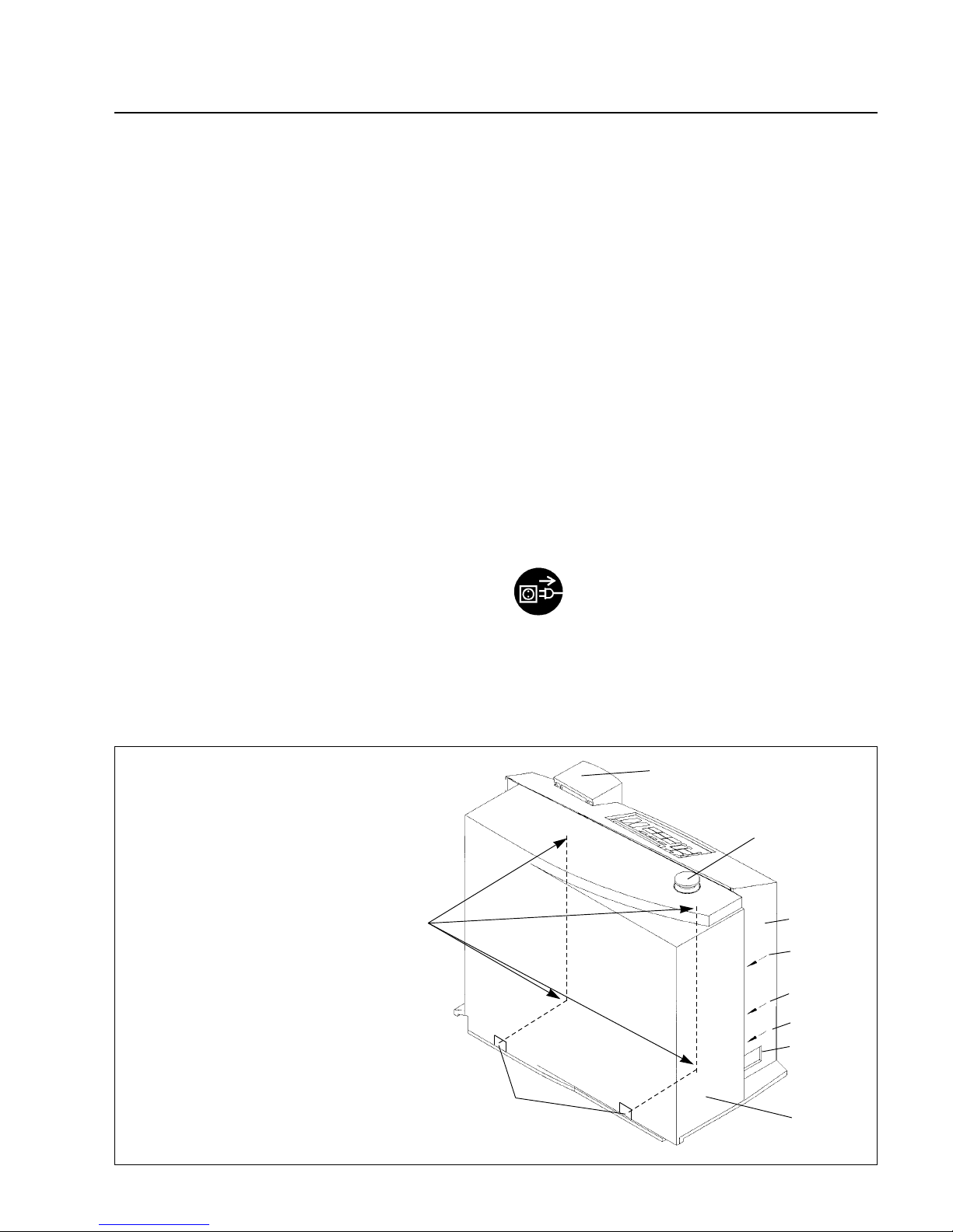
3 Maintenance
3.1 LEYBOLD Service
If equipment is returned to LEYBOLD, indicate whether
the equipment free of substances damaging to health or
whether it is contaminated.If it is contaminated also indicate the nature of the hazard. For this you must use a
form which has been prepared by us which we will provide upon request or you may copy the from which has
been reproduced on the next to the last page of this
handbook.
Please attach this form to the equipment or enclose it
with the equipment.
This „Declaration of Contamination“ is required to meet
German Law and to protect our personnel. Leybold must
return any equipment without a „Declaration of Contamination“ to the sender’s address.
Before shipping, fit the yellow screw-on seals on to the
connections EXHAUST (3/5) and GAS BALLAST (3/6)
(see Chapter 2.1.2).
3.2 Maintenance Plan
Maintenance work should be done on the UL 200 as
required. This work will normally be limited to exchanging
the oil in the D 2,5 E rotary vane pump and the built-in
air filters.
As a preventive measure it is recommended that you
check the rotary vane pump once a month. Here note
should be taken of the oil level and the colour of the oil.
For details on this please refer to the Operating Instructions GA 01.600 for the TRIVAC D 2,5 E which have
been enclosed.
Caution Only Arctic oil (Cat. No. 200 28 191)
must be used in the TRIVAC D 2,5 E in
the UL 200.
The monthly interval for the check is just a nominal period.If the leak detector is used heavily, in particular in the
sniffer mode, then this check should be performed more
frequently. The rotary vane pump is located on the side
of the mechanical section at the bottom of the leak
detector.
3.2.1 Opening the UL 200
Switch the UL 200 off.
Pull the mains cord on the UL 200.
Remove the cover (6/8) for the mechanical section.
Separate the UL 200 from other vacuum components at
the test port (6/2).
Turn the UL 200 so that it is orientated in the same way
as shown in Fig. 6.
31
TH 10.211/8.02 - 12/97
4
5
6
7
8
9
1
10
2
3
Key to Fig. 6
1 Hand unit
2 Test port
3 Cover for the electronics section
4 VENT input
5 Connection for the exhaust line
6 Gas ballast connection
7 Mains switch with mains fuses
8 Cover for the mechanical section
9 Openings for removal of the
cover for the mechanical section
10 Four screws for loosening the
cover for the electronics section
Fig. 6 View of the mechanical side
Page 32
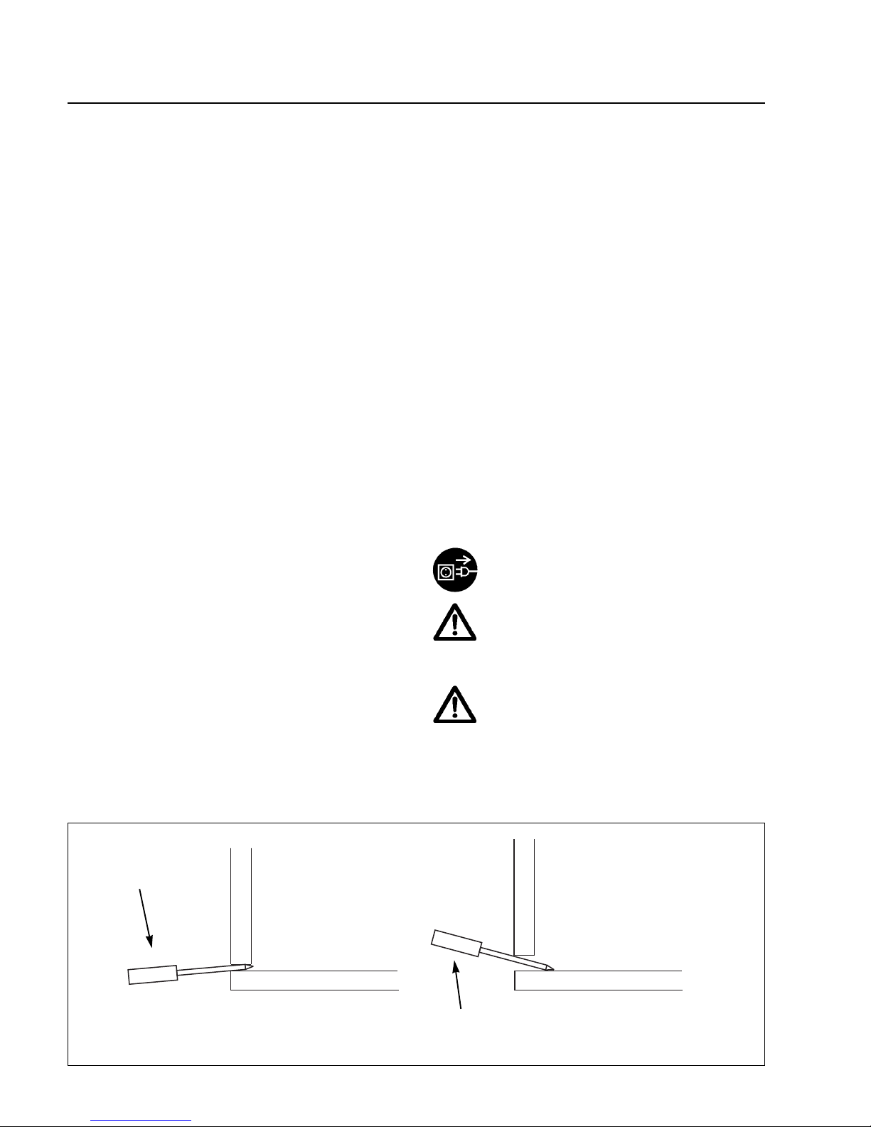
Use two flat blade screwdrivers and insert these into the
openings (6/9) and lever the cover for the mechanical
section out at the bottom.
In doing so, the cov er should at first be mo v ed somewhat
to the front by the downward motion of the screwdrivers
(7/1). Then cover may be lifted up by the upwards motion (7/2) of the screwdrivers so that the cover is disengaged completely.
Then pull the cover off the mechanical section up to its
stop and remove it to the front.
After completion of all maintenance work the cover of the
mechanical section (6/8) must engage properly in the
openings (6/9) at the bottom.
Removing the cover (6/3) for the electronics section.
Detach the hand unit (6/1). Pull the cable for the hand
unit out of its container on the UL 200.
Remove the cover for the mechanical section (6/8) as
described above.
Remove the four Phillips screws (6/10).
Pull the cover of the electronics section (6/7) back to the
rear and place it aside.
3.2.2 Exchanging the Filter Mats
The filter mats have been built-in to filter the dust out of
the air which is taken in. In order to ensure that the filter
mats will not throttle the air flow and so that sufficient
cooling is possible at all times, the filter mats should be
cleaned or exchanged as soon as these have attained a
dark grey colour.
Filter mats are used at three places within the UL 200.
a.) at the ventilation slit behind the attached hand unit
(only partly visible from the outside)
b.) on the face side to the back (only partly visible from
the outside)
c.) at the fan of the turbomolecular pump (not visible
from the outside).
To exchange the filter mats remove the covers (see
Chapter 3.2.1).
Filter mat a.) This filter mat is attached to the cover of
the electronics section by means of a
metal grid. Unscrew the grid and exchange the filter mat.
Filter mat b.) This filter mat is located on the side
together with a further metal grid in a
recess. It can be exchanged without
having to use any tools.
Filter mat c.) This filter mat is fixed in place by the f an of
the turbomolecular pump. Unscrew the
two screws which attach the fan and
exchange the filter mat.
Under certain circumstances a dirty mat ma y be cleaned
by shaking the dust out or by using a vacuum cleaner so
that the filter mat may be reused.
3.2.3 Exchanging the Oil
Remove the cover of the mechanical section (2/8) as
described in Chapter 3.2.1.
Warning Before starting with any disassembly
work on the pumps, pull the mains plug
first.When the pump has been pumping
hazardous substances, determined the
kind of hazard first and ensure that suitable safety precautions are taken.
Observe all safety regulations!
Caution When disposing of waste oil you must
observe the applicable regulations for
the safety of the environment!
The type of maintenance work and the maintenance
intervals as well as the oil change procedure are described in the corresponding Operating Instructions and
32
TH 10.211/8.02 - 12/97
Fig. 7 Disengaging the cover of the mechanical section
1
2
Page 33
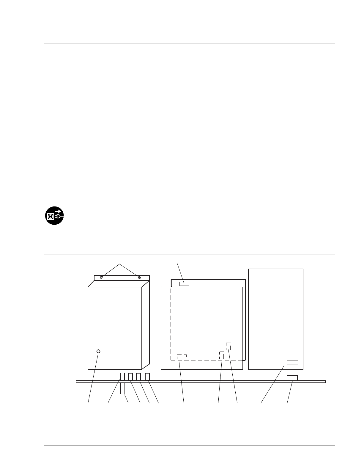
these must be followed closely.
As already stated in Chapter 3.2 only Arctic oil must be
used for the D 2,5 E pump in the UL 200.
Fit the cover for the mechanical section (6/8).
3.2.4 Cleaning
The housing of the UL 200 is made of painted plastic
parts. Thus for the purpose of cleaning, only such agents
should be used which are generally also used for other
pained or plastic surfaces (mild household cleaning
agents, for example). Normally a moistened piece of
cloth will do. Never use any solvents which are capable
of dissolving paint (like acetone, toluol, etc.).
A soft brush or a vacuum cleaner is recommended for
cleaning the ventilation slits.
3.2.5 Exchanging the Fuses
Warning Before exchanging the fuses you must
disconnect the mains cord.
Switch the UL 200 off.
Pull the mains cord on the UL 200.
Use a screwdriver to fold out the lid of the mains socket
(3/7) from the right (the mains switch is not affected by
this).
The fuses can be removed by pulling the drawers out
which are marked by the arrows.When reinserting these
make sure that the arrows point downwards.
In any case two fuses of the same rating must be inserted.The required mains fuses are:
- T 3.15 A slow-blow (20 x 5 mm dia.) for the 230 V
model.
- T 6.3 A slow-blow (20 x 5 mm dia.) for the 100 / 110 V
model.
After having exchanged the fuse(s) press the lid of the
mains socket firmly back on.
Insert the mains cord into the UL 200 and switch the
instrument on.
Besides these mains fuses several internal circuits are
fused separately. These fuses are listed in the following
table.See also Fig.8.
In order to exchange these fuses you must proceed as
follows:
- Switch the UL 200 off.
- Pull the mains cord on the UL 200.
- Remove the cover for the mechanical section (6/8) and
the cover for the electronics section (6/3) according to
Chapter 3.2.1.
33
TH 10.211/8.02 - 12/97
Fig. 8 Arrangement of the pr inted circuit boards and the fuses on the electronics side (top view)
TMP converter NT 12
MSV
STE board
I / O board
1 3 4 5 6 7 10
11
982
VD
Wiring back plane
12
13
Page 34

No in Desig- Fuse Remar k
Fig. nation rating
8
————————————————————————
1 F1 in 1 AT Protects the electronics which
NT 12 drive the turbomolecular pump.
Pull the electronics which drive
the turbomolecular pump out to
the top. For this loosen screws
(8/11).
Unscrew fuse F1.
2 F5 on 0.032AT Protects „TMP-Fail“ signal.
VD Pull the electronics which drive
the turbomolecular pump out to
the top. For this loosen screws
(8/11).
3 F6 6.3AT For protection of the forevacu-
um pump and the turbomolecular pump.
4 F4 0.032AT Protects „TMP Normal“ signal.
Pull the electronics which drive
the turbomolecular pump out to
the top. For this loosen screws
(8/11).
5 F2 0.032AT Protects „TMP Gate“ signal.
Pull the electronics which drive
the turbomolecular pump out to
the top. For this loosen screws
(8/11).
6 F3 0.032AT Protects „TMP Frequency“ sig-
nal.
Pull the electronics which drive
the turbomolecular pump out to
the top. For this loosen screws
(8/11).
7 F1 on 2AT 24 V system voltage of the
MSV mass spectrometer supply.
Loosen control panel (Fig. 4)
(two Phillips screws).
Loosen the panel which holds
the MSV board in place (two
Phillips screws).
Pull the MSV board (the board
at the back) up to the top. For
this insert a screwdriver into two
the recesses at the sides (top)
one after the other and lever the
MSV board out by resting the
screwdriver on the STE board.
No in Desig- Fuse Remark
Fig. nation rating
8
————————————————————————
8 F2 on 2AT 24 V system voltage of the
MSV mass spectrometer supply.
Loosen control panel (Fig. 4)
(two Phillips screws).
Loosen the panel which
holds the MSV board in
place (two Phillips screws).
Pull the MSV board up to the
top. For this insert a screwdriver into two the recesses
at the sides (top) one after
the other and lever the MSV
board out by resting the screwdriver on the STE board.
9 F1 on 0.8AT Protects the 24 V supply
I/O carr ied by the OPTION
board socket (3/13).
10 F1 on 0.8AT Supply voltage for the hand
MB unit.
11 -- -- -12 F3 on 1 AT For generating
MSV + 5 V and ± 15 V
13 F4 on 0.032 AMT Fuses for the anode
MSV and cathode voltages
As can be seen in Fig. 8,
Fuse 1 in the NT 12 frequency converter.
Fuses 2, 4, 5, 6 are located on the wiring backplane
under the NT 12 frequency converter.
Fuse 3 is located beneath the wiring backplane.
Fuses 7 and 8 are located on the MSV board.
Fuse 9 is located on the I/O board.
Fuse 10 is located on the wiring backplane under the I/O
board.
Finally re-install the covers for the electronics section
and the mechanical section in the reverse order.
34
TH 10.211/8.02 - 12/97
Page 35

4 Messages
During leak detection operations, the LCD display (3/2)
will indicate information which supports the operator
operating the UL 200. Besides measurement data also
current equipment conditions, operating hints as well as
warnings and error messages can be displayed.
4.1 Equipment Messages
All messages are listed in the following table in alphabetical order.
LCD text display Meaning
————————————————————————
Abort with <Clear> Function can be terminated
by pressing the „CLEAR“
push-button.
Are you sure ? <enter> Is this function to be continu-
ed? Continue by pressing the
ENTER push-button (4/8).
The function can be terminated with „CLEAR“.
Cal-Leak: x.xE-xxmbarl/s The value of the external cali-
brated leak can be entered.
Calibration finished The calibration process has
finished.
Calibration stopped The calibration process has
been stopped.
Close Cal-Leak <enter>, The external calibrated leak
should now be closed. Continue by pressing the ENTER
push-button (4/8).
Connect Testleak <enter> Connect the external calibra-
ted leak to the test port (3/2)
or the test sample, open calibrated leak.
Emission OFF ==> ON The emission of the mass
spectrometer (MS) is off and
will now be switched on.
The corresponding LED L4
(4/13) on the control panel
flashes.
Evacuation PE=x.xE-x The test sample connected to
the test port (3/2) is pumped
down. The inlet pressure is
displayed.
GROSS/FINE = x.xxx The GROSS/FINE conversion
factor is displayed.
Invalid Key Operation of this push-button
is not allowed in this mode.
Keyboard locked The keyboard has been
locked. If required, unlock
through menu item 14. The
ZERO function is accessed
via the OPTIONS socket (sniffer line, for example).
LCD text display Meaning
————————————————————————
LEYBOLD INFICON First message to appear after
the instrument has been switched on.
LR = x.xE-xx mbar·l/s Indication of the leak rate in
the unit mbar·l·s-1.
LR = x.xE-xx Pa m3/s Indication of the leak rate in
the unit Pa Pa m3/s.
LR=x.xE-xx PE=x.xE-x Simultaneous display of leak
rate and inlet pressure in the
unit which has been selected
(menu item 12).
No Cal in Menu Calibration can not be called
up as long as the menu is
open. First exit the menu by
operating the MENU pushbutton (4/7).
No Gasballast allowed The gas ballast valve can only
be opened in the Standby
mode. Operate STOP pushbutton (5/2).
No Int. Cal-Leak Internal calibration can not be
run. Either a calibrated leak
has not been built in or its
value has not been entered
(service menu item 81).
No Menu in Cal A calibration is running at the
moment. The menu can not
be selected. Terminate the
calibration process or cancel
it by pressing the CLEAR
push-button (4/10).
No Zero in CAL During calibration the ZERO
push-button is disabled. Terminate the calibration process
or cancel it by pressing the
CLEAR push-button (4/10).
No Zero in Standby The ZERO function can not
be run in the Standby mode.
No Zero in Vent The ZERO function can not
be run in the Vent mode.
Open Cal-Leak <enter> Open the externally fitted cali-
brated leak and continue the
calibration process by pressing the ENTER push-button
(4/8).
Password 1 changed The password has been suc-
cessfully changed.
Password 2 changed The password has been suc-
cessfully changed.
Password 1 locked The first password has not
been entered. Access to the
extended menu (menu lines
10 to 49) is restricted. The
default password is 0013.
Password 2 locked Access to the service menu
item has been restricted and
no changes can be made.
35
TH 10.211/8.02 - 12/97
Page 36

LCD text display Meaning
————————————————————————
The correct password must be
entered in service menu item
50 first.
Password failed The wrong password has
been entered. The default
password 1 is „0013“.
Password ok The password has been ente-
red correctly. The extended
menu (password 1) is now
accessible or changes can
now be made in the service
menu.
PE=x.xE-x PV=x.xE-x Display of inlet and forevacu-
um pressure in the previously
selected unit (menu item 12).
PE=xx.xxV PV=xx.xxV Display of sensor bridge volta-
ge for inlet and forevacuum
pressure.
In the vented state (V3 and
V2b open) a voltage of 8.67 V
must be displayed.In the case
of greater deviations
(± 100 mV) an alignment
should be run (see explanations for service menu item 92).
Perf orming Adjust Running of service menu item
92. Function can be terminated by operating the „CLEAR“
push-button (4/10).
Performing Autotune During the calibration pro-
cess, the anode voltage of the
detection system is changed
so that the correct mass position is used. Function can be
terminated by operating the
„CLEAR“ push-button (4/10).
Performing Bur n In Continuous test in the se-
quence START, STOP, VENT
(service menu item 91) is running.
Function can be terminated
by operating the „CLEAR“
push-button (4/10).
Performing CAL inter n A calibration is being run with
the internal calibrated leak.
Function can be terminated
by operating the „CLEAR“
push-button (4/10).
Performing Mass Scan A mass spectrum is output to
the RECORDER output.
Duration 70 s approx.
Function can be terminated
by operating the „CLEAR“
push-button (4/10).
Performing Offset Determination of the helium
background after the gas ballast valve has been closed.
LCD text display Meaning
————————————————————————
Performing Standby After having switched on the
automatic functions (serv.menu item 70), the UL 200 performs a warm boot and then
enters the Standby mode.
Performing Status
RS 232 A status log is output to the
SERIAL connection.
Performing Test Function of menu item 4 is
active.
Running Up TMP:xxxxHz The speed of the turbomole-
cular pump is indicated during
run-up.
Signal Stable ? <enter> The leak rate signal which is
indicated on the bargraph dis-
play (5/4) must be stable.
Then the calibration may be
continued by pressing the
ENTER push-button (4/8).
Sniff x.xE-xx mbar·l/s The instrument is running in
the sniffer mode (menu item
2) and the measured leak rate
is displayed.
Standby The Standby mode has been
attained.
Switch off Automatic This service menu item can
only be changed after having
switched off the automatic
function (service menu item
70).
Switch off Pump Both forevacuum pump and
turbomolecular pump must be
switched off when aligning the
Thermovac gauge. See des-
cription for service menu item
92.
Test failed Result of the mass test func-
tion of menu item 4.No helium
signal is measured. The heli-
um signal is lost in the signals
from mass 2 or mass 3.
Test ok Result of the mass test func-
tion of menu item 4.The mea-
surement signal is generated
by helium (mass 4).
UL 200 Version .... Display of instrument desi-
gnation and software version
number when switching the
instrument on.
Updating Parameter A parameter which remains
permanently stored in the
case of mains failures has
been changed and stored.
Vent Vent mode, test connection
(3/2) is vented. An optionally
connected venting valve (OP-
TION) is activated.
36
TH 10.211/8.02 - 12/97
Page 37

4.2 Warnings and Error Messages
The UL 200 is equipped with comprehensive self-diagnostic facilities.When a fault condition has been sensed
by the control board, this condition is indicated to the
operator via the LCD display (4/2) as far as possible.
Basically a difference is made between warnings and
error messages.
4.2.1 Warnings
Warnings are indicated
- when the measurement process has been interrupted
and when the UL 200 has been able to continue on its
own without user intervention (for e xample when cathode 1 is faulty the UL 200 automatically switches over to
cathode 2).
- when external influences impair the measurements (for
example an air inrush will cause the UL 200 to rev ert to
the Standby mode).
The UL 200 will indicate a massage on the display
(„W21: xxxxxxxxx“ ) and will remain in the Standby or the
measurement mode.
Warnings remain displayed until they are acknowledged
by pressing CLEAR or via a signal at the CONTROL
connection (see menu 14).Warnings are logged and can
be also be displayed at a later date through service
menu item 52.
4.2.2 Error Messages
Errors are events which force the UL 200 to interrupt its
measurement operations whereby the UL 200 is not able
to continue on it own.Errors are logged, and can be also
be displayed at a later date through service menu item
52.
The UL 200 remains in the error status described in the
following. After the fault cause has been removed the
error can be acknowledged by pressing the CLEAR
push-button (4/10) or via the CONTROL connection
(menu 14):The UL 200 then reverts to Standby.
Instrument status / instrument response in the case
of errors:
Hand unit Fig. 5:
All LEDs on the hand unit flash. As far as the error is
related to the hand unit the error code will also be displayed in the exponent display (5/9). START and
STOP push-buttons are disabled.
Control panel Fig. 4:
The trigger status displays (4/1), (4/3) and (4/4) are
off. The error information is indicated by the LCD display whereby an unambiguous error cause has been
assigned to each error condition (e.g. „E21: ...“).
In the case of several errors, the individual errors are
displayed cyclically for 2 s each.
Loudspeaker:
A frequency variable signal can be heard through the
loudspeaker. The frequency changes every 400 ms
from 500 to 1200 Hz so that this signal stands out
well from any ambient noises normally encountered,
and it can also be heard very well around the instrument.
RECORDER connection (3/11):
A voltage of 0 V is output through channels 1 and 2 of
the analogue outputs. This voltage is not attained
during normal operation.
CONTROL connection (3/12)
Function Contact Contact
closed open
————————————————————
Trigger 1 5, 7 5, 6
Trigger 2 8, 10 8, 9
Trigger 3 / Fail 11, 13 11, 12
Ready/Fail 14, 16 14, 15
Note
During a fault valve 2a is open. All other valves (except
the exhaust valve) are closed. Detection system and test
flange are separated. The emission is switched off
depending on the nature of the fault.
System errors are errors with occur in the control electronics and indicate the presence of a fault in the control
assembly or in the operation of the instrument. Due to
the nature of the fault, the information which can be provided is limited and incomplete.
The errors are mostly detected during initialization of the
UL 200. Logging is not possible.The instrument can not
be operated. Errors which are marked by a number between 10 ... 19 belong to this category of errors.
Note
Under extreme conditions (unknown software errors,
excessively high electromagnetic interference levels) the
built-in „watchdog“ circuit will prevent uncontrolled operation of the UL 200. This watchdog will cause the UL
200 to restart. After having done so, the instrument will
be running in the Standby mode. No error message will
be output.
Caution In case of enquiries please keep the
serial number and the software version
number of the instrument at hand (service menu item 51).
37
TH 10.211/8.02 - 12/97
Page 38

E13: (STE EEPROM failed)
- Acknowledgement signal ACK has not been received.
- Write/read test has failed during initialization.
EEPROM faulty.
E14: (STE Real-time Clock failed)
- Time and data information does not make any sense.
- Clock has stopped or control board is faulty.
E15: (STE Recorder failed)
Clock signal is not present; control board is faulty.
E16: (STE DUART failed)
No characters are output through the V24 interface.
Interface component on the control board is faulty.
E17: (STE A/D Converter failed)
The test measurement was not completed during initialization.
Control board is faulty.
E20: STE Ref U > -10.02 V
Limit at -10.02 V. The reference voltage is generated on
the control board.
Control board is faulty.
E21: STE Ref U < -10.44 V
Limit at -10.44 V.
The reference voltage is generated on the control board.
Control board is faulty.
W22: STE Battery U < 3 V
The battery voltage (Ubatt) on the control board has
dropped below 3 V.
The battery on the control board must be exchanged.
E 23: OPTION U24 > 30 V
U > 30 V at the options socket.
- A voltage which is too high has been applied to pin 1 of
the OPTION socket.
- 24 V power supply in the UL 200 has developed a fault.
E 24: OPTION U24 < 20 V
24 V at pin 1 of the OPTION socket is too low.
U < 20 V. Fuse on the I/O board has blown.
E 25: IO Valve U < 7 V
The voltage for the valves is dropped to under 8 V;
affects V1, for example.
I/O board is faulty.
E26: IO Valve > 10 V
When the voltage for the valves has dropped, the voltage is > 10 V; affects V1, for example.
I/O board is faulty.
E30: FB U24 < 20 V
Voltage for the hand unit is too low U < 20 V. P ossibly the
fuse (9/10) on the wiring backplane has blown.
E32: Amp T > 60 °C
Temperature of the preamplifier is too high T > 60 °C.
- Ambient temperature is too high.
- Air filters are dirty and must be exchanged.
TH 10.211/8.02 - 12/97
38
4.2.3 List of all Warnings and
Error Messages
Each message is composed of three parts:
The first letter of the message (E or W) indicates whether
this message is an error message or a warning message.This letter is followed by a two-digit number and then
the actual abbreviated message is displayed.
Listed in the following are all messages together with a
brief explanation as to what has caused this message
and what measures can be introduced.
Any abbreviations used in this list which ma y not be quite
so familiar are explained at the end of this list.
Hardware problems are covered by messages 01 to 61,
application-related problems by messages 71 to 81 and
software problems by messages 84 to 93.
Hardware Problems
Note
The first 17 error messages will possibly not be displayed in the way they are described. For this reason these
error messages are given in brackets.
E01: (FB-RAM)
RAM test for the hand unit (Fig.5) has failed;
exchange the hand unit (Fig. 5).
E02: (FB-ROM)
ROM test for the hand unit (Fig.5) has failed;
exchange the hand unit (Fig. 5).
E03: (FB-No Communication) during self test only
No communication during the self test.
Hand unit (Fig. 5) or interface component is faulty.
E04: (FB-Watch-Dog)
Watchdog in the hand unit has sensed something wrong.
Hand unit is faulty.
E05: (FB-Communication)
There is no communication. The hand unit is not receiving any data from the control board.
Interface component on the control board is faulty.
Interface component in the hand unit (Fig.5) is faulty.
E10: (GB-Failed)
Busy flag on the control panel has not been reset.
Exchange control panel (Fig. 4).
E11: (STE RAM failed)
Write/read test has failed during initialization.
Control board faulty.
E12: (STE ROM failed)
An incorrect checksum has been determined.
Control board faulty.
Page 39

W33: Amp T < 10 °C
- The temperature sensor in the preamplifier signals
T < 10 °C.
Run-up time for the forevacuum pump will be longer.
- Temperature sensor faulty.
E34: MSV U24 > 18.3 V
Signal MVPZN on the MSV board is active;
24 V signal voltage is too low U < 18.3 V.
- Fuse F1 on the MSV board has blown.
- 24 V power supply voltage is missing.
!!! Switch the UL 200 off!!
The missing voltage will cause the exhaust v alv e on the
rotary vane pump to close which in turn can lead to a
contamination of the vacuum system.Clean the UL 200
as required and check the oil level.
- Reference voltage UREF on the MSV board XT7/1 is
too high > 5 V.
E35: MSV Anod-Cat-U > 130 V
Anode-Cathode voltage is too high, U > 130 V.
MSV is faulty.
E36: MSV Anod-Cat-U < 30 V
Anode-Cathode voltage is too low, U < 30 V.
MSV is faulty.
E37: MSV Sup-Nom U>>
Signal MFSZH on MSV board is active.
Suppressor signal command variable is too high.
- Suppressor voltage has a short circuit.
MSV is faulty.
E38: MSV Sup-Pot > 363 V
U > 363 V
MSV is faulty.
E39: MSV Sup-Pot < 297 V
U < 297 V
MSV is faulty.
E40: MSV Anod-Pot U>>
The actual anode potential exceeds its nominal value by
10 %.
The nominal value can be displayed in the ser vice menu
(line 55).
MSV is faulty.
E41: MSV Anod-Pot U<<
The actual anode potential has dropped below its nominal value by over 10%. The nominal value can be displayed in the service menu (line 55).
MSV is faulty.
E42: MSV Anod-Nom U>>
Signal MFAZH on MSV board is active.
- Anode voltage has been short-circuited.
- Nominal value of the anode voltage is too high.Anode
voltage is limited to about 1,200 V.
E43: MSV Cat-Heater I>>
Signal MPKZH on MSV board is active; cathode current
is too high;
I > 3.6 A
MSV is faulty.
E44: MSV Cat-Heater I<<
Signal MPKZN on MSV board is active; cathode current
is too low;
I < 0.2 A
MSV is faulty.
W45: MSV Cathode 1 defect
Signal MSIBE on MSV board is not active.
Emission for cathode 1 can not be switched on.
UL 200 switches to cathode 2.
Warning is repeated when switching on the UL 200 the
next time. The warning will cease to appear when switching on the emission for cathode 1 manually through
the service menu.
Order a new ion source.
W46: MSV Cathode 2 defect
Signal MSIBE on MSV board is not active.
Emission for cathode 2 can not be switched on.
UL 200 switches to cathode 1.
Warning is repeated when switching on the UL 200 the
next time.
The warning will cease to appear when switching on the
emission for cathode 2 manually through the service
menu.
Order a new ion source.
E47: MSV Cathodes defect
Signal MSIBE on MSV board is not active.
Emission can not be switched on.
- Exchange the cathodes by exchanging the ion source.
After having exchanged the ion source it must be possible to switch on both cathodes manually via the service menu.
E48: MSV Fuse F2 defect
Signal MSAFD on MSV board is active; anode heater
fuse has blown.
Replace fuse F2 on the MSV board.
E49:TMP-Fail
Signal on the NT 12 is active.
Turbomolecular pump has failed.
Priority: 1
- Fuse (1 A) in the NT 12 has blown.
- Turbomolecular pump is faulty.
E50:TMP No Clock
Clock from the frequency converter has failed.
Priority: 2
- NT 12 is faulty.
E51:TMP-Freq F>1100 Hz
TMP frequency is too high f = 1100 Hz
Priority: 3
- NT 12 is faulty.
39
TH 10.211/8.02 - 12/97
Page 40

E52:TMP-Freq F<<,t>5min
TMP frequency is too low.
The frequency of f = 1000 Hz has not been reached after
t = 5 minutes.Time t star ts as soon as the pressure has
dropped below the PV threshold pressure of
PV = 1 mbar;
Priority: 3
- NT 12 is faulty.
- Turbomolecular pump is faulty.
E53:TMP-FREQ<<
TMP frequency too low.
- Signal TMP-Normal is no longer active
- Fuse F4 has blown
- NT 12 faulty
- Turbomolecular pump faulty
E54: Electr.T>60 °C
The temperature on the electronics side is too high
T > 60 °C.
- Ambient temperature is too high.
- Internal ventilation has failed.
- Air filters are dirty and must be exchanged.
W55: Electr.T<10°C
- The temperature sensor on the wiring plane indicates
T < 10 °C.
The forevacuum pump will take longer to run up.
- The temperature sensor is faulty.
E56: PE defect U<270mV
U < 0.27 V; filament broken.
Exchange the sensing cell on the Thermovac which
measures PE.
E57: PE U>9.5V
The bridge voltage PE > 9.5 V for over 500 ms; see service menu item 92.
Realign on I/O board, or exchange the sensing cell on
the Thermovac gauge (short circuited or low resistance
filament).
This error message is not checked during the pumpdown process and during „Vent“.
E58: PV defect U<270mV
U < 0.27 V; filament broken.
Exchange the sensing cell on the Thermovac which
measures PV.
E59: PV U>9.5V
The bridge voltage PV > 9.5 V for over 500 ms; see service menu item 92.
Realign on I/O board, or exchange the sensing cell on
the Thermovac gauge (short circuited or low resistance
filament).
This error message is not checked during the pumpdown process and during „Vent“.
W60: PV> 1mbar,t=5min
Pv > 1 mbar after t = 5 minutes since switching on.
Run up time for the forevacuum pump is too long.
E61: Emission Fail
Emission should be switched on.MSV subassembly indicates a fault.
MENB emission current not within range.
E62: Capillary blocked
In the sniffer mode the intake pressure of the sniffer line
is controlled.If the pressure falls below 0.1 mbar, the flow
through the capillary is too low (contamination) or the
capillary is blocked (foreign objects, par ticles).
E63: Capillary broken
In the sniffer mode the intake pressure of the sniffer line
is controlled. If the pressure exceeds 0.3 mbar, the flow
through the capillary is too big (no leak tightness, broken
capillary)
Application-Related Problems
W71: No Part. Flow Valve
No return signal from the partial flow valve after it has
been activated.
24 V missing at OPTION pin 6.
Partial flow valve has not been properly connected or it
is faulty.
W72: Emission Off PE>>
PE >> 0.2 or 3 mbar.
Due to an air inrush, for example.
The UL 200 will again try to resume the measurement
mode.
W73: Emission Off PV>>
PV >> 0.2 or 3 mbar
Due to an air inrush, for example.
The UL 200 will again try to resume the measurement
mode.
W75: EVAC stopped Time 1
See explanations for menu item 10.
- Check the application.
- Optimize Time 1.
W76: EVAC stopped Time 2
See explanations for menu item 10.
- Check the application.
- Optimize Time 2.
E77: Peak not in Range
The signal maximum has shifted to the mass range alignment limits.
- Check the basic setting for the anode voltage through
the service menu.
- Check calibrated leak.
W78: Difference too small
The amplifier voltage difference between opened and
closed calibrated leak is less than 10 mV.
Calibrated leak has not been closed properly.
40
TH 10.211/8.02 - 12/97
Page 41

W79: Signal too small
Calibrated leak is too small or has not been opened.
Preamplifier voltage < 10 mV.
The tune process is ignored and the calibration process
is continued.
W80: Request for Cal
Request for calibration.
See explanations for menu item 24.
Since the last request for calibration, the temperature
has changed by 5 °C or the UL 200 has warmed up for
30 minutes.
W81: Factor out of Range
The calculated factor falls out of the valid range.The old
factor which has been calculated is retained.
Possible fault cause:
- The conditions for calibration have not been maintained.
- The leak rate of the calibrated leak which was entered
is much too high or much too small.
Software Problems
W84: EEPROM Write XX
The parameter could not be written into the EEPROM.
XX indicates the number of the parameter.
E85: Parameter Lost XX
At least one parameter has been lost.
The UL 200 will assume the default value for that parameter.
Check trigger values and calibrate the instrument. XX
indicates the number of the parameter.
W86: FB Timeout
No data have been received from the hand unit for 500
ms.
This error occurs as a follow-up error to error numbers
1 ... 5.
The hand unit has not been connected.
E87: FB CRC-Error
The data from the hand unit have not been received correctly over a period of 500 ms.
- Faulty data link.
W88: Serial Parity
See interface description SB 10.211.
W89: Serial Framing
See interface description SB 10.211.
W90: Serial Overrun
See interface description SB 10.211.
W91: Serial B. Overrun
See interface description SB 10.211.
W92: Serial Missing EOS
See interface description SB 10.211.
W93: Syntax Error
See interface description SB 10.211.
Abbreviations which are used:
FB Hand unit
MSV Mass spectrometer supply (the rear board of the
two electronics boards)
STE Control board = CPU board (the front board of the
two electronics boards)
TMP Turbomolecular pump
41
TH 10.211/8.02 - 12/97
Page 42

5 Definition of Terms
Autoranging The range of the preamplifier and
the vacuum ranges are selected
automatically.
The autoranging feature of the
UL 200 covers the entire range or
leak rates depending on the selected operating mode: „2: Mode
Vacuum“, „2: Mode Sniff N/QT“ or
„2:Mode Partial normal/oil-free“.
Not only the leak rate signal, but
also the pressure in the test sample (inlet pressure PE) and the
forevacuum pressure (PV) are
used for control purposes.Range
switching between the main ranges is performed via valves. Fine
range switching within the main
ranges is implemented by switching over the gain factor of the
preamplifier.
Autotune,
mass alignment This function automatically aligns
the mass spectrometer so that a
maximum leak rate is displayed.
The control computer changes
the voltage which accelerates the
ions in the selected mass range
until a maximum ion current is
detected by the ion detector.
During each calibration the mass
alignment is run automatically.
Autozero Determination and compensation
of the helium background.
With this function, the internal
Zero level of the leak rate signal
is determined in order to avoid a
readout of the internal helium
background and mistaking it as a
proper measured value.
This function is run automatically
each time when pressing STOP
to enter Standby or Vent, or when
entering the CAL mode.The Zero
measurement is only run in the
most sensitive preamplifier range
and it is calculated for the other
ranges. The Zero values which
have been determined in this way
for the various measurement ranges are stored and are used to
correct all leak rates which are
determined later on.
If subsequently negative leak rates are obtained due to this correction, the stored offset values
are changed so that Zero will be
the lowest value which can be
obtained. In this way the values
adapt automatically to a decaying
background (adaptive background correction).
The entire measurement process
may take up to 10 s after operating STOP. However, this process
is interrupted automatically when
operating the START push-button
in the mean time.
Basic menu Comprises menu lines 1 to 9.
This part of the menu is not protected by a password.For details
please refer to Chapter 2.5 and
2.5.4 (menu line 14).
CONTROL Control connection on the rear of
the instrument.
Default condition Status of the UL 200 when sup-
plied by the factory.
Extended menu Comprises menu lines 10 to 49.
Access to this part of the menu
can be restricted / or enabled by
entering the first password (see
also Chapter 2.5).
FINE Valves V2a and V4 are open;
PE < 0.2 mbar; the turbomolecular pump with its high pumping
speed is connected to the inlet
flange.
GROSS Valves V2a and V2b are open;PE
= 0.2 ... 3 mbar.
Internal helium
background The existing helium partial pres-
sure in the measurement system.
The level of the internal helium
background is measured in the
Standby mode and subtracted
from the measured signal.
Measure,
measurement mode The UL 200 measures the leak
rate of the test sample.
Menu item Menu lines numbered from
1 ... 99.
Standby Mode which is attained by opera-
ting the STOP push-button; the
START LED on the hand unit is
turned off. The LCD display (3/2)
indicates the message Standby.
All valves leading to the test
connection are closed. The measurement system is internally disconnected from the test connection.
42
TH 10.211/8.02 - 12/97
Page 43

Service menu Compr ises menu lines 50 to 99.
The service menu is called up by
operating the Service push-button (see also Chapter 2.5 and
2.5.4).
Partial flow range 1 Valves V2a, V4.1 and V8 are
open; PE = 1 ... 100 mbar.
Partial flow range 2 Valves V2a, V2b and V8 are
open; PE = 0.1 ... 2 mbar ; equivalent to the GROSS state plus
additional external partial flow
pump.
Partial flow range 3 Valves V2a, V4 and V8 are open;
PE = 0.01 ...0.1 mbar;equiv alent
to the FINE state plus additional
external partial flow pump.
43
TH 10.211/8.02 - 12/97
Page 44

44
TH 10.211/8.02 - 12/97
Page 45
TH 10.211/8.02 - 12/97
45
S A M P L E
Declaration of Contamination of Vacuum Equipment and Components
The repair and/or service of vacuum equipment and components will only be carried out if a correctly completed declaration has
been submitted. Non-completion will result in delay. The manufacturer could refuse to accept any equipment without a declaration.
This declaration can only be completed and signed by authorized and qualified staff.
1. Description of Vacuum Equipment and Components
- Equipment type/model: _________________________________
- Code No.: _________________________________
- Serial No.: _________________________________
- Invoice No.: _________________________________
- Delivery date:
__________________________
2. Reason for Return
____________________________________________
____________________________________________
____________________________________________
____________________________________________
____________________________________________
____________________________________________
3. Condition of the Vacuum Equipment and Components
- Has the equipment been used?
yes
❒ no ❒
- What type of pump oil/liquid was used? _________
- Is the equipment free from potentially
harmful substances?
yes ❒ (go to Section 5)
no ❒ (go to Section 4)
4. Process related Contamination of Vacuum
Equipment and Components:
- toxic yes ❒ no ❒
- corrosive yes ❒ no ❒
- explosive*) yes ❒ no ❒
- biological hazard*) yes ❒ no ❒
- radioactive*) yes ❒ no ❒
- other har mful substances yes ❒ no ❒
*) Vacuum equipment and components which ha v e been contaminated b y biological e xplosiv e or radioactiv e substances , will
not accepted without written evidence of decontamination!
Please list all substances, gases and by-products which may have come into contact with the equipment:
Trade name
Product name Chemical name Dangerous Measures First aid in case of
Manufacturer (or Symbol) material class if spillage human contact
1.
2.
3.
4.
5.
Copies: Page 1 (white) to manufacturer or representative - Page 2 (yellow) attach to consignment packaging securety - Page 3 (blue) copy for file of sender
5. Legally Binding Declaration
I hereby declare that the information supplied on this form is complete and accurate.The despatch of the contaminated
vacuum equipment and components will be in accordance with the appropriate regulations covering Packaging, Transportation and Labelling of Dangerous Substances.
Name of organisation or company:_____________________________________________________________________
Address: _____________________________ Post code:______________________________________
Tel.: ______________________________________________________________________________
Fax: _____________________________ Telex: _________________________________________
Name: ______________________________________________________________________________
Job title: ______________________________________________________________________________
Date: _____________________________ Company stamp:
Legally binding signature:____________________________________________________________________________
Copyright © 1991 by MaschinenbauVerlag GmbH, Lyoner Straße 18, 6000 Frankfurt/M. 71 Order No.: 2121
Page 46

TH 10.211/8.02 - 12/97
1.80.7.676.74 RSP 12.97
Printed in Germany on chlorine-free bleached paper
LEYBOLD INFICON
Bonner Strasse 498 (Bayenthal)
D-50968 Cologne
Tel.: + 49 (221) 347-0
Fax: + 49 (221) 347-1250
http://www.leyboldvac.de
e-mail:[email protected]
 Loading...