

Page 1
AF 1,6/4-8/16-25/40-65
AK 1,6/4-8/16-25/40-65
Auspuff-Filter
Abscheider
Exhaust Filters
Condensate Traps
Kat.-Nr./Cat. No.
189 02/06/11/16
188 02/06/11/16
GA 01.299/7
Operating Instructions
Gebrauchsanleitung
Vakuum-Lösungen
ApplikationsUnterstützung
Service
LEYBOLD VAKUUM
AF 1,6/4-8/16-25/40-65
AK 1,6/4-8/16-25/40-65
Auspuff-Filter
Abscheider
Exhaust Filters
Condensate Traps
Kat.-Nr./Cat. No.
189 02/06/11/16
188 02/06/11/16
GA 01.299/7
Operating Instructions
Gebrauchsanleitung
Vakuum-Lösungen
ApplikationsUnterstützung
Service
LEYBOLD VAKUUM
Page 2
Inhalt
. . . . . . . . . . . . . . . . . . . . . . . . . . . . . . . .Seite
1 Beschreibung . . . . . . . . . . . . . . . . . . . . . . . .3
1.1 Aufbau und Funktion . . . . . . . . . . . . . . . . . . .3
1.2 Technische Daten . . . . . . . . . . . . . . . . . . . . . .4
2 Montage . . . . . . . . . . . . . . . . . . . . . . . . . . . .7
2.1 Montage AK 1,6 und AF 1,6 . . . . . . . . . . . . . .7
2.2 Montage AK/AF 4-8, 16-25 und 50-65 . . . . . . .7
3 Wartung . . . . . . . . . . . . . . . . . . . . . . . . . . .10
3.1 Auspuff-Filter . . . . . . . . . . . . . . . . . . . . . . . .10
3.2 Abscheider . . . . . . . . . . . . . . . . . . . . . . . . . .11
3.3 Service bei Leybold . . . . . . . . . . . . . . . . . . .12
The English Operating Instructions
start on page 14
Abbildungen
Abbildungs-Hinweise, z.B. (1/2), geben mit der ersten
Ziffer die Abbildungsnummer und mit der zweiten Ziffer
die Position in dieser Abbildung an.
Leybold-Service
Falls Sie ein Gerät an Leybold schicken, geben Sie an,
ob das Gerät frei von gesundheitsgefährdenden Schadstoffen ist oder ob es kontaminiert ist.
Wenn es kontaminiert ist, geben Sie auch die Art der
Gefährdung an. Geräte ohne Erklärung über Kontaminierung muß Leybold an den Absender zurückschicken.
Steht bei Arbeits- und Betriebsverfahren,
die genau einzuhalten sind, um eine
Gefährdung von Personen zu vermeiden.
Bezieht sich auf Arbeits- und Betriebsverfahren, die genau einzuhalten sind, um
Beschädigungen oder Zerstörungen der
Geräte zu vermeiden.
Eine Änderung der Konstruktion und der angegebenen
Daten behalten wir uns vor. Die Abbildungen sind unverbindlich.
2
GA 01.299/7 - 03/99
Vorsicht
Achtung
Inhalt
. . . . . . . . . . . . . . . . . . . . . . . . . . . . . . . .Seite
1 Beschreibung . . . . . . . . . . . . . . . . . . . . . . . .3
1.1 Aufbau und Funktion . . . . . . . . . . . . . . . . . . .3
1.2 Technische Daten . . . . . . . . . . . . . . . . . . . . . .4
2 Montage . . . . . . . . . . . . . . . . . . . . . . . . . . . .7
2.1 Montage AK 1,6 und AF 1,6 . . . . . . . . . . . . . .7
2.2 Montage AK/AF 4-8, 16-25 und 50-65 . . . . . . .7
3 Wartung . . . . . . . . . . . . . . . . . . . . . . . . . . .10
3.1 Auspuff-Filter . . . . . . . . . . . . . . . . . . . . . . . .10
3.2 Abscheider . . . . . . . . . . . . . . . . . . . . . . . . . .11
3.3 Service bei Leybold . . . . . . . . . . . . . . . . . . .12
The English Operating Instructions
start on page 14
Abbildungen
Abbildungs-Hinweise, z.B. (1/2), geben mit der ersten
Ziffer die Abbildungsnummer und mit der zweiten Ziffer
die Position in dieser Abbildung an.
Leybold-Service
Falls Sie ein Gerät an Leybold schicken, geben Sie an,
ob das Gerät frei von gesundheitsgefährdenden Schadstoffen ist oder ob es kontaminiert ist.
Wenn es kontaminiert ist, geben Sie auch die Art der
Gefährdung an. Geräte ohne Erklärung über Kontaminierung muß Leybold an den Absender zurückschicken.
Steht bei Arbeits- und Betriebsverfahren,
die genau einzuhalten sind, um eine
Gefährdung von Personen zu vermeiden.
Bezieht sich auf Arbeits- und Betriebsverfahren, die genau einzuhalten sind, um
Beschädigungen oder Zerstörungen der
Geräte zu vermeiden.
Eine Änderung der Konstruktion und der angegebenen
Daten behalten wir uns vor. Die Abbildungen sind unverbindlich.
2
GA 01.299/7 - 03/99
Vorsicht
Achtung
Page 3
1 Beschreibung
1.1 Aufbau und Funktion
Auspuff-Filter
Im Auspuff-Filter werden die Ölnebel und Aerosole festgehalten, leichtflüchtige Stoffe und Aromastoffe passieren das Filter.
Das Filterelement wird von dem ausgeförderten Gas der
V akuumpumpe durchströmt, wobei die darin enthaltenen
kleinsten Öltropfen und Schmutzpartikel im Filterelement
zurückgehalten werden. Die ausgeschiedenen Öltropfen
sammeln sich im Auspuff-Filter.
Im Auspuff-Filter AF 40-65 sind zwei Filterelemente
parallel geschaltet.
Schmutz und Crackprodukte des Öls können die Filterelemente im Lauf des Betriebes zusetzen, wodurch in
der Pumpe ein Überdruck entstehen kann.
Damit der Überdruck den zulässigen Wert (ca. 1,5 bar)
nicht übersteigt, ist im Auspuff-Filter ein ÜberdruckVentil eingebaut.
Sollte das Filter verstopft sein, öffnet das eingebaute
Überdruck-Ventil, so daß die von der Pumpe ausgestoßenen Ölnebel direkt ins Freie gelangen.
Mögliche Schäden durch sich aufbauenden Überdruck
werden somit verhindert.
Eine den Sicherheitsvorschriften entsprechende Auspuff-Leitung ist unerläßlich,
wenn giftige Gase oder Dämpfe abgesaugt
werden.
Beachten Sie für die gepumpten Medien die
entsprechenden Sicherheitsvorschriften.
Abscheider
In die Ansaugleitung eingebaute Abscheider schützen
die Pumpe vor Kondensation, die beim Abpumpen aus
den angesaugten Dämpfen oder Gasen anfallen können.
In die Auspuf fleitung eingebaut, schützen Abscheider vor
dem Rückfluß von Flüssigkeiten, die in der Auspuffleitung kondensieren können.
Abscheider können wahlweise an der Saug- und/oder
Druckseite einer TRIVAC-Pumpe angebaut werden.
3
GA 01.299/7 - 03/99
Vorsicht
1 Beschreibung
1.1 Aufbau und Funktion
Auspuff-Filter
Im Auspuff-Filter werden die Ölnebel und Aerosole festgehalten, leichtflüchtige Stoffe und Aromastoffe passieren das Filter.
Das Filterelement wird von dem ausgeförderten Gas der
V akuumpumpe durchströmt, wobei die darin enthaltenen
kleinsten Öltropfen und Schmutzpartikel im Filterelement
zurückgehalten werden. Die ausgeschiedenen Öltropfen
sammeln sich im Auspuff-Filter.
Im Auspuff-Filter AF 40-65 sind zwei Filterelemente
parallel geschaltet.
Schmutz und Crackprodukte des Öls können die Filterelemente im Lauf des Betriebes zusetzen, wodurch in
der Pumpe ein Überdruck entstehen kann.
Damit der Überdruck den zulässigen Wert (ca. 1,5 bar)
nicht übersteigt, ist im Auspuff-Filter ein ÜberdruckVentil eingebaut.
Sollte das Filter verstopft sein, öffnet das eingebaute
Überdruck-Ventil, so daß die von der Pumpe ausgestoßenen Ölnebel direkt ins Freie gelangen.
Mögliche Schäden durch sich aufbauenden Überdruck
werden somit verhindert.
Eine den Sicherheitsvorschriften entsprechende Auspuff-Leitung ist unerläßlich,
wenn giftige Gase oder Dämpfe abgesaugt
werden.
Beachten Sie für die gepumpten Medien die
entsprechenden Sicherheitsvorschriften.
Abscheider
In die Ansaugleitung eingebaute Abscheider schützen
die Pumpe vor Kondensation, die beim Abpumpen aus
den angesaugten Dämpfen oder Gasen anfallen können.
In die Auspuf fleitung eingebaut, schützen Abscheider vor
dem Rückfluß von Flüssigkeiten, die in der Auspuffleitung kondensieren können.
Abscheider können wahlweise an der Saug- und/oder
Druckseite einer TRIVAC-Pumpe angebaut werden.
3
GA 01.299/7 - 03/99
Vorsicht
Page 4
GA 01.299/7 - 03/99
1.2 Technische Daten
Auspuff-Filter AF 1,5 AF 4-8 AF 16-25 AF 40-65
Verwendung für Pumpe S/D 1,6 B S/D 4 B S/D 16 B/BCS S/D 40 B/BCS
S/D 8 B S/D 25 B/BCS S/D 65 B/BCS
Anschlußflansche DN 16 KF DN 16 KF DN 25 KF DN 40 KF
Max. Fassungsvermögen 0,1 l 0,37 l 0,48 l 1,0 l
Gewicht 0,9 kg 2,4 kg 2,4 kg 6,5 kg
Auspuff-Filter, Kat.-Nr. 189 02 189 06 189 11 189 16
Ersatz-Filterelement, Kat.-Nr. 189 70 189 71 189 72 189 73 (2x)
Abscheider AK 1,5 AK 4-8 AK 16-25 AK 40-65
Verwendung für Pumpe S/D 1,6 B S/D 4 B S/D 16 B/BCS S/D 40 B/BCS
S/D 8 B S/D 25 B/BCS S/D 65 B/BCS
Anschlußflansche DN 16 KF DN 16 KF DN 25 KF DN 40 KF
Max. Fassungsvermögen 0,16 l 0,66 l 1,2 l 3,0 l
Gewicht 0,7 kg 1,7 kg 2,4 kg 5,5 kg
Abscheider, Kat.-Nr. 188 02 188 06 188 11 188 16
Zubehör
Ablaßhahn 188 90 188 90 188 90 188 90
Ablaßhahn, vakuumdicht 188 91 188 91 188 91 188 91
Zentrierring 183 26 183 26 183 27 183 28
Spannring 183 41 183 41 183 42 183 43
4
GA 01.299/7 - 03/99
1.2 Technische Daten
Auspuff-Filter AF 1,5 AF 4-8 AF 16-25 AF 40-65
Verwendung für Pumpe S/D 1,6 B S/D 4 B S/D 16 B/BCS S/D 40 B/BCS
S/D 8 B S/D 25 B/BCS S/D 65 B/BCS
Anschlußflansche DN 16 KF DN 16 KF DN 25 KF DN 40 KF
Max. Fassungsvermögen 0,1 l 0,37 l 0,48 l 1,0 l
Gewicht 0,9 kg 2,4 kg 2,4 kg 6,5 kg
Auspuff-Filter, Kat.-Nr. 189 02 189 06 189 11 189 16
Ersatz-Filterelement, Kat.-Nr. 189 70 189 71 189 72 189 73 (2x)
Abscheider AK 1,5 AK 4-8 AK 16-25 AK 40-65
Verwendung für Pumpe S/D 1,6 B S/D 4 B S/D 16 B/BCS S/D 40 B/BCS
S/D 8 B S/D 25 B/BCS S/D 65 B/BCS
Anschlußflansche DN 16 KF DN 16 KF DN 25 KF DN 40 KF
Max. Fassungsvermögen 0,16 l 0,66 l 1,2 l 3,0 l
Gewicht 0,7 kg 1,7 kg 2,4 kg 5,5 kg
Abscheider, Kat.-Nr. 188 02 188 06 188 11 188 16
Zubehör
Ablaßhahn 188 90 188 90 188 90 188 90
Ablaßhahn, vakuumdicht 188 91 188 91 188 91 188 91
Zentrierring 183 26 183 26 183 27 183 28
Spannring 183 41 183 41 183 42 183 43
4
Page 5
GA 01.299/7 - 03/99
5
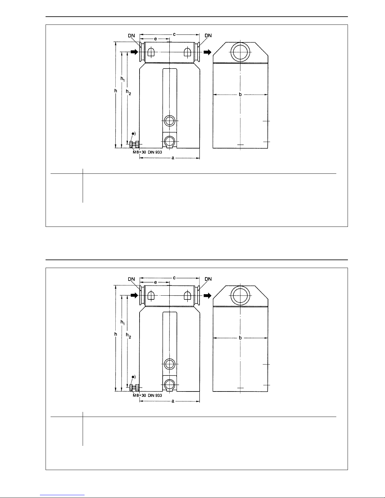
Abb. 1 Maßzeichnung der Auspuff-Filter, Abscheider ähnlich, Maße in mm (inch)
DN a b c e h h1 h2
AF/AK 1,6 16 KF 73 (2
7
/8) 72 (43) 76 (3) 25 (1) 164 (6 15/32) 149 (5 7/8)-
AF/AK 4-8 16 KF 90 (3
9
/16) 90 (3 9/16) 120 (4 3/4) 60 (2 3/8) 194 (7 21/32) 178 (7) -
AF/AK 16-25 25 KF 110 (4
11
/32) 125 (4 15/16) 142 (5 19/32) 71 (2 13/16) 214 (8 7/16) 193 (7 19/32)-
AF/AK 40-65* 40 KF 140 (5
17
/32) 156 (6 5/32) 170 (6 23/32) 85 (3 11/32) 300 (11 13/16) 271 (10 11/16) 261 (10 9/32)
GA 01.299/7 - 03/99
5
Abb. 1 Maßzeichnung der Auspuff-Filter, Abscheider ähnlich, Maße in mm (inch)
DN a b c e h h1 h2
AF/AK 1,6 16 KF 73 (2
7
/8) 72 (43) 76 (3) 25 (1) 164 (6 15/32) 149 (5 7/8)-
AF/AK 4-8 16 KF 90 (3
9
/16) 90 (3 9/16) 120 (4 3/4) 60 (2 3/8) 194 (7 21/32) 178 (7) -
AF/AK 16-25 25 KF 110 (4
11
/32) 125 (4 15/16) 142 (5 19/32) 71 (2 13/16) 214 (8 7/16) 193 (7 19/32)-
AF/AK 40-65* 40 KF 140 (5
17
/32) 156 (6 5/32) 170 (6 23/32) 85 (3 11/32) 300 (11 13/16) 271 (10 11/16) 261 (10 9/32)
Page 6
GA 01.299/7 - 03/99
6
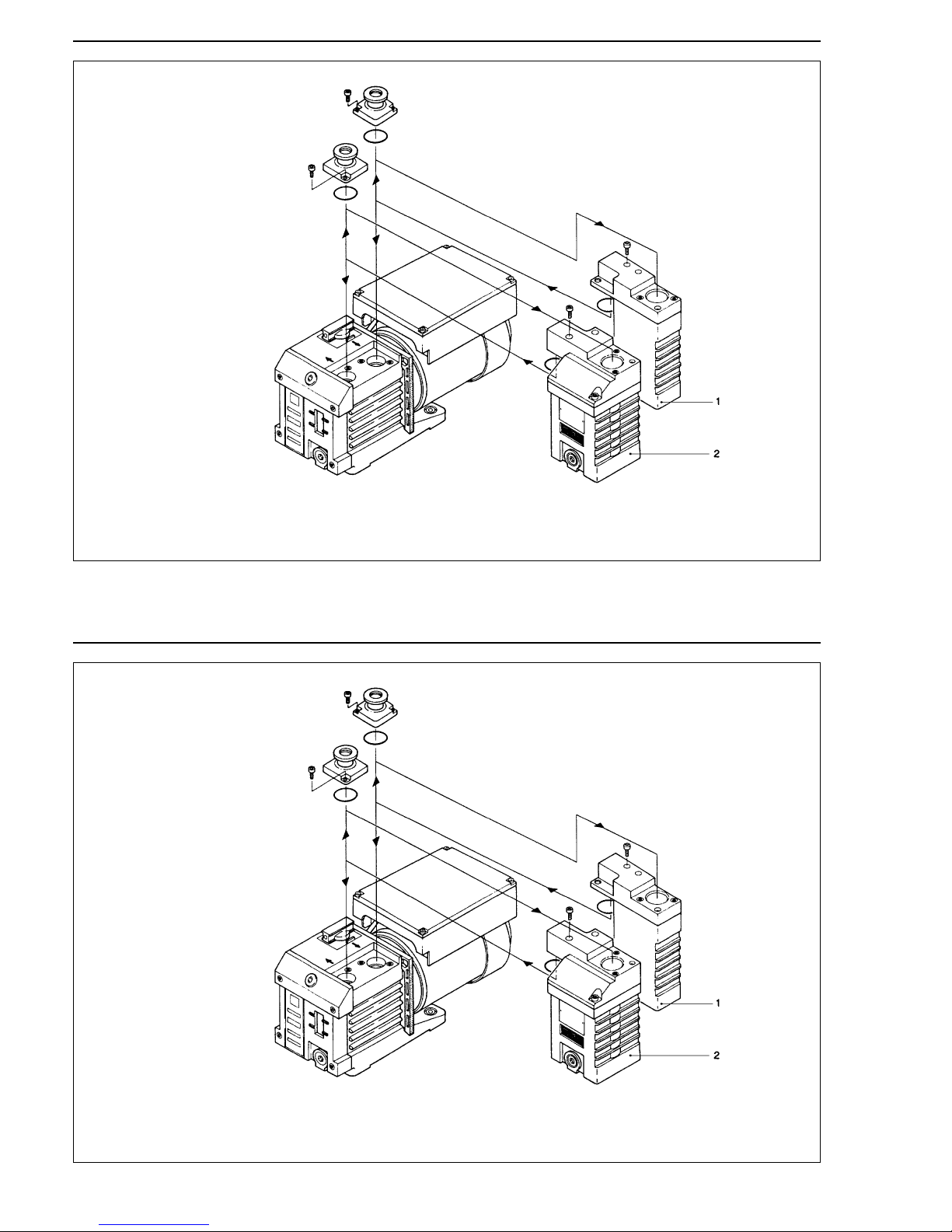
Abb. 2 Anschluß des Abscheiders AK 1,6 und des Auspuff-Filters AF 1,6 an TRIVAC S/D 1,6 B
Erläuterungen zur Abb. 2
1 Abscheider AK 1,6
2 Auspuff-Filter AF 1,6
GA 01.299/7 - 03/99
6
Abb. 2 Anschluß des Abscheiders AK 1,6 und des Auspuff-Filters AF 1,6 an TRIVAC S/D 1,6 B
Erläuterungen zur Abb. 2
1 Abscheider AK 1,6
2 Auspuff-Filter AF 1,6
Page 7
GA 01.299/7 - 03/99
2 Montage
2.1 Montage AK 1,6 und AF 1,6
Auf der Oberseite des Pumpengehäuses nach Bedarf
den Ansaug- und/oder Auspuff-Flansch nach Lösen der
2 Innensechskant-Schrauben entfernen.
Diese Flansche werden anschließend auf den entsprechenden Ansaugkondensator oder Auspuff-Filter wieder
montiert. Zur Montage auf der Pumpe dient der an den
beiden Aggregaten vorhandene Kragen, an dessen
Unterseite der jeweilige Gegenflansch liegt.
Der hierzu notwendige O-Ring sowie zwei weitere
Innensechskant-Schrauben gehören zum Lieferumfang
von AK/AF 1,6.
Soll die TRIVAC S/D 1,6 B lediglich mit dem Ansaugkondensator betrieben werden, so kann der bessere Kontrolle wegen auch das Unterteil des AK 1,6 um 180°
gedreht werden, dazu die beiden durch den Kragen
führenden Innensechskant-Schrauben lösen.
Die Kühlrippen des AK 1,6 liegen dann denen der
Pumpe direkt gegenüber, während das Schauglas der
Pumpe mit dem des AK 1,6 auf einen Blick erfaßt wird.
2.2 Montage AK/AF 4-8, 16-25 und 40-65
Die Strömungsrichtung (durch Pfeil
gekennzeichnet) muß beim Anschluß
beachtet werden.
Den Auspuff-Filter oder Abscheider wie in Abb. 3 dargestellt - direkt an den waagerecht montierten Flansch der
TRIVAC anbauen. Anschlußteile siehe Abschnitt 1.2.
Werden aromatische Dämpfe abgesaugt, empfiehlt sich,
auch bei angebautem Auspuff-Filter, der Anschluß einer
Auspuff-Leitung.
Beim Vorhandensein von giftigen Gasen
und Dämpfen muß eine Auspuff-Leitung
den Sicherheitsvorschriften entsprechend
verlegt werden.
7
Achtung
Vorsicht
GA 01.299/7 - 03/99
2 Montage
2.1 Montage AK 1,6 und AF 1,6
Auf der Oberseite des Pumpengehäuses nach Bedarf
den Ansaug- und/oder Auspuff-Flansch nach Lösen der
2 Innensechskant-Schrauben entfernen.
Diese Flansche werden anschließend auf den entsprechenden Ansaugkondensator oder Auspuff-Filter wieder
montiert. Zur Montage auf der Pumpe dient der an den
beiden Aggregaten vorhandene Kragen, an dessen
Unterseite der jeweilige Gegenflansch liegt.
Der hierzu notwendige O-Ring sowie zwei weitere
Innensechskant-Schrauben gehören zum Lieferumfang
von AK/AF 1,6.
Soll die TRIVAC S/D 1,6 B lediglich mit dem Ansaugkondensator betrieben werden, so kann der bessere Kontrolle wegen auch das Unterteil des AK 1,6 um 180°
gedreht werden, dazu die beiden durch den Kragen
führenden Innensechskant-Schrauben lösen.
Die Kühlrippen des AK 1,6 liegen dann denen der
Pumpe direkt gegenüber, während das Schauglas der
Pumpe mit dem des AK 1,6 auf einen Blick erfaßt wird.
2.2 Montage AK/AF 4-8, 16-25 und 40-65
Die Strömungsrichtung (durch Pfeil
gekennzeichnet) muß beim Anschluß
beachtet werden.
Den Auspuff-Filter oder Abscheider wie in Abb. 3 dargestellt - direkt an den waagerecht montierten Flansch der
TRIVAC anbauen. Anschlußteile siehe Abschnitt 1.2.
Werden aromatische Dämpfe abgesaugt, empfiehlt sich,
auch bei angebautem Auspuff-Filter, der Anschluß einer
Auspuff-Leitung.
Beim Vorhandensein von giftigen Gasen
und Dämpfen muß eine Auspuff-Leitung
den Sicherheitsvorschriften entsprechend
verlegt werden.
7
Achtung
Vorsicht
Page 8
8
GA 01.299/7 - 03/99
Die Stützschrauben am Auspuff-Filter AF 40-65 und am
Abscheider AK 40-65 müssen nach der Montage so verstellt werden, daß sie am Pumpengehäuse anliegen und
das Bauteil abstützt.
Die Flächen der Anschlußflansche müssen
parallel zueinander stehen, und dürfen
nicht verkantet sein.
Achtung
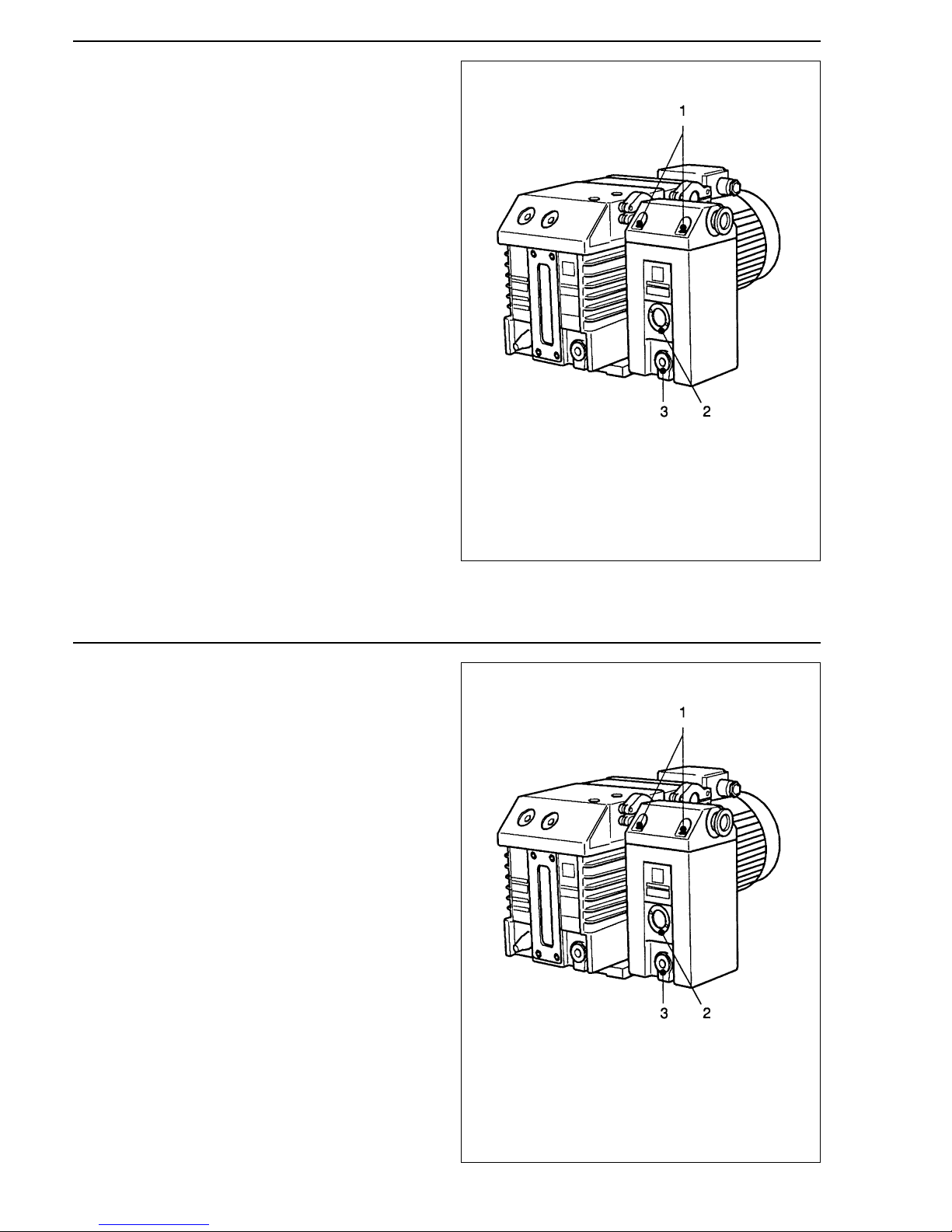
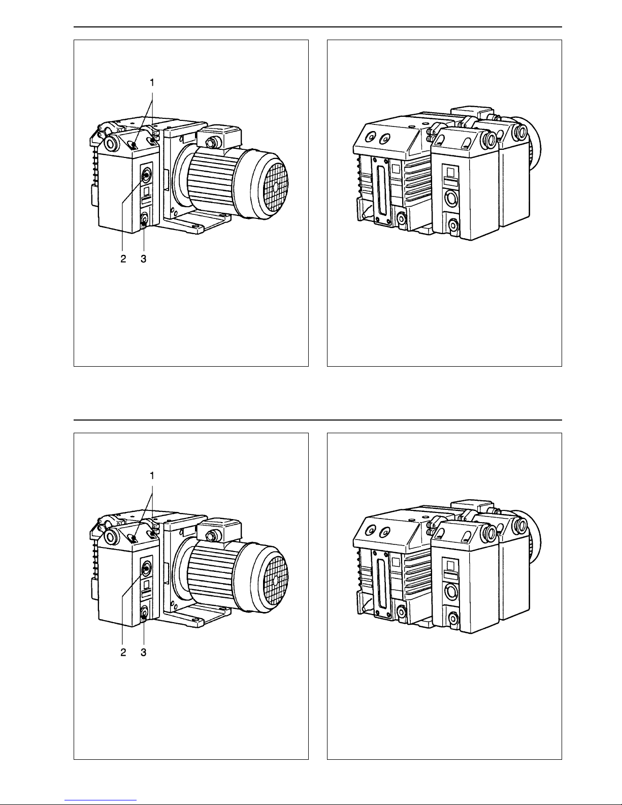
Erläuterungen zur Abb. 3
1 Schrauben am Filterdeckel
2 Schauglas
3 Ablaßschraube
Abb. 3 Drehschieber-Vakuumpumpe TRIVAC
mit angebautem Auspuff-Filter
8
GA 01.299/7 - 03/99
Die Stützschrauben am Auspuff-Filter AF 40-65 und am
Abscheider AK 40-65 müssen nach der Montage so verstellt werden, daß sie am Pumpengehäuse anliegen und
das Bauteil abstützt.
Die Flächen der Anschlußflansche müssen
parallel zueinander stehen, und dürfen
nicht verkantet sein.
Achtung
Erläuterungen zur Abb. 3
1 Schrauben am Filterdeckel
2 Schauglas
3 Ablaßschraube
Abb. 3 Drehschieber-Vakuumpumpe TRIVAC
mit angebautem Auspuff-Filter
Page 9
GA 01.299/7 - 03/99
9
Erläuterungen zur Abb. 4
1 Schrauben am Filterdeckel
2 Schauglas
3 Ablaßschraube
Abb. 4 Drehschieber-Vakuumpumpe TRIVAC
mit angebautem Abscheider
Abb. 5 Drehschieber-Vakuumpumpe TRIVAC
mit angebautem Auspuff-Filter und Abscheider
GA 01.299/7 - 03/99
9
Erläuterungen zur Abb. 4
1 Schrauben am Filterdeckel
2 Schauglas
3 Ablaßschraube
Abb. 4 Drehschieber-Vakuumpumpe TRIVAC
mit angebautem Abscheider
Abb. 5 Drehschieber-Vakuumpumpe TRIVAC
mit angebautem Auspuff-Filter und Abscheider
Page 10
GA 01.299/7 - 03/99
10
3 Wartung
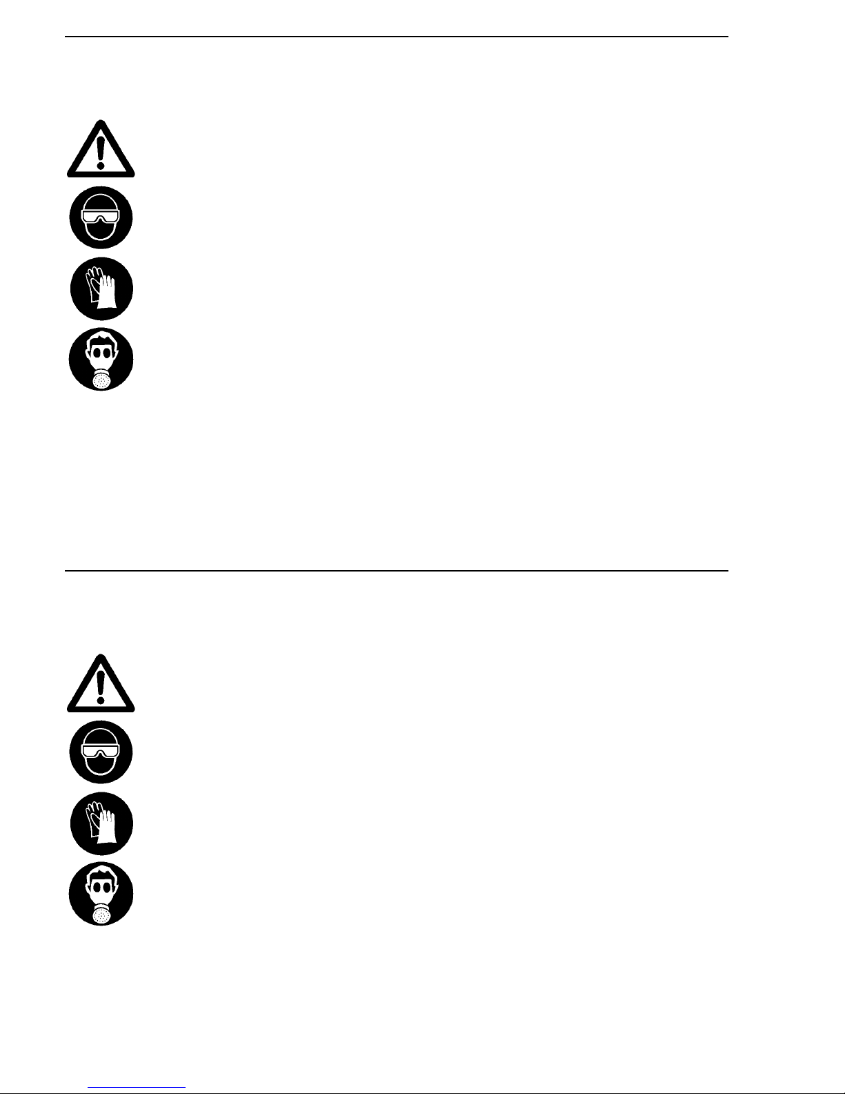
Aus dem Filter, aus dem Kondensat und
aus dem Öl können gefährliche Stoffe entweichen.
Angemessene Sicherheitsvorkehrungen
treffen (z.B. Handschuhe, Gesichtsschutz
oder Atemmaske benutzen.
Die Sicherheitsvorschriften sind zu beachten.
3.1 Auspuff-Filter / Öl ablassen
In regelmäßigen Zeitabständen (abhängig vom Einsatzort der Vakuumpumpe) muß das ausgefilterte Öl aus
dem Sammelraum des Filters abgelassen werden. Dazu
die Ölablaßschraube (3/3) herausschrauben.
Der Ölspiegel darf die Mitte des Schauglases (3/2) nicht
übersteigen. Höherer Ölstand führt zur Überflutung der
Filterelemente.
Durch den Gasstrom können Öltropfen mitgerissen
werden. Außerdem wird durch die Verkleinerung der
wirksamen Filterfläche die Druckdifferenz erhöht, was
zum Öffnen des Überdruckventils führen kann.
Filterelemente Auswechseln
In regelmäßigen Abständen müssen die Filterelemente
ausgetauscht werden. Der Zeitabstand hängt von den
Einsatzbedingungen und der Betriebsart der Vakuumpumpe ab. Je schmutziger der Betrieb und je heißer die
Pumpe, um so kürzer ist der Abstand des nötigen W echsels.
Der Filterwechsel ist in jedem Fall erforderlich, wenn das
Überdruckventil anspricht, wobei vorausgesetzt wird,
daß ausgefiltertes Öl rechtzeitig abgelassen wurde.
Vorsicht
GA 01.299/7 - 03/99
10
3 Wartung
Aus dem Filter, aus dem Kondensat und
aus dem Öl können gefährliche Stoffe entweichen.
Angemessene Sicherheitsvorkehrungen
treffen (z.B. Handschuhe, Gesichtsschutz
oder Atemmaske benutzen.
Die Sicherheitsvorschriften sind zu beachten.
3.1 Auspuff-Filter / Öl ablassen
In regelmäßigen Zeitabständen (abhängig vom Einsatzort der Vakuumpumpe) muß das ausgefilterte Öl aus
dem Sammelraum des Filters abgelassen werden. Dazu
die Ölablaßschraube (3/3) herausschrauben.
Der Ölspiegel darf die Mitte des Schauglases (3/2) nicht
übersteigen. Höherer Ölstand führt zur Überflutung der
Filterelemente.
Durch den Gasstrom können Öltropfen mitgerissen
werden. Außerdem wird durch die Verkleinerung der
wirksamen Filterfläche die Druckdifferenz erhöht, was
zum Öffnen des Überdruckventils führen kann.
Filterelemente Auswechseln
In regelmäßigen Abständen müssen die Filterelemente
ausgetauscht werden. Der Zeitabstand hängt von den
Einsatzbedingungen und der Betriebsart der Vakuumpumpe ab. Je schmutziger der Betrieb und je heißer die
Pumpe, um so kürzer ist der Abstand des nötigen W echsels.
Der Filterwechsel ist in jedem Fall erforderlich, wenn das
Überdruckventil anspricht, wobei vorausgesetzt wird,
daß ausgefiltertes Öl rechtzeitig abgelassen wurde.
Vorsicht
Page 11

GA 01.299/7 - 03/99
11
Zum Auswechseln der Filterelemente die Pumpe
abschalten.
Öl ablassen (3/3) und Ölablaßschraube wieder einschrauben.
Filtergehäuse durch unterlegen von z.B. Holzleisten
abstützen.
4 Schrauben (3/1) herausschrauben und Filtergehäuse
absetzen.
Kleinflansch-Verbindungen zum Auspuffstutzen der
Pumpe und zur Auspuffleitung lösen und den Deckel
abziehen.
Alte Filterelemente durch neue ersetzen.
Beachten Sie bei der Entsorgung von Altöl
und gebrauchten Filterelementen die
geltenden Umweltschutz-Bestimmungen.
Gehäuse-Deckel zwischen Auspuffstutzen der Pumpe
und Auspuffleitung anflanschen.
Filter-Deckel mit einwandfreier Dichtung wieder
anschrauben.
Das Anzugsdrehmoment der Schrauben beträgt 5 Nm.
3.2 Abscheider
In regelmäßigen Zeitabständen (abhängig vom Einsatzort der TRIVAC-Pumpen) muß das angefallene Kondensat abgelassen werden.
Ablaßschraube (4/3) herausschrauben und das Kondensat ablassen.
Bei zu hohem Kondensatstand im Abscheider - Flüssigkeitsoberfläche im Schauglas sichtbar (4/2) - kann dies
in die Pumpe zurückfließen und die Funktion der Pumpe
empfindlich stören.
Achtung
GA 01.299/7 - 03/99
11
Zum Auswechseln der Filterelemente die Pumpe
abschalten.
Öl ablassen (3/3) und Ölablaßschraube wieder einschrauben.
Filtergehäuse durch unterlegen von z.B. Holzleisten
abstützen.
4 Schrauben (3/1) herausschrauben und Filtergehäuse
absetzen.
Kleinflansch-Verbindungen zum Auspuffstutzen der
Pumpe und zur Auspuffleitung lösen und den Deckel
abziehen.
Alte Filterelemente durch neue ersetzen.
Beachten Sie bei der Entsorgung von Altöl
und gebrauchten Filterelementen die
geltenden Umweltschutz-Bestimmungen.
Gehäuse-Deckel zwischen Auspuffstutzen der Pumpe
und Auspuffleitung anflanschen.
Filter-Deckel mit einwandfreier Dichtung wieder
anschrauben.
Das Anzugsdrehmoment der Schrauben beträgt 5 Nm.
3.2 Abscheider
In regelmäßigen Zeitabständen (abhängig vom Einsatzort der TRIVAC-Pumpen) muß das angefallene Kondensat abgelassen werden.
Ablaßschraube (4/3) herausschrauben und das Kondensat ablassen.
Bei zu hohem Kondensatstand im Abscheider - Flüssigkeitsoberfläche im Schauglas sichtbar (4/2) - kann dies
in die Pumpe zurückfließen und die Funktion der Pumpe
empfindlich stören.
Achtung
Page 12
3.3 Service bei Leybold
Falls Sie ein Gerät an Leybold schicken, geben Sie an,
ob es frei von gesundheitsgefährdenden Schadstoffen
ist oder ob es kontaminiert ist.
Wenn es kontaminiert ist geben Sie auch die Art der
Gefährdung an. Dazu müssen Sie ein von uns vorbereitetes Formular benutzen, das wir Ihnen auf Anfrage
zusenden.
Eine Kopie dieses Formulars ist auf Seite 13 dieser
Gebrauchsanleitung abgedruckt: „Erklärung über Kontaminierung von Vakuumgeräten und - komponenten“.
Befestigen Sie das Formular an dem Gerät oder legen
Sie es dem Gerät bei.
Diese Erklärung über Kontaminierung ist erforderlich zur
Erfüllung gesetzlicher Auflagen und zum Schutz unserer
Mitarbeiter.
Geräte ohne Erklärung über Kontaminierung muß
Leybold an den Absender zurückschicken.
Die Geräte so verpacken, daß sie beim
Transport nicht beschädigt werden, und
daß keine Schadstoffe aus der Verpackung
austreten können.
12
GA 01.299/7 - 03/99
Vorsicht
3.3 Service bei Leybold
Falls Sie ein Gerät an Leybold schicken, geben Sie an,
ob es frei von gesundheitsgefährdenden Schadstoffen
ist oder ob es kontaminiert ist.
Wenn es kontaminiert ist geben Sie auch die Art der
Gefährdung an. Dazu müssen Sie ein von uns vorbereitetes Formular benutzen, das wir Ihnen auf Anfrage
zusenden.
Eine Kopie dieses Formulars ist auf Seite 13 dieser
Gebrauchsanleitung abgedruckt: „Erklärung über Kontaminierung von Vakuumgeräten und - komponenten“.
Befestigen Sie das Formular an dem Gerät oder legen
Sie es dem Gerät bei.
Diese Erklärung über Kontaminierung ist erforderlich zur
Erfüllung gesetzlicher Auflagen und zum Schutz unserer
Mitarbeiter.
Geräte ohne Erklärung über Kontaminierung muß
Leybold an den Absender zurückschicken.
Die Geräte so verpacken, daß sie beim
Transport nicht beschädigt werden, und
daß keine Schadstoffe aus der Verpackung
austreten können.
12
GA 01.299/7 - 03/99
Vorsicht
Page 13
13
GA 01.299/7 - 03/99
8
M U S T E R
4. Einsatzbedingte Kontaminierung der Vakuum-
geräte und -komponenten:
- toxisch ja ❒ nein ❒
- ätzend ja ❒ nein ❒
- mikrobiologisch*) ja ❒ nein ❒
- explosiv*) ja ❒ nein ❒
- radioaktiv*) ja ❒ nein ❒
- sonstige Schadstoffe ja ❒ nein ❒
Erklärung über Kontaminierung von Vakuumgeräten und -komponenten
Die Reparatur und/oder die Wartung von Vakuumgeräten und -komponenten wird nur durchgeführt, wenn eine korrekt und
vollständig ausgefüllte Erklärung vorliegt. Ist das nicht der Fall, kommt es zu Verzögerungen der Arbeiten. Wenn die Repara-
tur/Wartung im Herstellerwerk und nicht am Ort ihres Einsatzes erfolgen soll, wird die Sendung gegebenenfalls zurückgewie-
sen.
Diese Erklärung darf nur von autorisiertem Fachpersonal ausgefüllt und unterschrieben werden.
1. Art der Vakuumgeräte und -komponenten:
- Typenbezeichnung: ______________________
- Artikelnummer: ______________________
- Seriennummer: ______________________
- Rechnungsnummer: ______________________
- Lieferdatum: ______________________
2. Grund für die Einsendung:
______________________________________________
______________________________________________
______________________________________________
______________________________________________
______________________________________________
3. Zustand der Vakuumgeräte und -komponenten:
- Waren die Vakuumgeräte und -komponenten in
Betrieb?
ja ❒ nein ❒
- Welches Pumpenöl wurde verwendet ? _________
- Sind die Vakuumgeräte und -komponenten frei von
gesundheitsgefährdenden Schadstoffen?
ja ❒ (weiter siehe Absatz 5)
nein ❒ (weiter siehe Absatz 4)
*) Mikrobiologisch, explosiv oder radioaktiv kontaminierte Vakuumgeräte und -komponenten werden nur bei Nachweis einer
vorschriftsmäßigen Reinigung entgegengenommen!
Art der Schadstoffe oder prozessbedingter, gefährlicher Reaktionsprodukte, mit denen die Vakuumgeräte und -komponenten in
Kontakt kamen:
Handelsname
Produktname Chemische Bezeichnung Gefahrklasse Maßnahmen bei Freiwerden Erste Hilfe
Hersteller (evtl. auch Formel) der Schadstoffe bei Unfällen
1.2.3.4.5.
Verteiler: Blatt 1 (weiß) an den Hersteller oder seinen Beauftragten senden - Blatt 2 (gelb) den Begleitpapieren der Sendung beifügen - Blatt 3 (blau) Kopie für den Versender
5. Rechtsverbindliche Erklärung
Hiermit versichere(n) ich/wir, daß die Angaben in diesem Vordruck korrekt und vollständig sind. Der Versand der kontami-
nierten Vakuumgeräte und -komponenten erfolgt gemäß den gesetzlichen Bestimmungen.
Firma/Institut: ______________________________________________________________________________
Straße: _____________________________ PLZ, Ort: ________________________________
Telefon: ______________________________________________________________________________
Fax: _____________________________ Telex: _________________________________________
Name:
(in Druckbuchstaben) ______________________________________________________________________________
Position: ______________________________________________________________________________
Datum: _____________________________ Firmenstempel
Rechtsverbindliche Unterschrift:
_________________________________________________________________________________________________
Copyright © 1991 by MaschinenbauVerlag GmbH, Lyoner Straße 18, 6000 Frankfurt/M. 71 Bestell-Nr.: 2121
13
GA 01.299/7 - 03/99
8
M U S T E R
4. Einsatzbedingte Kontaminierung der Vakuum-
geräte und -komponenten:
- toxisch ja ❒ nein ❒
- ätzend ja ❒ nein ❒
- mikrobiologisch*) ja ❒ nein ❒
- explosiv*) ja ❒ nein ❒
- radioaktiv*) ja ❒ nein ❒
- sonstige Schadstoffe ja ❒ nein ❒
Erklärung über Kontaminierung von Vakuumgeräten und -komponenten
Die Reparatur und/oder die Wartung von Vakuumgeräten und -komponenten wird nur durchgeführt, wenn eine korrekt und
vollständig ausgefüllte Erklärung vorliegt. Ist das nicht der Fall, kommt es zu Verzögerungen der Arbeiten. Wenn die Repara-
tur/Wartung im Herstellerwerk und nicht am Ort ihres Einsatzes erfolgen soll, wird die Sendung gegebenenfalls zurückgewie-
sen.
Diese Erklärung darf nur von autorisiertem Fachpersonal ausgefüllt und unterschrieben werden.
1. Art der Vakuumgeräte und -komponenten:
- Typenbezeichnung: ______________________
- Artikelnummer: ______________________
- Seriennummer: ______________________
- Rechnungsnummer: ______________________
- Lieferdatum: ______________________
2. Grund für die Einsendung:
______________________________________________
______________________________________________
______________________________________________
______________________________________________
______________________________________________
3. Zustand der Vakuumgeräte und -komponenten:
- Waren die Vakuumgeräte und -komponenten in
Betrieb?
ja ❒ nein ❒
- Welches Pumpenöl wurde verwendet ? _________
- Sind die Vakuumgeräte und -komponenten frei von
gesundheitsgefährdenden Schadstoffen?
ja ❒ (weiter siehe Absatz 5)
nein ❒ (weiter siehe Absatz 4)
*) Mikrobiologisch, explosiv oder radioaktiv kontaminierte Vakuumgeräte und -komponenten werden nur bei Nachweis einer
vorschriftsmäßigen Reinigung entgegengenommen!
Art der Schadstoffe oder prozessbedingter, gefährlicher Reaktionsprodukte, mit denen die Vakuumgeräte und -komponenten in
Kontakt kamen:
Handelsname
Produktname Chemische Bezeichnung Gefahrklasse Maßnahmen bei Freiwerden Erste Hilfe
Hersteller (evtl. auch Formel) der Schadstoffe bei Unfällen1.2.3.4.
5.
Verteiler: Blatt 1 (weiß) an den Hersteller oder seinen Beauftragten senden - Blatt 2 (gelb) den Begleitpapieren der Sendung beifügen - Blatt 3 (blau) Kopie für den Versender
5. Rechtsverbindliche Erklärung
Hiermit versichere(n) ich/wir, daß die Angaben in diesem Vordruck korrekt und vollständig sind. Der Versand der kontami-
nierten Vakuumgeräte und -komponenten erfolgt gemäß den gesetzlichen Bestimmungen.
Firma/Institut: ______________________________________________________________________________
Straße: _____________________________ PLZ, Ort: ________________________________
Telefon: ______________________________________________________________________________
Fax: _____________________________ Telex: _________________________________________
Name:
(in Druckbuchstaben) ______________________________________________________________________________
Position: ______________________________________________________________________________
Datum: _____________________________ Firmenstempel
Rechtsverbindliche Unterschrift:
_________________________________________________________________________________________________
Copyright © 1991 by MaschinenbauVerlag GmbH, Lyoner Straße 18, 6000 Frankfurt/M. 71 Bestell-Nr.: 2121
Page 14
14
GA 01.299/7 - 03/99
Contents
Page
1 Description . . . . . . . . . . . . . . . . . . . . . . . . .15
1.1 Design and Function . . . . . . . . . . . . . . . . . . .15
1.2 Technical Data . . . . . . . . . . . . . . . . . . . . . . .16
2 Installation . . . . . . . . . . . . . . . . . . . . . . . . .19
2.1 Mounting AK 1.6 and AF 1.6 . . . . . . . . . . . . .19
2.2 Mounting AK/AF 4-8, 16-25 and 40-65 . . . . .19
3 Maintenance . . . . . . . . . . . . . . . . . . . . . . . .22
3.1 Exhaust Filters . . . . . . . . . . . . . . . . . . . . . . .22
3.2 Condensate Traps . . . . . . . . . . . . . . . . . . . .23
3.3 Service at Leybold’s . . . . . . . . . . . . . . . . . .24
Figures
The references to figures, e.g. (1/2) consist of the Fig.
No. and the Item No. in that order.
Leybold Service
If equipment is returned to Leybold, indicate whether the
equipment free of substances damaging to health or
whether it is contaminated.
If it is contaminated also indicate the nature of the
hazard. Leybold must return any equipment without a
“Declaration of Contamination” to the sender’s address.
Indicates procedures that must be strictly
observed to prevent hazards to persons.
Indicates procedures that must strictly be
observed to prevent damage to, or destruction of the equipment.
We reserve the right to modify the design and the specified data. The illustrations are not binding.
Warning
Caution
14
GA 01.299/7 - 03/99
Contents
Page
1 Description . . . . . . . . . . . . . . . . . . . . . . . . .15
1.1 Design and Function . . . . . . . . . . . . . . . . . . .15
1.2 Technical Data . . . . . . . . . . . . . . . . . . . . . . .16
2 Installation . . . . . . . . . . . . . . . . . . . . . . . . .19
2.1 Mounting AK 1.6 and AF 1.6 . . . . . . . . . . . . .19
2.2 Mounting AK/AF 4-8, 16-25 and 40-65 . . . . .19
3 Maintenance . . . . . . . . . . . . . . . . . . . . . . . .22
3.1 Exhaust Filters . . . . . . . . . . . . . . . . . . . . . . .22
3.2 Condensate Traps . . . . . . . . . . . . . . . . . . . .23
3.3 Service at Leybold’s . . . . . . . . . . . . . . . . . .24
Figures
The references to figures, e.g. (1/2) consist of the Fig.
No. and the Item No. in that order.
Leybold Service
If equipment is returned to Leybold, indicate whether the
equipment free of substances damaging to health or
whether it is contaminated.
If it is contaminated also indicate the nature of the
hazard. Leybold must return any equipment without a
“Declaration of Contamination” to the sender’s address.
Indicates procedures that must be strictly
observed to prevent hazards to persons.
Indicates procedures that must strictly be
observed to prevent damage to, or destruction of the equipment.
We reserve the right to modify the design and the specified data. The illustrations are not binding.
Warning
Caution
Page 15
1 Description
1.1 Design and Function
Exhaust Filters
In the exhaust filters oil mist and aerosols are trapped,
whereas easily volatile substances and aromatics pass
through the filter.
The gas discharged by the vacuum pump flows through
the filter element where smallest oil drops and dirt particels contained in the gas are trapped. The separated oil
drops are collected in the exhaust filter.
In the exhaust filter AF 40-65 two filter elements are
arranged in parallel.
Filter elements may get clogged in the long run due to
crack products in the oil, and this may cause overpressure to build up in the pump. In order to make sure that
the pressure will not exceed an admissible value
(approx. 1.5 bar) a pressure relief valve is provided on
the exhaust filter.
If the filterelement should have become clogged,the builtin pressure relief valve opens so that the oil mist expelled by the pump is conducted into the open air. In this
way any damage which might be caused by overpressure is safely excluded.
An exhaust line fulfilling the safety requirements concerned is imperative if poisonous
gases or vapours are filtered.
Observe the applicable safety regulations
for the media which are pumped.
Condensate Traps
Condensate traps mounted into the intake line protect
the pump from condensates which might result from the
pumped vapors and gases.
Condensate traps mounted into the exhaust line protect
against backflow of liquids which might condense in the
outlet line.
Condensate traps can be fitted optionally on the intake
and/or exhaust side of a TRIVAC pump.
15
GA 01.299/7 - 03/99
Warning
1 Description
1.1 Design and Function
Exhaust Filters
In the exhaust filters oil mist and aerosols are trapped,
whereas easily volatile substances and aromatics pass
through the filter.
The gas discharged by the vacuum pump flows through
the filter element where smallest oil drops and dirt particels contained in the gas are trapped. The separated oil
drops are collected in the exhaust filter.
In the exhaust filter AF 40-65 two filter elements are
arranged in parallel.
Filter elements may get clogged in the long run due to
crack products in the oil, and this may cause overpressure to build up in the pump. In order to make sure that
the pressure will not exceed an admissible value
(approx. 1.5 bar) a pressure relief valve is provided on
the exhaust filter.
If the filterelement should have become clogged,the builtin pressure relief valve opens so that the oil mist expelled by the pump is conducted into the open air. In this
way any damage which might be caused by overpressure is safely excluded.
An exhaust line fulfilling the safety requirements concerned is imperative if poisonous
gases or vapours are filtered.
Observe the applicable safety regulations
for the media which are pumped.
Condensate Traps
Condensate traps mounted into the intake line protect
the pump from condensates which might result from the
pumped vapors and gases.
Condensate traps mounted into the exhaust line protect
against backflow of liquids which might condense in the
outlet line.
Condensate traps can be fitted optionally on the intake
and/or exhaust side of a TRIVAC pump.
15
GA 01.299/7 - 03/99
Warning
Page 16
16
GA 01.299/7 - 03/99
1.2 Technical Data
Exhaust filter AF 1,5 AF 4-8 AF 16-25 AF 40-65
Used on pump S/D 1,6 B S/D 4 B S/D 16 B/BCS S/D 40 B/BCS
S/D 8 B S/D 25 B/BCS S/D 65 B/BCS
Connecting flanges DN 16 KF DN 16 KF DN 25 KF DN 40 KF
Max. capacity 0,1 l 0,37 l 0,48 l 1,0 l
Weight 0,9 kg 2,4 kg 2,4 kg 6,5 kg
Exhaust filter, cat. no. 189 02 189 06 189 11 189 16
Spare filter element, cat. no. 189 70 189 71 189 72 189 73 (2x)
Separator AK 1,5 AK 4-8 AK 16-25 AK 40-65
Used on pump S/D 1,6 B S/D 4 B S/D 16 B/BCS S/D 40 B/BCS
S/D 8 B S/D 25 B/BCS S/D 65 B/BCS
Connecting flanges DN 16 KF DN 16 KF DN 25 KF DN 40 KF
Max. capacity 0,16 l 0,66 l 1,2 l 3,0 l
Weight 0,7 kg 1,7 kg 2,4 kg 5,5 kg
Separator, cat. no. 188 02 188 06 188 11 188 16
Accessories
Drain tap 188 90 188 90 188 90 188 90
Drain tap, vacuum-tight 188 91 188 91 188 91 188 91
Centering ring 183 26 183 26 183 27 183 28
Clamping ring 183 41 183 41 183 42 183 43
16
GA 01.299/7 - 03/99
1.2 Technical Data
Exhaust filter AF 1,5 AF 4-8 AF 16-25 AF 40-65
Used on pump S/D 1,6 B S/D 4 B S/D 16 B/BCS S/D 40 B/BCS
S/D 8 B S/D 25 B/BCS S/D 65 B/BCS
Connecting flanges DN 16 KF DN 16 KF DN 25 KF DN 40 KF
Max. capacity 0,1 l 0,37 l 0,48 l 1,0 l
Weight 0,9 kg 2,4 kg 2,4 kg 6,5 kg
Exhaust filter, cat. no. 189 02 189 06 189 11 189 16
Spare filter element, cat. no. 189 70 189 71 189 72 189 73 (2x)
Separator AK 1,5 AK 4-8 AK 16-25 AK 40-65
Used on pump S/D 1,6 B S/D 4 B S/D 16 B/BCS S/D 40 B/BCS
S/D 8 B S/D 25 B/BCS S/D 65 B/BCS
Connecting flanges DN 16 KF DN 16 KF DN 25 KF DN 40 KF
Max. capacity 0,16 l 0,66 l 1,2 l 3,0 l
Weight 0,7 kg 1,7 kg 2,4 kg 5,5 kg
Separator, cat. no. 188 02 188 06 188 11 188 16
Accessories
Drain tap 188 90 188 90 188 90 188 90
Drain tap, vacuum-tight 188 91 188 91 188 91 188 91
Centering ring 183 26 183 26 183 27 183 28
Clamping ring 183 41 183 41 183 42 183 43
Page 17
GA 01.299/7 - 03/99
17
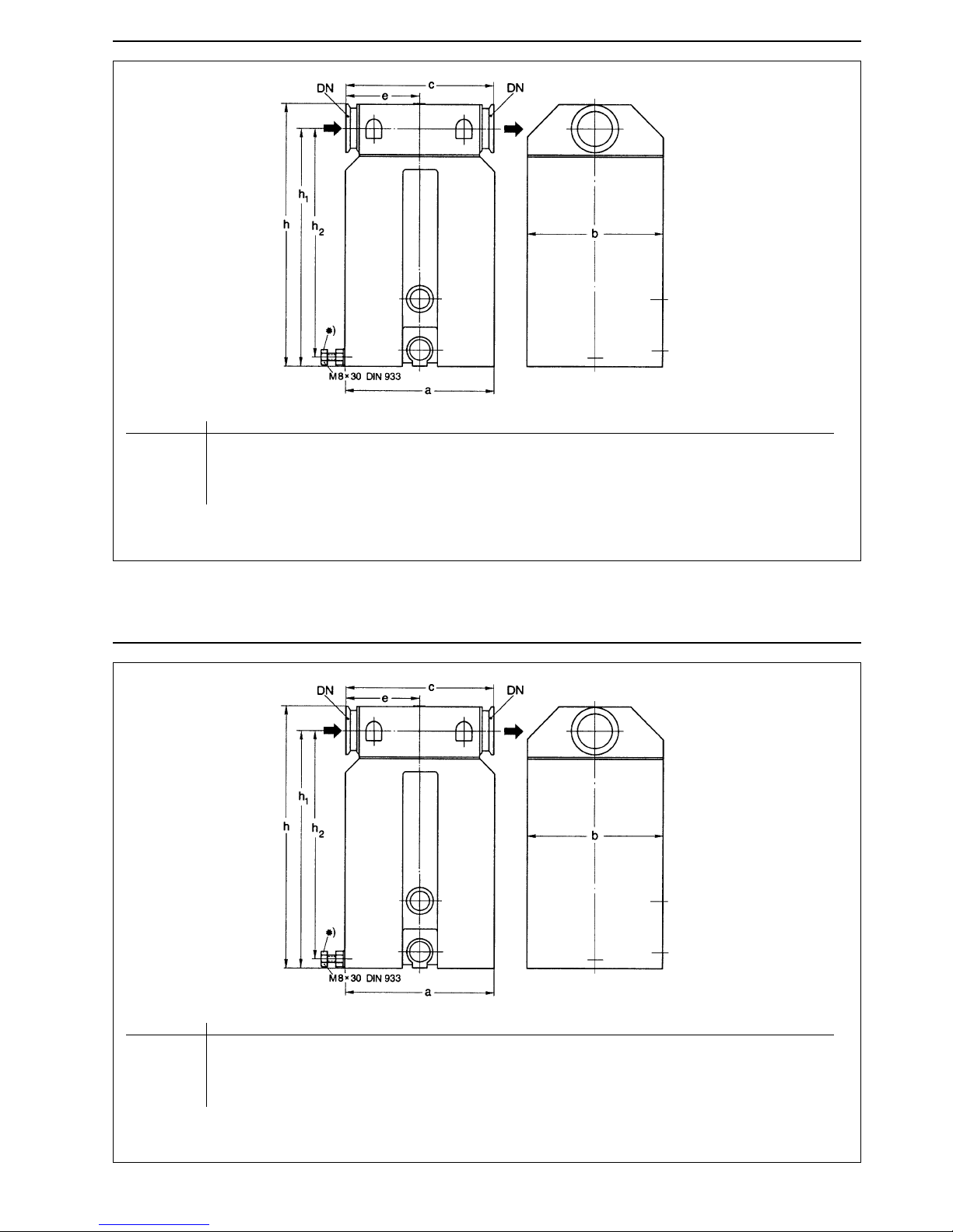
Fig. 1 Dimensional drawings of the exhaust filters, separator similar, dimensions in mm (inch)
DN a b c e h h1 h2
AF/AK 1,6 16 KF 73 (2
7
/8) 72 (43) 76 (3) 25 (1) 164 (6 15/32) 149 (5 7/8)-
AF/AK 4-8 16 KF 90 (3
9
/16) 90 (3 9/16) 120 (4 3/4) 60 (2 3/8) 194 (7 21/32) 178 (7) -
AF/AK 16-25 25 KF 110 (4
11
/32) 125 (4 15/16) 142 (5 19/32) 71 (2 13/16) 214 (8 7/16) 193 (7 19/32)-
AF/AK 40-65* 40 KF 140 (5
17
/32) 156 (6 5/32) 170 (6 23/32) 85 (3 11/32) 300 (11 13/16) 271 (10 11/16) 261 (10 9/32)
GA 01.299/7 - 03/99
17
Fig. 1 Dimensional drawings of the exhaust filters, separator similar, dimensions in mm (inch)
DN a b c e h h1 h2
AF/AK 1,6 16 KF 73 (2
7
/8) 72 (43) 76 (3) 25 (1) 164 (6 15/32) 149 (5 7/8)-
AF/AK 4-8 16 KF 90 (3
9
/16) 90 (3 9/16) 120 (4 3/4) 60 (2 3/8) 194 (7 21/32) 178 (7) -
AF/AK 16-25 25 KF 110 (4
11
/32) 125 (4 15/16) 142 (5 19/32) 71 (2 13/16) 214 (8 7/16) 193 (7 19/32)-
AF/AK 40-65* 40 KF 140 (5
17
/32) 156 (6 5/32) 170 (6 23/32) 85 (3 11/32) 300 (11 13/16) 271 (10 11/16) 261 (10 9/32)
Page 18
GA 01.299/7 - 03/99
18
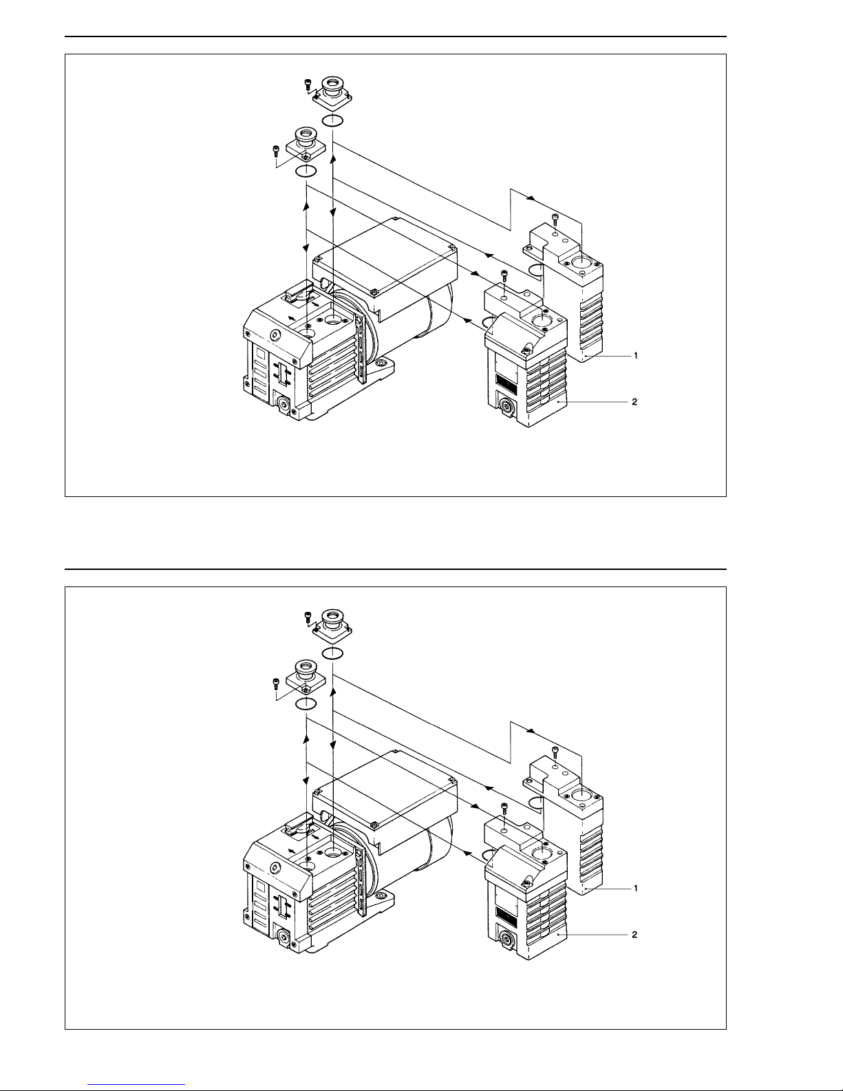
Fig. 2 Connection of the separator AK 1.6 and the exhaust filter AF 1.6 to TRIVAC S/D 1.6 B
Key to Fig. 2
1 Separator AK 1,6
2 Exhaust filter AF 1,6
GA 01.299/7 - 03/99
18
Fig. 2 Connection of the separator AK 1.6 and the exhaust filter AF 1.6 to TRIVAC S/D 1.6 B
Key to Fig. 2
1 Separator AK 1,6
2 Exhaust filter AF 1,6
Page 19
GA 01.299/7 - 03/99
2 Installation
2.1 Mounting AK 1.6 and AF 1.6
Remove inlet and/or outlet port connection, as required,
on top of pump body , undoing two each hex socket head
screws (Allen screws). The same connection are then
fitted on top of connected intake-side condensate trap or
exhaust-side filter. Mount trap and/or filter on the pump
by the counter flange at the underside of the connecting
yoke. The necessary O-ring and two additional Allen
screws are supplied with the trap and filter.
If the TRIVAC S/D 1.6 B pump is used with condensate
trap only, the lower part of the AK 1.6 may be turned
round to facilitate condensate-level-checking, unscrewing the two Allen screws through the upper yoke.
The cooling ribs of the AK 1.6 are therby placed directly
opposite to those of the pump, while the inspection
window, together with the oil level indicator of the pump,
can be checked at a glance.
2.2 Mounting AK/AF 4-8, 16-25 and 40-65
The direction of flow is marked by an arrow
and must be observed when connecting
the filter.
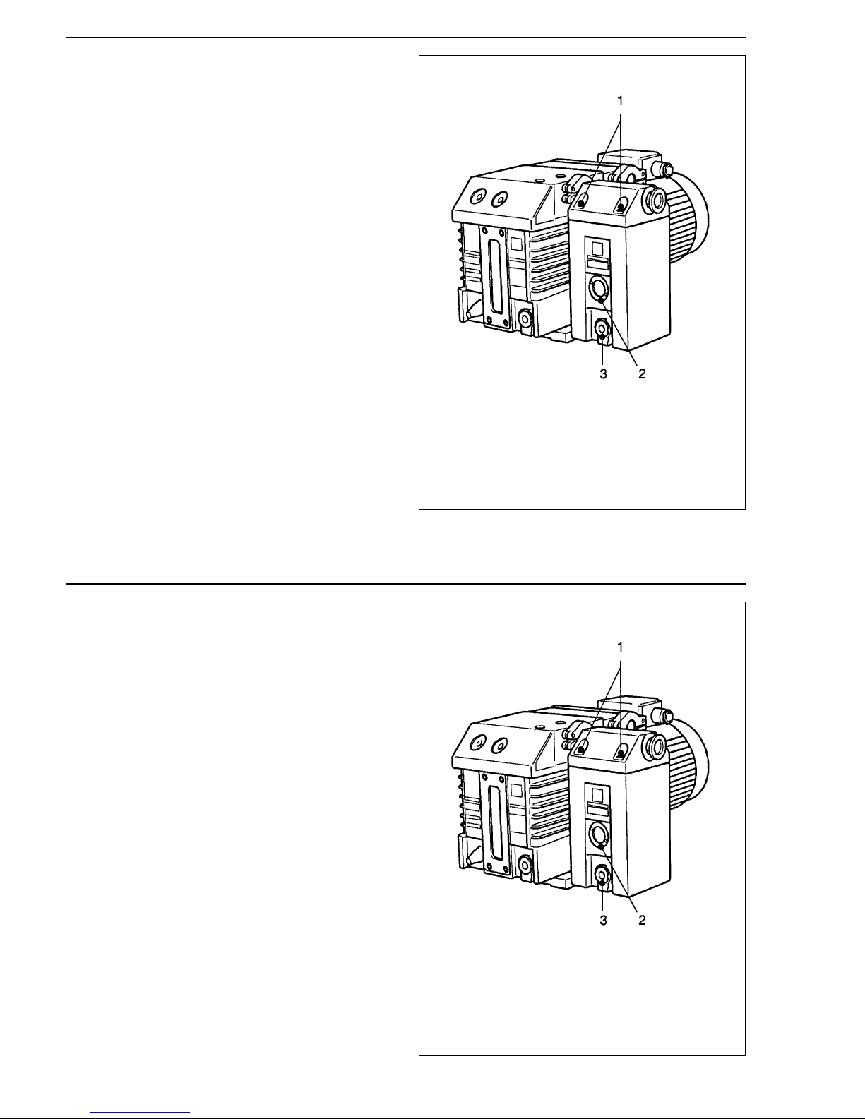
As shown in Fig. 3, fit the exhaust filter or the separator
directly on the horizontally mounted flange of the
TRIVAC. For connection fittings refer to Section 1.2.
When aromatic vapors are pumped, we recommend
fitting an exhaust line even in case of optionally mounted
exhaust filters.
When toxic gases or vapors are pumped,
an exhaust line must be fitted in accordance with the safety regulations relating to
protection against poisonous vapors.
19
Warning
Warning
GA 01.299/7 - 03/99
2 Installation
2.1 Mounting AK 1.6 and AF 1.6
Remove inlet and/or outlet port connection, as required,
on top of pump body , undoing two each hex socket head
screws (Allen screws). The same connection are then
fitted on top of connected intake-side condensate trap or
exhaust-side filter. Mount trap and/or filter on the pump
by the counter flange at the underside of the connecting
yoke. The necessary O-ring and two additional Allen
screws are supplied with the trap and filter.
If the TRIVAC S/D 1.6 B pump is used with condensate
trap only, the lower part of the AK 1.6 may be turned
round to facilitate condensate-level-checking, unscrewing the two Allen screws through the upper yoke.
The cooling ribs of the AK 1.6 are therby placed directly
opposite to those of the pump, while the inspection
window, together with the oil level indicator of the pump,
can be checked at a glance.
2.2 Mounting AK/AF 4-8, 16-25 and 40-65
The direction of flow is marked by an arrow
and must be observed when connecting
the filter.
As shown in Fig. 3, fit the exhaust filter or the separator
directly on the horizontally mounted flange of the
TRIVAC. For connection fittings refer to Section 1.2.
When aromatic vapors are pumped, we recommend
fitting an exhaust line even in case of optionally mounted
exhaust filters.
When toxic gases or vapors are pumped,
an exhaust line must be fitted in accordance with the safety regulations relating to
protection against poisonous vapors.
19
Warning
Warning
Page 20
20
GA 01.299/7 - 03/99
After mounting to the pump, adjust the supporting
screw of AF 40-65 exhaust filter and AK 40-65 condensate trap so that it is firmly positioned on the pump housing, thus supporting the connected component.
The connecting flange faces must be in
parallel to each other - no tilting !
Caution
Key to Fig. 3
1 Bolts on filter flange
2 Level glass
3 Drain plug
Fig. 3 TRIVAC rotary vane vacuum pump with
exhaust filter fitted on
20
GA 01.299/7 - 03/99
After mounting to the pump, adjust the supporting
screw of AF 40-65 exhaust filter and AK 40-65 condensate trap so that it is firmly positioned on the pump housing, thus supporting the connected component.
The connecting flange faces must be in
parallel to each other - no tilting !
Caution
Key to Fig. 3
1 Bolts on filter flange
2 Level glass
3 Drain plug
Fig. 3 TRIVAC rotary vane vacuum pump with
exhaust filter fitted on
Page 21
GA 01.299/7 - 03/99
21
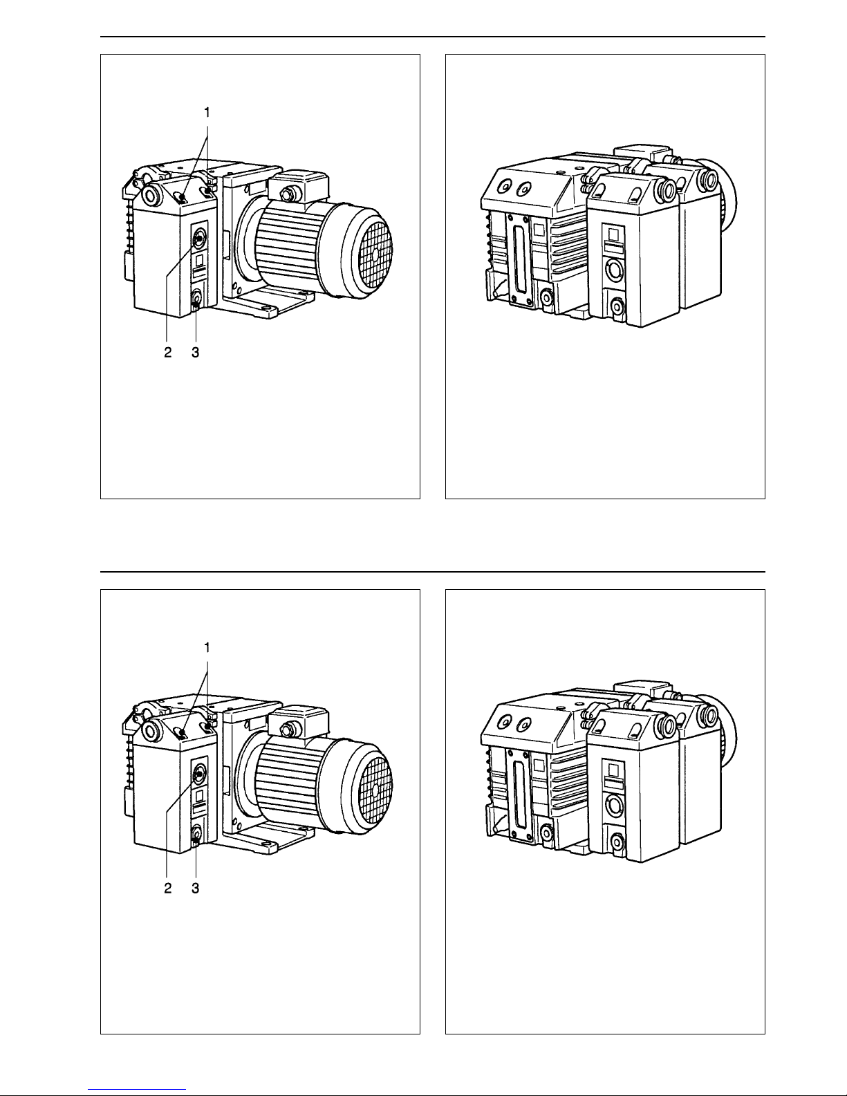
Key to Fig. 4
1 Bolts on filter flange
2 Level glass
3 Drain plug
Fig. 4 TRIVAC rotary vane vacuum pump with
condensate trap fitted on
Fig. 5 TRIVAC rotary vane vacuum pump with
exhaust filter and condensate trap fitted on
GA 01.299/7 - 03/99
21
Key to Fig. 4
1 Bolts on filter flange
2 Level glass
3 Drain plug
Fig. 4 TRIVAC rotary vane vacuum pump with
condensate trap fitted on
Fig. 5 TRIVAC rotary vane vacuum pump with
exhaust filter and condensate trap fitted on
Page 22
22
GA 01.299/7 - 03/99
3 Maintenance
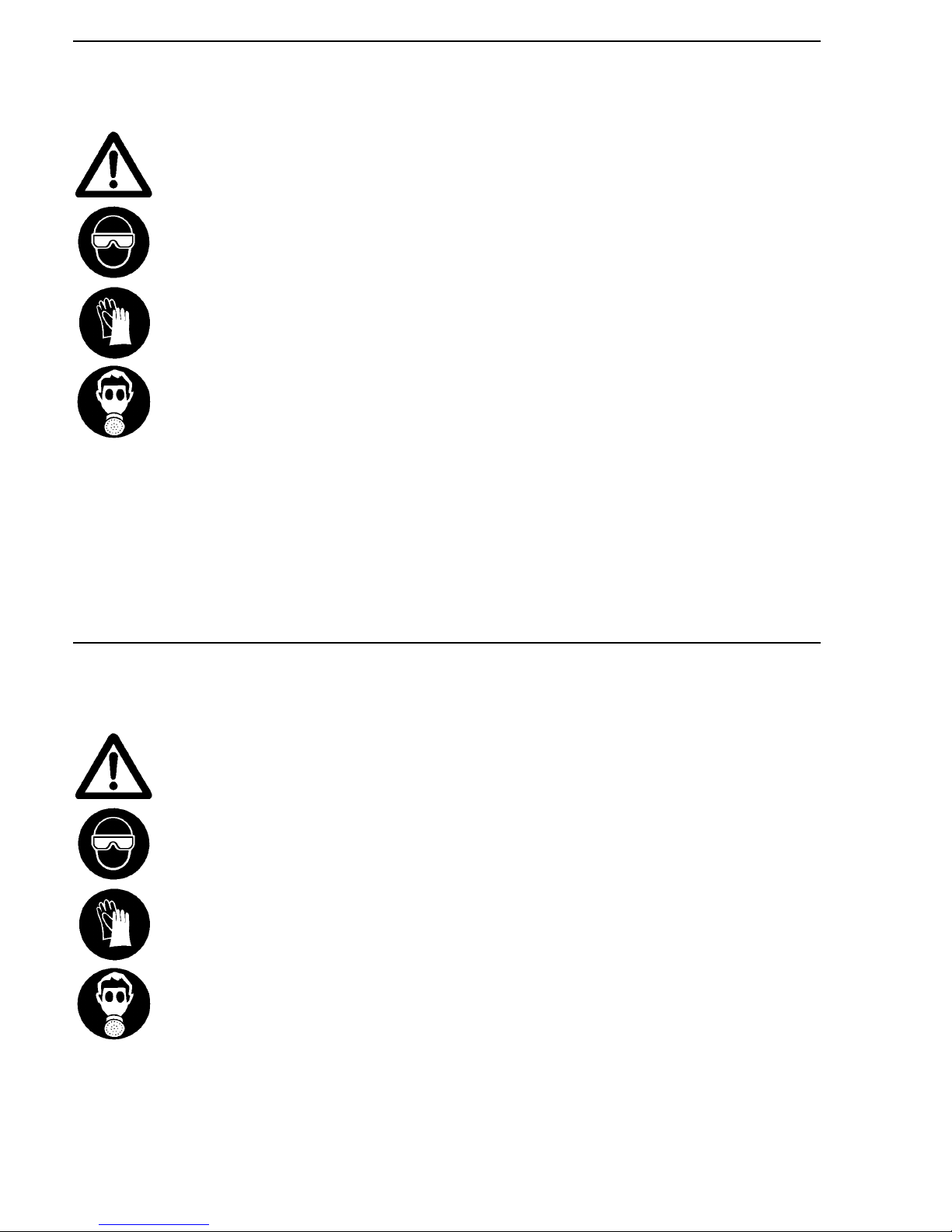
Hazardous substances may escape from
the filter, condensate or the oil.
Take suitable precautions (e. 9. gloves,
goggles or gas mask). Observe all safety
regulations.
3.1 Exhaust Filters / Draining the Oil
The filtered-out quantity of oil must be drained from the
filter at regular intervals depending on the operating
conditions of the pump. For this purpose unscrew oil
drain plug (3/3).
The oil must not rise above the centre of the oil level
glass (3/2). At higher oil level the filter elements may be
flooded causing oil drops to be entrained by the gas
stream.
Apart from this reduction of the effective filter area will
increase the differential pressure which might cause the
pressure relief valve to open.
Replacement of filter elements
The filter elements must be replaced from time to time.
The time interval depends on the application and the
operating conditions of the vacuum pump. The higher
the degree of contamination during operation and the
hotter the pump, the shorter the time interval for replacing the filter elements.
They should be replaced in any case if the pressure
relief valve opens while the oil has been duly drained
from the filter.
Warning
22
GA 01.299/7 - 03/99
3 Maintenance
Hazardous substances may escape from
the filter, condensate or the oil.
Take suitable precautions (e. 9. gloves,
goggles or gas mask). Observe all safety
regulations.
3.1 Exhaust Filters / Draining the Oil
The filtered-out quantity of oil must be drained from the
filter at regular intervals depending on the operating
conditions of the pump. For this purpose unscrew oil
drain plug (3/3).
The oil must not rise above the centre of the oil level
glass (3/2). At higher oil level the filter elements may be
flooded causing oil drops to be entrained by the gas
stream.
Apart from this reduction of the effective filter area will
increase the differential pressure which might cause the
pressure relief valve to open.
Replacement of filter elements
The filter elements must be replaced from time to time.
The time interval depends on the application and the
operating conditions of the vacuum pump. The higher
the degree of contamination during operation and the
hotter the pump, the shorter the time interval for replacing the filter elements.
They should be replaced in any case if the pressure
relief valve opens while the oil has been duly drained
from the filter.
Warning
Page 23
GA 01.299/7 - 03/99
23
For replacing the filter elements shut down the pump.
Drain the oil (3/3) and reinsert the oil drain plug.
Support the filter housing by placing, say, wooden strips
underneath.
Remove 4 screws (3/1) and put down the filter housing.
Loosen the small-flange connections to the pump's
exhaust port and exhaust line and remove the lid.
Replace the used filter elements with new ones.
When disposing of used oil and spent filter
elements, please observe the relevant
environmental protection regulations.
Mount the housing lid between the pump's exhaust port
and line.
Rescrew the filter lid with a gasket that is in perfect
condition.
The starting torque of the screws is 5 Nm.
3.2 Condensate Traps
The accumulating condensate must be drained at regular intervals (depending on the application of the TRIV AC
pumps).
Unscrew the drain plug (4/3) and drain the condensate.
If the condensate level in the trap is too high - liquid level
visible in the inspection window (4/2) - it may flow back
into the pump affecting its operation severely.
Warning
GA 01.299/7 - 03/99
23
For replacing the filter elements shut down the pump.
Drain the oil (3/3) and reinsert the oil drain plug.
Support the filter housing by placing, say, wooden strips
underneath.
Remove 4 screws (3/1) and put down the filter housing.
Loosen the small-flange connections to the pump's
exhaust port and exhaust line and remove the lid.
Replace the used filter elements with new ones.
When disposing of used oil and spent filter
elements, please observe the relevant
environmental protection regulations.
Mount the housing lid between the pump's exhaust port
and line.
Rescrew the filter lid with a gasket that is in perfect
condition.
The starting torque of the screws is 5 Nm.
3.2 Condensate Traps
The accumulating condensate must be drained at regular intervals (depending on the application of the TRIV AC
pumps).
Unscrew the drain plug (4/3) and drain the condensate.
If the condensate level in the trap is too high - liquid level
visible in the inspection window (4/2) - it may flow back
into the pump affecting its operation severely.
Warning
Page 24
24
GA 01.299/7 - 03/99
3.3 Leybold Service
If equipment is returned to Leybold, indicate whether the
equipment free of substances damaging to health or
whether it is contaminated.
If it is contaminated also indicate the nature of the
hazard. For this you must use a form which has been
prepared by us which we will provide upon request.
A copy of this form is reproduced at the end of these
Operating Instructions: “Declaration of Contamination of
Vacuum Instruments and Components”.
Please attach this form to the equipment or enclose it
with the equipment.
This declaration of contamination is required to meet
German Law and to protect our personnel.
Leybold must return any equipment without a “Declaration of Contamination” to the sender’s address.
The equipment must be packed in such a
way , that it will not be damaged during shipping and so that any contaminants are not
released from the package.
Warning
24
GA 01.299/7 - 03/99
3.3 Leybold Service
If equipment is returned to Leybold, indicate whether the
equipment free of substances damaging to health or
whether it is contaminated.
If it is contaminated also indicate the nature of the
hazard. For this you must use a form which has been
prepared by us which we will provide upon request.
A copy of this form is reproduced at the end of these
Operating Instructions: “Declaration of Contamination of
Vacuum Instruments and Components”.
Please attach this form to the equipment or enclose it
with the equipment.
This declaration of contamination is required to meet
German Law and to protect our personnel.
Leybold must return any equipment without a “Declaration of Contamination” to the sender’s address.
The equipment must be packed in such a
way , that it will not be damaged during shipping and so that any contaminants are not
released from the package.
Warning
Page 25
25
GA 01.299/7 - 03/99
S A M P L E
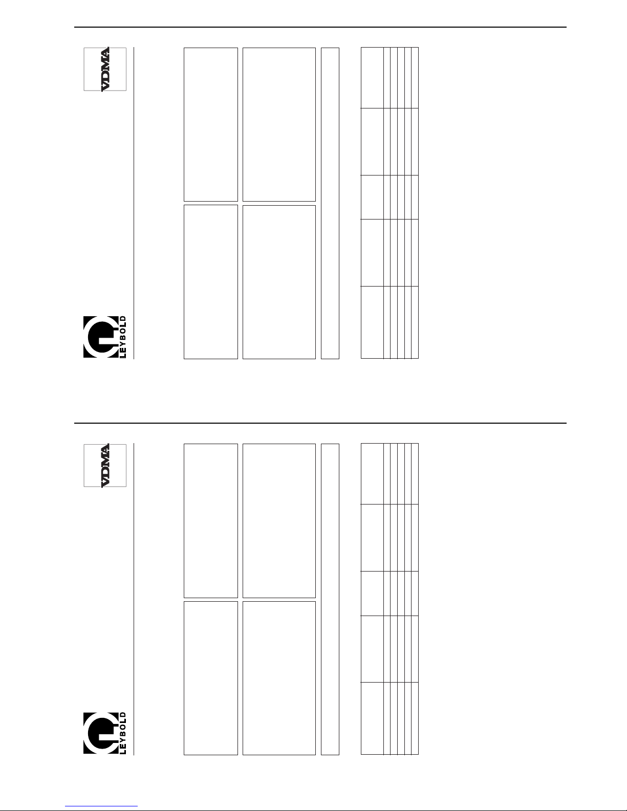
Declaration of Contamination of Vacuum Equipment and Components
The repair and/or service of vacuum equipment and components will only be carried out if a correctly completed declaration has
been submitted. Non-completion will result in delay. The manufacturer could refuse to accept any equipment without a declara-
tion.
This declaration can only be completed and signed by authorized and qualified staff.
1. Description of Vacuum Equipment and Com-
ponents
- Equipment type/model: _________________________________
- Code No.: _________________________________
- Serial No.: _________________________________
- Invoice No.: _________________________________
- Delivery date:
__________________________
2. Reason for Return
____________________________________________
____________________________________________
____________________________________________
____________________________________________
____________________________________________
____________________________________________
3. Condition of the Vacuum Equipment and Com-
ponents
- Has the equipment been used?
yes ❒ no ❒
- What type of pump oil/liquid was used? _________
- Is the equipment free from potentially
harmful substances?
yes ❒ (go to Section 5)
no ❒ (go to Section 4)
4. Process related Contamination of Vacuum
Equipment and Components:
- toxic yes ❒ no ❒
- corrosive yes ❒ no ❒
- explosive*) yes ❒ no ❒
- biological hazard*) yes ❒ no ❒
- radioactive*) yes ❒ no ❒
- other harmful substances yes ❒ no ❒
*) Vacuum equipment and components which have been contaminated by biological explosive or radioactive substances,
will not accepted without written evidence of decontamination!
Please list all substances, gases and by-products which may have come into contact with the equipment:
Trade name
Product name Chemical name Dangerous Measures First aid in case of
Manufacturer (or Symbol) material class if spillage human contact1.2.3.4.
5.
Copies: Page 1 (white) to manufacturer or representative - Page 2 (yellow) attach to consignment packaging securety - Page 3 (blue) copy for file of sender
5. Legally Binding Declaration
I hereby declare that the information supplied on this form is complete and accurate. The despatch of the contaminated
vacuum equipment and components will be in accordance with the appropriate regulations covering Packaging, Transpor-
tation and Labelling of Dangerous Substances.
Name of organisation or company:_____________________________________________________________________
Address: _____________________________ Post code:______________________________________
Tel.: ______________________________________________________________________________
Fax: _____________________________ Telex: _________________________________________
Name: ______________________________________________________________________________
Job title: ______________________________________________________________________________
Date: _____________________________ Company stamp:
Legally binding signature:____________________________________________________________________________
Copyright © 1991 by MaschinenbauVerlag GmbH, Lyoner Straße 18, 6000 Frankfurt/M. 71 Order No.: 2121
25
GA 01.299/7 - 03/99
S A M P L E
Declaration of Contamination of Vacuum Equipment and Components
The repair and/or service of vacuum equipment and components will only be carried out if a correctly completed declaration has
been submitted. Non-completion will result in delay. The manufacturer could refuse to accept any equipment without a declara-
tion.
This declaration can only be completed and signed by authorized and qualified staff.
1. Description of Vacuum Equipment and Com-
ponents
- Equipment type/model: _________________________________
- Code No.: _________________________________
- Serial No.: _________________________________
- Invoice No.: _________________________________
- Delivery date:
__________________________
2. Reason for Return
____________________________________________
____________________________________________
____________________________________________
____________________________________________
____________________________________________
____________________________________________
3. Condition of the Vacuum Equipment and Com-
ponents
- Has the equipment been used?
yes ❒ no ❒
- What type of pump oil/liquid was used? _________
- Is the equipment free from potentially
harmful substances?
yes ❒ (go to Section 5)
no ❒ (go to Section 4)
4. Process related Contamination of Vacuum
Equipment and Components:
- toxic yes ❒ no ❒
- corrosive yes ❒ no ❒
- explosive*) yes ❒ no ❒
- biological hazard*) yes ❒ no ❒
- radioactive*) yes ❒ no ❒
- other harmful substances yes ❒ no ❒
*) Vacuum equipment and components which have been contaminated by biological explosive or radioactive substances,
will not accepted without written evidence of decontamination!
Please list all substances, gases and by-products which may have come into contact with the equipment:
Trade name
Product name Chemical name Dangerous Measures First aid in case of
Manufacturer (or Symbol) material class if spillage human contact1.2.3.4.
5.
Copies: Page 1 (white) to manufacturer or representative - Page 2 (yellow) attach to consignment packaging securety - Page 3 (blue) copy for file of sender
5. Legally Binding Declaration
I hereby declare that the information supplied on this form is complete and accurate. The despatch of the contaminated
vacuum equipment and components will be in accordance with the appropriate regulations covering Packaging, Transpor-
tation and Labelling of Dangerous Substances.
Name of organisation or company:_____________________________________________________________________
Address: _____________________________ Post code:______________________________________
Tel.: ______________________________________________________________________________
Fax: _____________________________ Telex: _________________________________________
Name: ______________________________________________________________________________
Job title: ______________________________________________________________________________
Date: _____________________________ Company stamp:
Legally binding signature:____________________________________________________________________________
Copyright © 1991 by MaschinenbauVerlag GmbH, Lyoner Straße 18, 6000 Frankfurt/M. 71 Order No.: 2121
Page 26
GA 01.299/7 - 03/99
01558 bicom/OF 03.99
Printed in Germany on chlorine-free bleached paper
LEYBOLD VAKUUM GmbH
Bonner Strasse 498 (Bayenthal)
D-50968 Köln
Tel.: (0221) 347-0
Fax: (0221) 347-1250
http://www.leyboldvac.de
e-mail:[email protected]
GA 01.299/7 - 03/99
01558 bicom/OF 03.99
Printed in Germany on chlorine-free bleached paper
LEYBOLD VAKUUM GmbH
Bonner Strasse 498 (Bayenthal)
D-50968 Köln
Tel.: (0221) 347-0
Fax: (0221) 347-1250
http://www.leyboldvac.de
e-mail:[email protected]
 Loading...