

LEYBOLD EcoDry - M, EcoDry M 15, 130 001, 130 000, 130 002 Operating Instructions Manual
...Page 1
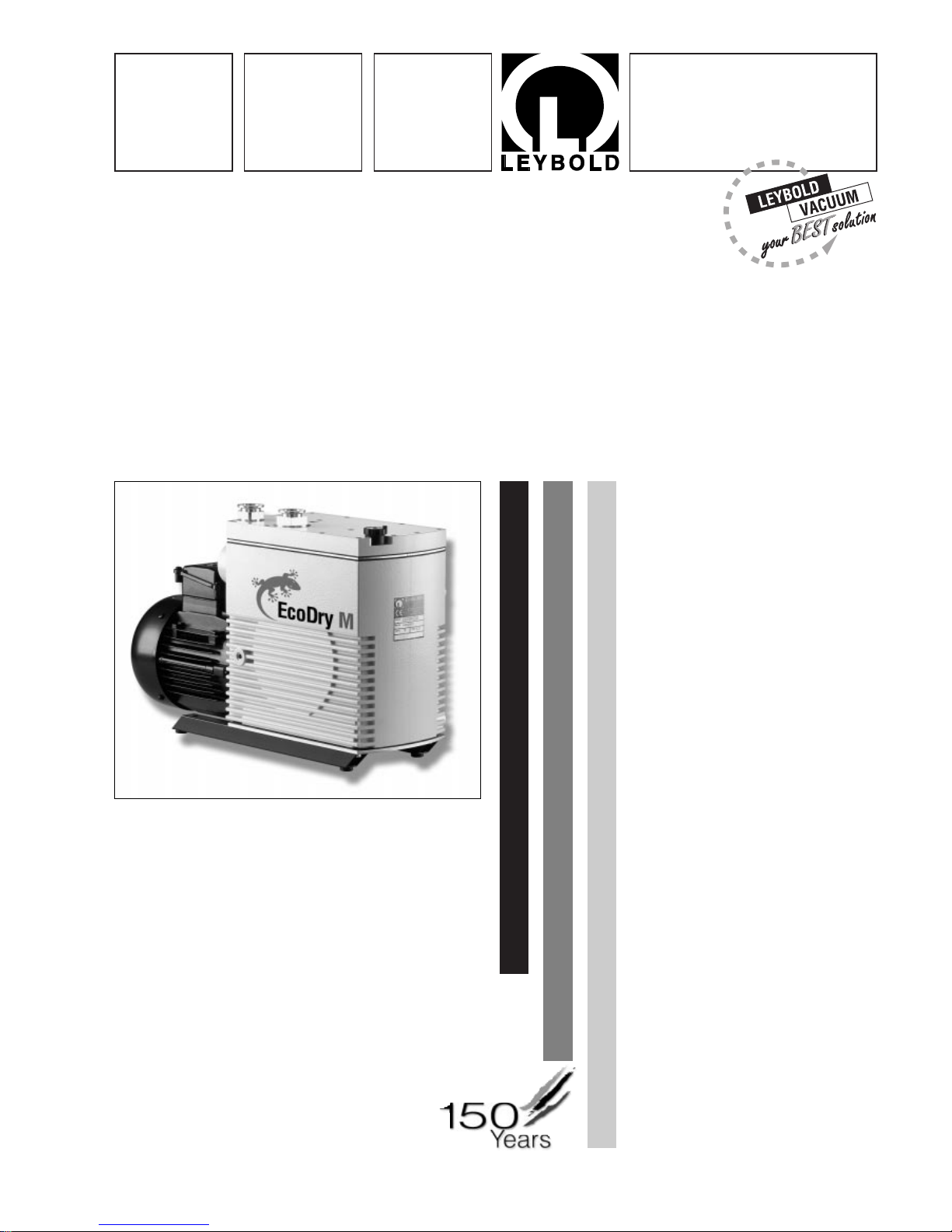
EcoDry - M
Oil-free V acuum Pumps
EcoDry M 15
130 000; 130 001; 130 002; 130 004
EcoDry M 20
130 010; 130 011; 130 012; 130 014
Operating Instructions
GA 01.701/5.02
Vacuum Solutions Application Support Service
LEYBOLD VACUUM
Page 2

GA 01.701/5.02 - 07/01
Contents
2
Contents
Important Safety Considerations . . . . . . . . . . . . . 4
1 Introduction . . . . . . . . . . . . . . . . . . . . . . . . . 6
1.1 Principles of Operation . . . . . . . . . . . . . . . . . 6
1.2 Specifications . . . . . . . . . . . . . . . . . . . . . . . . 7
2 Installation and Operation . . . . . . . . . . . . 10
2.1 Unpacking the Pump . . . . . . . . . . . . . . . . . . 10
2.2 Installation . . . . . . . . . . . . . . . . . . . . . . . . . 10
2.3 Operation of the Pump . . . . . . . . . . . . . . . . 11
2.4 Electrical Connection . . . . . . . . . . . . . . . . . .11
3 Application Notes . . . . . . . . . . . . . . . . . . . 13
3.1 General Application . . . . . . . . . . . . . . . . . . . 13
3.2 EcoDry M Pumps for Backing of
High-Vacuum Pumps . . . . . . . . . . . . . . . . . 13
3.3 Condensable Vapours & Liquids . . . . . . . . . 13
3.4 Use on Wet Processes . . . . . . . . . . . . . . . . 13
4 Maintenance . . . . . . . . . . . . . . . . . . . . . . . .14
5 Troubleshooting . . . . . . . . . . . . . . . . . . . . .15
EC Declaration of Conformity . . . . . . . . . 16
Figures
The references to figures, e.g. (1/2) consist of the Fig.
No.and the Item No. in that order.
Leybold-Service
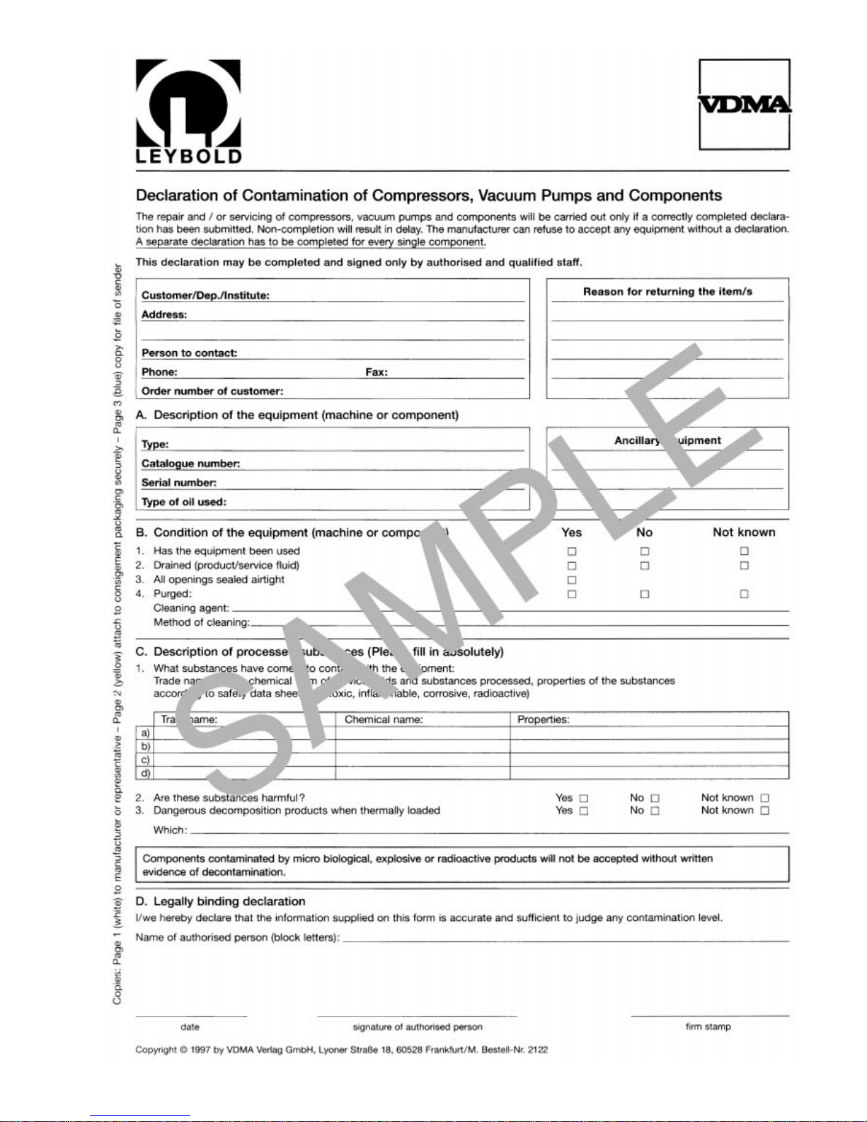
If a pump is returned to Leybold, indicate whether the
pump is free of substances damaging to health or
whether it is contaminated.
If it is contaminated also indicate the nature of the
hazard. Leybold must return any pumps without a
“Declaration of Contamination” to the sender’s address.
Indicates procedures that must be strictly
observed to prevent hazards to persons.
Indicates procedures that must strictly be
observed to prevent damage to, or destruction of the equipment.
Warning
Caution
We reserve the right to modify the design and the specified data.The illustrations are not binding.
Page 3

GA 01.701/5.02 -07/01
3
Ordering Information
ECODRY M 15
with three phase motor Cat. No. 130 000
with single phase motor 115 V 60 Hz USA Cat. No. 130 001
with single phase motor 230 V 50/60 Hz Euro Cat. No.130 002
with single phase motor 200 V 50/60 Hz Cat. No. 130 004
ECODRY M 20
with three phase motor Cat. No. 130 010
with single phase motor 115 V 60 Hz USA Cat. No. 130 011
with single phase motor 230 V 50/60 Hz Euro Cat. No.130 012
with single phase motor 200 V 50/60 Hz Cat. No. 130 014
Accessories
Silencer for
ECODRY M
15 - M 20 Cat. No. 130 050
Vibration absorbers for underneath (Set = 4 pieces) for
ECODRY M
15 - M 20 Cat. No. 130 051
Solenoid gas purge kit for
ECODRY M
15 - M 20 Cat. No. 169 50
Vibration absorber kit for
ECODRY M
15 - M 20 Cat. No. 130 052
Page 4
GA 01.701/5.02 - 07/01
4
IMPORTANT SAFETY CONSIDERATIONS
The Leybold EcoDry M, oil-free vacuum pump is designed for safe and efficient operation when used properly and in
accordance with this manual. It is the responsibility of the user to carefully read and strictly observe all safety precautions described in this section and throughout the manual. This product must be operated and maintained by trained
personnel only. Consult local, state, and national agencies regarding specific requirements and regulations. Address
any further safety, operation and/or maintenance questions to your nearest Leybold Vacuum office.
Warning Failure to observe the following precautions could result in serious personal injury:
• Before beginning with any maintenance or service work on the EcoDry M, disconnect the pump from
all power supplies.
• Do not operate the pump with any of the covers removed. Ser ious injur y may result.
• If exhaust gases must be collected or contained, do not allow the exhaust line to become pressurised.
• Make sure that the gas flow from the exhaust port is not blocked or restricted in any way.
• The standard version of the EcoDry M is not suited for operation in explosion hazard areas. Contact us
before planning to use the pump under such circumstances.
• Before starting up for the first time, the motor circuit (3 phase) must be equipped with a suitable protective motor switch.Please take note of the information in these Operating Instructions or on the electric motor (wiring diagram).
• The EcoDry M is not suited for pumping of:
- combustible and explosive gases or vapours
- radioactive and toxic substances
- pyrophorous substances.
• The EcoDry M must be integrated in the system control arrangement so that the pump can not run-up
automatically after it has been shut down by the temperature switches in the motor. This applies equally to emergency shut-down arrangements. After having determined the fault cause, the pump should
be switched on manually again.
• Avoid exposing any part of the human body to the vacuum.
• Never operate the EcoDry M without a connected intake line or blank flange.
• The location at which the EcoDry M (including its accessories) is operated should be such that angles
over 10° from the vertical are avoided.
• The location of the EcoDry M should be such that all controls are easily accessible.
• Under certain ambient conditions the EcoDry M may attain a temperature of over 80 °C (176 °F).There
then exists the danger of receiving burns.
Note the symbols on the pump pointing to the hazards, and in the case of a hot pump wear the required protective clothing.
• The noise level produced by the EcoDry M without gas ballast is < 59 dB(A) with silencer or connected exhaust line.
Make sure that suitable protection measures are taken to protect the hearing.
• Before operating the EcoDry M with atmospheric gas ballast check first compatibility with the pumped
media so as to avoid hazardous conditions during operation right from the start.
• Before commissioning the EcoDry M, make sure that the media which are to be pumped are compatible with each other so as to avoid hazardous situations.
All relevant safety standards and regulations must be observed.
Warning
Page 5

5
GA 01.701/5.02 -07/01
• It is recommended to always operate the EcoDry M with a suitable exhaust line which is properly
connected. It must slope down and away from the pump.
• When moving the EcoDry M always use the allowed means.
A lifting eye is provided as standard on the pump.
Failure to observe the following precautions could result in damage to the pump:
• Do not allow the ingestion of small objects (screws, nuts, washers, pieces of wire, etc.)
through the inlet port. Always use the screen which is supplied with every pump.
• Do not use the pump for applications that produce abrasive or adhesive powders or
condensable vapours that can leave adhesive or high viscosity deposits. Please contact Leybold Sales
or Service to select a suitable separator.Also please contact Leybold Sales or Service when planning
to pump vapours other than water vapour.
• This pump is suited for pumping water vapour within the specified water vapour tolerance limits.
• Avoid vapours that can condense into liquids upon compression inside the pump, if these substances
exceed the vapour tolerance of the pump (> 25 mbar for water vapour).
• Before pumping vapours, the EcoDry M should have attained its operating temperature, and the gas
ballast should be set to position I - III (position 0 = closed, position 3 = max.water vapour tolerance, 25
mbar).
The pump will have attained its operating temperature about 30 min utes after starting the pump.During
this time the pump should be separated from the process, by a valve in the intake line, for example.
• Be sure that the lines (exhaust and intake lines) and other vacuum connections are clean and free of
oil. This applies in particular if oil sealed pumps were used before. The conditions must be checked
before commissioning, and in the case of deviations you should contact your nearest Leybold Service
office.
• In the case of wet processes we recommend the installation of liquid separators upstream and downstream of the pump as well as the use of the gas ballast.
• The exhaust line should be laid so that it slopes down and away from the pump so as to prevent condensate from backstreaming into the pump.
• In order to prevent the transfer of vibrations from the EcoDry M to other parts of the system we recommend the use of corrugated hoses or compensators on both the intake and the exhaust sides.In case
you need any further information please get in touch with Leybold.
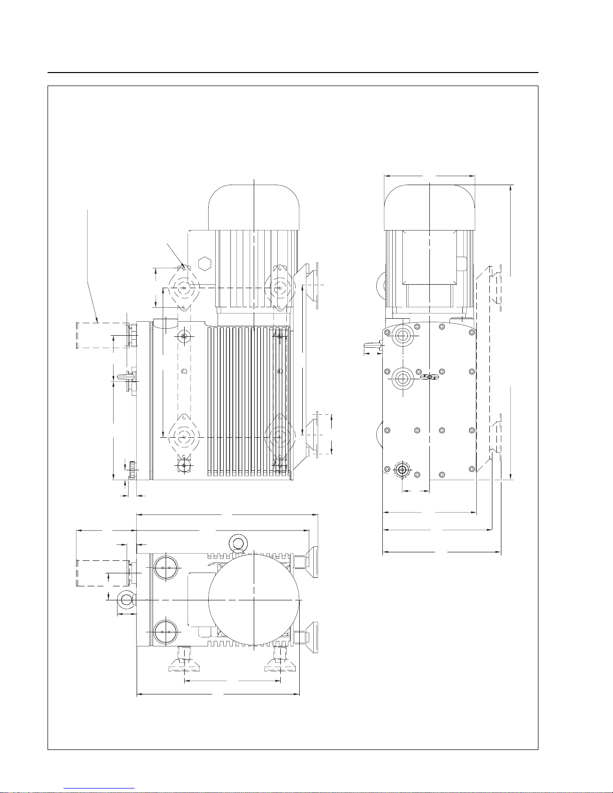
• Operate the EcoDry M only in the orientations detailed in the dimensional drawings (see page 8). For
the purpose of reducing the transfer of vibrations to the building we also recommend the use of vibration absorbers (see accessories for the EcoDry M).
This information will help the operator to obtain the best performance from the equipment:
• Normal amounts of humidity within the range of the pump’s vapour tolerance will not significantly affect
pump performance when the gas ballast is active.
• With the pump switched off, the pressure in the pump will rise very slowly to the level of the exhaust
pressure (normally atmospheric pressure).The EcoDry M is not equipped with any vacuum protection means.Thus you must install a valve in the intake line which automatically seals off the intake port
of the EcoDry M when at standstill.
Caution
Note
Page 6

Introduction
6
GA 01.701/5.02 - 07/01
1 Introduction
EcoDry M pump provides a clean, absolutely oil-free
means of evacuation without the risk of hydrocarbon
contamination. The gas compression stages achieve
pressures as low as 2·10-2mbar (15 mTorr, 2 Pa). The
very low friction coating on the cylinders and on the
pistons allows maintenance-free continuous operation
for up to 2 years depending on the kind of application.
Please note the recommendations as to the applications
provided in these Operating Instructions.
1.1 Principles of Operation
1.1.1 Stages of Compression
The EcoDry M is equipped with three (M 15) or two (M
20) compression stages which are formed by three
pistons.
The gas to be pumped reaches the compression space
of the cylinder by means of slots formed in the walls of
the cylinders.These slots are uncovered by the piston at
bottom dead center and then covered again as the piston
ascends. The gas is compressed while the piston
ascends and exits the compression chamber through
large valves.
1.1.2 Sealing
At initially high pressures, gases may leak past the
piston from the compression chamber and into the driveunit housing (called ”blow-by”). However, the EcoDry M
drive-unit housing is designed such that blow-by gases
are drawn back into the cylinders and exhausted.
Moreover, the entire sealing system of the EcoDry M is
so designed that a low leak rate in the order of
< 1·10-4mbar · l · s-1is attained. The static seals made
of Viton and the PTFE radial shaft seals which are lubricated with a grease which is free of hydrocarbons and
which are highly media compatible, reliably prevent the
exchange of gas between the EcoDry M and the
surrounding atmosphere.
To avoid internal leakage reducing the pump performance, the cylinder and piston are manufactured to very
close tolerances, leaving almost no gap between them.
Additional sealing collars are provided towards the driveunit housing. Towards the outside the chamber of the
shaft is sealed off by a radial shaft seal.
1.1.3 Lubrication
The pistons are covered with a low-friction material.The
low friction coefficient of the PTFE lets it serve as a bearing and seal without additional liquid lubricants.
Moreover, all rolling bearings are lubricated with a grease which is free of hydrocarbons and they are separated
by a dry seal from the vacuum chamber within the pump.
1.1.4 Friction and Cooling
Due to the selection of the pump materials, the friction
(and therefore the heat generated) is kept very low. No
additional cooling is needed in normal applications.
When installing the pump in an enclosure
make sure that there is an adequate flow of
cooling air.
1.1.5 Eliminating Hydrocarbon
Contamination
The risk of contamination by hydrocarbons is a major
concern with mechanical oil-sealed pumps because
liquid lubricants can stream back into the chamber to be
evacuated. The EcoDry M achieves high compression
ratios by using dry multiple-stage compression instead
of oil sealing, and absolutely no liquid lubricants are
used in the compression chambers.
Caution
Page 7
GA 01.701/5.02 -07/01
Specifications
7
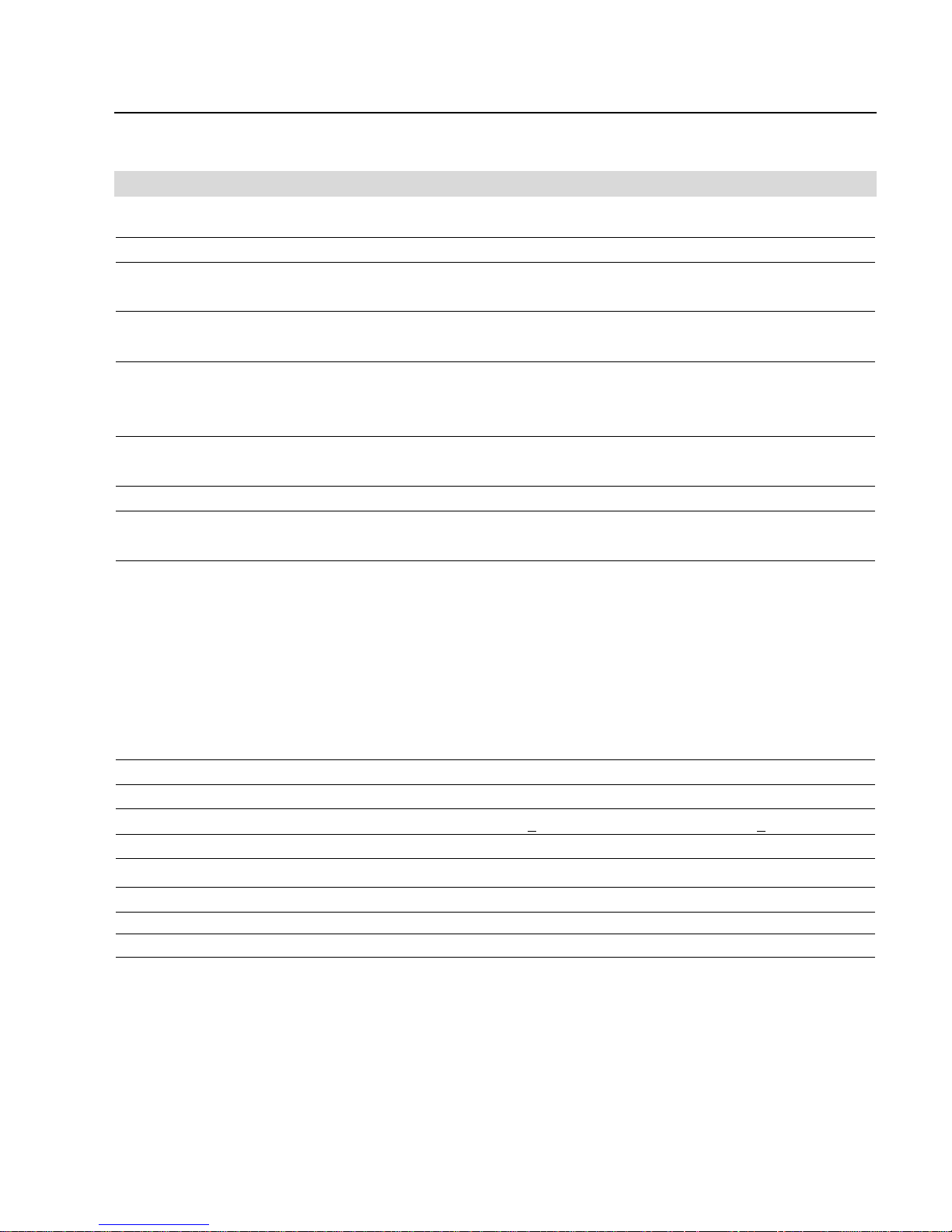
1.2 Specifications
EcoDry M 15 EcoDry M 20
Number of cylinders 3 3
Number of pumping stages 3 2
Max. pumping speed - at 50 Hz m3· h
-1
/ cfm 14/8.3 19/11.2
- at 60 Hz m3· h
-1
/ cfm 16/9.4 22/13
Ultimate pressure - at 50 Hz mbar/Torr 3 · 10-2/ 2.3 · 10
-2
5 · 10-1/ 3.8 · 10
-1
(absolute) - at 60 Hz mbar/Torr 2 · 10-2/ 1.5 · 10
-2
4 · 10-1/ 3.0 · 10
-1
Inlet pressure limit
- at initial evacuation mbar 1000
-
in continuous operation mbar 100
Water vapour tolerance g · h
-1
290 400
(with gas ballast set to “3”) (with gas ballast set to “3”)
Leak rate (integral) mbar·l·s
-1
1·10
-4
1·10
-4
Motor power requirements
at inlet pressures < 20 mbar (15 Torr) W 300 300
Motor
Mains voltage, frequency
3-ph. / 50 Hz V 220-240/346-415 (-10% to +5%) 220-240/346-415 (-10% to +5%)
3-ph. / 60 Hz V 200-277/380-480 (-10% to +5%) 200-277/380-480 (-10% to +5%)
1-ph. 50 / 60 Hz (Euro) V 220 - 240 (-10 % to +5 %) 220 - 240 (-10 % to +5 %)
1-ph. 60 Hz (USA) V 115 (-10 % to +5 %) 115 (-10 % to +5 %)
1-ph 50/60 Hz V 200 (-10 % to +5 %) 200 (-10 % to +5 %)
Motor speed at 50/60 Hz rpm. 1000/1200 1000/1200
Protection IP 54 54
Noise level at ultimate pressure
1)
dB(A) < 59 < 59
Permissible ambient temperature °C/°F 0 - 50 / 32 - 122 0 - 50 / 32 - 122
Connections / Inlet ports DN 25 KF or G 3/4”
Connections /Outlet ports DN 25 KF or G 3/4”
Weight with three phase motor kg/lbs 38/84 38/84
Weight with single phase motor kg/lbs 50/111 50/111
1)
without gas ballast, with silencer (accessory) or connected exhaust line
Page 8
Specifications
8
GA 01.701/5.02 - 07/01
606 max. (545)
1-Phase motor (3-Phase motor)
176
229
212
212
53
37
76
289
76
289
89191
Ø6.2
Exhaust silencer (Option)
Vibration absorber (Option)
19.5
17.2
350
335
117
52
38.7
186
314
20.2
Fig. 1 Dimensional drawing of the EcoDry M with 3-phase motor
Vertical arrangement
Horizontal arrangement
Page 9
Specifications
9
GA 01.701/5.02 -07/01
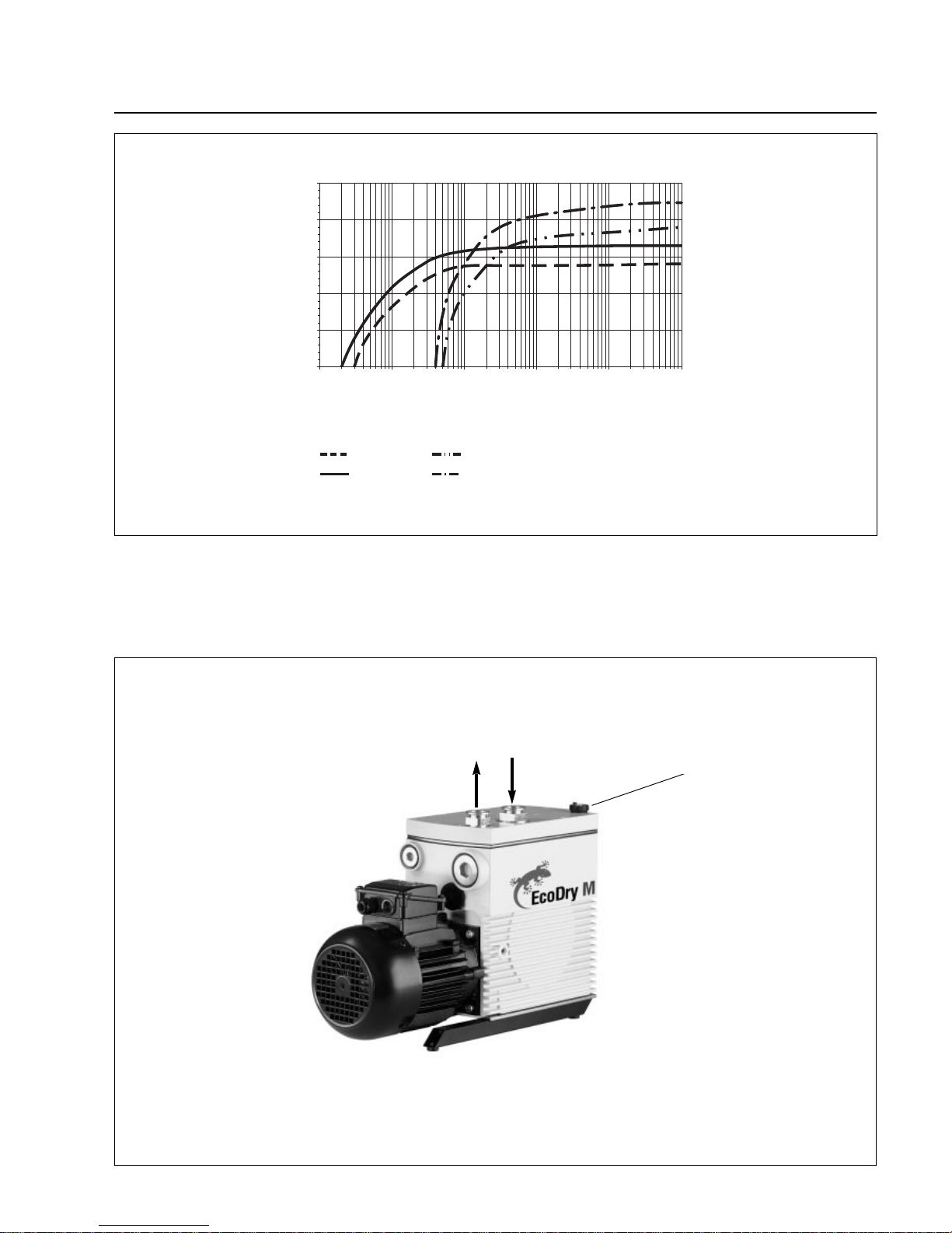
m3/h
mbar
0,01
0
5
10
15
20
25
0,1 1 10
M 15 - 50 Hz
M 15 - 60 Hz
M 20 - 60 Hz
M 20 - 50 Hz
100 1000
Inlet pressure
Pumping speed
Fig. 2 Pumping speed vs. inlet pressure for the EcoDry M 15 / M 20 (50/60 Hz operation)
Fig. 3 Connection for the intake and exhaust flanges
Connecting flanges on top, DN 25 KF
Intake sideExhaust side
Gas ballast valve
Page 10

10
GA 01.701/5.02 - 07/01
2.1 Unpacking the Pump
Leybold Vacuum inspects each EcoDr y M pump before
shipping and packs each pump carefully to avoid damage from improper handling.
2.1.1 Receiving Conditions
Inspect shipping crate for external damage.
If damaged:
• Refuse the shipment.
• Notify Leybold Vacuum immediately.
2.1.2 Unpacking the Pump
1. Open the top of the shipping crate.
2. Remove any packing materials.
3. The pump is equipped with a lifting eye, and should
only be lifted with this device.
2.1.3 Inspecting the Pump
Inspect the pump for damage.
If damaged:
• Notify Leybold Vacuum immediately.
• Retain the original shipping and packing materials.
• Wait for return authorisation from Leybold Vacuum.
• Return the pump in the original package via the
original shipper.
2.1.4 Supplied Equipment
The EcoDry M is supplied with the following basic items:
• Pump with motor
• Separate dirt collecting sieve (dirt trap)
• Operating Instructions
• “Declaration of Contamination” form
The connection ports are sealed off before shipping with
sealing caps.
EcoDry M pumps equipped with a single phase AC
motor have a 1.8 m long mains cord and ma y be connected to the mains direct via the plug.
The AC motors are equipped with a built-in thermal
motor overload circuit breaker and a mains cord (1.8 m
long).
Country specific plugs USA, Japan, Euro are included.In
the case of the three-phase motors suitable motor overload protection and the connection to the mains power
supply must be installed resp.provided by the customer.
2.2 Installation
The EcoDry M pump is installed upright or horizontally
on the anti-vibration mounts provided.
Make sure that there is a clearance of at least 100 mm
to other components or pumps at every side to allow an
adequate air flow for cooling.
The EcoDry M pump is a complete unit. Listed below are
several optional accessories that will lead to more efficient operation and prolong the useful life of the pump.
• Dust filter, liquid separator for the inlet
• Vibration absorbers
• Exhaust silencer
• Inert gas connection
2.2.1 Suggested Installation Procedure
The EcoDry M must only be operated in
such orientations where the axis of the
pump (crankshaft) runs horizontally.
Please accurately observe the following
safety information given in these Operating
Instructions.
1. Install in an open area with an ambient temperature
below 50°C (122 °F). If the pump must be installed in
an enclosed area, air-circulating fans may be necessary to ensure adequate cooling.
2. Before connecting the EcoDry M to the intake and
exhaust lines please remove the shipping seals on the
pump’s intake and exhaust flanges. Connect the
chamber to be evacuated to the inlet flange of the
EcoDry M pump.
3. Use flexible stainless steel bellows in the piping to
reduce transmission of vibrations during operation.
4. Make sure pipe lines are adequately supported to
reduce stress on joints.
5. Install a vacuum gauge in the inlet line with a
vacuum-quality valve upstream of the gauge. This
allows the pump to be isolated from the system to
monitor its proper performance.
2 Installation and Operation
Installation and Operation
Warning
Caution
Page 11
Installation and Operation
11
GA 01.701/5.02 -07/01
6. Install the stainless steel screen (dir t trap) provided
over the inlet port to prevent the ingestion of small
objects that can damage the pump.The flow rate may
be somewhat reduced by the screen, but the protection it provides will prolong the life of the pump.
7. Make sure that the exhaust port is clean and
unobstructed.
Roughing lines and other vacuum connections must be clean, especially if previously
evacuated b y oil-sealed mechanical pumps.
Make sure that the gas flow at the exhaust
port is not blocked or restricted in any way.
If the exhaust gases must be contained or
collected, do not allow the exhaust line to
become pressurised.
2.3 Operation of the Pump
Please note the safety information given on
page 4 and the subsequent pages.
The pump must only be started up after
having fully assembled it.
The exhaust line should be laid so that it
slopes down and away from the pump in
order to prevent condensed vapours from
flowing back into the pump.
During operation, the exhaust side must
always be open. Check any valves which
may be present in the exhaust line.
The max.exhaust backpressure must never
exceed 1200 mbar abs.
2.4 Electrical Connection
Make sure that the mains supply is turned
off when cables are connected.
The electrical connection should only be
performed by staff qualified in accordance
with VDE 0105 and following the guidelines
of VDE 0100.
The EcoDry M pump can be connected to different
mains supply voltages and frequencies (see Section 1.2,
Specifications) as well as page 12.
If necessary, change the jumper configuration in the
motor terminal box (3ph) to adjust the pump to the available supply voltage.
Connect the pump to mains via a suitable protective
motor switch (see name plate), but do not turn on the
pump until all electrical and vacuum lines are connected.
2.4.1 EcoDry M with Single-Phase Motor
The EcoDry M may be connected directly to the mains
supply via the plug.
The cross section of the mains power supply cables should amount to at least 1.5
mm2.
In the case of the single phase AC motors
the direction of rotation is fixed and will therefore not need to be checked separately.
2.4.2 EcoDry M with Three-Phase Motor
Because of the principle of operation employed by the
pump the direction of rotation is not relevant.
If the thermal motor overload circuit breaker
of the pump has responded, the motor will
switch itself on automatically after the temperature has dropped back to permissible
levels.
Caution
Warning
Warning
Warning
Caution
Warning
Page 12
Installation and Operation
12
GA 01.701/5.02 - 07/01
BB
``
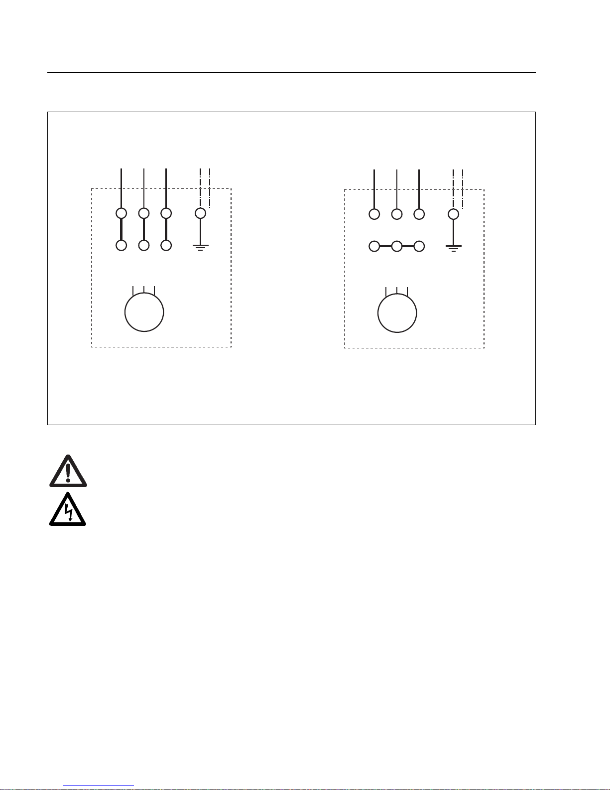
2.4.3 EcoDry - M with 3 phase motor
U1 V1 W1
U2 V2W2
U1 V1 W1
U2 V2W2
M
ää
3
M
ää
3
- Delta circuit - Star circuit
220 - 240 V 50 Hz
200 - 277 V 60 Hz
346 - 415 V 50 Hz
380 - 480 V 60 Hz
Electrical Connection
Before beginning with any electrical work, ensure that the units have been disconnected from the mains
power first.
The electrical connections must only be provided by an electrician in consideration of the requirements
in accordance with DIN EN 60204 Part 1.
The motor must be connected to the mains power as indicated in the drawing.
Before applying the mains power, double check the way in which the wires have been connected to the
terminals.
Fusing must be provided by the customer by means of suitable motor protection switches (Klöckner-Möller PKZMO, for example).
The setting of the motor protection switch must correspond to the current rating stated on the motor’s
name plate.
Warning
Fig. 4 Electrical connections
Page 13

Application Notes
3.3 Condensable V apours &
Liquids
The EcoDry M pump is not suited for prolonged pumping of condensable vapours
above the specified water vapour tolerance.
Pumping of liquids is to be avoided and will
damage the pump.
• Normal amounts of water vapour in atmospheric air
will not affect pump performance.
3.4 Use on Wet Processes
Do not allow direct ingestion of liquids into
the pump.
Note the vapour tolerance levels which
apply to this pump.In case of any questions
in this matter do not hesitate to get in touch
with Leybold Vacuum.
Generally the following applies:
• The lines connected to the pump should be so rated
that no liquids can suddenly enter the pump.
• The chambers should only contain liquids having a
low vapour pressure.
• Note the safety information provided in these
Operating Instructions.
13
GA 01.701/5.02 -07/01
Please also note the information provided
on potential hazards given on pages 4, 5
and the subsequent pages.
3.1 General Application
The EcoDry M is ideal for applications that require the
achievement of pressures as low as 2·10-2mbar
(2 Pa, 15 mTorr ) without the risk of contamination from
liquid lubricants. The pump may be operated intermittently as needed, or continuously for as long as 2 years
without maintenance. Owing to its freedom from hydrocarbons and no compromise in performance, the EcoDry
M replaces single-stage oil-sealed rotary pumps in many
applications.
Do not use the pump for applications that
produce abrasive or adhesive substances
or condensable vapours that can leave
adhesive or high viscosity deposits.
Also the formation of thicker deposits
should be avoided since these too ma y form
adhesive or high viscosity deposits.
3.2 EcoDry M Pumps for
Backing of High-Vacuum
Pumps
3.2.1 Turbopumps and Wide Range Turbo
Pumps
The EcoDry M is an oil-free dry compressing vacuum
pump for safe operation of turbomolecular pumps which
require a forevacuum pressure of p > 2 ·10-2mbar.
The design of the pump permits the EcoDry M to be operated in connection with classic and wide range turbo-
molecular pumps.
3 Application Notes
Caution
Caution
Warning
Caution
Page 14
Maintenance
14
GA 01.701/5.02 - 07/01
4 Maintenance
Under the operating conditions detailed, the EcoDry M is
capable of operating continuously for a period of two
years without any maintenance.
Since no operating means other than electric power are
required for operation of the EcoDry M, any maintenance regarding operating agents and consumption is not
required.
If in spite of this any unexpected maintenance becomes
necessary within this period, please get in touch with the
local Leybold Service.
When returning equipment to our Service please fill in
completely the “Declaration of Contamination” form.
If no such declaration is available to the
Service, any processing will not be possible
and the pump will possibly be returned to
the sender.
The EcoDry M must be packaged in such a
way that the pump can not be damaged
during shipping and so that no hazardous
substances may escape from the package.
Caution
Warning
Page 15

Troubleshooting
15
GA 01.701/5.02 -07/01
5 Troubleshooting
Fault Possible cause Remedy Repair
Pump does not Faulty wiring. Check the wiring and repair it. Electrician
start up. Motor protection switch not set correctly Properly set up the motor protection Electrician
(three-phase motors only). switch.
Power supply voltage does not match Exchange the motor. Service
the rating of the motor.
Motor faulty. Exchange the motor. Service
Pump has seized. Repair the pump. Service
Links in the terminal box. Check the wiring acc. to wir ing diagram. Electrician
Pump does not Method of measurement or measuring Use the right method of measurement
attain its ultimate instrument not suitable. or measuring instrument.
pressure. Measure the pressure directly at
the intake port of the pump.
External leak. Repair the pump. Service
Degassing through water residues. Pump must be run for 30 min in gas
ballast position 1 / check the process.
Process caused strong pollution Disassemble and clean the pump. Service
of the pump.
Defective shaft sealing ring. Change shaft sealing ring. Service
Exhaust pipe dirty. Clean the exhaust pipe and then
run the pump in gas ballast position 1.
Caution:
Roughing lines and other vacuum
lines must be clean. Especially if
previously evacuated by oil-sealed
pumps the lines must be cleaned first.
Exhaust pressure too high Optimise cross section of the
(Pabs =>1200 mbar). exhaust pipe.
Pump temperature too low. Warm up the pump (>1h).
Pumping speed of Dirt trap in the intake line is clogged. Clean the dirt trap.
the pump is too Connection lines too narrow or too long. Use sufficiently wide and short intake
low. lines.
(see application information).
Preventive action::Install a dust filter in the intake line.
Exchange the filter element.
Exhaust counter-pressure too high. Optimise cross section of the
exhaust pipe.
Nom. pumping speed of pump is too low. Check the application.
After switching the System has a leak. Check the system.
pump off, the Missing valve for blocking intake Fit a valve that seals off the inlet
pressure in the (automatic or at pump standstill). (see application information).
system increases Valve at the intake is not closed. Close the valve for inlet.
too fast. Exhaust valve leaky (loud noise from the Repair the pump. Service
exhaust system at ultimate pressure).
Pump gets hotter Supply of cooling air is obstructed. Install the pump properly (10 cm
than previously clearance around the pump).
observed. Ambient temperature is too high. Install the pump properly (<50°C).
Process gas is too hot. Change the process, if needed cool
down to max. inlet temperature = 50°C.
Deviation of the mains voltage. Check the motor-supply voltage Electrician
and mains voltage.
Exhaust pressure too high. Optimise cross sectional area
exhaust pipe.
The pump is Faulty bearing. Repair the pump. Service
extremely loud. Thick particulate deposits. Repair the pump. Service
Silencer defective. Repair silencer.
High gas throughput with open Install exhaust line or a silencer
exhaust port.
Page 16

16
GA 01.701/5.02 - 07/01
We – LEYBOLD VACUUM GmbH – herewith declare
that the products defined below meet the basic requirements regarding safety and health of the relevant EC
directives by design, type and the versions which are
brought in to circulation by us.
In case of any products changes made without our
approval, this declaration will be void.
Product designation: Oil-free vacuum pump
Models: Cat. No.
EcoDry - M 15 130 000
130 001
130 002
130 004
EcoDry - M 20 130 010
130 011
130 012
130 014
EC Declaration of Conformity
The product meets the requirements of the following
directives:
• EC Directive on Machinery (98/37/EG)
• EC Directive on Low-Voltages (73/23)+(93/68/EWG)
• EC Directive on Electromagnetic Compatibility
(89/336/EWG)
(91/263/EWG) + (92/31/EWG) + (93/68/EWG)
Applied harmonised standards:
• DIN EN 292 Part 1 11.91
• DIN EN 292 Part 2 06.95
• DIN EN 1012 Part 2 07.96
• DIN EN 60 204 Part 1 11.98
Applied national standards and technical
specifications:
• DIN 31 001 Apr il 1983
Cologne, July 02, 2001
—————————————————————
K. Kilian, Business Area Manager LPV
Division Industrial
Cologne, July 02, 2001
—————————————————————
Dr.Bahnen, Head of R&D LPV
Division Industrial
Page 17
17
GA 01.701/5.02 -07/01
Page 18

GA 01.701/5.02 - 07/01
LPV_03830_2001 bicom/OF 07.01
Printed in Germany on chlorine-free bleached paper
LEYBOLD V AKUUM GmbH
Bonner Strasse 498 (Bayenthal)
D-50968 Cologne
Tel.: ++49 (0)221 347-0
Fax: ++49 (0)221 347-1250
http://www.leyboldvac.de
e-mail:[email protected]
USA:
LEYBOLD VA CUUM USA
5700 Mellon Road
Export, PA 15632
Phone: +1-724-327 57 00
Fax: +1-724-733 12 17
Internet:http://www.
leyboldvacuum.com
Canada:
LEYBOLD Canada Inc.
7050 Telford Way, Unit 5
Mississauga, Ontario
Canada L5S 1V7
Phone: +1-905-672 77 04
Fax: +1-905-672 22 49
e-mail:
[email protected]
AMERICA EUROPE ASIA
Deutschland:
LEYBOLD VAKUUM
GmbH
Bonner Straße 498
D-50968 Köln
Phone: +49-221-347-1234
Fax: +49-221-347-12 45
Internet: www.leyboldvac.
de
e-mail:
sales
@
leybold
vakuum.com
Belgien/Niederlande/
Luxemburg:
LEYBOLD N.V.
Leuvensesteenweg 542, 9A
B-1930
Zaventem
Phone: +32-2-71 10 083
Fax: +32-2-72 08 338
LEYBOLD B.V.
Computerweg 7
NL-3606 AV Maarssen
Phone: +31-346-583 999
Fax: +31-346-583 990
Frankreich:
LEYBOLD S.A.
7, Avenue du Quebec
Z.A. de Courtaboeuf, B.P. 42
F-91942
Courtaboeuf
Cedex
Phone: +33-1-6982 48 00
Fax: +33-1-69 07 57 38
e-mail:
Compuserve:100635,43
Groß-Britannien/Irland:
LEYBOLD LTD.
Waterside Wa y,
Plough Lane
GB-London SW 17 OHB
Phone: +44-208-9717000
Fax: +44-208-9717001
Italien:
LEYBOLD S.P.A.
Via T r asimeno 8
I-20128 Milano
Phone: +39-02-27 22 31
Fax: +39-02-27 20 96 41
Spanien:
LEYBOLD S.A.
C/. Mataró, 27
Polígono Industrial Les
Grases
E-08980 Sant Feliu de
Llobregat (Barcelona)
Phone: +34-93-666 46 16
Fax: +34-93-666 43 70
Schweden:
LEYBOLD AB
Box 9084
40092 Göteborg
Phone: +46-31-68 84 70
Fax: +46-31-68 39 39
Schweiz/
Liechtenstein:
LEYBOLD AG
Leutschenbachstraße 55
CH-8050 Zürich
Phone: +41-1-308 40 50
Fax: +41-1-302 43 73
Volksrepublik China:
LEYBOLD (Tianjin)
VACUUM EQUIPMENT
MANUFACTURING Co.,
Ltd.
Beichen Economic Development Area (BEDA)
Tianjin 300400, China
Phone: +86-22 26 972 016
Fax: +86-22 26 972 017
e-mail:
Japan:
LEYBOLD Co., Ltd.
Head Office
Tobu A.K. Bldg. 4th Floor
23-3, Shin-Yokohama 3chome
Kohoku-ku,Yokohama-shi
Kanagawa ken 222-0033
Phone: +81-45-471 33 30
Fax: +81-45-471 33 23
Korea:
LEYBOLD Korea Ltd.
4th Fl. Shinan Bldg., 173-1
Jangchoog-dong 2ga,
Choong-ku
Seoul 100-392, Korea
C.P.O. Box 709
Phone: +82-2-227 11 567
Fax: +82-2-227 11 568
Singapore:
BALZERS and LEYBOLD
Singapore Pte. Ltd.
1 Tuas South Street 3
Singapore 638043
Phone: +65-865 18 65
Fax: +65-862 22 95
Taiwan:
LEYBOLD T aiw an, Ltd.
2 F, No 416-1, Sec. 3
Chung-Hsin Rd.
Chu T ung, Hsinchu.
Taiwan R.O.C: 310
Phone: +886-3-583 39 88
Fax: +886-3-583 39 99
Sales Net worldwide
 Loading...