

Lexycom Technologies TIAMIS-800 User Manual

TIAMIS-800 wireless radio transceiver
User Manual
Lexycom Technologies, Inc.
1227 Reserve Dr.
Longmont, CO 80501
info@lexycominc.com
March 2006, Ver. 1.3a

TIAMIS-800 wireless radio transceiver
User Manual. Ver. 1.3
Table of Contents
Table of Contents .............................................................................................................2
Revision history.................................................................................................................. 3
Notice.................................................................................................................................. 3
General Safety Information................................................................................................. 4
Electro Static Discharge (ESD) .......................................................................................... 4
FCC Notifications...............................................................................................................5
Electronic FCC ID .............................................................................................................. 6
1. Introduction..................................................................................................................... 8
2. Quick Start...................................................................................................................... 8
3. Operating Modes........................................................................................................... 10
3.1. Description of the messages in the network .......................................................... 10
3.2. Point-to-Point network overview........................................................................... 10
3.2.1. Functionality of the Point-to-Point Master (P2P Master)............................... 10
3.2.2. Functionality of the Slave in a Point-to-Point network .................................. 11
3.3. Point-to-Multipoint network overview.................................................................. 12
3.3.1. Functionality of the Point-to-Multipoint Master (P2M Master)..................... 12
3.3.2. Functionality of the Slave in a Point-to-Multipoint network.......................... 13
3.4. TDMA network overview...................................................................................... 14
3.4.1. Choosing between TDMA and Point-to-Multipoint networks....................... 14
3.4.2. Functionality of the TDMA Master................................................................15
3.4.3. Functionality of the Slave in a TDMA network ............................................. 16
4. Data Interfaces supported ............................................................................................. 18
4.1. Functionality of the transceiver’s RS232 input and output buffers....................... 20
4.2. CTS line timing...................................................................................................... 20
5. Transceiver’s LEDs ...................................................................................................... 22
6. Frame Table.................................................................................................................. 26
7. Diagnostics.................................................................................................................... 29
8. Technical Support......................................................................................................... 31
9. Return Authorization and Shipping Information..........................................................31
10. Warranty ..................................................................................................................... 31
Appendix A. Settings used by the transceiver.................................................................. 32
Information in this document is subject to change without notice.
© 2005 Lexycom Technologies, Inc. All rights reserved.
Microsoft and Windows are registered trademarks of the Microsoft Corporation.
Other product names mentioned in this manual may be copyrights, trademarks, or registered
trademarks of their respective companies and are hereby acknowledged.
The Tiamis-800 Wireless Data Transceiver is made in the United States of America.
Printed in the United States of America.

TIAMIS-800 wireless radio transceiver
User Manual. Ver. 1.3a
Revision history
Revision Released Firmware level covered
1.0 November, 2005 1.06e and prior
1.2 February, 2006 1106.i and prior
1.3 March, 2006 1106.i and prior
1.3a May, 2006 1106Mi and prior
Notice
Changes or modifications not expressly approved by Lexycom Technologies, Inc. could
void the user’s authority to operate this equipment.
Any and all product information in this document is subject to change without notice.

TIAMIS-800 wireless radio transceiver
User Manual. Ver. 1.3a
General Safety Information
Lexycom Technologies, Inc. does not recommend the use of its products in life support
applications where the failure or malfunction of a component may directly threaten life or
lead to an injury.
Do not operate radio equipment near electrical blasting caps or in an explosive
atmosphere.
Do not operate radio transmitter unless all RF connectors are secure and any open
connectors are properly terminated.
Do not allow the antenna to come close to, or touch, the eyes, face, or any exposed body
parts while the radio is transmitting.
Be sure that your Tiamis-800 transceiver has been provided with sufficient DC voltage
and current.
All equipment should be installed according to the manufacturer’s instructions and in
accordance with all regulatory agencies.
Electro Static Discharge (ESD)
Static build up can cause serious damage to electronic devices when improperly handled.
Appropriate precautions should be taken when handling the transceiver(s).

TIAMIS-800 wireless radio transceiver
User Manual. Ver. 1.3a
FCC Notifications
This device complies with part 15 of the FCC Rules. Operation is subject to the following
two conditions: 1) This device may not cause harmful interference and 2) this device
must accept any interference received, including interference that may cause undesired
operation.
This device must be operated as supplied by Lexycom Technologies, Inc. Any changes or
modifications made to the device without the express written approval of Lexycom
Technologies may void the user's authority to operate the device.
NOTE: The Tiamis-800 transceivers are sold to be professionally installed only.
WARNING: The Tiamis-800 transceiver has the maximum transmitted output power of
1 Watt. It is required that the transmit antenna be kept at least 23 cm away
from nearby persons to satisfy FCC RF exposure requirements.
WHEN INSTALLED INSIDE OF ANOTHER DEVICE: The Tiamis-800 is a
modular transmitter. Therefore, in accordance with the FCC rules, when
installed inside of another device, the outside of this device must display a
label referring to the enclosed module. This exterior label can use wording
such as “Contains FCC ID: TKY-TMS800”. Any similar wording that
expresses the same meaning may be used.
NOTE: This equipment has been tested and found to comply with the limits for a
Class A digital device, pursuant to part 15 of the FCC Rules. These limits
are designed to provide reasonable protection against harmful interference
in the commercial installations. This equipment generates, uses and can
radiate radio frequency energy and, if not installed and used in accordance
with the instructions, may cause harmful interference to radio
communications. Operation of this equipment in a residential area is likely
to cause harmful interference in which case the user will be required to
correct the interference at his own expense.
TIAMIS-800 wireless radio transceiver
User Manual. Ver. 1.3a
Electronic FCC ID
The Tiamis-800 transceiver is a Software Defined Radio transceiver (SDR). Its FCC ID
label can be accessed by using a standard terminal program such as Hyper Terminal or
similar.
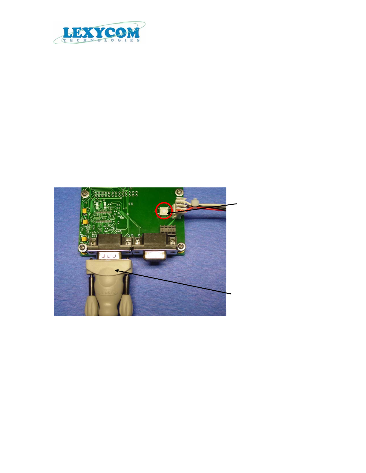
To access transceiver’s FCC ID, follow the steps below.
1. Connect one end of the data cable supplied to you by Lexycom to the RS232
diagnostics connector and the other end of the same cable to the programming
computer’s COM port.
Setup switch
Data cable is connected to
the RS232 diagnostics port.
2. Apply power to the transceiver by turning the power source On.
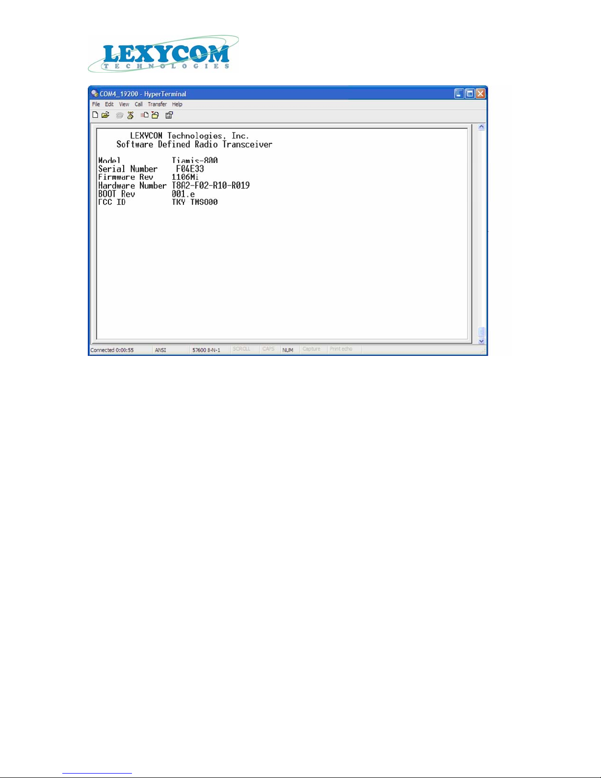
3. On the computer, start the Hyper Terminal or similar terminal program.
4. Push the Reset button on the interface board. The Hyper Terminal’s screen will show
FCC ID number (shown below).
TIAMIS-800 wireless radio transceiver
User Manual. Ver. 1.3a

TIAMIS-800 wireless radio transceiver
User Manual. Ver. 1.3a
1. Introduction
The Tiamis-800 is a software-defined radio transceiver. When loaded with firmware
1106.i and prior, it supports frequency hopping spread spectrum operation in the 902-928
MHz license free frequency band.
The Tiamis-800 provides the end user with a flexible, reliable, secure data
communication solution. With its fast frequency hopping capability the Tiamis-800 easily
avoids interference even in the most complex environments.
The Tiamis-800 transceiver is aimed to be used in applications such as remote data
gathering and control, GPS based networks, SCADA systems, remote monitoring, and as
a wireless bridge.
2. Quick Start
When purchased, the Lexycom wireless data transceivers are shipped from the factory
pre-configured to operate in the Slave mode of operation with the acknowledgement
turned off. The settings, however, can be changed by the user at any time by using
“Configuration Program” supplied with the transceivers.
Using the same program, if needed, the settings on the transceivers can be changed back
to the factory default.
The transceiver’s data port is preset for RS232 baud rate of 115.2 kb/s. Its diagnostics
port is set to operate at 57.6 kb/s (fixed settings, cannot be changed by the user).
When used for RS232 data transfers, the transceiver functions as a null modem cable.
Therefore, if the Tiamis-800 is to be used to replace a straight-through RS232
connection, then a null modem cable must be placed between the transceiver and the
DCE instrument to which it is connected.
To establish communications between a pair of Lexycom Wireless Data Transceivers just
received from the factory:
1. Set the RS232 baud rate on each transceiver to match the baud rate of the instrument to
which it is connected. Please note that the baud rate settings do not have to be the same
on each transceiver in the network.
DOUM0003AA Page 8 of 35

TIAMIS-800 wireless radio transceiver
User Manual. Ver. 1.3
2. Connect one side of the RS232 cable supplied from the factory to the data port of the
transceiver. Connect the other end of this cable to your instrument.
3. Connect an antenna to the transceiver’s RF connector.
4. Configure the transceiver to operate in the Master mode if necessary.
5. Make sure your power source is capable of supplying a DC voltage in the range
between 4.5 and 25 VDC. Also, confirm that your power source is capable of delivering
at least 6.5 Watts of power to the transceiver.
6. Connect the power cord from your power source to the transceiver.
7. Turn On your power source.
8. Repeat all of the steps above with the rest of the transceivers, which will be a part of
the same network.
9. Shortly after all modems are plugged in they should establish a communications link
with each other and your connection is complete!
DOUM0003AA Page 9 of 35

TIAMIS-800 wireless radio transceiver
User Manual. Ver. 1.3
3. Operating Modes
The version of the firmware 1106.i and prior supports the following network topologies:
• Point-to-Point,
• Point-to-Multipoint,
• TDMA.
3.1. Description of the messages in the network
Generally, there are two types of RF channel messages/packets supported by the
transceiver:
• Global_Packet. Means that the packet is sent to all listening transceivers in the
network. If a transceiver hears a Global_Packet and if the packet reception was
error-free, then the data portion of such packet (if exists) will be sampled out by
the transceiver to its data port.
• Local_Packet. Means that the packet is sent to a specific transceiver in the
network. In the case of a good packet reception, only the addressed transceiver
will deliver the data portion of such packet (if exists) to its data port.
3.2. Point-to-Point network overview
In general, a Point-to-Point network includes a Point-to-Point Master (P2P Master), a
Slave, and optional Repeater(s). The network allows two way communications between
the P2P Master and the Slave.
The typical Point-to-Point network assumes that all of the messages sent between P2P
Master and the Slave required acknowledgement by the receiving site. However, the user
can turn the acknowledgement On or Off for one of the radios or for both. It gives added
flexibility to the user to adjust the network performance to the application requirements.
All of the packets sent within Point-to-Point network are always Local_Packets addressed
either to the P2P Master or to the Slave.
3.2.1. Functionality of the Point-to-Point Master (P2P Master)
A P2P Master radio can send a new packet of data over the RF channel only if the link to
the Slave is On.
DOUM0003AA Page 10 of 35

TIAMIS-800 wireless radio transceiver
User Manual. Ver. 1.3
Each RF packet, which the P2P Master sends out, is addressed to a specific Slave and
sent as a Local_Packet.
There are several Master settings, which must be considered when setting up the Slave
radio to operate in the same network. Below are the Master’s settings, which need to be
matched by the recipient Slave radio in the network:
• The Slave must have its Recipient_UnitID matching the Master’s my_UnitID.
• The Slave must have its NetworkID and their AddressMask matching the
corresponding Master’s settings.
• Selected Master’s hopping pattern, HopTableLength, and the options selected for
each of the hopping channels must be repeated on the Slave unit.
The settings ignored by the Master radio:.
• BytesThreshold.
• FrameToWait.
3.2.2. Functionality of the Slave in a Point-to-Point network
A Slave radio can send a new packet of data over the RF channel only if the following
conditions are met:
• The link is On.
• The number of bytes in the Slave’s input buffer is greater than or equal to the
BytesThreshold settings OR if the Slave did not send RF packets for longer than
FramesToWait number of frames and its input buffer has at least one byte of the
user’s data in it.
• The last packet it received from the Master was Global_Packet or Local_Packet
addressed to this Slave.
The Slave transceiver will send each RF packet once and will repeat it PacketRepeat
times. Therefore, when used in Point-to-Point network configuration, the PacketRepeat
settings must be set to ‘0’.
The Slave will loose a link to the Master if it does not hear the Master’s transmissions for
TimeoutRetries consecutive frames. Once the link is lost, the Slave will start searching
for the Master.
The Slave can link to the P2P Master only if it hears the Master’s transmission and only
if the Master is transmitting Local_Packet(s) addressed to this Slave.
The Slave’s settings, which need to match the Master’s settings in the order for the
Slave to be able to operate in the network:
• Each Slave in the network must have its Recipient_UnitID matching the Master’s
my_UnitID.
DOUM0003AA Page 11 of 35
 Loading...