

Lexus Electronic Weighing AXIS ATA Series, ATZ2200, AXIS ATZ Series, ATZ220, ATZ520 User Manual
ATZ2200
ATZ220÷ATZ520
USER MANUAL
AXIS ATA and AXIS ATZ Series
Ver. 1 2014-08

2
USER MANUAL
___
_ _ _ _ _ _ _ _ _ _ _ _ _ _ _ _ _ _
_____
_ _ _ _ _ _ _ _ _ _ _ _ _ _ _ _
Contents:
1. General description............................................................................................... ....................................................... 3
2. Completeness ............................................................................................................................................................. 3
3. Safety rules......................................................................................................................................................................................................................................................................................................................... 4
4. Technical data ............................................................................................................................................................. 5
5. General scale view ...................................................................................................................................................... 6
6. Keys and indicators.............................................................................................................................................................................................................. 8
7. Preparing working environment ............................................................................................................................... ..... 9
8. Preparing scale to work ............................................................................................................................................. 10
9. General operation principles ...................................................................................................................................... 11
10. Start-up .................................................................................................................................................................... . 12
11. Internal calibration............................................................................................... ...................................................... 13
12. Checking the balance ................................................................................................................................................ 14
13. Connection with computer or a printer ........................................................................................................................ 15
14. Basic scale functions ............................................................................................... .................................................. 19
14.1. Simple weighing ........................................................................................................................................................ 19
14.2. Weighing with tare ............................................................................................... ...................................................... 19
15. Special functions ............................................................................................................................. .......................... 20
15.1. Customization of special functions menu (ACtIV and dEFAULt) .................................................................................. 21
15.2. Autozeroing function (AutotAr) ............................................................................................................................... .... 22
15.3. Pieces counting function (PCS) .................................................................................................................................. 23
15.4. Function for changing mass unit (UnIt) ............................................................................................... ........................ 24
15.5. Percent calculation functions (PErCEnt) ..................................................................................................................... 25
15.6. Function for summing recipe ingredients (rECIPE) ...................................................................................................... 26
15.7. Calibration with external weight / calibration options (CALIbr)...................................................................................... 27
15.8. Label choosing function (LAbEL)............................................................................................................................. ... 31
15.9. Function for setting serial interface parameter (SErIAL) ............................................................................................. . 32
15.10. Printout configuration (PrInt)........................................................................................................................... .... 33
15.11. Animal weighting function (LOC) ........................................................................................................................ 35
15.12. Memorizing tare function (tArE) .......................................................................................................................... 36
15.13. Maximum value indication function (UP) ............................................................................................................ . 37
15.14. Force measuring function (nEWton) ................................................................................................................... 38
15.15. Anty-disturbance filter option (FILtEr).................................................................................................................. 38
15.16. Setting backlight function (b_LIGHt) ................................................................................................................... 39
15.17. Function for choosing reading unit (rESOLUt) ..................................................................................................... 39
15.18. Statistical calculations function (StAt) ................................................................................................................. 40
15.19. Basis weight of paper counting function (PAPEr) ................................................................................................ 43
15.20 Density determination (dEnSity) ......................................................................................................................... 44
15.20.1 Solids density determination........................................................................................................................... 44
15.20.2 Liquid density determination............................................................................................... ............................ 46
15.21. Total weight function (totAL)............................................................................................................................. .. 47
15.22. Date and time setting (dAtE) ............................................................................................................................. . 49
15.23. Function of comparing with preset threshold values (thr) ..................................................................................... 50
15.24 Firmware (FIrMW).............................................................................................................................................. 53
16. Troubleshooting and maintenance ............................................................................................... .............................. 53
Declaration of Conformity............................................................................................... ..................................................... 54
ATA firmware diagram ............................................................................................................................. ........................... 55

3
USER MANUAL
___
_ _ _ _ _ _ _ _ _ _ _ _ _ _ _ _ _ _ _
__
_ _ _ _ _ _ _ _ _ _ _ _ _ _ _ _
1. General description
ATA i ATZ series electronic scales are destined for laboratory works which require
high accuracy and for wide range of technical purposes as well. ATZ series are not
equipped with internal calibration system.
All scales are metrologically tested by manufacturer.
All balances can be prepared to comply with verification requirements but legally
verification is not possible yet.
According to an order balances can be calibrated.
NACE classification: 33.20.31.
2. Completeness
Standard set consists of:
1. Scale
2. Feeder
3. Draft shield with cover,
4. User manual
5. Guarantee card

4
USER MANUAL
___
_ _ _ _ _ _ _ _ _ _ _ _ _ _ _ _ _ _
_____
_ _ _ _ _ _ _ _ _ _ _ _ _ _ _ _
3. Safety rules
It is necessary to follow safety rules of work with the scale
shown below. Obeying those rules is the condition to
avoid electrical shock or damage of the scale or
connected peripheral devices.
All repairs and necessary regulations can be made by authorised personnel
only.
To avoid fire risk use a feeder of an appropriate type (if feeder is supplied
with the scale) and supply voltage has to be compatible with specified
technical data.
Do not use the scale when its cover is opened.
Do not use the scale in explosive conditions.
Do not use the scale in high humidity environment.
If the scale seems not to operate properly, switch it off and do not use until
checked by authorised service.
According to current acts of low about protection of
natural environment, wasted scales should not be put into
waste containers together with ordinary waste.
Wasted scale after operation period can be delivered to units authorized for
gathering wasted electronic devices or to the place where it was bought.
5
USER MANUAL
___
_ _ _ _ _ _ _ _ _ _ _ _ _ _ _ _ _ _ _
__
_ _ _ _ _ _ _ _ _ _ _ _ _ _ _ _
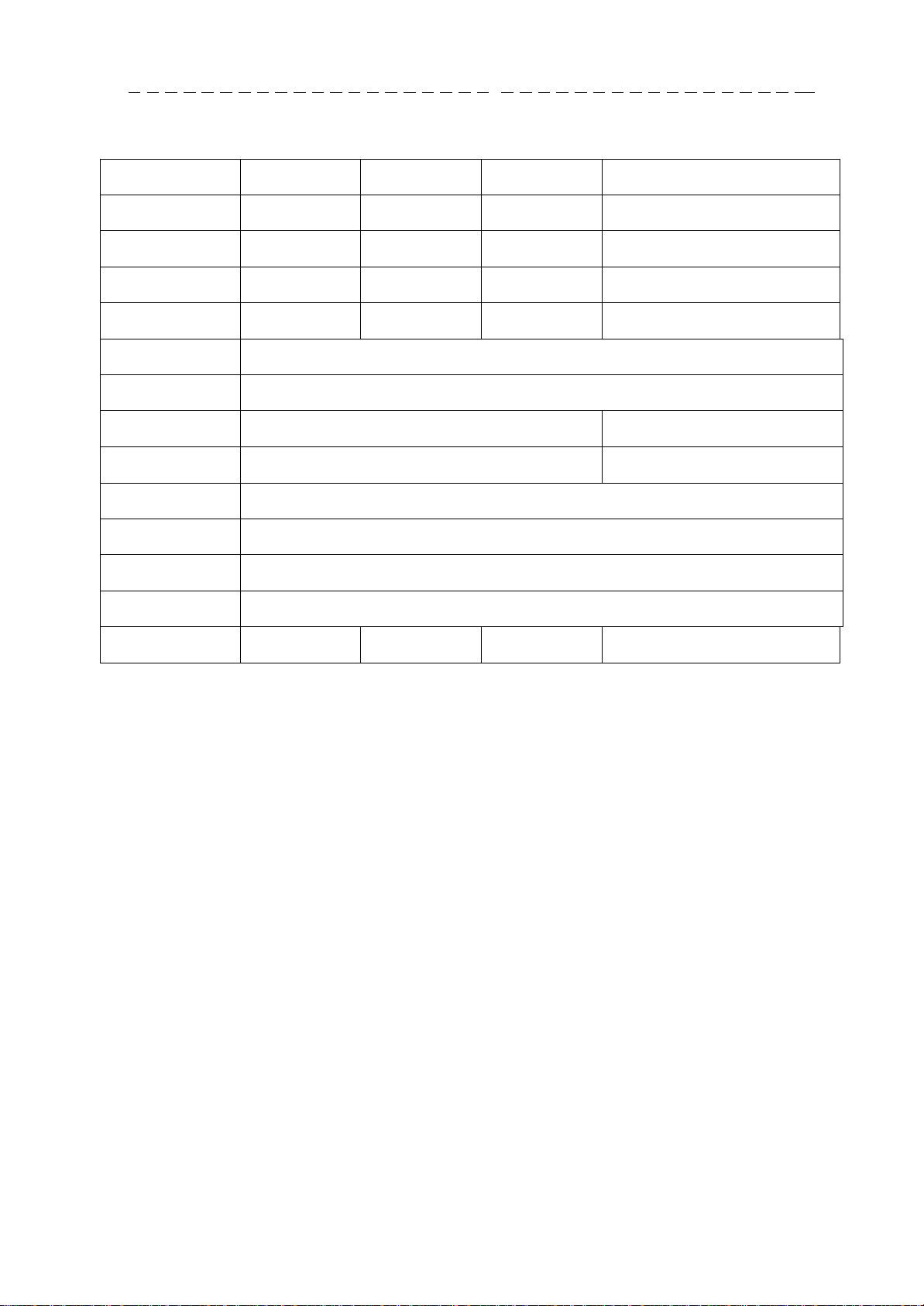
Type
ATZ320
ATZ520
ATZ1200
ATZ2200
Load (Max)
320g
520g
1200g 2200g
Readout unit (d)
0,001g
0,001g
0,01g 0,01g
Verification plot
(e)
0,01g
0,01g
0,1g 0,1g
Tare range
-320g
-520g
-1200g
-2200g
Accuracy class
II
Working
temperature
+18 ÷ +33°C
Weighing time
< 3s
< 2s
Pan dimension
Ø115mm
Ø150mm
Dimensions
185x290x90mm
Interfaces
In standard: RS232C and USB
Supply
~230V 50Hz 6VA / =12V 1,2A
Scale weight
ATA : 2,6kg ATZ: 2,1kg
Recommended
standard of mass
F2 200g
F1 500g
F2 1000g
F2 2000g
4. Technical data
Note:
F2 and F1 are names of international calibration weight classes according to O.I.M.L.
Requirements about calibration weight accuracy are connected with these classes.

6
USER MANUAL
___
_ _ _ _ _ _ _ _ _ _ _ _ _ _ _ _ _ _
_____
_ _ _ _ _ _ _ _ _ _ _ _ _ _ _ _
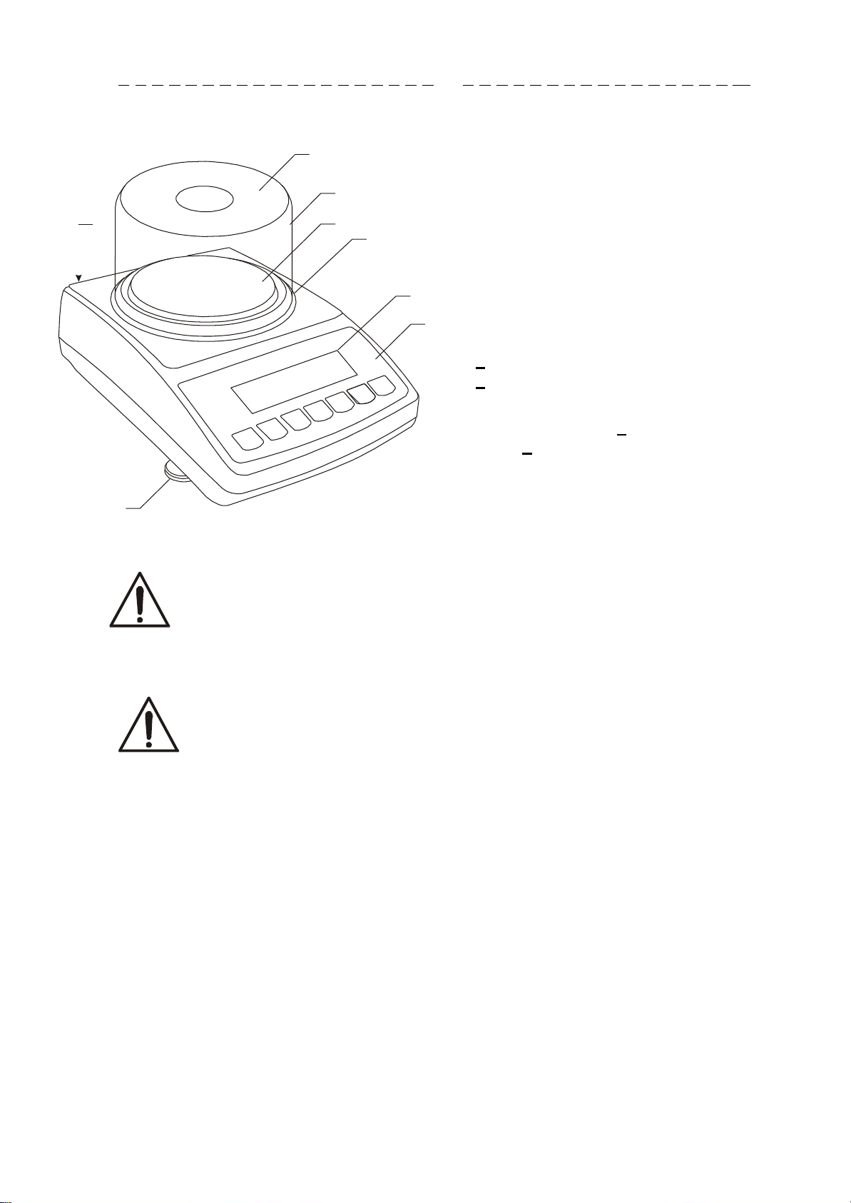
5. General scale view
ATA120÷ATA520 and ATZ120÷ATZ520 scale:
9
8
7
1
2
3
6
ATA1200÷ATA2200 and ATZ1200÷ATZ2200 scale:
1
7
2
6
1 – pan
2 – pan support
(under pan)
3 – pan ring
(against blows)
4 – display LCD
5 – keys
6 – rotating legs
4
5
7 – water level
8 – draft shield
(option)
9 – draft shield cover
(option)
1 – pan
2 – pan support
4
5
3 – information window
4 – display LCD
5 – keys
6 – rotating legs
7 – level
7
USER MANUAL
___
_ _ _ _ _ _ _ _ _ _ _ _ _ _ _ _ _ _ _
__
_ _ _ _ _ _ _ _ _ _ _ _ _ _ _ _
1
2
3
4
5
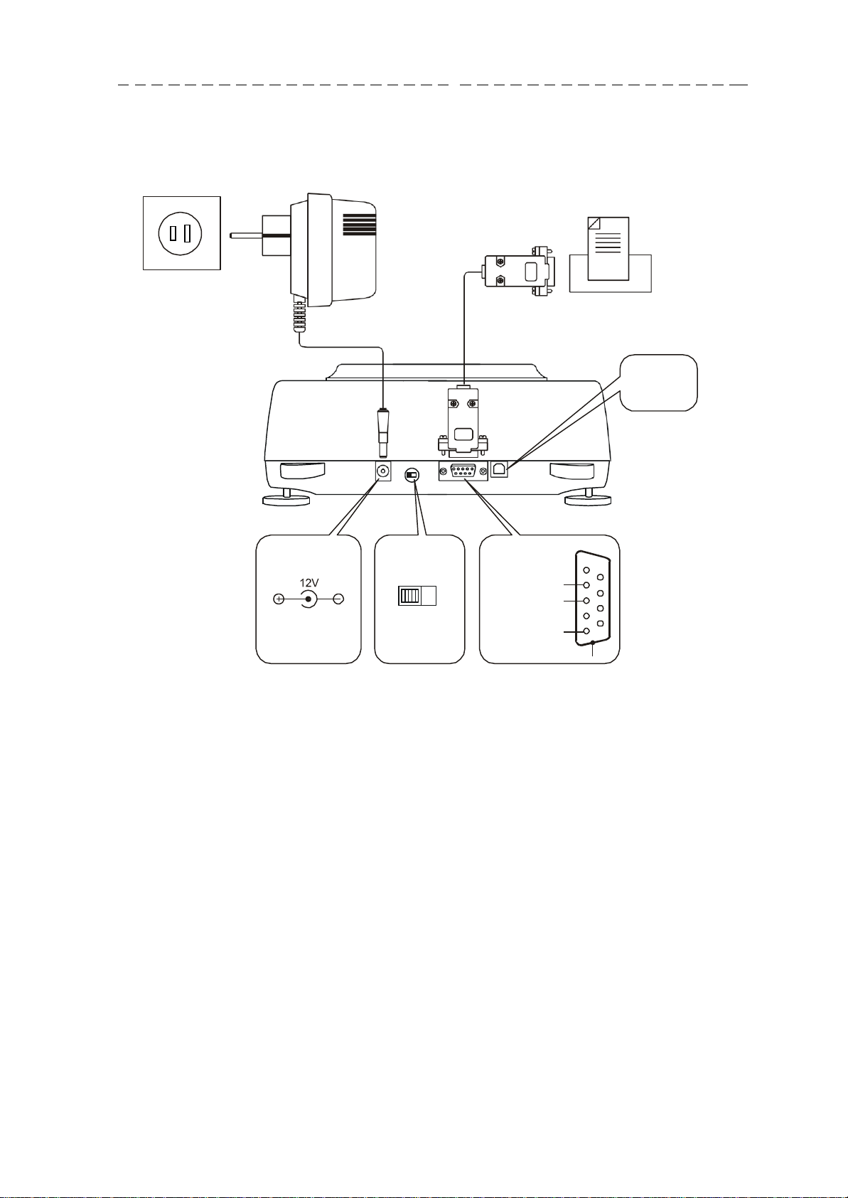
Connectors view:
~100V
Feeder Printer or computer
USB
Feeder
Adjustment
switching
ON OFF
RS232C
RxD (receiver)
TxD (transmitter)
ground
case
6
7
8
9
8
USER MANUAL
___
_ _ _ _ _ _ _ _ _ _ _ _ _ _ _ _ _ _
_____
_ _ _ _ _ _ _ _ _ _ _ _ _ _ _ _
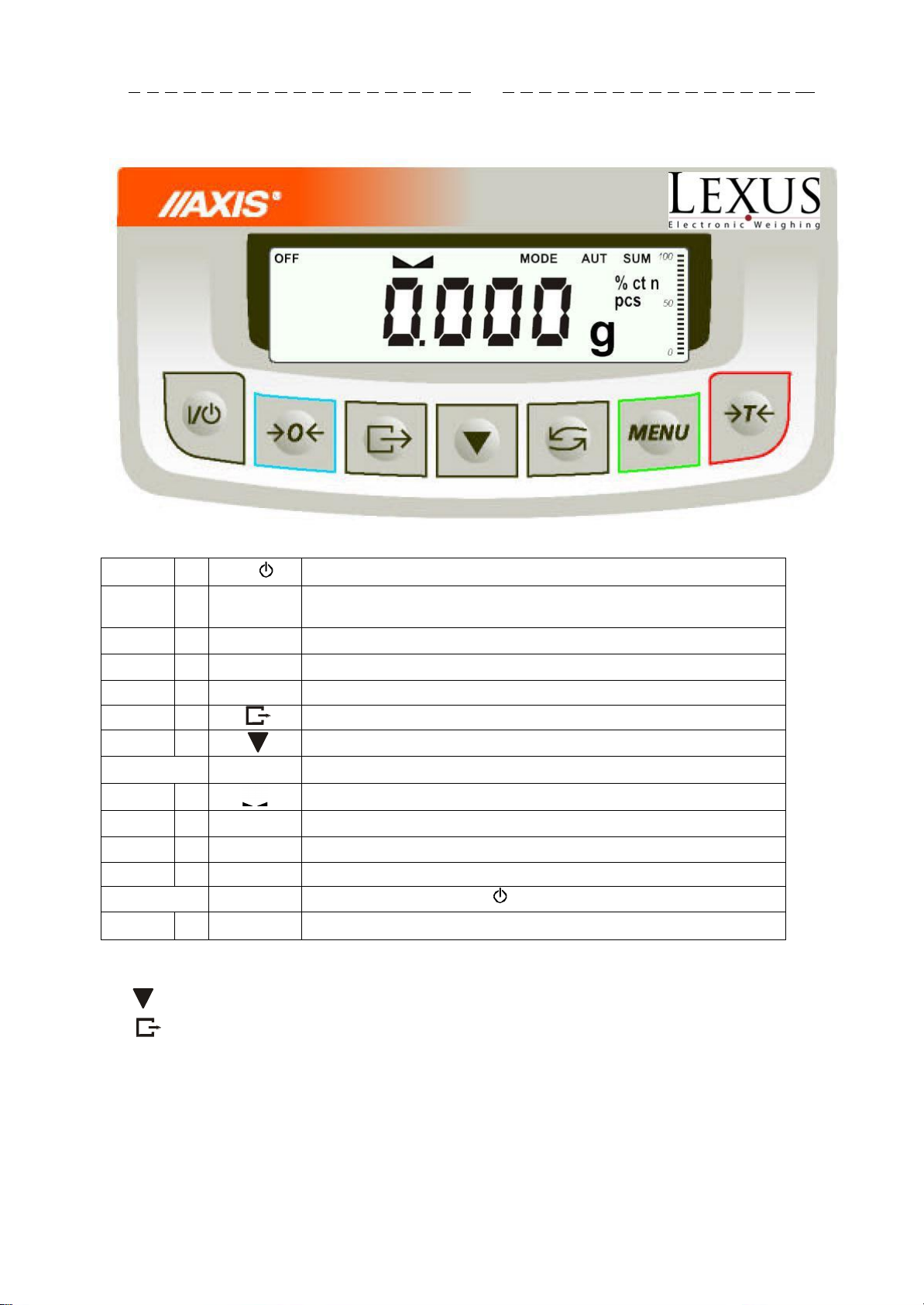
key
I/
- switch on / switch off (standby),
"
T
- taring (storing package mass subtracted from weighed
mass)
"
- change mode of balance work,
"
0
- zeroing the scale when pan is empty (option) ,
"
MENU
-special function menu,
"
- result printout,
"
- internal calibration / quick option view,
indicator
0
- zero indicator (when scale pan is empty),
"
- indicator of weighing result stabilisation,
"
NET
- net mass (after use of →T← key),
"
MODE
- indicator of switching special function on,
bar
indicator
- indicator of scale load (0-100%).
indicator
OFF
- switching scale with key (standby),
"
pcs
- indication in pieces
6. Keys and indicators
The use of keys during entering numeric values (special functions):
- Increment current digit,
- insert comma,
T - move to next position,
MENU - finish entering
Note:
0 keys and 0 indicators only work in balances with d=e.
9
USER MANUAL
___
_ _ _ _ _ _ _ _ _ _ _ _ _ _ _ _ _ _ _
__
_ _ _ _ _ _ _ _ _ _ _ _ _ _ _ _
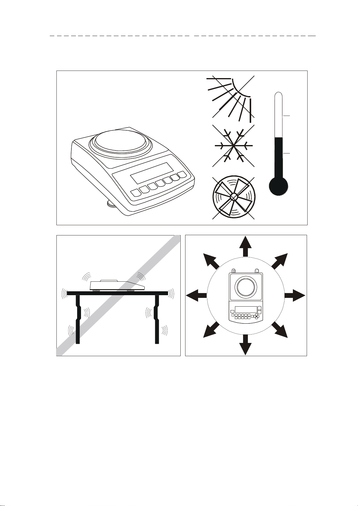
7. Preparing working environment
+33°C
+18°C
Location for the scale should be chosen with care in order to limit influence of the
factors that can interrupt working scale. This location has to maintain proper
temperature for working scale and necessary space for its operating. The scale should
stay on stable table made of material that does not influence magnetically on the
scale.
Rapid air blasts, vibrations, dust, rapid temperature changes or air humidity over 90%
are not allowed in scale surrounding. The scale should be far from heat sources and
devices emitting strong electromagnetic or magnetic fields.
10
USER MANUAL
___
_ _ _ _ _ _ _ _ _ _ _ _ _ _ _ _ _ _
_____
_ _ _ _ _ _ _ _ _ _ _ _ _ _ _ _
8. Preparing scale to work
7
6
Scale should be transported in the way, that there is no risk of
accidental pressing or overweighing a pan.
If the scale was taken from a lower temperature surrounding to a room with
9
8
1
2
3
1. Take the scale and feeder out of
the package. It is recommended to
keep the original scale package in
order to transport the balance safely
in future.
4
5
2. Place the scale on a stable ground
not affected by mechanical vibrations
and airflows.
3. Level the scale using rotating legs
6 so that the air bubble in water level
7 at the back of the scale is in the
middle.
4. Put draft shield 8 on the scale and
cover 9 on it.
higher temperature, e.g. in winter, moisture can liquefy on the scale casing.
Do not connect power supply to the scale, because this can cause damage
or improper work of the scale. In this case leave the scale for at least 4
hours unplugged for acclimatization.
11
USER MANUAL
___
_ _ _ _ _ _ _ _ _ _ _ _ _ _ _ _ _ _ _
__
_ _ _ _ _ _ _ _ _ _ _ _ _ _ _ _
9. General operation principles
1. In order to confirm correctness of the scale during its operation, before starting and
after finishing every valid measurement series it is recommended to check weighing
accuracy putting calibration weight or other object of exactly kno wn mass on the
scale. In the case when allowable measurement error of the scale is exceeded, it is
recommended to perform calibration with external weight or contact authorised
service centre.
2. Weighed mass should be placed in the middle of the pan.
3. The scale allows taring in the whole measuring range. To tare the scale press
->T<- key. Taring does not extend measuring range, but only subtracts tare value
from mass value of a sample placed on the pan. To make the control of a load on
the pan easier and to avoid exceeding measurement range, the scales have load
indicator calibrated 0÷100%.
4. Weighing result should be read when the indicator lights, which signalises
result stabilisation.
5. When the scale is not used but it is necessary for it to be ready to work, it can be
switched off by pressing I/ key. The scale reading system is then switched off and
scale goes to standby mode signalled with OFF indicator. Switching the scale on is
preformed by pressing I/ key.
6. In sales having →0← key (zeroing) active it should be checked if zero indicator
→0← is displayed before sample is placed on the pan. If not, press →0← key and
wait until the scale is zeroed and zero indicator appears. After that load can be
placed on scale pan.
7. Scale mechanism is a precise device sensitive to overweight, mechanical shocks
and strokes.
8. After every change of balance position, level the balance and perform internal
calibration.
Do not overload the scale more than 20% of maximum capacity.
Do not press the pan with a hand.
For transportation time, pan support and pan ring should be packed
separately.
12
USER MANUAL
___
_ _ _ _ _ _ _ _ _ _ _ _ _ _ _ _ _ _
_____
_ _ _ _ _ _ _ _ _ _ _ _ _ _ _ _
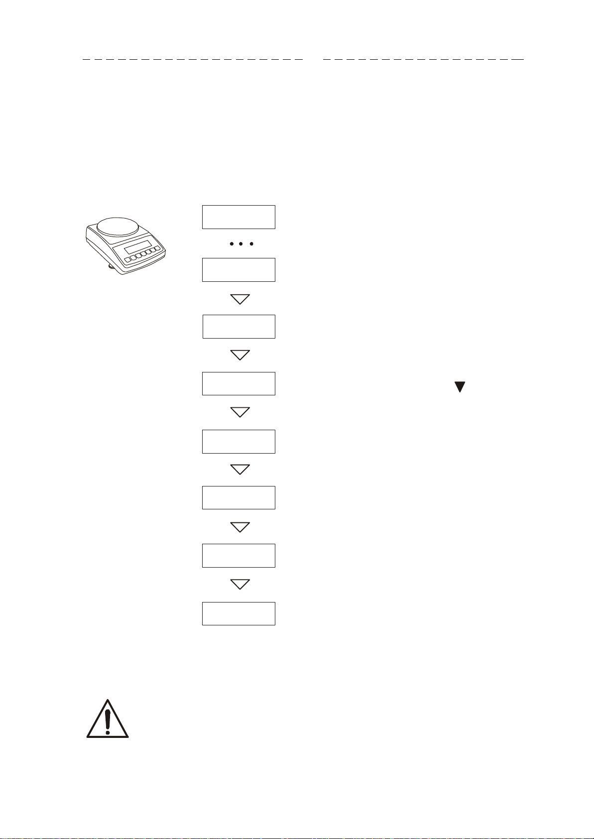
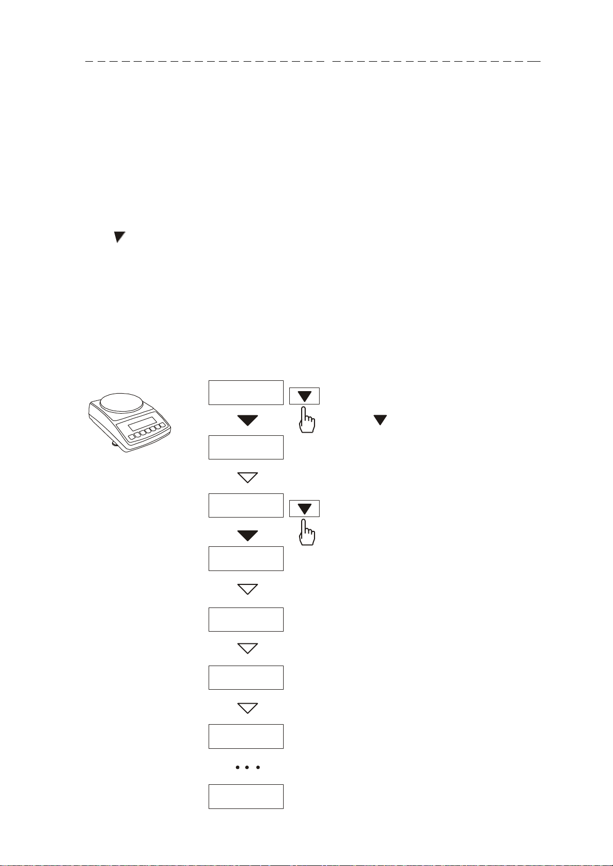
10. Start-up
Plug feeder into ~230V power supply socket. When the pan is empty plug feeder
output connector into 12V socket at back of the scale. Autotests and internal
calibration will be performed.
C-1
C-6
Tests of electronic scale components.
(displayed only when any test result is
negative)
Showing scale program version.
Internal calibration (press key if You
want to terminate calibration)
Steps after start-up of the scale:
AtA...
-d0Wn-
-UP-
CCCC
-------
0.00g
It is recommended that before you start measuring the internal
temperature has stabilized weight. For this to happen, the weight
should remain enabled for at least 2 hours. To maintain the accuracy
of the weight is not recommended to turn off the power.
Zeroing the scale.
Ready to work.
13
USER MANUAL
___
_ _ _ _ _ _ _ _ _ _ _ _ _ _ _ _ _ _ _
__
_ _ _ _ _ _ _ _ _ _ _ _ _ _ _ _
11. Internal calibration
The balance is equipped with internal calibration system, which general task is to
maintain required measurement accuracy on the balance.
Internal calibration is the process of putting internal weight on automatically by
balance mechanism and correcting accuracy in balance firmware. The correction is
necessary because of differences between values of gravitational acceleration in
the place where the balance was manufactured and in the place where it is
operated, as well as due to changes of balance level and temperature.
Internal calibration is performed in the following situations:
- when key is pressed twice,
- after defined time interval (for balances comply with verification requirements - 2
hours),
- after temperature change (for balances comply with verification requirements –
more than 2oC).
For balances comply with verification requirements time interval is set to 2 hours and
defined temperature change is 1oC. In other balances those values can be set as
calibration options. The reason of starting internal calibration is shown as an icon near
weight picture.
In order to perform internal calibration
0.00
PrESS
g
proceed with the following:
Empty the pan.
Press key twice (double pressing
the key helps to avoid accidental
starting calibration procedure).
During calibration internal weight is
put three times on and obtained
A
GAIn
-d0Wn-
-UP
-
CCCC
results are compared.
Discrepancy of results is signalled
with a message and causes the
balance being blocked.
Until calibration process is finished do
not perform any operation on the
balance. Any vibrations and shocks
interfere calibration process and may
delay it or deteriorate accuracy of its
result.
When internal calibration is performed
successfully the balance indicates
zero on the display at empty pan.
-------
0.00g

14
USER MANUAL
___
_ _ _ _ _ _ _ _ _ _ _ _ _ _ _ _ _ _
_____
_ _ _ _ _ _ _ _ _ _ _ _ _ _ _ _
Note:
In order to terminate internal calibration process in balances not comply with
verification requirements press key and wait until balance mechanism is not
settled in initial position.
12. Checking the balance
In order to confirm correctness of the balance during its operation, before starting and
after finishing every measurement series it is advised to check weighing accuracy. It
can be done by weighing external calibration weight or other object with exactly known
mass.
If exceeding of allowable measurement error is affirmed, the following things should
be checked:
- if the balance stands stable and it is levelled,
- if the balance is exposed on rapid air blasts, vibrations, rapid temperature
changes or air humidity,
- if the balance is not affected directly by heat source, electromagnetic radiation
or magnetic field.
The cause of inaccuracy can be too low temperature of the balance as well, when it
was unplugged from power supply. In this situation leave the bal ance switched on for
several minutes in order to adjust its internal temperature.
If none of above causes of inaccuracy occurs, calibration with external weight should
be performed to the balance. Recommended external calibration weight (to buy for
additional charge) is given in technical data table. In order to calibrate the balance with
external weight in legally verified balances verification seals should be removed and
another legal verification should be performed. In this case it is recommended to
contact authorized service centre.
Calibration with external weight is described in details in chapter 15.7.

15
USER MANUAL
___
_ _ _ _ _ _ _ _ _ _ _ _ _ _ _ _ _ _ _
__
_ _ _ _ _ _ _ _ _ _ _ _ _ _ _ _
7
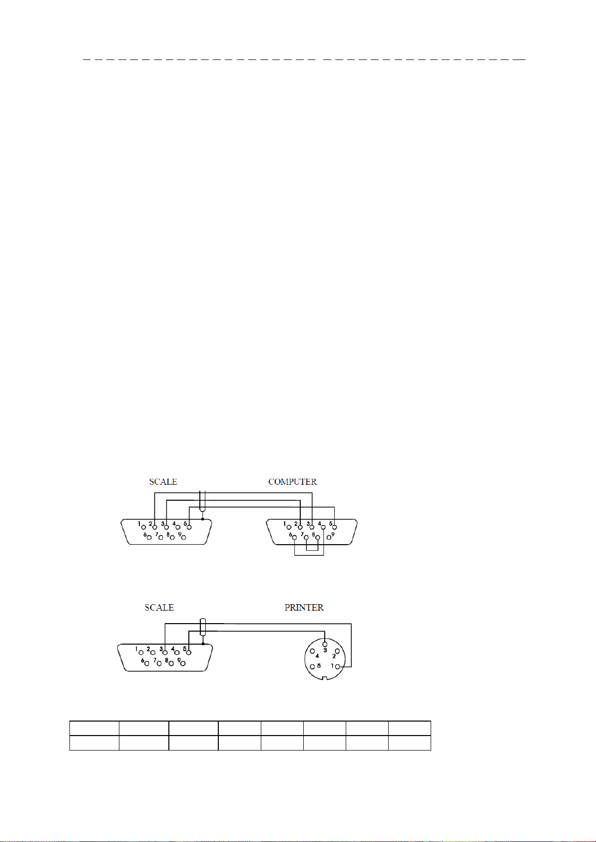
13. Connection with computer or a printer
The scale may send data to a computer or a printer via RS232C interface.
RxD
(receiver)
TxD (transmitter)
GND
1
2
3
4
5
6
8
9
Case
When cooperating with a computer, the scale
sends weighing result after initialising signal
from a computer or after pressing key on
the scale.
For cooperation with the scale a computer
should be equipped with software allowing
receiving data from the scale and using it
further.
- Communication – free program for sending simple commands to the scale and
receiving weighing results,
- ProCell – program for cooperation with Microsoft EXCEL and other Microsoft
Windows applications (demo version).
Three modes of work serial connections are possible:
- standard mode (stb - with stabilization of indicator or without)
- automatic mode (auto)
- continuous mode (Cont.)
Special function (SErIAL) is serve to choice a type of work serial connector (see
below).
Standard type.
Scale sends result of weighting on an initialize signal from computer, or after pressed
key.
Automatic mode (this mode can be use to cooperation with a printer)
Data are send automatically after result stabilization, but next transmission is possible
after removing previously weighted sample. Data contains next number of sample and
result of weighting.
Continuous mode.
Scale sends result of weighting on each 0,1 seconds.

16
USER MANUAL
___
_ _ _ _ _ _ _ _ _ _ _ _ _ _ _ _ _ _
_____
_ _ _ _ _ _ _ _ _ _ _ _ _ _ _ _
Byte
1 - sign „-” or space
Byte
2 - space
Byte
34
-
digit or space
Byte
5÷9
-
digit, decimal point or space
Byte
10 - digit
Byte
11 - space
Byte
12 - k, l, c, p or space
Byte
13 - g, b, t, c or %
Byte
14 - space
Byte
15 - CR
Byte
16 - LF
Detailed protocol description in standard mode
LonG protocol
Transmission proceeds in the following way:
1. Communication parameters: 8 bits, 1 stop bit, no parity, baud rate 4800bps,
2. Available orders send from computer and balance answers:
Readout of scale indication ( corresponds to pressing key
ComputerScale: S I CR LF (53h 49h 0Dh 0Ah),
ScaleComputer: scale response according to description below (16 bytes):
Attention:
Network number different than zero (SErIAL / nr function) changes scale working
mode: communication with a computer is possible after logging the scale in with 02h
scale number command. To log the scale out use 03h command.
For example: Using a program to test RS232 interface for scale number 1 please
write: $0201 to log in, then SI, and write: $03 to close communication.
Asking for scale presence in system (testing scale connection with computer):
ComputerScale: S J CR LF (53h 4Ah 0Dh 0Ah),
ScaleComputer: M J CR LF (4Dh 4Ah 0Dh 0Ah),
Displaying a sign on scale display (text message from computer):
ComputerScale: S N n n X X X X X X CR LF (53h 4Eh 0Dh 0Ah), nndisplaying time in seconds; XXXXXX- signs to display
ScaleComputer: M N CR LF (4Dh 4Eh 0Dh 0Ah),
Scale tarring (calling T key press) :
ComputerScale: S T CR LF (53h 54h 0Dh 0Ah),
ScaleComputer: without response,
Scale zeroing (calling 0 key press):
Computer Scale: S Z CR LF (53h 5Ah 0Dh 0Ah),
Scale Computer: without response,
Scale turning on / off (calling I/ key press):
Computer Scale: S S CR LF (53h 53h 0Dh 0Ah),
17
USER MANUAL
___
_ _ _ _ _ _ _ _ _ _ _ _ _ _ _ _ _ _ _
__
_ _ _ _ _ _ _ _ _ _ _ _ _ _ _ _
SW-1
SW-2
SW-3
SW-4
SW-5
SW-6
SW-7
SW-8
on
off
on
off
off
on
off
off
Scale Computer: without response,
Entering to special function menu (calling MENU key press):
Computer Scale: S F CR LF (53h 46h 0Dh 0Ah),
Scale Computer: without response,
Setting low threshold value (option):
Computer Scale: S L D1...DN CR LF (53h 4Ch D1...DN 0Dh 0Ah)
D1...DN – threshold value, maximum 8 characters („-” – negative value, digits, dot
– decimal separator), number of digits after dot should be the same as on scale
display,
Scale Computer: without response,
Example:
in order to set low threshold 1000g in scale B1.5 (d=0.5g) the following order
should be sent:
S L 1 0 0 0 . 0 CR LF (53h 4Ch 31h 30h 30h 30h 2Eh 30h 0Dh 0Ah),
in order to set low threshold 100kg in scale B150 (d=50g) the following order
should be sent:
S L 1 0 0 . 0 0 CR LF (53h 4Ch 31h 30h 30h 2Eh 30h 30h 0Dh 0Ah),),
Setting high threshold value (option):
Computer Scale: S H D1...DN CR LF (53h 48h D1...DN 0Dh 0Ah),
D1...DN – threshold value (see )
Scale Computer: without response.
Connecting cable WK-1 (scale – computer / 9-pin interface):
Connecting cable WD-1 (connects printer with scale):
AXIS C-001 printer internal switches setting:
 Loading...