

Page 1
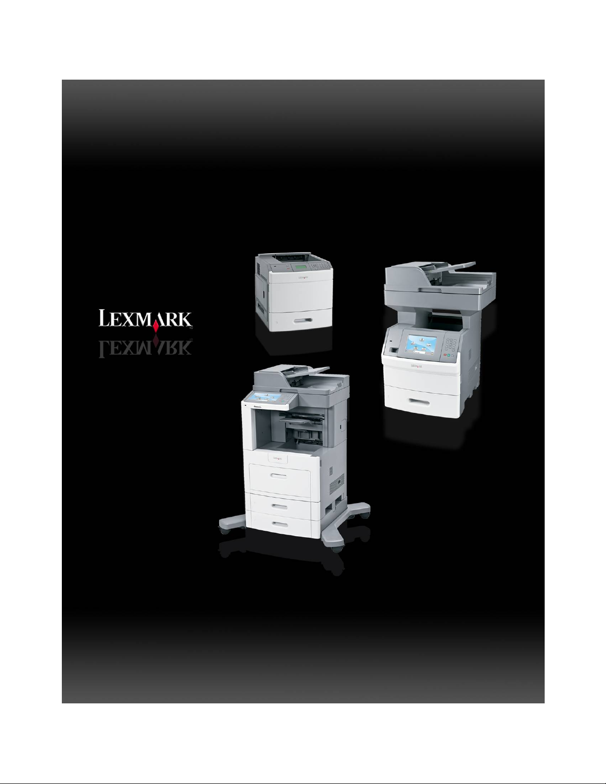
Lexmark T65x
Lexmark X65x
Page 2

Mono Laser Printer Study Guide
THIS PAGE INTENTIONALLY LEFT BLANK
Page 3

Lexmark T65x and X65x Mono Product Study Guide Rev 1.47
Edition: October 2008
Revision: 1.47
The following paragraph does not apply to any country where such provisions are inconsistent with local
law: LEXMARK INTERNATIONAL, INC. PROVIDES THIS PUBLICATION “AS IS” WITHOUT WARRANTY OF ANY
KIND, EITHER EXPRESS OR IMPLIED, INCLUDING, BUT NOT LIMITED TO, THE IMPLIED WARRANTIES OF
MERCHANTABILITY OR FITNESS FOR A PARTICULAR PURPOSE. Some states do not allow disclaimer of
express or implied warranties in certain transactions; therefore, this statement may not apply to you.
This publication could include technical inaccuracies or typographical errors. Changes are periodically made to the
information herein; these changes will be incorporated in later editions. Improvements or changes in the products or
the programs described may be made at any time.
Comments may be addressed to Lexmark International, Inc., Department 352X/008-4, 740 West New Circle Road,
Lexington, Kentucky 40550, U.S.A or e-mail at [email protected]. Lexmark may use or
distribute any of the information you supply in any way it believes appropria te without incurring any obligation to you.
References in this publication to products, programs, or services do not imply that the manufacturer intends to make
these available in all countries in which it operates. Any reference to a product, program, or service is not intended to
state or imply that only that product, program, or service may be used. Any functionally equivalent pro duct, program,
or service that does not infringe any existing intellectual property right may be used instead. Evaluation and
verification of operation in conjunction with other products, programs, or services, except those expressly designated
by the manufacturer, are the user’s responsibility.
Lexmark and Lexmark with diamond design are trademarks of Lexmark International, Inc., registered in the United
States and/or other countries.
PCL® is a registered trademark of the Hewlett-Packard Company.
All other trademarks are the property of their respective owners.
© 2007 Lexmark International, Inc. All rights reserved.
UNITED STATES GOVERNMENT RIGHTS
This software and any accompanying documentation provided und er this agreement are commercial computer
software and documentation developed exclusively at private expense.
For Training Purposes Only 6/3/2009
Page 4

Lexmark T65x and X65x Mono Product Study Guide Rev 1.47
THIS PAGE INTENTIONALLY LEFT BLANK
For Training Purposes Only 6/3/2009
Page 5

Lexmark T65x and X65x Mono Product Study Guide Rev 1.47
Table of Contents
TECHNICAL INFORMATION .........................................................................................1
T65X PRINTER SPECIFICATIONS..........................................................................................................1
T65X BASIC MODEL ...........................................................................................................................1
FULLY CONFIGURED T65X MODEL......................................................................................................2
T65X OPTIONS AND FEATURES...........................................................................................................3
T65X AND X65X SUPPLY ITEM COMPATIBILITY ....................................................................................3
X65X SPECIFICATIONS .......................................................................................................................4
X65X BASIC MODELS.........................................................................................................................4
X65X OPTIONS: .................................................................................................................................4
X65X OPTIONS: .................................................................................................................................5
THEORY OF OPERATION.............................................................................................6
PRINTER PAPER PATH........................................................................................................................6
Internal Duplex: Models T652 & T654................................................................................6
Duplex: Models T650..........................................................................................................7
PRINT ENGINE TRANSPORT SYSTEM ...................................................................................................8
Paper Tray Components.....................................................................................................8
Multiple Sheet Feed Prevention..........................................................................................8
ELECTROPHOTOGRAPHIC PROCESS....................................................................................................9
Charge: ...............................................................................................................................9
Exposure:
Development:
Transfer:..............................................................................................................................9
Fusing: ................................................................................................................................9
Cleaning:.............................................................................................................................9
EP (ELECTROPHOTOGRAPHIC) COMPONENTS – T65X DIAGRAM ........................................................10
PRINTHEADS [OSCILLATING VS. SPINNING POLYGON MIRROR]...........................................................11
T650 & T650n ...................................................................................................................11
T652dn & T654dn .............................................................................................................11
............................................................................................................................9
......................................................................................................................9
POLYGON & OSCILLATING PRINTHEAD ASSEMBLY ADJUSTMENT.........................................................12
OSCILLATING PRINTHEAD ASSEMBLY ELECTRONIC ADJUSTMENT ........................................................14
ALIGNMENT ASSEMBLY – SKEW ADJUSTMENT....................................................................................15
DOCUMENT SCANNING .....................................................................................................................17
For Training Purposes Only 6/3/2009
Page 6

Lexmark T65x and X65x Mono Product Study Guide Rev 1.47
Document scanning at ADF..............................................................................................17
Document scanning at platen ...........................................................................................17
Names and functions of components................................................................................17
DOCUMENT FEED PATH FROM THE ADF.............................................................................................19
Names and functions of components................................................................................20
ADF...................................................................................................................................20
SCANNER MANUAL REGISTRATION ...................................................................................................21
OPERATOR PANELS .................................................................................................. 22
T65X PANEL BUTTONS.....................................................................................................................22
UNDERSTANDING THE X65X PRINTER CONTROL PANEL.....................................................................23
UNDERSTANDING THE ADF (AUTOMATIC DOCUMENT FEED) & SCANNER GLASS .................................24
UNDERSTANDING THE HOME SCREEN ................................................................................................25
CUSTOMER MENUS ..........................................................................................................................26
SERVICE MODE ................................................................................................................................27
Confirm the installation status...........................................................................................27
Power-on Reset sequence................................................................................................27
Entering Diagnostics mode on the T65x...........................................................................27
Accessing service menus on the X65x.............................................................................28
Accessing SE menu on the X65xe MFP and T65x printer................................................28
MIRRORED MVRAM....................................................................................................28
PRINT QUALITY DIAGNOSTICS................................................................................. 28
PRINT QUALITY PAGES (PRT QUALITY PGS).......................................................................................29
ISOLATING PRINT QUALITY PROBLEMS...............................................................................................29
Repeating defects.............................................................................................................30
Solid Black ........................................................................................................................31
Blank print (no print)..........................................................................................................32
Spots.................................................................................................................................33
Solid black or white streaks ..............................................................................................34
Vertical Stripes (process direction)...................................................................................35
Horizontal stripes (side to side direction...........................................................................36
Vertical void lines and bands (process direction...............................................................37
Horizontal white stripes or bands (side to side direction).................................................38
Ghost images (sometimes called after image) .................................................................39
Print irregularities, Voids, Partial Lack..............................................................................40
Faint print (Low contrast) ..................................................................................................41
For Training Purposes Only 6/3/2009
Page 7

Lexmark T65x and X65x Mono Product Study Guide Rev 1.47
Background (fog)...............................................................................................................42
Skew .................................................................................................................................43
Media Damage..................................................................................................................44
No fuse (unfused toner, smearing) ...................................................................................45
PAPER TRANSPORT DIAGNOSTICS.........................................................................46
PAPER RULES OF THUMB .................................................................................................................46
UNDERSTANDING JAM NUMBERS AND LOCATIONS ............................................ 47
200 AND 201 PAPER JAMS................................................................................................................48
202 AND 203 PAPER JAMS................................................................................................................49
230 PAPER JAM...............................................................................................................................49
Rear Paper Jams..............................................................................................................49
Front Paper jams...............................................................................................................51
231-239 PAPER JAMS (OPTIONAL EXTERNAL DUPLEX UNIT)................................................................51
Front Paper Jam ...............................................................................................................52
241-245 PAPER JAMS ......................................................................................................................52
250 PAPER JAM................................................................................................................................53
260 PAPER JAM................................................................................................................................53
271-279 PAPER JAMS ......................................................................................................................54
280 PAPER JAM................................................................................................................................54
281 PAPER JAM................................................................................................................................55
282 PAPER JAM................................................................................................................................55
283 STAPLE JAM ..............................................................................................................................56
290-294 PAPER JAMS ......................................................................................................................57
POTENTIAL FIELD ISSUES ........................................................................................58
GENERAL NOTES:...................................................................................................... 61
Mirrored MVRAM ..............................................................................................................61
Operator Panel Assembly Cable – X65x ..........................................................................61
LEXMARK T65X PRINT DRIVER– CORE SKILLS COURSE ..................................... 62
DIAGNOSTIC TOOLS AVAILABLE FOR TECHNICIANS...........................................62
SERVICE MANUALS..........................................................................................................................62
TECHNICAL SERVICE BULLETINS.......................................................................................................62
For Training Purposes Only 6/3/2009
Page 8

Lexmark T65x and X65x Mono Product Study Guide Rev 1.47
THIS PAGE INTENTIONALLY LEFT BLANK
For Training Purposes Only 6/3/2009
Page 9
Lexmark T65x and X65x Mono Product Study Guide Rev 1.47
TECHNICAL INFORMATION
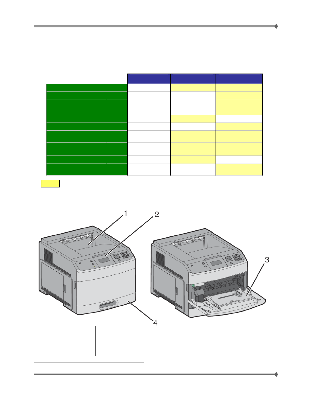
T65x Printer Specifications
Speed - Letter ppm
Processor MHz
Memory - Std / Max MB
Solutions ready - eSF/USB-A
Input - std / max
Output
Duplex
Duty Cycle pg/mo
Cartridge - SWE
Cartridge Aftermarket
Cells Shaded Yellow indicate improved feature vs. lower model.
T650n T652n T654n
45 50 55
500 500 600
128 / 640 128 / 640 256 / 1280
No No Yes
100+250 / 4000 100+550 / 4300 100+550 / 4300
350 350 550
optional
200K
Rec 3K - 20K
7K 10K 10K
7K / 25K 7K / 25K 7K / 25K / 36K
Internal Dup
model
225K
Rec 3K - 30K
T65x Basic Model
Internal Dup
model
275K
Rec 5K - 35K
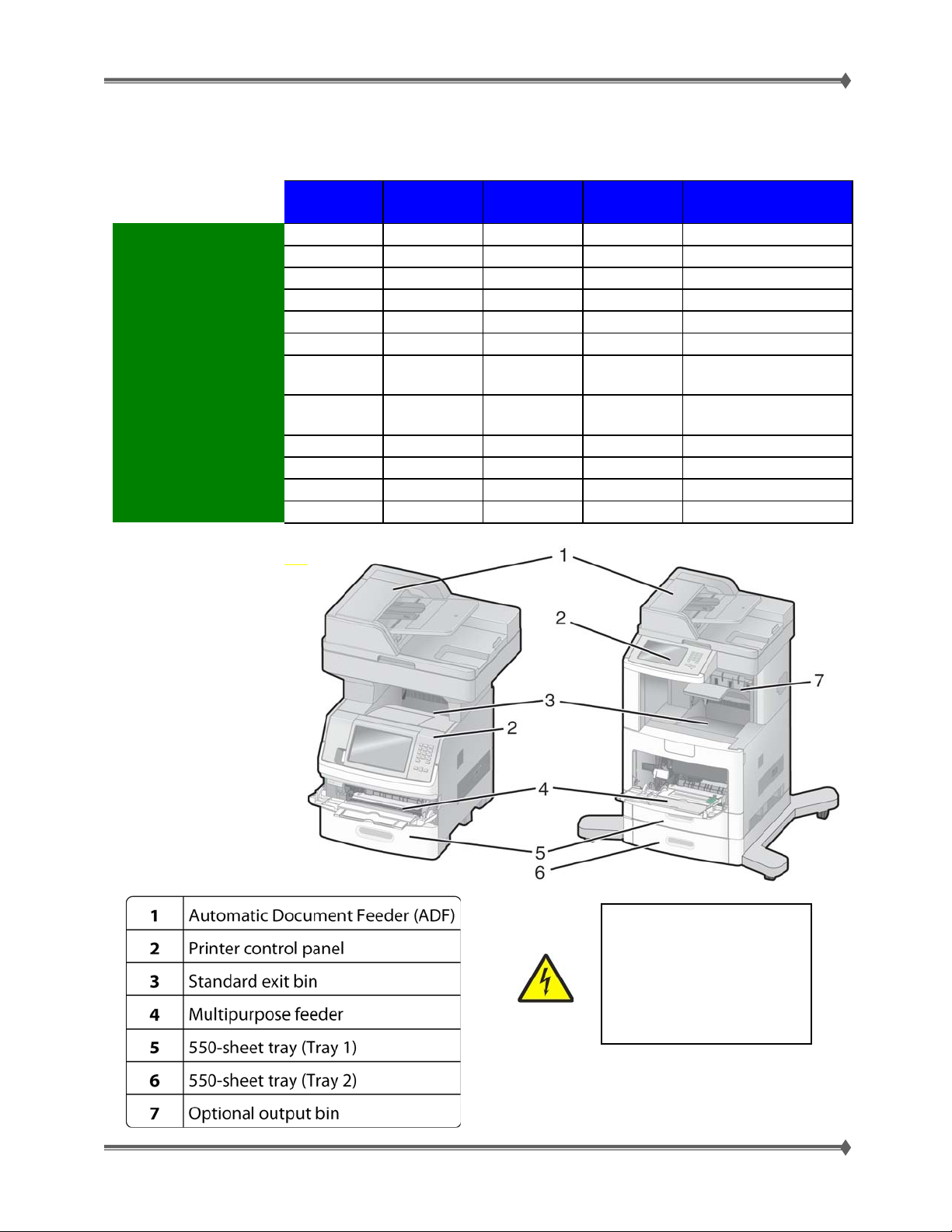
1
Feature Paper Capacity
1 Standard Exit Bin 350- or 550-sheet
2 Printer Control Panel NA
3 Multipurpose Feeder 100 Sheets
4 Standard Tray (tray 1 250- or 550-sheets
1
Based on 75 g/m2 (20 lb.) paper
For Training Purposes Only 6/3/2009
1
Page 10
Lexmark T65x and X65x Mono Product Study Guide Rev 1.47
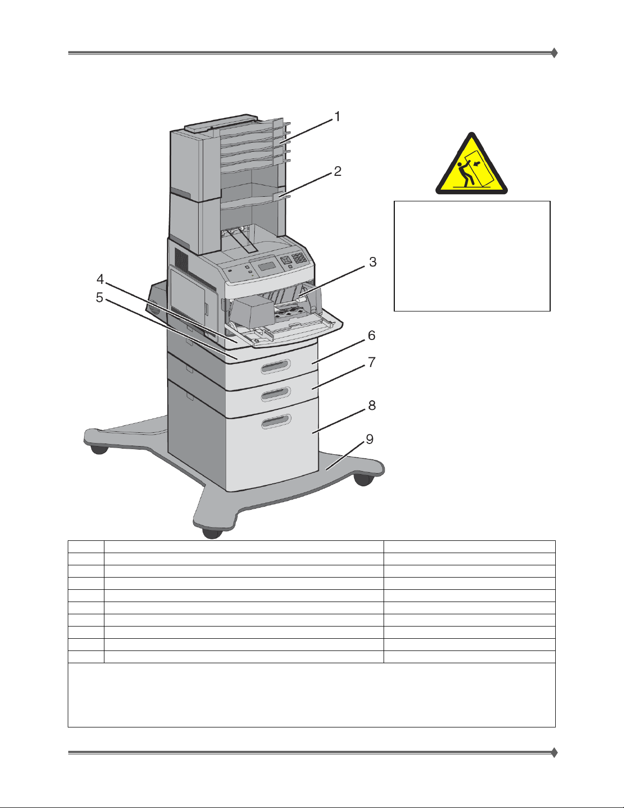
Fully Configured T65x Model
CAUTION: –TIPPING HAZARD:
Floor-mounted configurations
require additional
furniture for stability. You must
use either a printer stand or
printer base if you are using
a 2000-sheet tray, a duplex unit,
and an input option, or more than
one input option.
Feature/Option Paper Capacity 1
5-bin mailbox 2 500 sheets
1
Output expander 3 650 sheets
2
Envelope feeder 85 envelopes
3
Standard tray (Tray 1) 250- or 550-sheets
4
Duplex unit 4 Not applicable
5
Optional tray (Tray 2) 250- or 550-sheets
6
Optional tray (Tray 3) 250- or 550-sheets
7
Optional 2000-sheet tray (Tray 4) 2000 sheets
8
Caster Base Not applicable
9
1 Based on 75 g/m2 (20 lb.) paper.
2 Up to two 5-bin mailbox units are supported.
3 The printer supports up to three output expander units, or one output expander combined with one 5-bin mailbox,
one high capacity output expander (not depicted), or one stapler unit (not depicted).
4 Optional external duplex unit available for basic T650x model. T652x and T654x have an internal duplex unit if it has
been ordered as a factory install. Duplex for the T652x and T654x is not a field installabl e option.
For Training Purposes Only 6/3/2009
2
Page 11
Lexmark T65x and X65x Mono Product Study Guide Rev 1.47
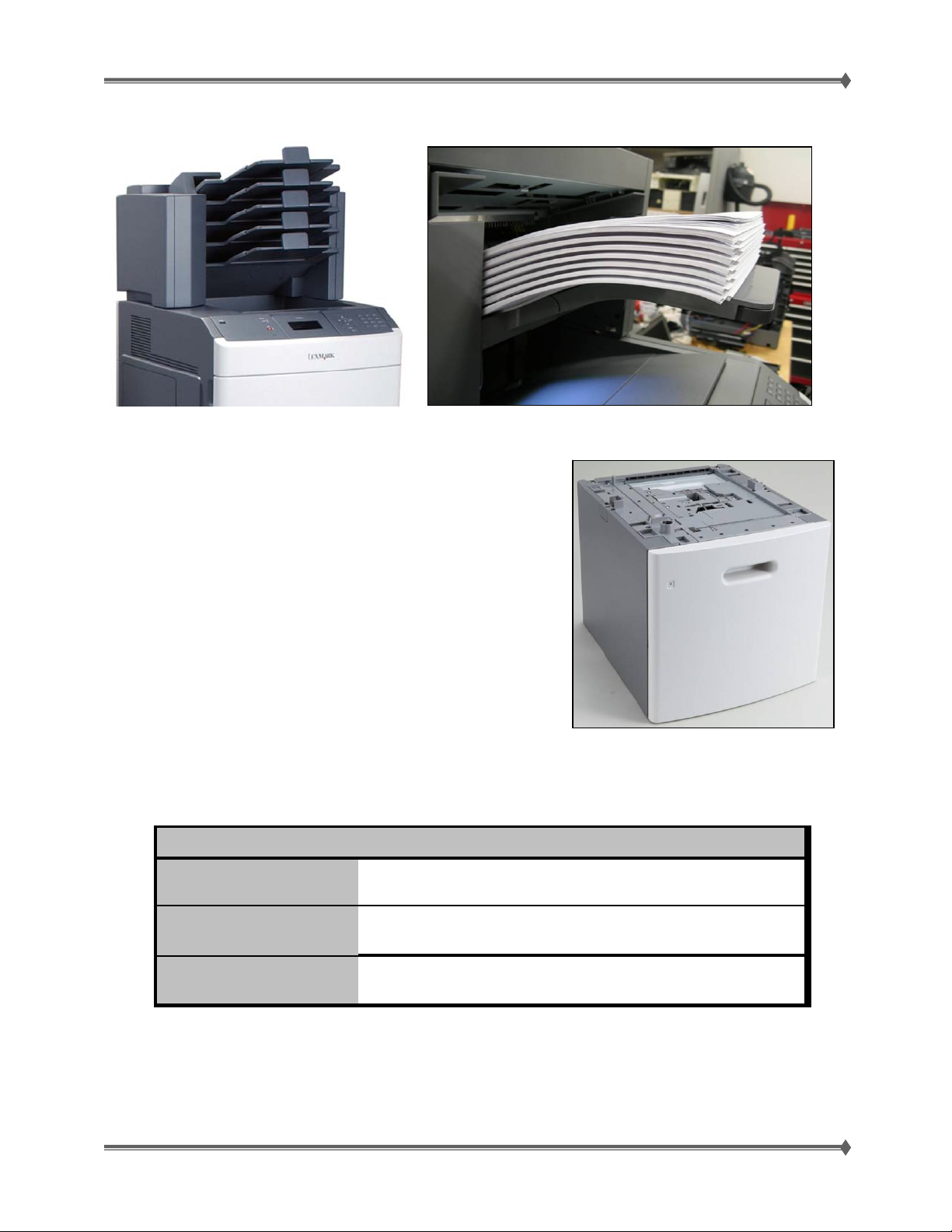
T65x Options and Features
New Mailbox Option / LED Indicators Stapler / 50 sheet capacity, offset stapled output,
Redesigned output high capacity tray.
Tray pulls out and drop paper in
Vs. door with an elevator
No separate power cord needed
New pick tires apply here too
LED output bin light
T65x and X65x Supply Item Compatibility
T65x
"H"
"M"
"L"
• T65x cartridges will work in the X65x, but not vice-versa
7K 25K 36K
999
99
99
Ø
Ø
• The (high yield) 36K T65x cartridge will not work in the T650, T652 or the X651 or X652.
• No backward/forward compatibility with the T64x series printers
For Training Purposes Only 6/3/2009
3
Page 12
Lexmark T65x and X65x Mono Product Study Guide Rev 1.47
X65x Specifications
Functions
Print (Letter) ppm
Memory std/max
HardDrive
Dupl e x Sc an
Op Panel
Input Cap. st d/ m ax
Out put st d/ma x
Caster Base
SWE Y i e l d
AM Yield
Ma x Du ty Cy c l e
X651de X652de X654de
3444 4
45 45 55 55 55
256 / 768 256 / 768 256 / 768 256 / 768 256 / 768
Opti onal Opti onal Opti onal 80 GB 80 GB
No-Simplex No-Simplex Yes-DADF Yes-DADF Yes-DADF
7" color 7" color 9" color 9" color 9" c olor
550+100 /
3,200
550 / 550 550 / 550 550 / 550 550 / 550
Optional Optional Optional Optional Yes
7K 7K 18K 18K 18K
7, 25K 7, 25K 7, 25, 36K 7, 25, 36K 7, 25, 36K
200k 200k 250k 250k 250k
550+100 /
3,200
550+100 /
3,200
X656de
(X656dte)
550+100 /
3,200
X658 d e(dfe/dme)
X658dte(dtfe/dtme)
(550+550)+ 100 / 2, 300
1,050 / 1, 050
(950 w/ mai l box)
X65x Basic Models
CAUTION: Do not set up
this product or make any
electrical or cabling
connections, such as the
power cord or options and
features, during a lightning
storm.
NOTE: All of the X658 paper trays are
wider than the rest of the T65x & X65x
family and are NOT interchangeable!
For Training Purposes Only 6/3/2009
4
Page 13

Lexmark T65x and X65x Mono Product Study Guide Rev 1.47
X65x Options:
The following options are available. Some options are not available in every country or region. Contact
your point of purchase for options available in your country or region.
Available internal options
• Memory cards
— Printer memory
— Flash memory
— Fonts
• Firmware cards
— Bar Code and Forms
— IPDS and SCS/TNe
— PrintCryptionTM
— PRESCRIBE
• Printer hard disk
• LexmarkTM Internal Solutions Ports (ISP)
— RS-232-C Serial ISP
— Parallel 1284-B ISP
— MarkNetTM N8150802.11 b/g/n Wireless ISP
— MarkNet N8130 10/100 Fiber ISP
— MarkNet N8120 10/100/1000 Ethernet ISP
• MarkNet N8110 V-34 Fax Card
Media handling options
— 250- and 550-sheet paper trays of A4, letter, A5, B5, Executive, folio, statement, and
legal size
— 250-sheet universally adjustable tray
— 250- and 550-sheet paper drawers
— 2000-sheet high-capacity feeder
— Envelope feeder
— Duplex option–250-sheet
— Duplex option–550-sheet
— Output expander
— High-capacity output stacker
— StapleSmart™ Finisher
— 5-bin Mailbox
— Vertical Kiosk Presenter
— Horizontal Kiosk Presenter
For Training Purposes Only 6/3/2009
5
Page 14
Lexmark T65x and X65x Mono Product Study Guide Rev 1.47
THEORY OF OPERATION
Printer Paper Path
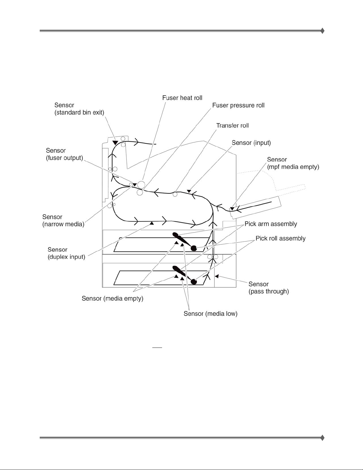
Internal Duplex: Models T652 & T654
NOTE:
Duplex on the T652 or the T654 is not
a field installable option. In order for a model
T652 or a model T654 to have duplex capability, it must be ordered that way initially.
On rare occasions you may encounter a simplex T652x or T654x that has had the
duplex option disabled at the factory to satisfy a customer’s requirement. In this
situation, the duplex hardware has not been removed. The disabling action is not
reversible in the field.
For Training Purposes Only 6/3/2009
6
Page 15
Lexmark T65x and X65x Mono Product Study Guide Rev 1.47
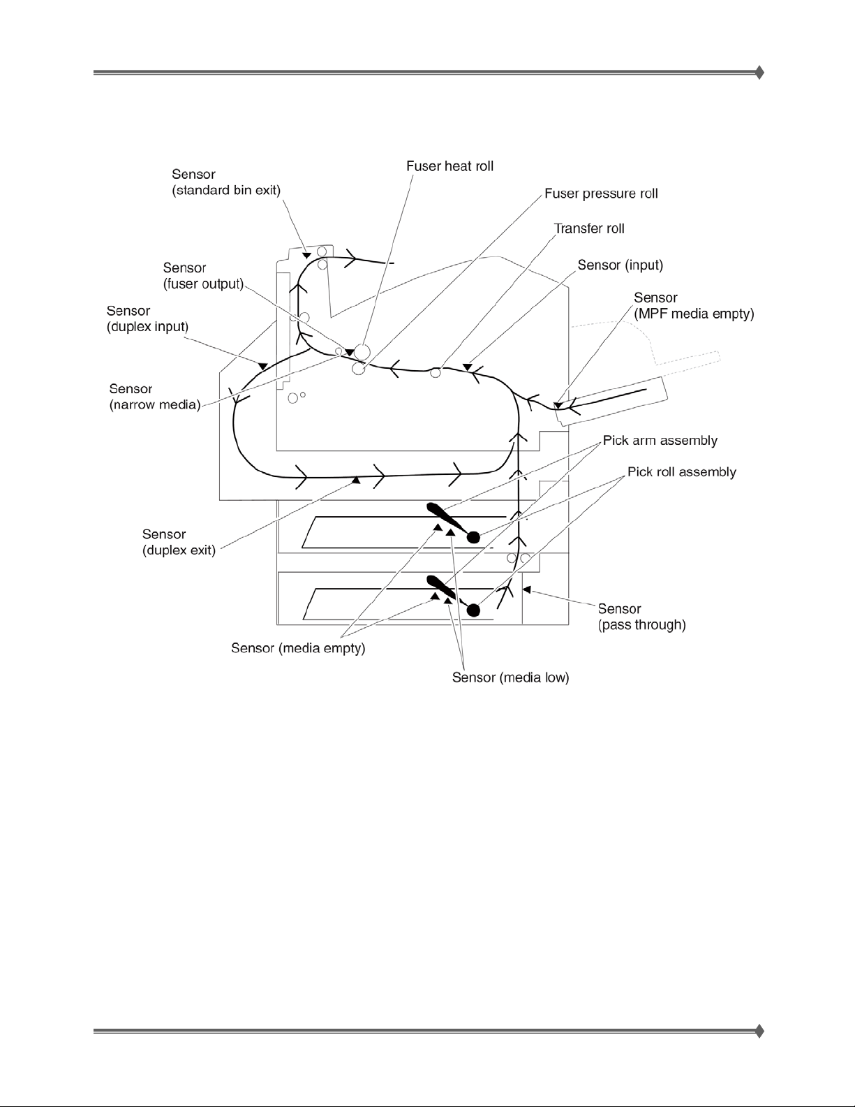
Duplex: Models T650
Duplex is a field installable option for model T650 only. It is functionally the same
theory of operation & uses the same basic paper path as did the T64x series printers.
For Training Purposes Only 6/3/2009
7
Page 16
Lexmark T65x and X65x Mono Product Study Guide Rev 1.47
Print Engine Transport System
Paper Tray Components
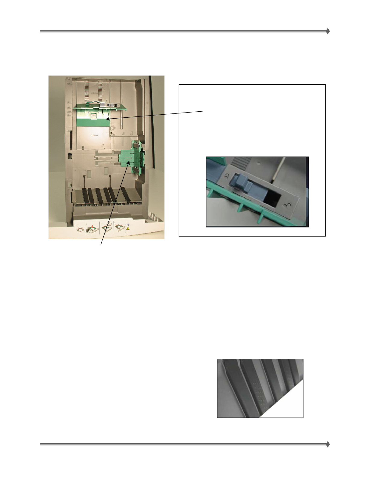
New spring-loaded side guide that enhances feeding & imaging consistency.
• This left side guide helps prevent paper skewing. The spring loaded guide positions itself
to the nearest setting, allowing for imprecise setting of guides.
• Doesn’t have to be reset with every ream. It allows a little forgiveness for
aggressive paper loading.
T65x Paper drawer holds 550 instead of 500. This allows a customer to load a full ream of paper prior to
totally emptying the drawer.
The T65x paper trays have several enhanced
features:
The back guide is easier to move.
There is a rear guide locking system that
ensures consistent sensing & behavior of
the media. It won’t get knocked out of
position. Ships locked according to geo.
Multiple Sheet Feed Prevention
Media occasionally sticks together along the edges when loaded in the Tray. This may cause a multiple
sheet feed or paper jam. Wider restraint pads (on bottom of tray) help with bottom of tray multi-feeds.
Textured Ramps – use the same principals as our
Special Media Tray, causing fewer multi-feeds.
For Training Purposes Only 6/3/2009
8
Page 17
Lexmark T65x and X65x Mono Product Study Guide Rev 1.47
Electrophotographic Process
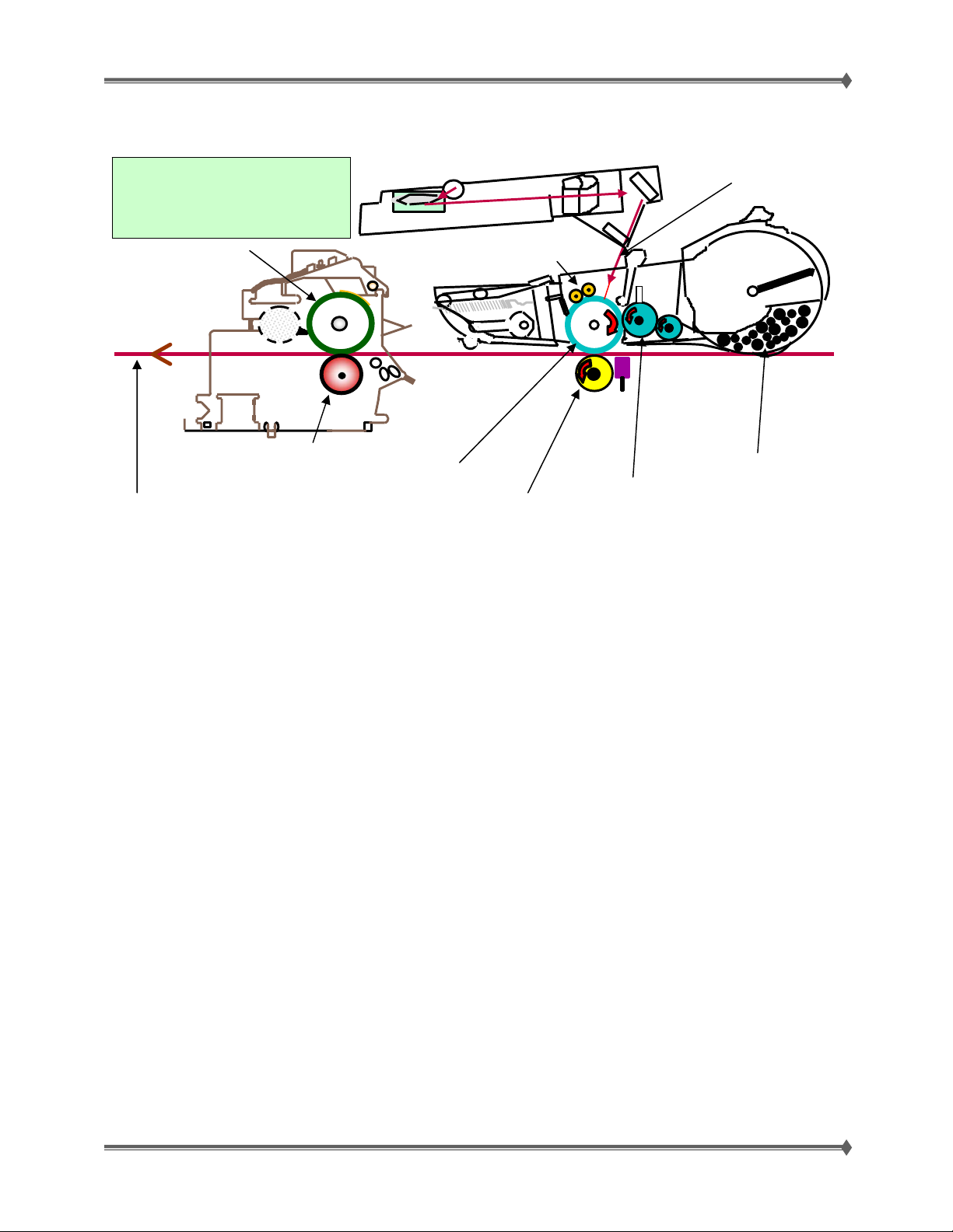
The Photoconductor (PC
drum) plays an active role in
every part of the EP process
with the exception of fusing.
Hot roll
Fuser
Print head
Twin Charge
roller
Laser light
Cartridge
Paper path
Charge:
The twin charge rollers deposit a uniform negative electrostatic charge on the light-sensitive
surface of the photoconductor drum: (also called the PC, Photodeveloper, or OPC).
Exposure:
The printhead generates Laser light that enters the cartridge and strikes the photoconductor
(PC) drum in areas to be developed, forming an invisible (latent) electrostatic image of the
desired print. Note: Any form of light (laser, LED's, sun light, etc.) activates the
Electrophotographic (EP) properties of the drum coating. Consequently, care should be taken to
cover the PC when removed from the printer to protect it from exposure to a light source.
Development:
(Developer Roll) Toner is transferred from the reservoir in the toner cartridge to the
photoconductor drum through electrostatic attraction making the image visible on the PC drum.
Toner is attracted only to areas where the laser imaged the drum. Since the toner and the charge
applied to the drum are both negative, the toner will be repelled from areas where the laser did
not image the drum.
Transfer:
The transfer roll rolls along the underside of the paper to be imaged, and moves the toned
image from the photoconductor to the paper. The toner is negatively charged and the transfer roll
bathes the paper with a positive charge; this attracts the toner to the paper.
Backup roller
PC drum
Transfer roll
Toner
Developer
Fusing:
The paper – now with a “toned” image – moves through the fuser assembly. Using temperature
and pressure, it marries toner to paper.
Cleaning:
Waste toner (toner that was not transferred), paper debris and dust are removed from the
photoconductor drum by the cleaning blade.
For Training Purposes Only 6/3/2009
9
Page 18
Lexmark T65x and X65x Mono Product Study Guide Rev 1.47
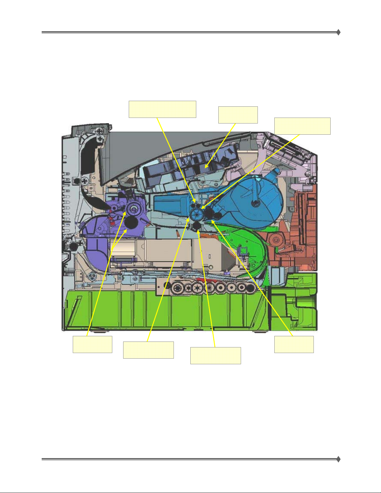
EP (Electrophotographic) Components – T65x Diagram
Twin Charge Rollers
Printhead
Photoconductor
Cleaner Blade
For Training Purposes Only 6/3/2009
Transfer Roller
10
DeveloperFuser Unit
Page 19
Lexmark T65x and X65x Mono Product Study Guide Rev 1.47
Printheads [Oscillating vs. Spinning Polygon Mirror]
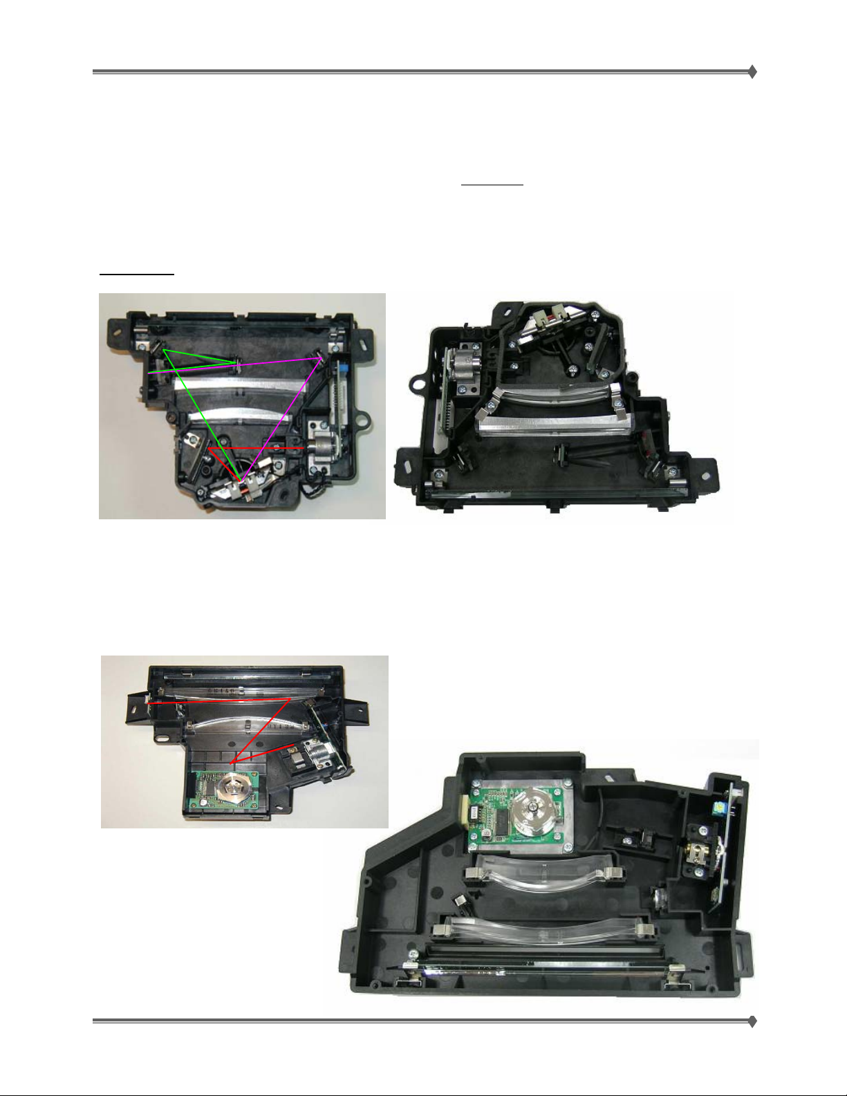
You need to be aware that there are differences in these two types of printheads. Both the alignment
procedures for each type of printhead, as well as the basic diagnostic
has an alignment procedure that is shown in the next section.
T650 & T650n
The T650 & T650n use an oscillating printhead and uses bidirectional printing. This printhead has a
tuning step in addition to the alignment procedure during installation.
steps are different. This printhead
Forward
Reverse
T652dn & T654dn
The T652dn & T654dn use a spinning polygon mirror printhead, as did the T64x. This printhead is 40%
larger than the oscillating printhead and uses unidirectional printing. This printhead has an alignment
procedure that is shown in the next section.
For Training Purposes Only 6/3/2009
11
Page 20
Lexmark T65x and X65x Mono Product Study Guide Rev 1.47
Polygon & Oscillating printhead assembly adjustment
Do the printhead mechanically registration adjustment whenever you remove or replace the printhead or
loosen the mounting screws.
Install the new printhead with the mounting screws centered in the slots in the printhead frame assembly.
Leave the screws loose enough to allow the printhead to move from side to side within the slots. It is
necessary to perform a mechanical registration adjustment before locking down the three printhead
mounting screws.
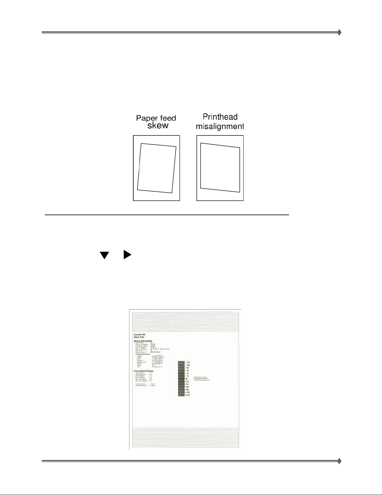
In case of paper feed skew, go to “Alignment assembly – skew adjustment” [Page 15]
To perform the mechanical registration adjustment of the printhead:
1. Turn the printer off.
2. Press and hold
3. Turn the printer on, and release the buttons when Performing Self Test displays.
4. Select Registration from the menu.
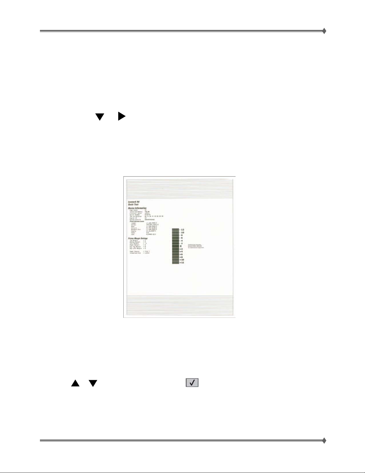
5. Select Quick Test Page. The test page should only be printed on letter or A4 paper from Tray 1. The
Quick Test Page consists of alignment diamonds, horizontal lines that can be used for mechanical
registration adjustment. An example of the printhead alignment printout is shown below:
and to enter the diagnostic mode.
For Training Purposes Only 6/3/2009
12
Page 21

Lexmark T65x and X65x Mono Product Study Guide Rev 1.47
6. Check the Quick Test Page for any sign of misalignment by checking the diamonds at the top left and
top right of the test page for equal distance from the top of the page. If necessary, rotate the
printhead to the left or right and tighten down the mounting screws and check for proper alignment
again by running another Quick Test Page. This procedure may take two or three attempts before you
get satisfactory results.
7. When you have the correct adjustment, ensure that the printhead mounting screws are properly
tightened.
For Training Purposes Only 6/3/2009
13
Page 22
Lexmark T65x and X65x Mono Product Study Guide Rev 1.47
Oscillating printhead assembly electronic adjustment
A step-by-step process to align a new printhead.
Note: Before aligning the printhead electronically, first align the printhead mechanically, if needed. See
“Oscillating printhead assembly adjustment” [on Page 12]
1. Turn the printer off.
2. Press and hold and to enter the diagnostic mode.
3. Turn the printer on, and release the buttons when Performing Self Test displays.
4. Select Registration from the menu.
5. Select Quick Test Page. The test page should only be printed on letter or A4 paper from Tray 1. The
Quick Test Page consists of alignment diamonds, horizontal lines that can be used for skew
adjustment, page count setting, printer serial number code levels, and print registration settings. An
example of the printhead alignment printout is shown below:
6. In the Registration menu, select the Right Margin setting.
7. To determine the margin setting, choose the value that is closest to the darkest bar on the center
graph on the margin page. Add that value to the current right margin setting printed on the left hand
side of the margin page (The right margin setting will also appear on the operator panel di splay under
right margin setting). For example, if the right margin setting on the sheet is -2, and the number that
is closest to the darkest line on the graph is 3, the you would enter (-2+3=+1) The new right margin
setting on the op. panel should now equal +1.
8. Press
9. Print the Quick Test page again and check that the darkest line in the center graph is equal to zero. If
it is, then check to see if the left, top, and bottom margins are detected. If it is not, then repeat step 7.
For Training Purposes Only 6/3/2009
or to the desired setting, and press .
Note: The alignment of the left margin positions the black plane to the right or left. The alignment
of the right margin does not alter the margins and should only be used to adjust the printhead.
14
Page 23
Lexmark T65x and X65x Mono Product Study Guide Rev 1.47
Alignment assembly – skew adjustment
Do the alignment assembly adjustment whenever you replace the alignment assembly. Always print a
copy of the Quick Test Page before making any adjustments to the alignment assembly reference
adjustment screw. When replacing the alignment assembly, it is necessary to back the reference
adjustment screw out far enough to remove the old assembly and install the new one.
• If you are replacing the alignment assembly, go to step A.
• If you are only adjusting the reference adjustment screw, go to step B.
Step A
Print a copy of the Quick Test Page and check the margin adjustments printed on the test page. These
settings should be within the range specified in “REGISTRATION” shown below:
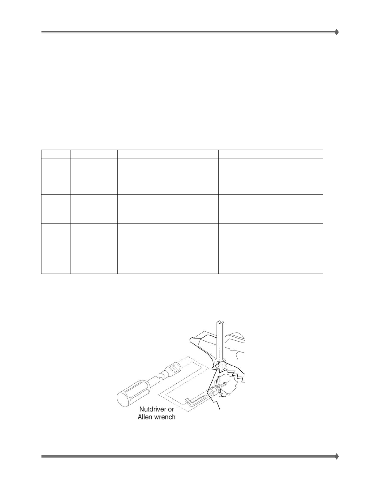
Variable Description Value Direction of change
T= Top margin -25 to +25 Each increment causes
approximately 4 pels shift (at 600
dpi).
B= Bottom margin -20 to +20 Each increment causes
approximately 0.55 mm shift in the
bottom margin.
L= Left margin - -25 to +25 A positive change moves the image
M= Right margin - 99 to +99 A positive change moves the image
Do the reference adjustment if you are sure the margins are set correctly.
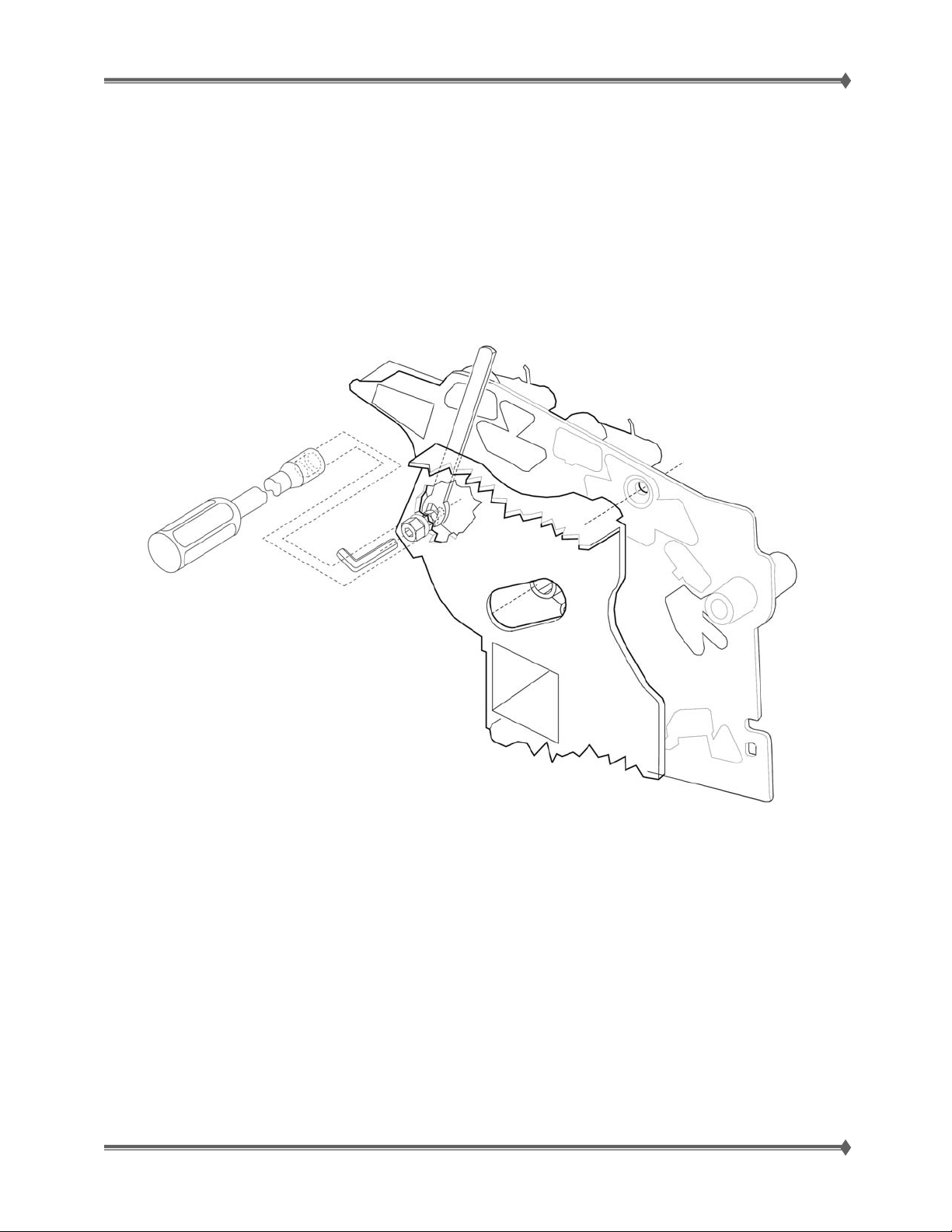
1. Loosen the locknut on the inside rear of the alignment assembly.
2. Remove the two screws holding the alignment assembly to the left side frame.
3. Back the reference adjustment screw out far enough to allow the alignment assembly to be removed
from the printer. It is not necessary to completely remove the screw.
4. Install the new alignment assembly. Turn the reference screw clockwise with a 7 mm nut driver or M3
Allen wrench until it touches the back of the reference plate, and tighten the nut with a 5.5 mm
wrench.
A positive change moves the image
down the page and increases the
top margin. A negative change
moves the image up and decreases
the top margin.
A positive change compresses the
image so it appears to move down
the page and a negative change
moves the image up.
to the right, and a negative change
moves the image to the left. No
compression occurs.
to the right, and a negative change
moves the image to the left.
For Training Purposes Only 6/3/2009
15
Page 24
Lexmark T65x and X65x Mono Product Study Guide Rev 1.47
The reference adjustment screw can be adjusted without loosening the nut. Turn the screw clockwise a
few turns and print a copy of the Quick Test Page as you check the diamonds on the left margin.
Continue adjusting the screw as you check the results of each adjustment on a new test page until you
obtain the results you want.
Step B
Print a copy of the Quick Test Page, and check the margin adjustments printed on the test page. These
settings should be within the range specified in “REGISTRATION” sho wn in chart in section A above.
The reference screw can be adjusted without loosening the locknut. Turn the screw a few t urns, and print
a copy of the Quick Test Page as you check the diamonds on the left margin. Continue adjusting the
screw as you check the results of each adjustment on a new test page until you obtain the results you
want.
For Training Purposes Only 6/3/2009
16
Page 25
Lexmark T65x and X65x Mono Product Study Guide Rev 1.47
Document Scanning
Document scanning at ADF
The document scanning section of this machine consists of a scanner that reads a single-sheet document
placed on the platen glass and a document feeder that can transport a multiple-sheet document for one
or two sided scanning.
Document scanning at platen
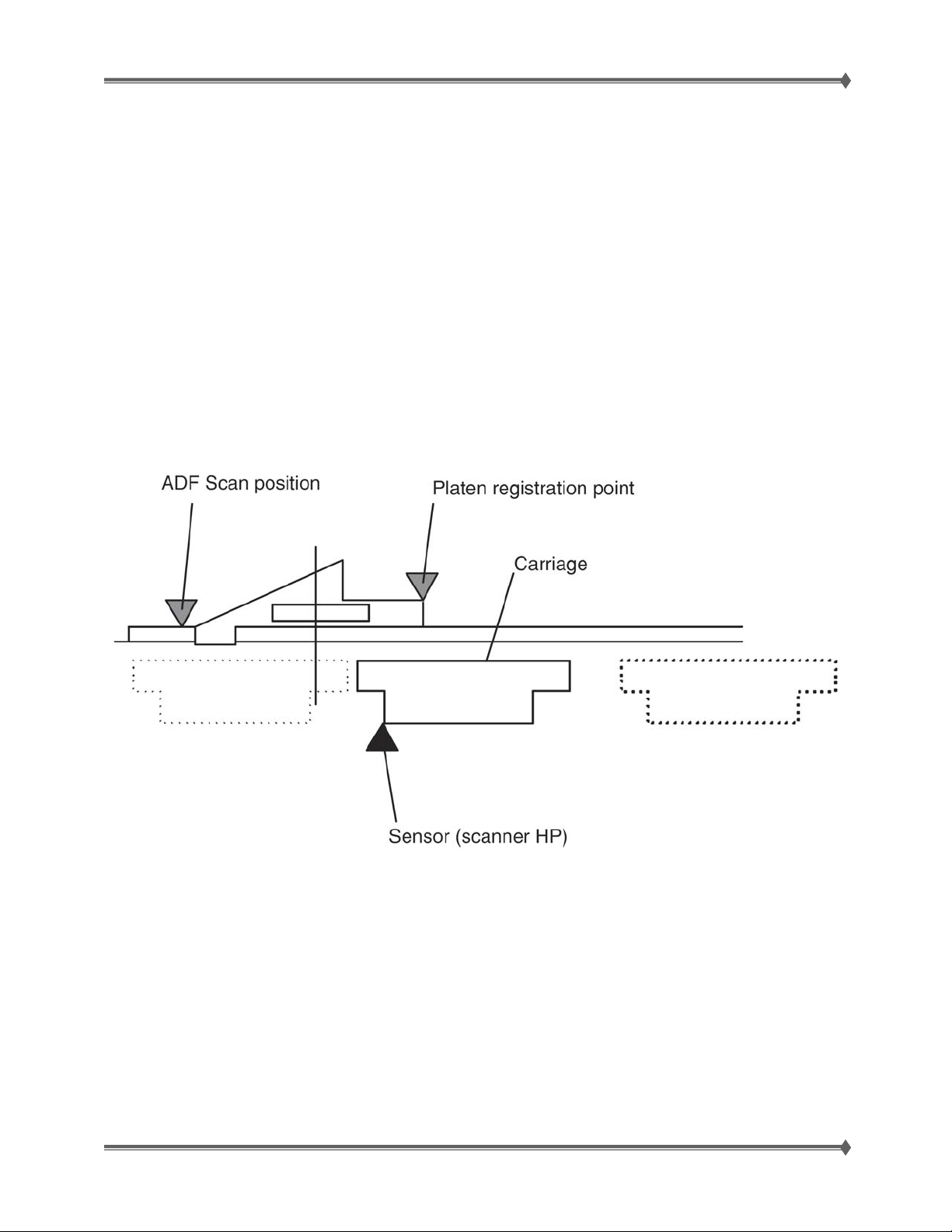
Shown below is the operational overview of document scanning at the platen.
The scanner CCD assembly travels to read the document.
The exposure lamp is installed on the scanner CCD assembly. As the scanner CCD assembly travels, the
document on the platen glass is scanned and exposed with the exposure lamp.
The image data is read with the scanner CCD image sensor assembly.
This ADF employs a constant velocity transport system that scans images by feeding the document at a
constant speed over the specified position (scan position) where the carriage of the scanner unit
assembly is fixed.
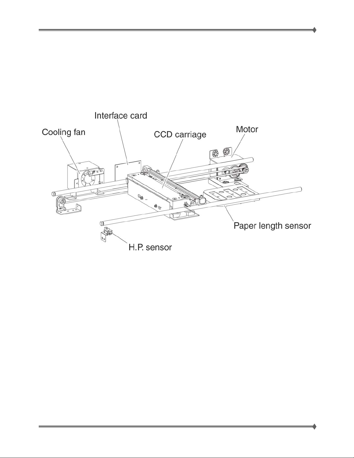
Names and functions of components
The sections below describe the functions of main components of the scanner.
Flatbed (FB) Scanner unit assembly – [APS; automatic paper sensor]
Sensor (FB length APS 1), Sensor (FB length APS 2), Sensor (FB length APS 3)
The document length in the slow scanning direction is detected by a combination of the three
reflector sensors.
Switch (ADF closed interlock)
A switch that detects whether the ADF is open and determines the timing of platen document size
detection.
Scanner drive motor assembly
A stepping motor that drives the scanner CCD assembly.
For Training Purposes Only 6/3/2009
17
Page 26
Lexmark T65x and X65x Mono Product Study Guide Rev 1.47
Sensor (FB scanner HP [home position])
A sensor that detects the HP position of the flatbed scanner CCD assembly.
Scanner exposure lamp
A xenon lamp to which the document is exposed.
Scanner controller card assembly
A card that controls the scanner section.
Scanner cooling fan
A fan that prevents overheating of the scanner controller card assembly and exposu re lamp.
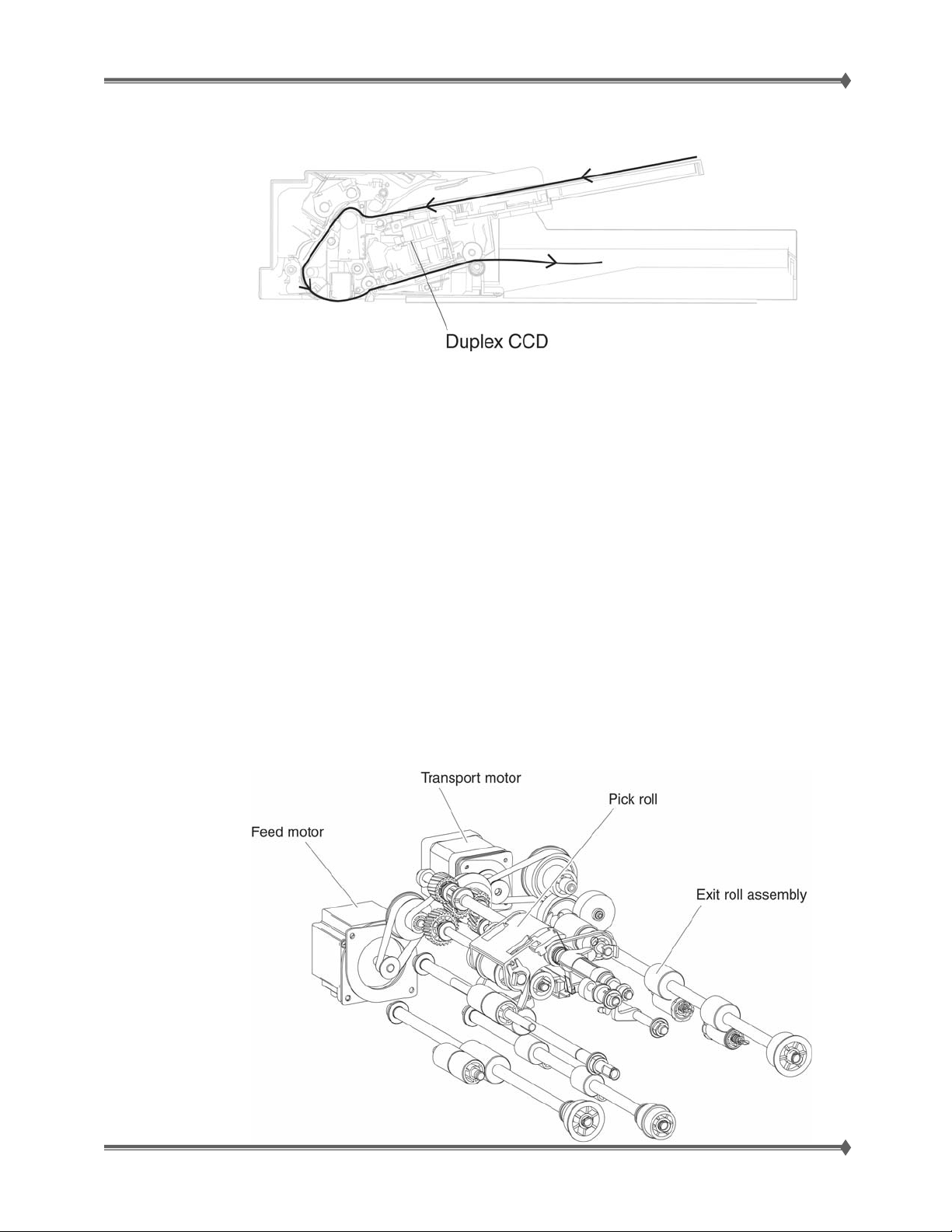
A document sheet set in the document tray assembly is fed through the ADF feed roll, ADF pick roll, and
ADF separation roll assembly. The document image is scanned at the scan position, and the document
sheet is ejected through the ADF feed-out roll assembly and the ADF exit roll assembly. For a duplex
document sheet, the image on side 1 and the image on side 2 are scanned at the same time in the same
pass.
Described below is the overview of the steps before document scanning and that of simplex and duplex
document scanning modes.
Setting a document
When a document is set on the document tray assembly and the lead edge is pushed into the tray until it
stops, the ADF document set actuator moves to place the sensor (ADF document set) in the unshielded
(unblocked) state. Then the machine recognizes that the document has been set properly, turning on the
document set LED.
Preparation for feed
Pressing the start button with the document set in the document tray will start feeding the document.
First the pick roll moves down and presses the document on the document tray to enable do cument feed.
The pick roll moves down with the normal rotation of the ADF feed drive motor assembly and it moves up
with the reverse rotation of the ADF feed drive motor assembly.
Upon completion of document feed, the pick roll returns to the normal (raised) position.
For Training Purposes Only 6/3/2009
18
Page 27
Lexmark T65x and X65x Mono Product Study Guide Rev 1.47
Document feed path from the ADF
Shown below is the document feed path from the ADF.
Simplex and duplex document feed
For two simplex document sheets, feed is performed in the following sequence:
1. The first document sheet is fed to the ADF transport roll assembly.
2. The document is fed to the ADF registration roll assembly, and then fed to the scan feed
reference position.
3. The document sheet is fed at the feed speed corresponding to the selected magnification, and
the image on it is scanned with the exposure lamp at the scan position.
4. As the image is scanned, the document sheet is fed and ejected by the ADF feed-out roll
assembly and ADF exit roll assembly that are driven by the ADF transport motor.
5. When the trail edge of the first document sheet has passed through the sensor (sheet through),
the feed of the second document sheet starts.
Duplex document
For duplex document sheets, feed is performed in the following sequence:
1. The first document sheet is fed to the ADF transport roll assembly.
2. The document is fed to the ADF registration roll assembly, and then fed to the scan feed
reference position.
3. The document sheet is fed at the feed speed corresponding to the selected magnification, and
the image on it is scanned with the exposure lamp at the scan position.
4. As the image is scanned on both sides, the document sheet is fed and ejected by the ADF
feed-out roll assembly and ADF exit roll assembly that are driven by the ADF transport motor.
For Training Purposes Only 6/3/2009
19
Page 28
Lexmark T65x and X65x Mono Product Study Guide Rev 1.47
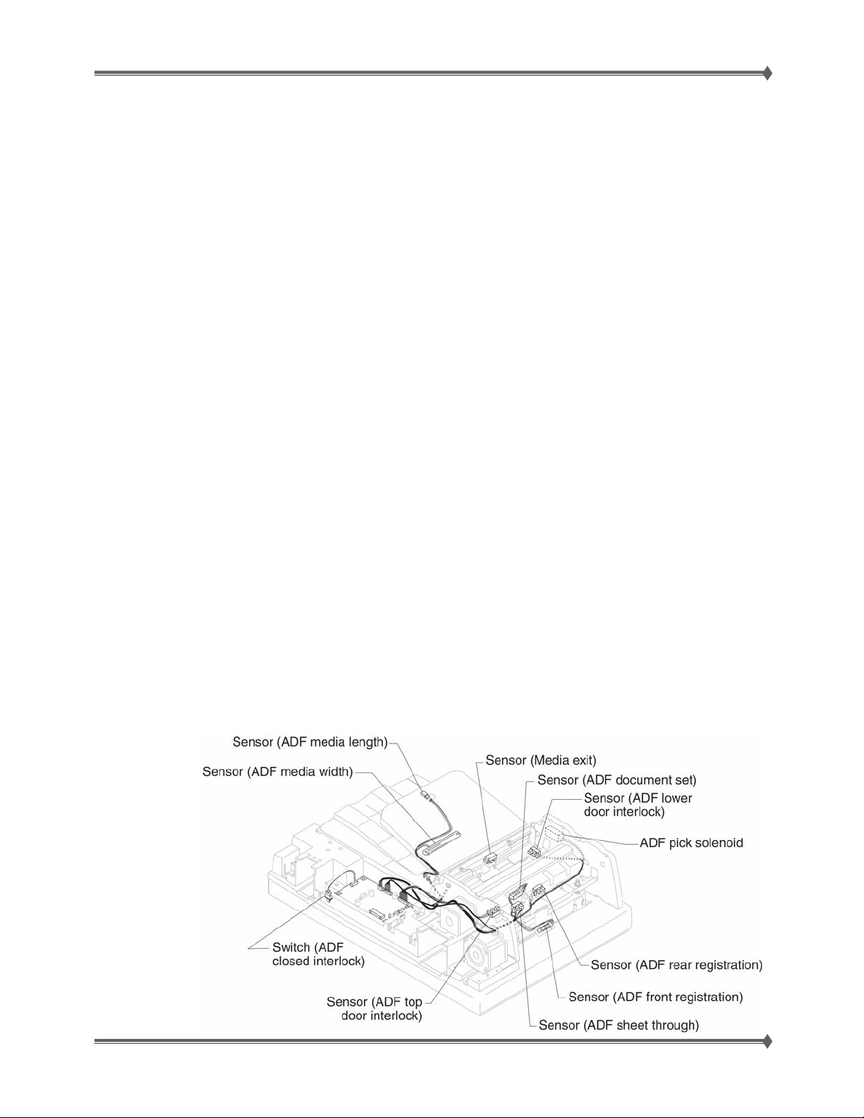
Names and functions of components
ADF
Sensor (ADF long media)
The document length in the slow scanning direction is detected by this sensor.
Sensor (ADF width 1), Sensor (ADF width 2), Sensor (ADF width 3), Sensor (ADF width 3)
The document length in the fast scanning direction is detected by the combination of these three
sensors detecting the position of the tray on which the document is set.
Sensor (ADF document set)
A sensor that detects the presence or absence of a document on the ADF document tray.
ADF Document Set LED
An LED that illuminates when a document is set on the ADF Document Tray.
Switch (ADF top door interlock)
A switch that detects whether the ADF top door assembly is open.
ADF controller card assembly
A card that controls the ADF unit assembly. The ADF controller card assembly is connected to
and controlled by the Scanner controller card assembly.
Sensor (ADF sheet through)
The ADF sensor (ADF sheet through) is installed immediately downstream from the Feed/pick roll
assembly to detect completion of document feed.
Sensor (ADF 1st scan)
The ADF sensor (ADF 1st scan) is installed just upstream of the scanning surface and is used to
for scanning timing operations.
Sensor (2nd scan)
The ADF sensor (ADF 1st scan) is installed just down stream of the scanning surface and is u sed
to for scanning timing operations.
Sensor (ADF media exit)
The sensor (ADF media exit) is used to detect when scanned media has exited the ADF.
ADF feed motor assembly
The feed motor assembly is a stepping motor that rotates the pick roll and feed roll in the reverse
direction (CCW direction) and rotates the ADF transport roll assembly in the normal direction (CW
direction).
When this motor rotates in the reverse direction, the ADF transport roll assembly stops.
ADF transport motor
The ADF transport motor is a stepping motor that rotates the ADF registration roll assembly, ADF
feed-out roll assembly, and ADF exit roll assembly.
ADF pick solenoid assembly
This solenoid causes the ADF pick roll to be raised and lowered in order to properly pick the
media.
For Training Purposes Only 6/3/2009
20
Page 29
Lexmark T65x and X65x Mono Product Study Guide Rev 1.47
Scanner Manual Registration
To perform the Scanner Manual Registration:
1. Touch
The panel displays the following headers:
2. Touch Print Quick Test to print a registration page.
3. Choose the section of the scanner to align.
To align the scanner glass (flatbed):
Repeat the ADF alignment steps until the position on the page of the Quick Test copy closely matches
the original.
Touch Back to cancel and return to the Configuration Menu
to select Scanner Manual Registration from the Configuration Menu.
• Print Quick Test
• Copy Quick Test
• Flatbed
a. Place the Quick Test page facedown on the scanner glass.
b. Touch Copy Quick Test. The scanner prints a copy of the Quick Test page.
c. Touch Flatbed.
d. Use the copy of the Quick Test page to adju st the Left Margin an d Top Margin settings.
e. Touch Submit.
f. Touch Copy Quick Test and compare the new copy to the original. Repeat the flatbed
alignment steps until the position on the page of the Quick Test copy closely matches the
original.
To align the ADF:
a. Do one of the following:
• To align the ADF front: place the Quick Test page faceup, short edge first into the
ADF.
• To align the ADF back: place the Quick Test page facedown, short edge first into the
ADF.
b. Touch Copy Quick Test. The scanner prints a copy of the Quick Test page.
c. Touch ADF Front or ADF Back.
d. Use the copy of the Quick Test page to adjust the Horizontal Adjust and Top Margin
settings.
e. Touch Submit.
f. Touch Copy Quick Test and compare the new copy to the original.
For Training Purposes Only 6/3/2009
21
Page 30
Lexmark T65x and X65x Mono Product Study Guide Rev 1.47
Operator Panels
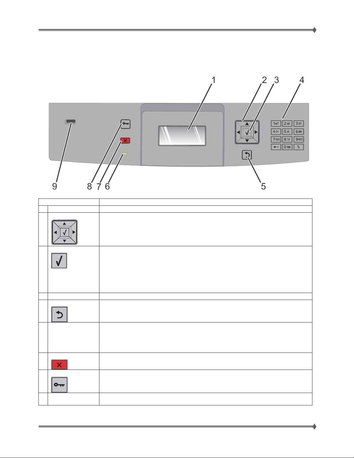
T65x Panel Buttons
Item Description
1 Display Shows messages and pictures that communicate the status of the printer.
2 Navigation button
Press the up or down arrow buttons to scroll through menus or menu items, or to
increase or decrease a value when entering numbers.
Press the left or right arrow buttons to scroll through menu settings (also called
3 Select
values or options), or to scroll through text that rolls to another screen.
• Opens a menu item and displays the available values or settings. The current
setting is indicated by an asterisk (*).
• Saves a displayed menu item as the new user default setting.
Note: When a new setting is saved as the user default setting, it remains in effect
until a new setting is saved or until factory defaults are restored.
Note: Settings chosen from a software program can also change or override the
user default settings selected from the printer control panel.
4 Keypad Enter numbers or symbols on the display.
5 Back
Returns the display to the previous screen.
6 Indicator Light
7 Stop
Indicates the printer status:
• Off–The power is off.
• Blinking green–The printer is warming up, processing data, or printing.
• Solid green–The printer is on, but idle.
• Solid red–Operator intervention is needed.
Stops all printer activity.
A list of options is offered once Stopped appears on the display.
8 Menu
Opens the menu index
Note: The menus are available only when the printer is in the
Ready state.
9 USB
Insert a flash drive into the front of the printer to print saved files.
Note: Only the front USB port supports flash drives.
For Training Purposes Only 6/3/2009
22
Page 31
Lexmark T65x and X65x Mono Product Study Guide Rev 1.47
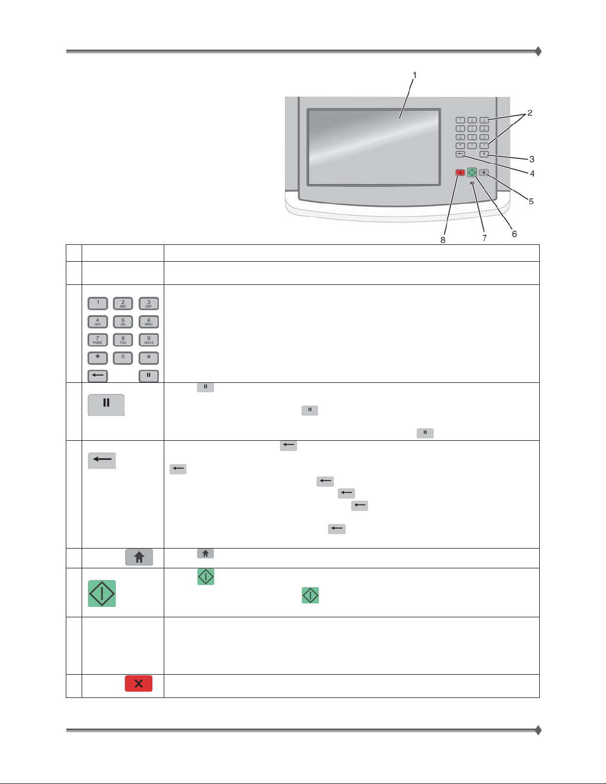
Understanding the X65x Printer Control Panel
Item Description
1 Display View scanning, copying, faxing, and printing options as well as status and error
messages.
2 Keypad
Enter numbers or symbols on the display.
3 Dial Pause
4 Back
5
Home
6 Start
7 Indicator light Indicates the printer status:
8
Stop
Press
To field, a Dial Pause is represented by a comma (,).
From the home screen, press
The button functions only within the Fax menu or with fax functions. When outside
of the Fax menu, fax function, or home screen, pressing
In the Copy menu, press
Count. The default value of 1 appears if the entire number is deleted by pressing
In the Fax Destination List, press
entered manually. You can also press
an entire line is deleted, another press of
line.
In the E-mail Destination List, press
cursor. If the character is in a shortcut, then the shortcut is deleted.
Press
Press
From the home screen, press
If pressed while a job is scanning, the button has no effect.
Off – The power is off.
Blinking green – The printer is warming up, processing data, or printing.
Solid green – The printer is on, but idle.
Blinking red – Operator intervention is needed.
Stops all printer activity
A list of options is offered once Stopped appears on the display.
to cause a two- or three-second dial pause in a fax number. In the Fax
numerous times.
to return to the home screen.
to initiate the current job indicated on the display.
to redial a fax number.
causes an error beep.
to delete the right-most digit of the value in the Copy
to delete the right-most digit of a number
to delete an entire shortcut entry. Once
causes the cursor to move up one
to delete the character to the left of the
to start a copy job with the default settings.
For Training Purposes Only 6/3/2009
23
Page 32
Lexmark T65x and X65x Mono Product Study Guide Rev 1.47
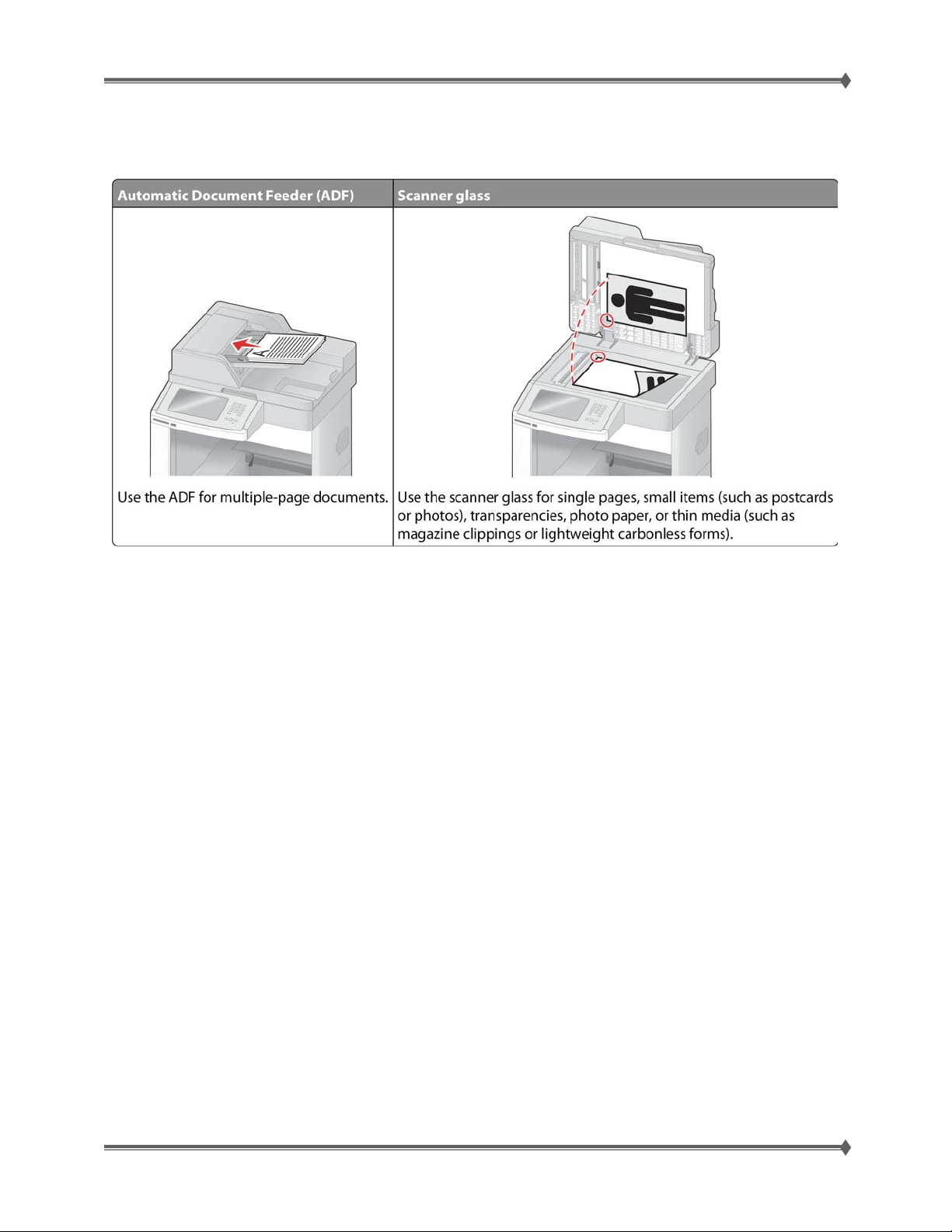
Understanding the ADF (automatic document feed) & Scanner Glass
You can use the ADF or the scanner glass to scan documents.
Using the ADF
The Automatic Document Feeder (ADF) can scan multiple pages, including dupl ex pages. When using
the ADF:
• Load the document into the ADF face up, short edge first.
• Load up to 75 sheets of plain paper in the ADF input tray.
• Scan sizes from 76.2 x 139.4 mm (3.0 x 5.5 in.) to 215.9 x 355.6 mm (8.5 x 14 in.).
• Scan documents with mixed page sizes (letter and legal).
• Scan media weights from 52 to 120 g/m2 (14 to 32 lb).
• Do not load postcards, photos, small items, transparencies, photo paper, or thin media (such as
magazine clippings) into the ADF. Place these items on the scanner glass.
Using the scanner glass
The scanner glass can be used to scan or copy single pages or book pages. When using the scanner
glass:
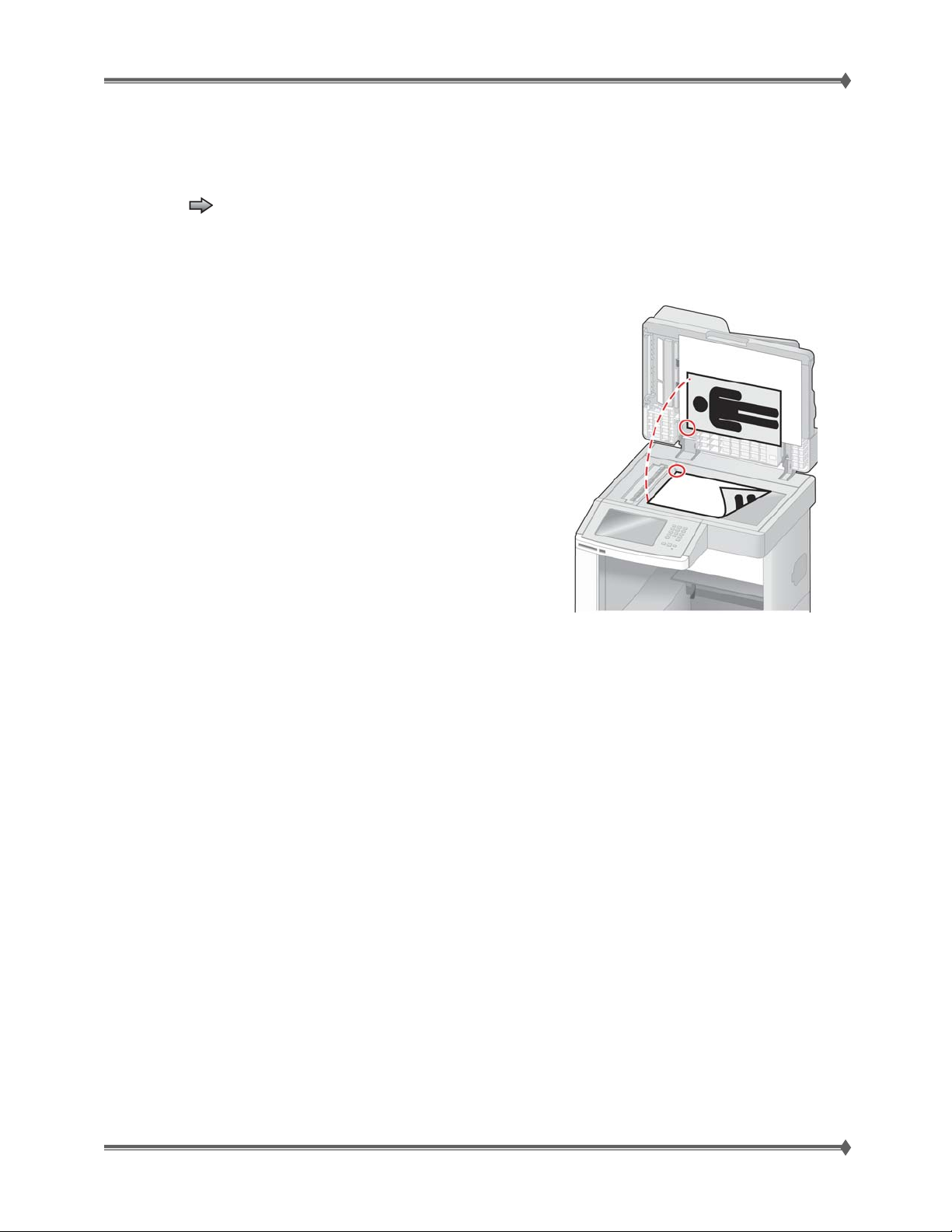
• Place a document facedown on the scanner glass in the upper left corner.
• Scan or copy documents up to 215.9 x 355.6 mm (8.5 x 14 in.).
• Copy books up to 25.3 mm (1 in.) thick.
NOTE: If there is a defect that appears on the same place on every printed page, cleaning the scanner
glass is always the first step that should be taken to eliminate the problem.
For Training Purposes Only 6/3/2009
24
Page 33
Lexmark T65x and X65x Mono Product Study Guide Rev 1.47
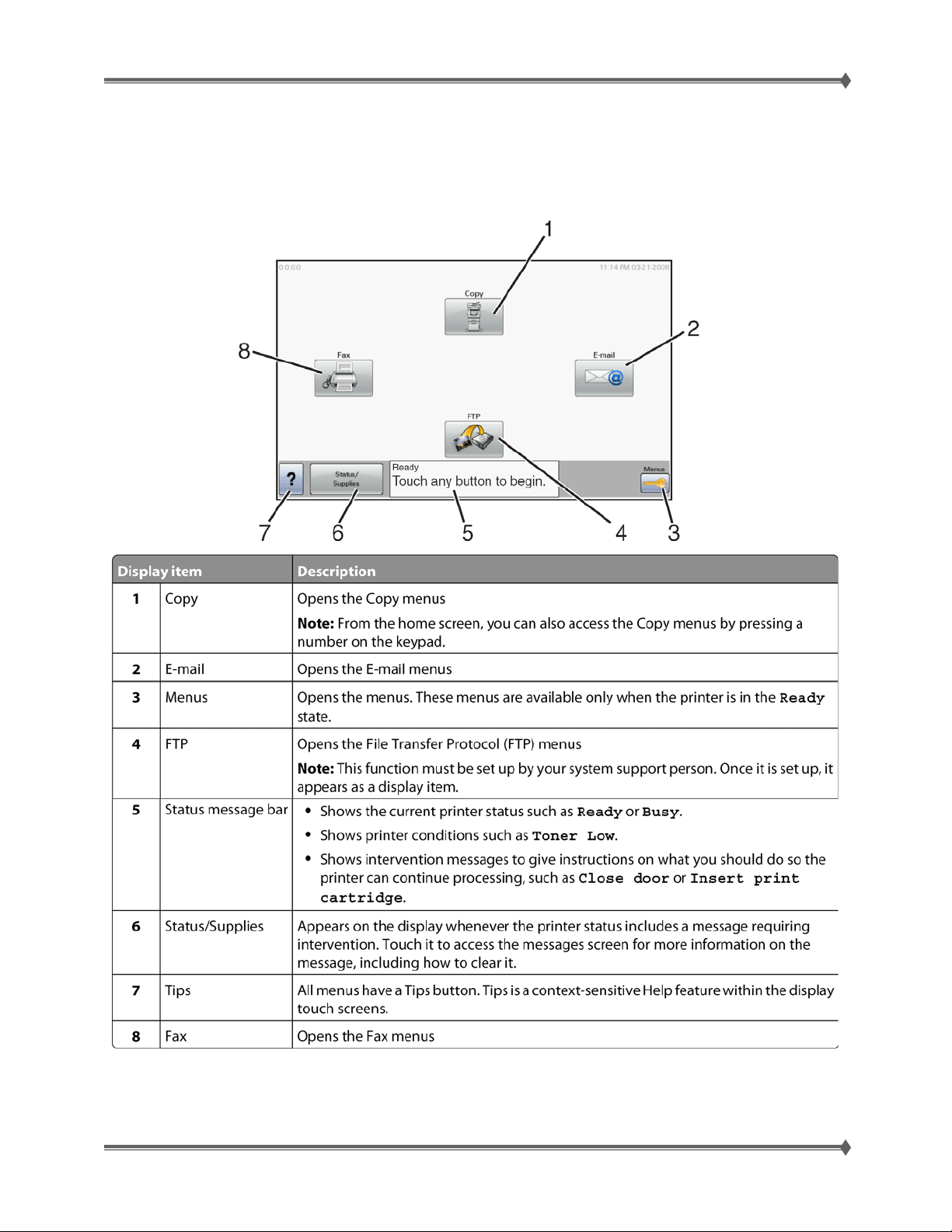
Understanding the home screen
After the printer is turned on and a short warm-up period occurs, the display shows the following basic
screen which is referred to as the home screen. Use the home screen buttons to initiate an action such as
copying, faxing, or scanning; to open the menu screen; or to respond to messages.
For Training Purposes Only 6/3/2009
25
Page 34
Lexmark T65x and X65x Mono Product Study Guide Rev 1.47
Customer Menus
For a complete listing of the printer menu tree, consult the User’s Guide. The menus most commonly
accessed are highlighted in blue.
Paper Menu
Default Source
Paper Size/Type
Configure MP
Envelope Enhance
Substitute Size
Paper Texture
Paper Weight
Paper Loading
Custom Types
Universal Setup
Bin Setup
1
Depending on the printer setup, this menu item appears as Network Setup Page or Network <x> Setup
Page.
2
Depending on the printer setup, this menu item appears as Standard Network or Network <x>.
Security
Miscellaneous
Security Settings
Confidential Print
Disk Wiping
Security Audit Log
Set Date/Time
Reports
Menu Settings Page
Device Statistics
Network Setup Page
Profiles List
NetWare Setup Page
Print Fonts
Print Directory
Asset Report
Settings
General Settings
Setup Menu
Finishing Menu
Quality Menu
Utilities Menu
XPS Menu
PDF Menu
PostScript Menu
PCL Emul Menu
HTML Menu
Image Menu
Flash Drive Menu
Network/Ports
Active NIC
1
Standard Network
Standard USB
Parallel <x>
Serial <x>
SMTP Setup
Help
Print All
Print Quality
Printing Guide
Media Guide
Print Defects
Menu Map
Information Guide
Connection Guide
Moving Guide
Supplies Guide
2
For Training Purposes Only 6/3/2009
26
Page 35

Lexmark T65x and X65x Mono Product Study Guide Rev 1.47
Service Mode
Confirm the installation status
Be sure to check the following items before starting the troubleshooting procedures.
• With the power cord unplugged from the wall outlet, check that the cord is free from breakage,
short-circuit, disconnected wire, or incorrect connection in the power cord.
• The printer is properly grounded. Check the power cord ground terminal.
• The printer is not installed at a place subjected to extreme temperature, extreme humidity or
rapid changes in temperature.
• The printer is not installed close to water service, humidifier, heat generating unit, fire, in a very
dusty place, or a place exposed to air flow from the air conditioning system.
• The printer is not installed in a place where volatile gas or inflammable gas is generated.
• The printer is not installed in direct sun.
• The printer is installed on a level and stable surface.
• Media meets specifications and is installed properly.
• Customer maintenance parts have been replaced at the specified intervals.
• Check all attached options for proper attachment and electrical connection.
• Refer to the User’s Guide for proper installation.
Power-on Reset sequence
The following is an example of the events that occur during the POR sequence:
1. Turn the machine on.
2. The Lexmark splash screen appears with a progress bar in the center until the code is loaded.
3. The fuser cooling fan turns on.
4. The fuser unit assembly lamps turn on.
5. The system card assembly cooling fan turns on.
6. Operator panel LED becomes solid.
7. The transport motor turns on.
Entering Diagnostics mode on the T65x
1. Press and hold and .
2. Turn on the printer.
3. Release the buttons after ten seconds.
NOTE: Powering up in diagnostic mode allows the technician to test the machine (using a generic
FRU) and then remove the generic FRU, if the FRU did not fix the problem. The generic FRU will
mirror and lock during a standard POR.
For a complete listing of the printer menu tree, consult the Service Manual.
For Training Purposes Only 6/3/2009
27
Page 36

Lexmark T65x and X65x Mono Product Study Guide Rev 1.47
Accessing service menus on the X65x
There are different test menus that can be accessed during POR to identify problems with the printer.
Diagnostics
Menu
Configuration
Menu
1. Turn off the printer.
2. Press and hold the 3 and 6 buttons
simultaneously for about 10 seconds.
3. Turn on the printer.
4. Release the buttons after 10 seconds.
1. Turn off the printer.
2. Press and hold the 2 and 6 buttons
simultaneously for about 10 seconds.
3. Turn on the printer.
4. Release the buttons after 10 seconds.
The Diagnostics Menu group
consists of menus, settings, and
operations that are used to
diagnose various printer
problems.
Note: While the Diagnostics
menu group is active, all host
interfaces are offline.
The Configuration Menu group
contains a set of menus, settings,
and operations which are
infrequently required by a user.
Generally, the options made
available in this menu group are
used to configure a printer for
operation.
Accessing SE menu on the X65xe MFP and T65x printer
SE menu on the T65x 1. Press Menu
2. Select Network/Ports
3. Select Standard Network
4. Select Standard Network Setup
5. Press left arrow, select and right arrow to enter SE menu
SE menu on the X65xe MFP 1. Press Menu
2. Select Network/Ports
3. Select Standard Network
4. Select Standard Network Setup
5. Press 9,7,6 at the same time to enter the SE menu
Mirrored MVRAM
• Powering up in diagnostic mode allows the technician to test the machine and then rem ove the
generic
• NVRAM is mirrored in 2 different places:
If the repair requires replacing multiple NVRAM components; replace one at a time with POR in between.
FRU, if the FRU did not fix the problem.
o operator panel
o system board.
Print Quality Diagnostics
Print quality can be very subjective. Be certain to get samples whenever possible of what the customer
believes to be the problem. Run your own print samples to verify the problem, and check to make certain
that appropriate the paper media that is being used in the printer before you start.
For Training Purposes Only 6/3/2009
28
Page 37
Lexmark T65x and X65x Mono Product Study Guide Rev 1.47
Print quality pages (Prt Quality Pgs)
The print quality test pages can be printed from either the Diagnostics mode or Configuration Menu
(CONFIG MENU). When printed from the Diagnostic mode, additional information is included, and the
print cartridge lockout is bypassed.
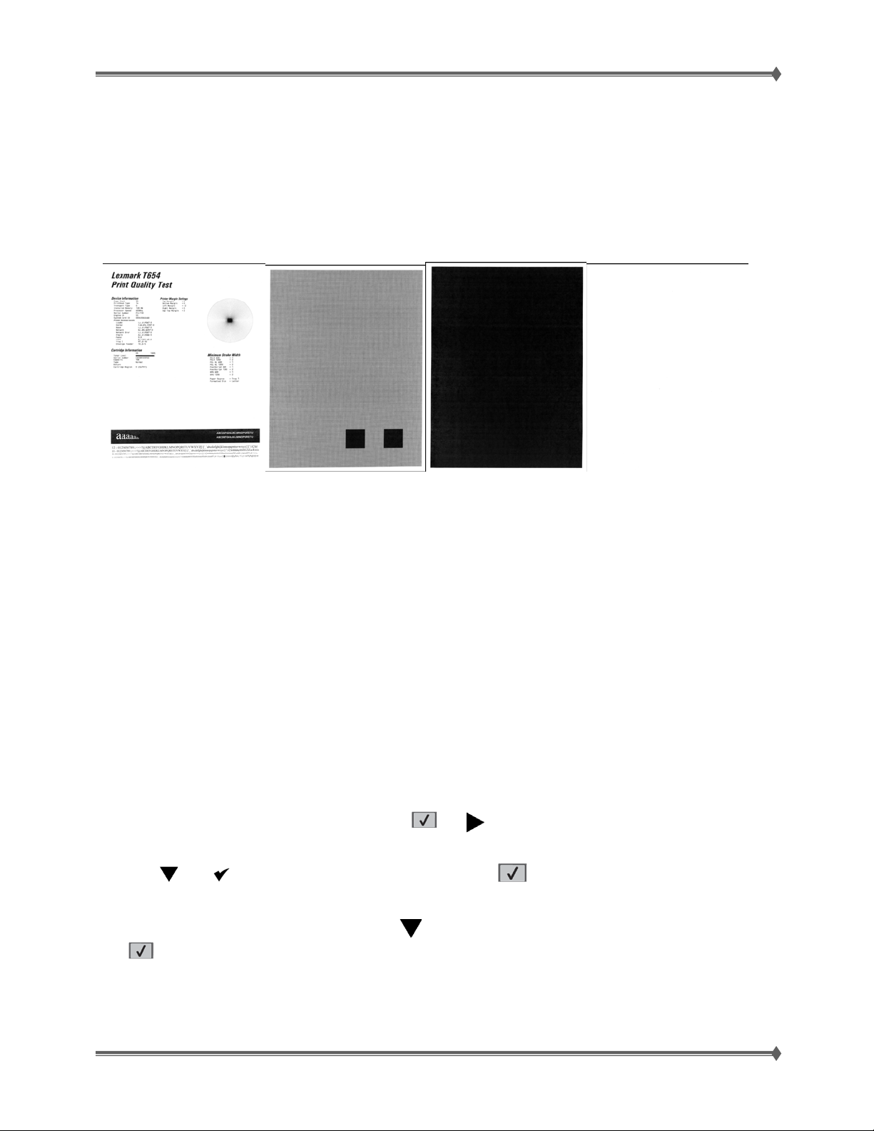
The print quality pages consist of four pages. Page one contains a mixture of graphics and text. Page two
is gray with two one inch black squares located on the bottom right. Page three is solid black page and
page four is blank. If duplex is turned on, the pages are duplexed. The Print Quality Test pages are
printed in English and must always be printed on letter, legal, or A4 paper.
To run the Print Quality Test Pages, select Prt Quality Pgs from PRINT TESTS. The message Printing
Quality Test Pages is displayed.
The following is included in the DIAGNOSTICS version of the first print quality test page:
• Device information
• Printer revision levers
• Carterie information
• Printer margin settings
• EP setup
• Printer setup
• Minimum stroke width
Note: The print quality test pages can also be printed from the Configuration menu (CONFIG MENU),
however a cartridge must be installed with a machine class ID matching the machine class ID stored in
NVRAM. The CONFIG MENU print quality test pages are identical to the DIAGNOSTIC print quality test
pages with the exception of the first page. The first print quality test page from the CONFIG MENU does
not include EP or Printer setup.
Isolating print quality problems
To help isolate print quality problems, get a printout “sample” as a base, print the print quality test pages:
1. Turn the printer off.
2. From the printer control panel, press and hold
3. Release both buttons when Performing Self Test appears. The printer performs its power-on
sequence, and then Config Menu appears.
4. Press
The pages are formatted, Printing Quality Test Pages appears, and then the pages print. The
message remains on the printer control panel display until all the pages print.
5. After the print quality test pages print, press
The information in the following topics may help you solve print quality problems. If these suggestions still
do not correct the problem, you may have a printer part that requires adjustment or replacement.
until Prt Quality Pgs appears, and then press .
.
and while turning the printer on.
until ExitConfig Menu appears, and then press
For Training Purposes Only 6/3/2009
29
Page 38
Lexmark T65x and X65x Mono Product Study Guide Rev 1.47
ONCE YOU HAVE CHECKED THE ITEMS AS SUGGESTED BELOW, TAKEN THE ACTION
SUGGESTED,AND RESEATED OR REINSTALLED THE ITEM CORRECTLY, IF THE PROBLEM STILL
PERSISTS: REPLACE THE ITEM
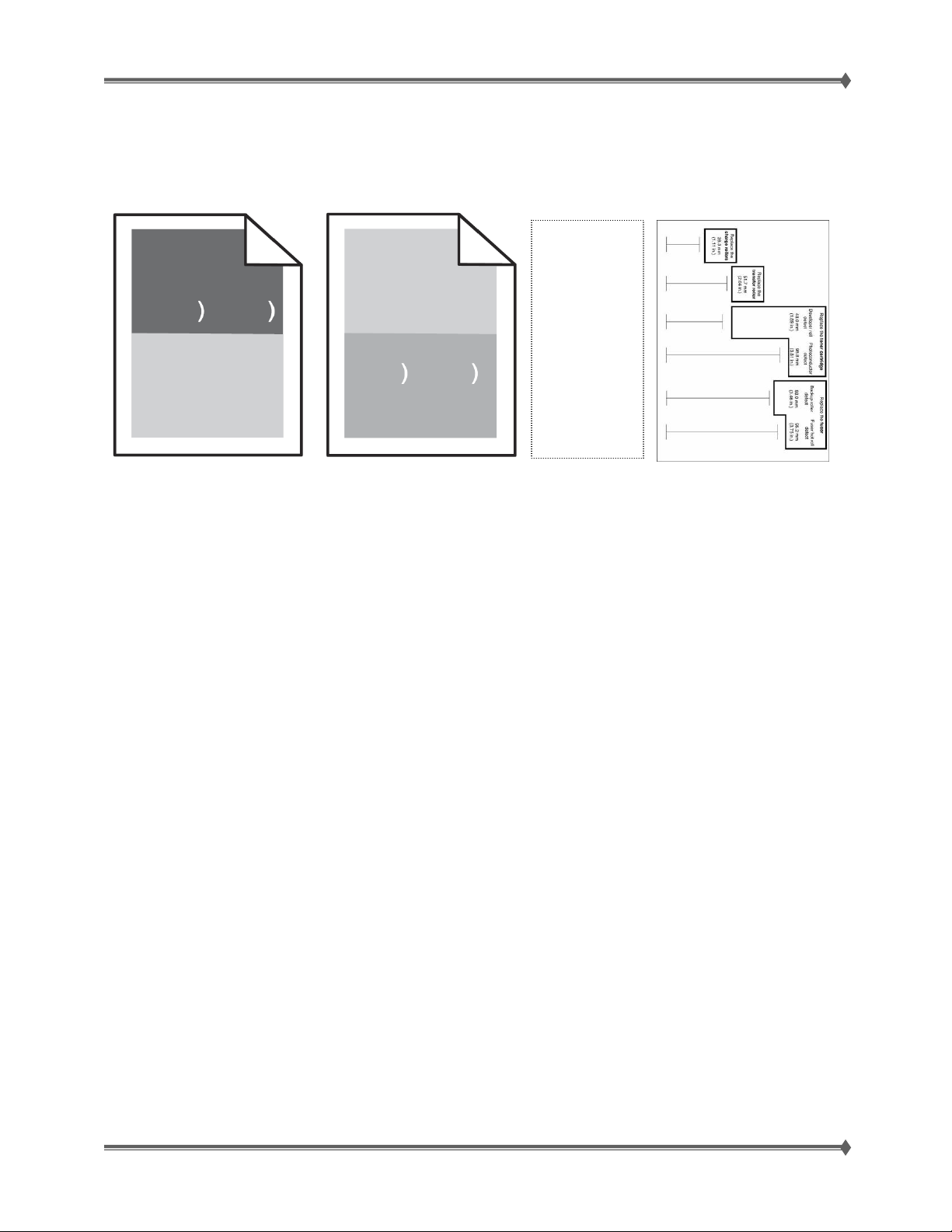
Repeating defects
Print out and
use this
Print
Defects
Page - - - >
to visually
determine
what
component
may be
causing the
print defect.
REPEATING MARKS OCCUR EVENLY DOWN THE PAGER
Replace the charge rolls if the defects occur every 28.3 mm (1.11 in.).
Replace the transfer roller if the defects occur every 51.7 mm (2.04 in.).
Replace the print cartridge if the defects occur every:
• 47.8 mm (1.88 in.)
•
96.8 mm (3.81 in.)
Replace the fuser if the defects occur every:
• 88.0 mm (3.46 in.)
•
95.2 mm (3.75 in.)
For Training Purposes Only 6/3/2009
30
Page 39

Lexmark T65x and X65x Mono Product Study Guide Rev 1.47
Solid Black
Before starting, check the media route (paper
path) for foreign objects, such as staples, clips,
paper scraps, etc in the media path.
CHECK THE CHARGE ROLL ASSEMBLY TO BE CERTAIN THAT IT IS INSTALLED CORRECTLY.
If the component seems to be installed correctly, replace the charge roll assembly.
CHECK THE TONER CARTRIDGE TO BE CERTAIN THAT IT IS INSTALLED CORRECTLY.
Inspect, clean and reinstall the print cartridge.
If the problem persists, replace the print cartridge.
CHECK THE HVPS CARD ASSEMBLY FOR PROPER CONNECTIONS
Reseat the connections properly.
If the component seems to be connected correctly, replace the HVPS card.
CHECK THE SYSTEM CARD FOR PROPER CONNECTIONS
Reseat the connections properly.
If the component seems to be connected correctly, replace the system card.
For Training Purposes Only 6/3/2009
31
Page 40

Lexmark T65x and X65x Mono Product Study Guide Rev 1.47
Blank print (no print)
Before starting, check the media route (paper
path) for foreign objects, such as staples, clips,
paper scraps, etc in the media path.
CHECK THE MEDIA CONDITION
Load new, dry, recommended media and re-print the defective image.
Is the image density normal?
THE PRINT CARTRIDGE MAY BE DEFECTIVE OR TOO LOW ON TONER
Replace the used print cartridge with a new one.
CHECK THE TRANSFER ROLL ASSEMBLY TO BE CERTAIN THAT IT IS INSTALLED CORRECTLY.
CHECK THE LEFT AND RIGHT TRANSFER ROLL BRACKET TO BE CERTAIN THAT THEY ARE
FREE FROM DAMAGE.
If damaged, replace the left and right transfer roll brackets.
CHECK THAT THE TRANSFER ROLL ASSEMBLY IS FREE OF EXCESS WEAR & CONTAMINATION.
CHECK THE TONER CARTRIDGE TO BE CERTAIN THAT IT IS INSTALLED CORRECTLY.
CHECK THE LASER BEAM
Check the laser beam route.
Check for debris between the printhead assembly and the PC drum.
Check the four printhead assembly windows for contamination.
Is the laser beam route free of debris and the glass window, in the printhead assembly, free of
contamination?
CHECK THE HVPS CARD ASSEMBLY FOR PROPER CONNECTIONS
Reseat the connections properly.
If the component seems to be connected correctly, replace the HVPS card.
CHECK THAT THE PRINTHEAD IS PROPERLY INSTALLED.
CHECK THE SYSTEM CARD FOR PROPER CONNECTIONS
Reseat the connections properly.
If the component seems to be connected correctly, replace the system card.
For Training Purposes Only 6/3/2009
32
Page 41

Lexmark T65x and X65x Mono Product Study Guide Rev 1.47
y
Spots
CHECK THE MEDIA CONDITION
Load new, dry, recommended media and re-print the defective image.
CHECK THE MEDIA TRANSFER ROUTE (PAPER PATH)
Make certain it is free of debris or contamination.
CHECK THE PRINT CARTRIDGE FOR SPOTS OR OTHER DAMAGE ON THE DRUM SURFACE.
Make Certain that it is free of excess wear or contamination.
CHECK THAT THE TRANSFER ROLL ASSEMBLY IS FREE OF EXCESS WEAR & CONTAMINATION.
CHECK THE HEAT ROLL AND PRESSURE ROLL
Remove the fuser unit assembly.
Is there contamination or cracks on the heat roll and/or
pressure roll? If so, replace the fuser unit assembly.
CAUTION: : Allow the fuser unit
assembl
to cool down.
CHECK THE PRINTHEAD FOR PROPER INSTALLATION
Reseat the connections properly.
If the component seems to be installed and adjusted correctly, replace the printhead assembly.
IF PROBLEM STILL PERSISTS; REPLACE THE SYSTEM CARD
For Training Purposes Only 6/3/2009
33
Page 42
Lexmark T65x and X65x Mono Product Study Guide Rev 1.47
Solid black or white streaks
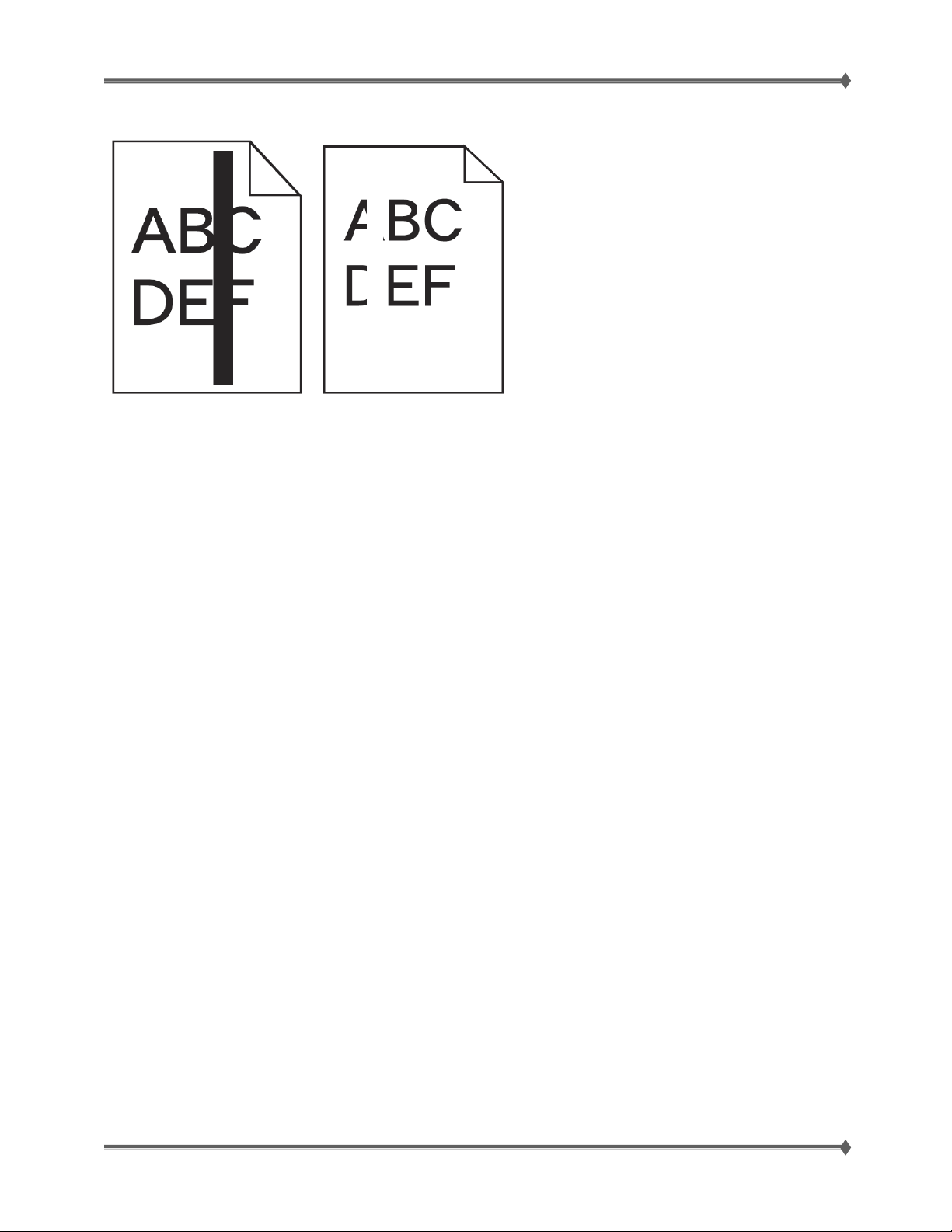
MAKE SURE THE FILL PATTERN IS CORRECT
If the fill pattern is incorrect, then choose a different fill pattern from your software program or application.
CHECK THE PAPER TYPE
• Try a different type of paper.
• Use only transparencies recommended by the printer manufacturer.
• Make sure the Paper Type and Paper Texture settings match the paper loaded in the tray or feeder.
CHECK THE TONER LEVEL. THE TONER MAY BE LOW.
• TIP: A toner cartridge that has been used in the machine long enough to be nearing the end of
life, may be gently shaken from side to side in order to level out any unevenness in the toner
reservoir that may have developed because of certain usage patterns or applications. As an
interim measure, this may allow the cartridge to be used a little longer.
THE PRINT CARTRIDGE MAY BE DEFECTIVE OR TOO LOW ON TONER
Replace the used print cartridge with a new one.
For Training Purposes Only 6/3/2009
34
Page 43
Lexmark T65x and X65x Mono Product Study Guide Rev 1.47
y
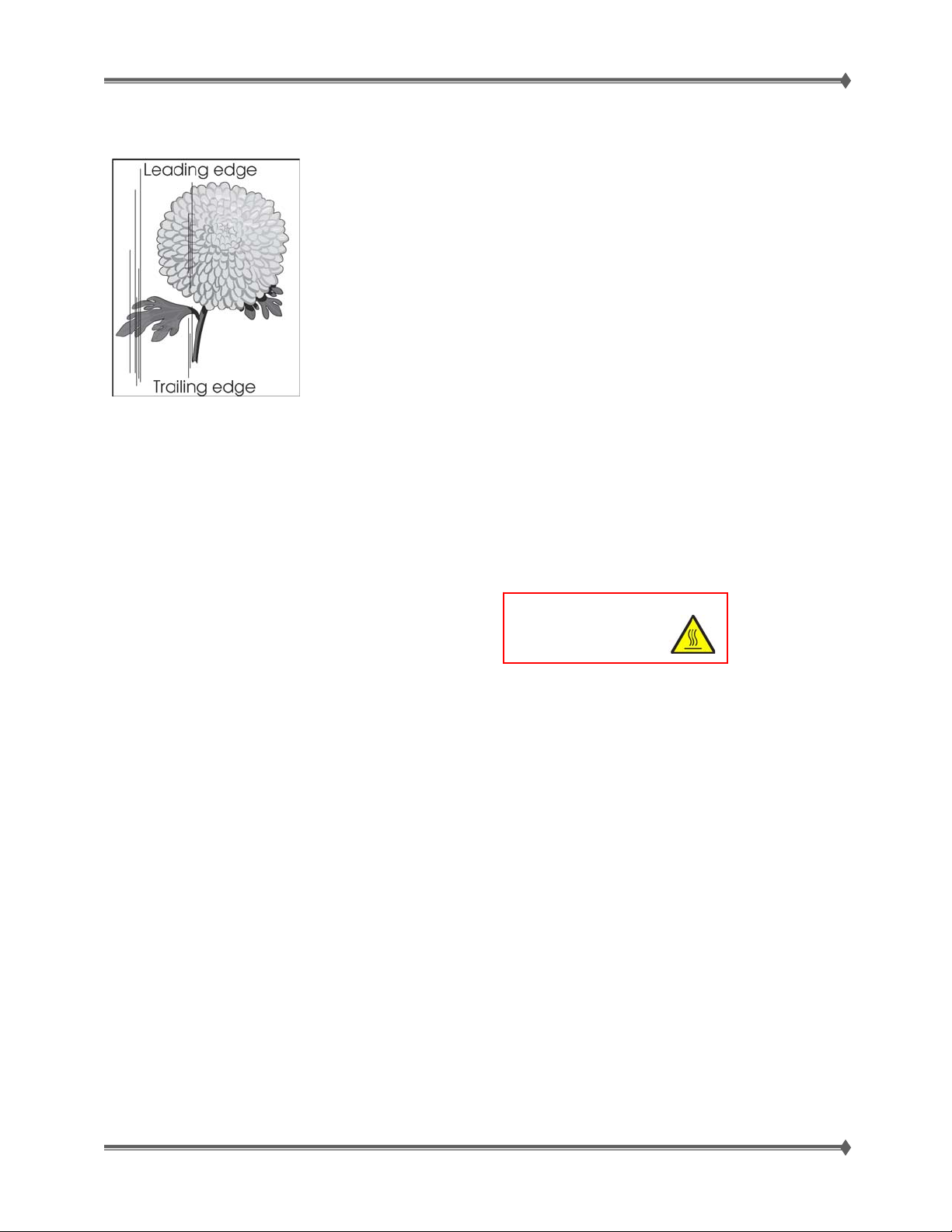
Vertical Stripes (process direction)
CHECK THE MEDIA CONDITION
Load new, dry, recommended media and re-print the defective image.
CHECK THE MEDIA TRANSFER ROUTE (PAPER PATH)
Make certain it is free of debris or contamination.
CHECK THAT THE TRANSFER ROLL ASSEMBLY IS FREE OF EXCESS WEAR & CONTAMINATION.
CHECK THE PRINT CARTRIDGE FOR SPOTS OR OTHER DAMAGE ON THE DRUM SURFACE.
Make certain that it is free of excess wear or contamination.
CHECK THE HEAT ROLL AND PRESSURE ROLL
Remove the fuser unit assembly.
Is there contamination or cracks on the heat roll and/or
pressure roll? If so, replace the fuser unit assembly.
CAUTION: : Allow the fuser unit
assembl
to cool down.
IF PROBLEM STILL PERSISTS; REPLACE THE SYSTEM CARD
For Training Purposes Only 6/3/2009
35
Page 44
Lexmark T65x and X65x Mono Product Study Guide Rev 1.47
y
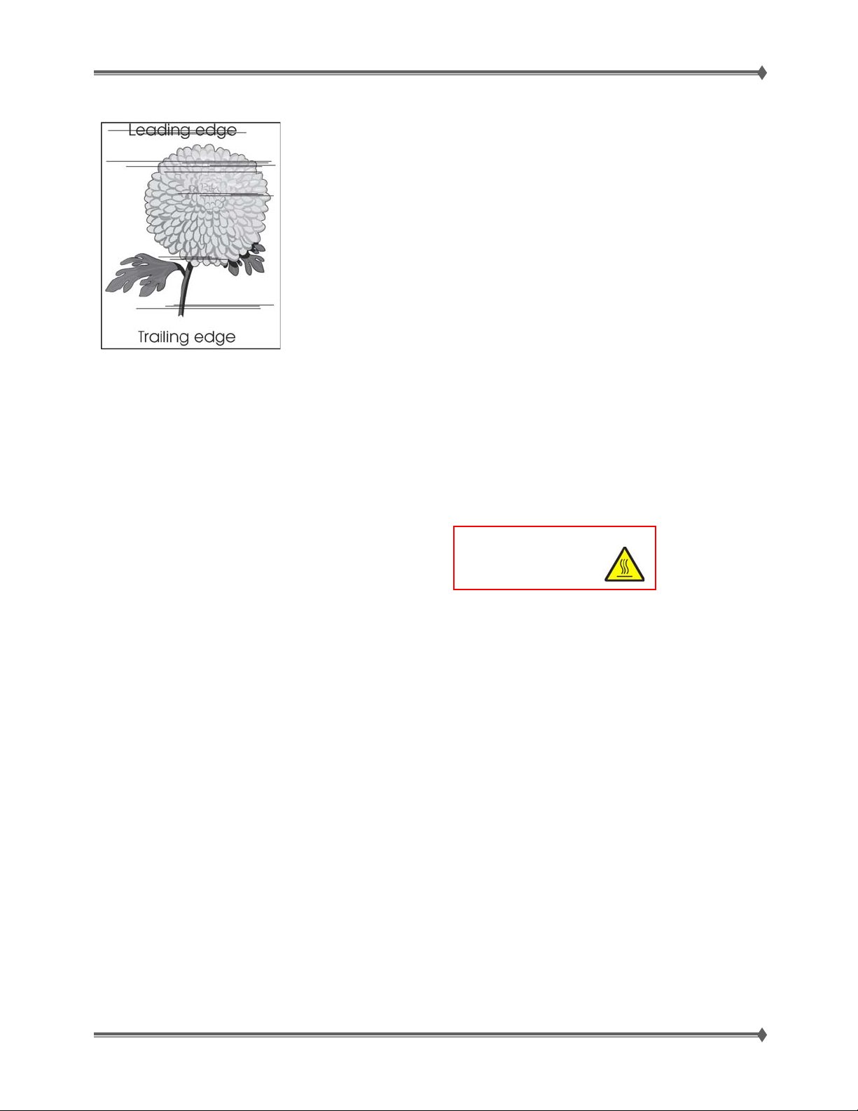
Horizontal stripes (side to side direction)
CHECK THE MEDIA CONDITION
Load new, dry, recommended media and re-print the defective image.
CHECK THE MEDIA TRANSFER ROUTE (PAPER PATH)
Make certain it is free of debris or contamination.
CHECK THE PRINT CARTRIDGE FOR SPOTS OR OTHER DAMAGE ON THE DRUM SURFACE.
Make Certain that it is free of excess wear or contamination.
CHECK THAT THE TRANSFER ROLL ASSEMBLY IS FREE OF EXCESS WEAR & CONTAMINATION.
CHECK THE HEAT ROLL AND PRESSURE ROLL
Remove the fuser unit assembly.
Is there contamination or cracks on the heat roll and/or
pressure roll? If so, replace the fuser unit assembly.
CAUTION: : Allow the fuser unit
assembl
to cool down.
CHECK THE HVPS CARD ASSEMBLY FOR PROPER CONNECTIONS
Reseat the connections properly.
If the component seems to be connected correctly, replace the HVPS card.
IF PROBLEM STILL PERSISTS; REPLACE THE SYSTEM CARD
For Training Purposes Only 6/3/2009
36
Page 45

Lexmark T65x and X65x Mono Product Study Guide Rev 1.47
Vertical void lines and bands (process direction)
CHECK THE MEDIA CONDITION
Load new, dry, recommended media and re-print the defective image.
CHECK THE MEDIA TRANSFER ROUTE (PAPER PATH)
Make certain it is free of debris or contamination.
CHECK THE LASER BEAM
Check the laser beam route.
Check for debris between the printhead assembly and the PC drum.
Check the four printhead assembly windows for contamination.
Is the laser beam route free of debris and the glass window, in the printhead assembly, free of
contamination?
CHECK THE TONER CARTRIDGE TO BE CERTAIN THAT IT IS INSTALLED CORRECTLY.
Inspect, clean and reinstall or replace print cartridge.
CHECK THAT THE TRANSFER ROLL ASSEMBLY IS FREE OF EXCESS WEAR & CONTAMINATION.
CHECK THE PRINTHEAD ASSEMBLY FOR PROPER CONNECTIONS
Reseat the connections properly.
If the component seems to be connected correctly, replace the printhead assemb ly.
CHECK THE SYSTEM CARD FOR PROPER CONNECTIONS
Reseat the connections properly.
If the component seems to be connected correctly, replace the system card.
For Training Purposes Only 6/3/2009
37
Page 46

Lexmark T65x and X65x Mono Product Study Guide Rev 1.47
Horizontal white stripes or bands (side to side direction)
CHECK THE MEDIA CONDITION
Load new, dry, recommended media and re-print the defective image.
CHECK THE MEDIA TRANSFER ROUTE (PAPER PATH)
Make certain it is free of debris or contamination.
CHECK THE TONER LEVEL. THE TONER MAY BE LOW.
• TIP: A toner cartridge that has been used in the machine long enough to be nearing the end of
life, may be gently shaken from side to side in order to level out any unevenness in the toner
reservoir that may have developed because of certain usage patterns or applications. As an
interim measure, this may allow the cartridge to be used a little longer.
CHECK THAT THE TRANSFER ROLL ASSEMBLY IS FREE OF EXCESS WEAR & CONTAMINATION.
CHECK THE PRINTHEAD ASSEMBLY FOR PROPER CONNECTIONS
Reseat the connections properly.
If the component seems to be connected correctly, replace the printhead assemb ly.
CHECK THE SYSTEM CARD FOR PROPER CONNECTIONS
Reseat the connections properly.
If the component seems to be connected correctly, replace the system card.
For Training Purposes Only 6/3/2009
38
Page 47
Lexmark T65x and X65x Mono Product Study Guide Rev 1.47
y
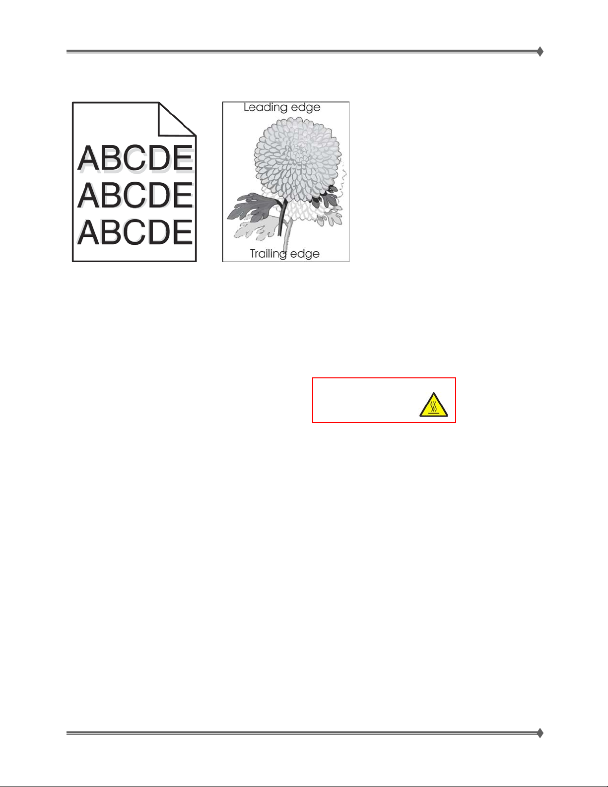
Ghost images (sometimes called after image)
The ghost appears on the
media which may be the
image from the previous
page or part of the page
currently printing.
CHECK THE PAPER TYPE SETTING
Make sure the paper type setting matches the paper loaded in the tray:
1. From the printer control panel, check the Paper Type setting from the Paper menu.
2. Before sending the job to print, specify the correct type setting:
- For Windows users, specify the type from Print Properties.
- For Macintosh users, specify the type from the Print dialog.
CHECK THE MEDIA CONDITION
Load new, dry, recommended media and re-print the defective image.
CHECK THE HEAT ROLL AND PRESSURE ROLL
Remove the fuser unit assembly.
Is there contamination or cracks on the heat roll and/or
pressure roll? If so, replace the fuser unit assembly.
CAUTION: : Allow the fuser unit
assembl
to cool down.
IF PROBLEM STILL PERSISTS; REPLACE THE SYSTEM CARD
For Training Purposes Only 6/3/2009
39
Page 48
Lexmark T65x and X65x Mono Product Study Guide Rev 1.47
y
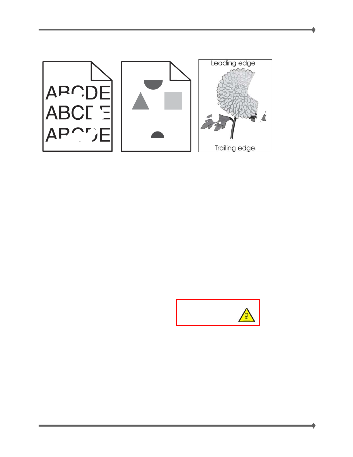
Print irregularities, Voids, Partial Lack
These are possible solutions. Try one or more of the following:
CHECK MEDIA CONDITION; PAPER MAY HAVE ABSORBED MOISTURE DUE TO HIGH HUMIDITY
• Load paper from a fresh
new, dry, recommended media package.
• TIP: Store paper in its original wrapper until you use it.
CHECK THE PAPER TYPE SETTING
Make sure the paper type setting matches the paper loaded in the tray:
1. From the printer control panel, check the Paper Type setting from the Paper menu.
2. Before sending the job to print, specify the correct type setting:
- For Windows users, specify the type from Print Properties.
- For Macintosh users, specify the type from the Print dialog.
CHECK THE PAPER; Avoid textured paper with rough finishes.
THE TONER MAY BE LOW
When 88 Cartridge low appears or when the print becomes faded, replace the print cartridge.
• TIP: A toner cartridge that has been used in the machine long enough to be nearing the end of
life, may be gently shaken from side to side in order to level out any unevenness in the toner
reservoir that may have developed because of certain usage patterns or applications. As an
interim measure, this may allow the cartridge to be used a little longer.
CHECK THE HEAT ROLL AND PRESSURE ROLL
Remove the fuser unit assembly.
CAUTION: : Allow the fuser unit
Is there contamination or cracks on the heat roll and/or
pressure roll? If so, replace the fuser unit assembly.
assembl
to cool down.
CHECK THE LASER BEAM
Check the laser beam route.
Check for debris between the printhead assembly and the PC drum.
Check the four printhead assembly windows for contamination.
Is the laser beam route free of debris and the glass window, in the printhead assembly, free of
contamination?
CHECK THAT THE TRANSFER ROLL ASSEMBLY IS FREE OF EXCESS WEAR & CONTAMINATION.
CHECK THAT THE PRINTHEAD IS PROPERLY INSTALLED.
IF PROBLEM STILL PERSISTS; REPLACE THE SYSTEM CARD
For Training Purposes Only 6/3/2009
40
Page 49

Lexmark T65x and X65x Mono Product Study Guide Rev 1.47
Faint print (Low contrast)
Before starting, check the media route (paper
path) for foreign objects, such as staples, clips,
paper scraps, etc in the media path.
CHECK MEDIA CONDITION; PAPER MAY HAVE ABSORBED MOISTURE DUE TO HIGH HUMIDITY
• Load paper from a fresh
• Check the Image density, make certain it is normal
• TIP: Store paper in its original wrapper until you use it.
CHECK THE TONER LEVEL. THE TONER MAY BE LOW. [REPLACE IF OUT OF TONER]
• TIP: A toner cartridge that has been used in the machine long enough to be nearing the end of
life, may be gently shaken from side to side in order to level out any unevenness in the toner
reservoir that may have developed because of certain usage patterns or applications. As an
interim measure, this may allow the cartridge to be used a little longer.
CHECK THE TRANSFER ROLL ASSEMBLY FOR EXCESS WEAR & CONTAMINATION.
CHECK THE TONER CARTRIDGE TO BE CERTAIN THAT IT IS INSTALLED CORRECTLY.
CHECK THE LASER BEAM
Check the laser beam route.
Check for debris between the printhead assembly and the PC drum.
Check the four printhead assembly windows for contamination.
Is the laser beam route free of debris and the glass window, in the printhead assembly, free of
contamination?
CHECK THE HVPS CARD ASSEMBLY FOR PROPER CONNECTIONS
Reseat the connections properly.
If the component seems to be connected correctly, replace the HVPS card.
CHECK THE PRINTHEAD ASSEMBLY FOR PROPER CONNECTIONS
Reseat the connections properly.
If the component seems to be connected correctly, replace the printhead assemb ly.
CHECK THE SYSTEM CARD FOR PROPER CONNECTIONS
Reseat the connections properly.
If the component seems to be connected correctly, replace the system card.
new, dry, recommended media package.
For Training Purposes Only 6/3/2009
41
Page 50

Lexmark T65x and X65x Mono Product Study Guide Rev 1.47
Background (fog)
CHECK THE MEDIA CONDITION
Load new, dry, recommended media and re-print the defective image.
CHECK THE MEDIA TRANSFER ROUTE (PAPER PATH)
Make certain it is free of debris or contamination.
CHECK THE TONER CARTRIDGE TO BE CERTAIN THAT IT IS INSTALLED CORRECTLY.
Inspect, clean and reinstall or replace print cartridge.
CHECK THE TRANSFER ROLL ASSEMBLY FOR EXCESS WEAR & CONTAMINATION.
CHECK THE HVPS CARD ASSEMBLY FOR PROPER CONNECTIONS
Reseat the connections properly.
If the component seems to be connected correctly, replace the HVPS card.
CHECK THE PRINTHEAD FOR PROPER INSTALLATION
Reseat the connections properly.
If the component seems to be installed and adjusted correctly, replace the printhead assembly.
IF PROBLEM STILL PERSISTS; REPLACE THE SYSTEM CARD
For Training Purposes Only 6/3/2009
42
Page 51
Lexmark T65x and X65x Mono Product Study Guide Rev 1.47
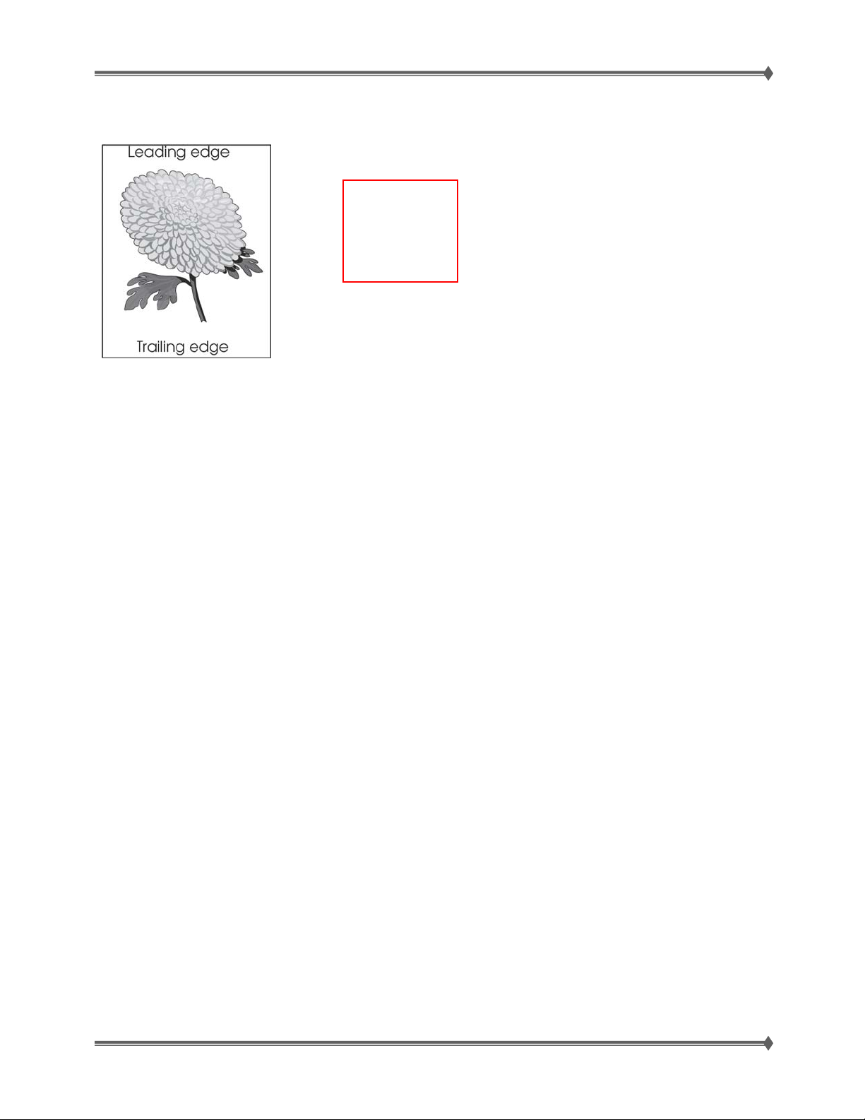
Skew
The printed
image is not
paralleled with
both sides of
the media
CHECK PRINTER INSTALLATION PLACEMENT
Check for installation surface irregularities. Check for a damaged printer caster. Correct as needed.
PROPERLY LOAD MEDIA INTO THE TRAY ASSEMBLY AND ENSURE ALL GUIDES ARE SET
CORRECTLY.
CHECK FOR OBSTRUCTIONS IN THE AREA OF THE MEDIA FEED UNITS.
CHECK THE TRANSFER ROLL ASSEMBLY FOR EXCESS WEAR & CONTAMINATION.
CHECK THE ALIGNER ASSEMBLY FOR PROPER ADJUSTMENTS
IF PROBLEM STILL PERSISTS; REPLACE THE SYSTEM CARD
For Training Purposes Only 6/3/2009
43
Page 52
Lexmark T65x and X65x Mono Product Study Guide Rev 1.47
y
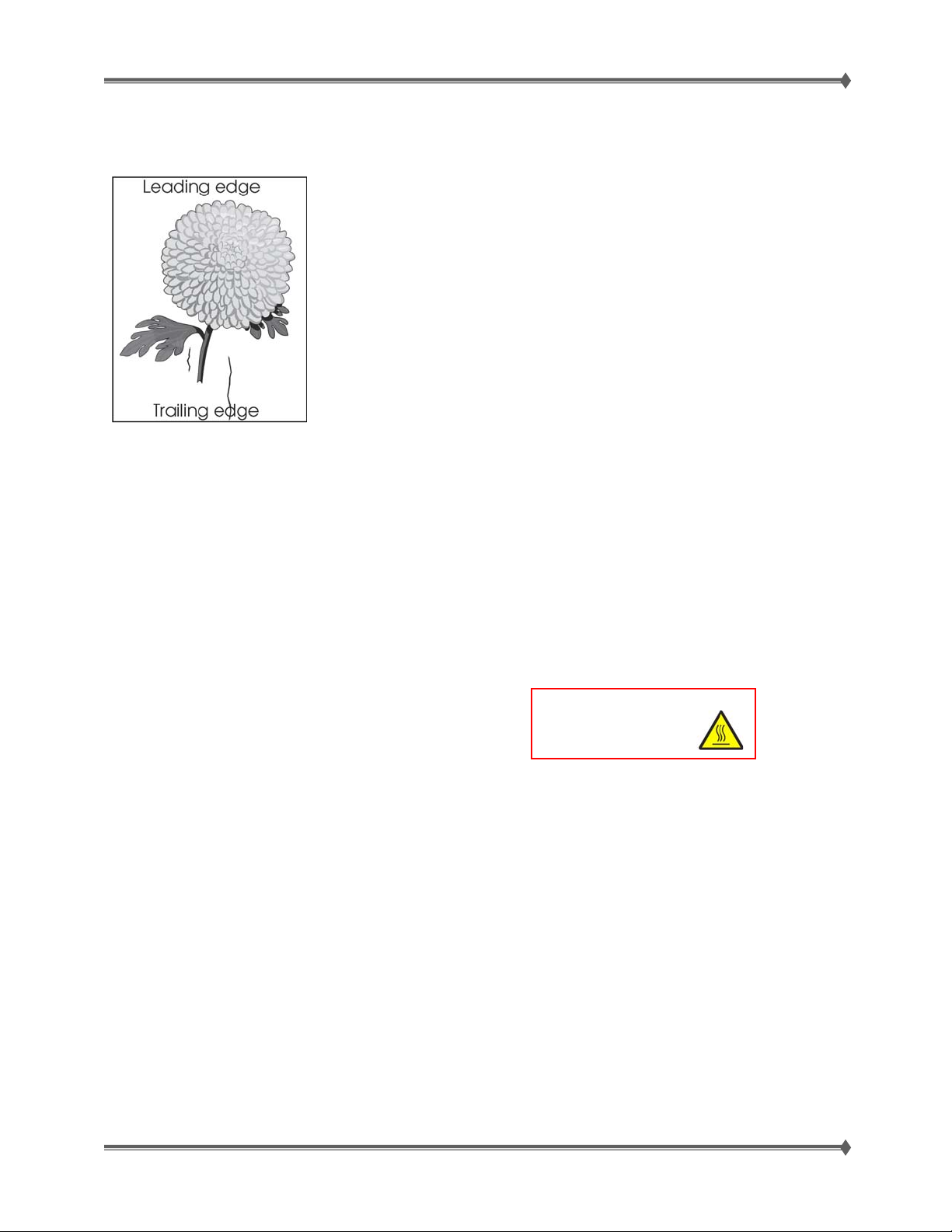
Media Damage
CHECK PRINTER INSTALLATION PLACEMENT
Check for installation surface irregularities. Check for a damaged printer caster. Correct as needed.
CHECK THE MEDIA FEED
Remove the media tray assembly
Properly load media in the tray assembly
Properly install media tray assembly in the printer.
CHECK THE MEDIA CONDITION
Load new, dry, recommended media and re-print the defective image.
CHECK THE TRANSFER ROLL ASSEMBLY FOR EXCESS WEAR & CONTAMINATION.
CHECK THE ALIGNER ASSEMBLY FOR PROPER ADJUSTMENTS
CHECK THE HEAT ROLL AND PRESSURE ROLL
CAUTION: : Allow the fuser unit
Remove the fuser unit assembly.
Is there contamination or cracks on the heat roll and/or
pressure roll? If so, replace the fuser unit assembly.
assembl
to cool down.
For Training Purposes Only 6/3/2009
44
Page 53
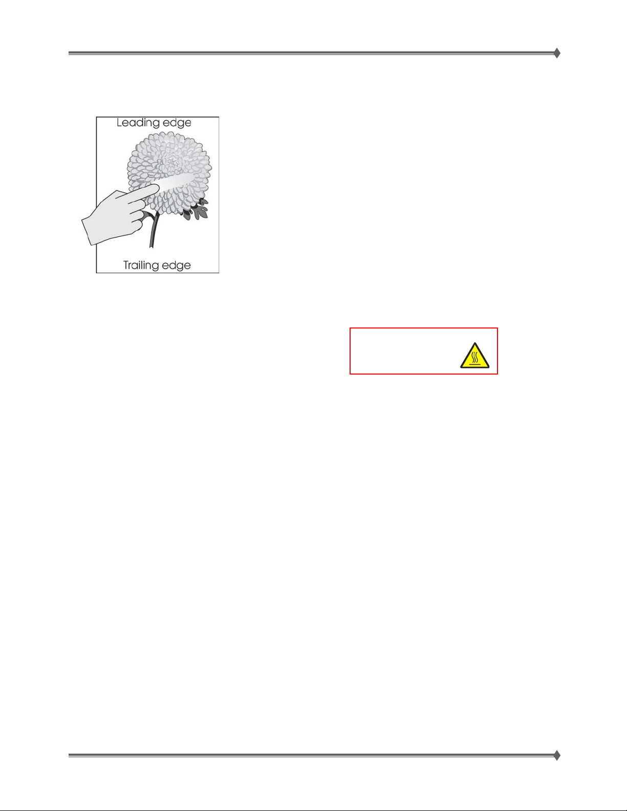
Lexmark T65x and X65x Mono Product Study Guide Rev 1.47
y
No fuse (unfused toner, smearing)
CHECK THE FUSER UNIT ASSEMBLY INSTALLATION, REINSTALL AS NEEDED.
CHECK THE MEDIA CONDITION
Load new, dry, recommended media and re-print the defective image.
CHECK THE HEAT ROLL AND PRESSURE ROLL
CAUTION: : Allow the fuser unit
Remove the fuser unit assembly.
Is there contamination or cracks on the heat roll and/or
assembl
to cool down.
pressure roll? If so, replace the fuser unit assembly.
CHECK THE LVPS CARD ASSEMBLY FOR PROPER CONNECTIONS
Reseat the connections properly.
If the component seems to be connected correctly, replace the LVPS card.
IF PROBLEM STILL PERSISTS; REPLACE THE SYSTEM CARD
For Training Purposes Only 6/3/2009
45
Page 54

Lexmark T65x and X65x Mono Product Study Guide Rev 1.47
Paper Transport Diagnostics
Paper Rules of Thumb
Paper jams and feed problems occur for numerous reasons. Sometimes, failure of the equipment is the
cause or it can be the result of other external factors. Before replacing parts for a feed problem, ask
these questions:
• Is the customer using a supported media type? This is a common problem. Check the
printer specifications if you are not sure.
• Is the customer using a supported media size? Check the printer specifications of you are
not sure.
• Is the customer using a supported media weight? This is a common problem. Check the
printer specifications of you are not sure.
• Have you tried printing with a fresh ream of paper? Paper that is left out of the package for
periods of time can dry out or absorb moisture.
• Have you tried printing from a different input source? This will help narrow down the cause of
some problems.
• Is too much paper loaded in the Tray? Make sure the stack height does not exceed the
indicated maximum height.
• Is the paper in the Tray wrinkled, creased, damp, or curled? Paper will not feed properly if it
is damaged. Try a fresh ream of paper.
• Are different media types and/or weights loaded in the Tray? This will cause misfeeds.
• Is the relative humidity too high? Too low? This can affect the media and/or printer and its
ability to feed properly. Check the printer specifications to see if it is located in an ambient
environment.
• Is the paper loaded properly in the Tray or option? This is a common problem. Reposition
the paper in the Tray or option to make sure that is loaded properly. The paper guides
should be flush against the media, but not too tight.
• Are the feed rollers worn because it is time for a maintenance kit? Check the page count of
the printer to see if it is time for a maintenance kit to be installed.
• Are there any obstructions in the paper path? If paper, staples, paper clips or other items are
left in the printer, they can prevent the media from feeding properly.
Save yourself time and effort and always check these external influences before spending time
troubleshooting a supposed equipment failure.
For Training Purposes Only 6/3/2009
46
Page 55
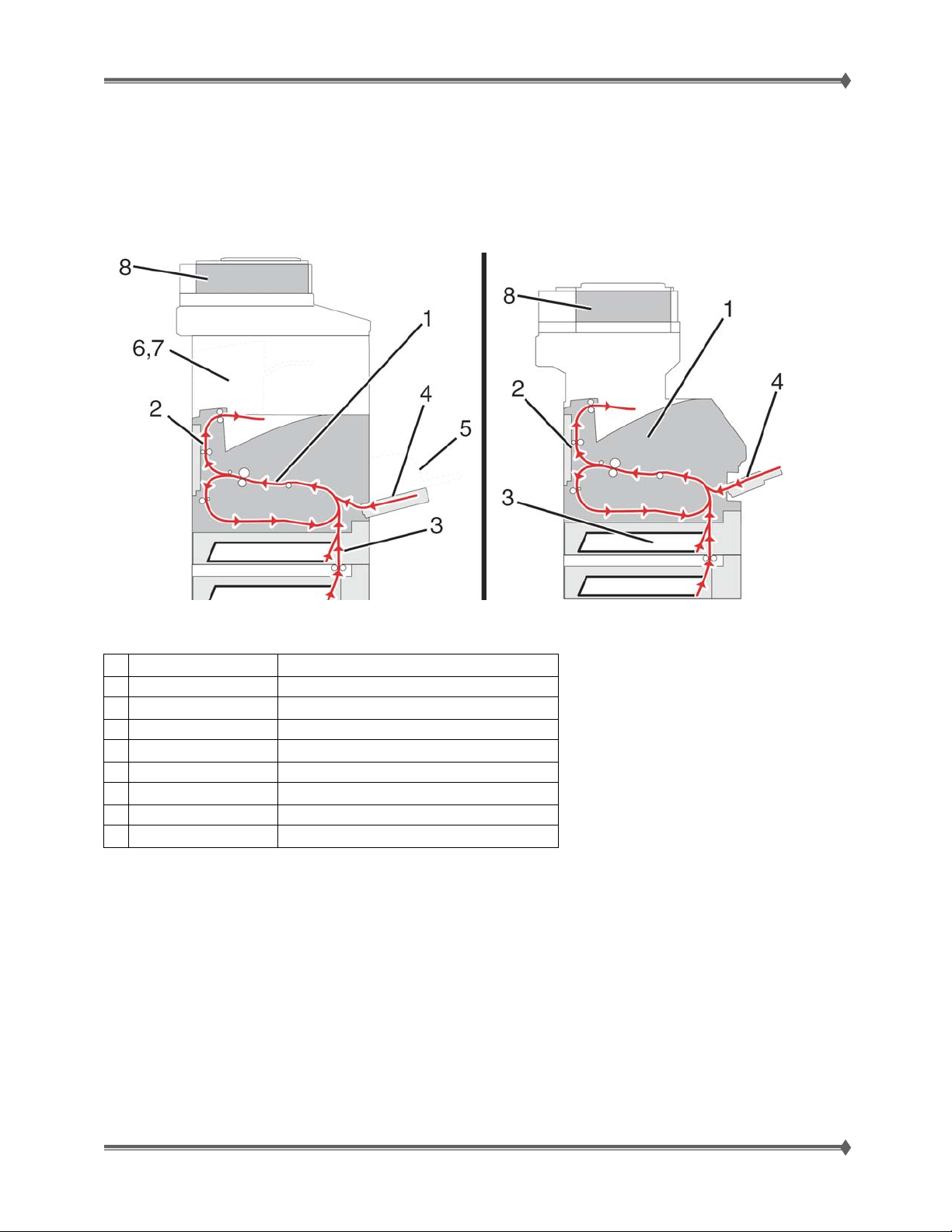
Lexmark T65x and X65x Mono Product Study Guide Rev 1.47
Understanding jam numbers and locations
When a jam occurs, a message indicating the jam location appears. Open doors and covers and remove
trays to access jam locations. To resolve any paper jam message, you must clear all jammed paper from
the paper path. The scanner portion [8] of the diagrams below applies to the X65x units only.
The following table lists the jams that can occur and the general location of each jam:
Jam numbers Area
1 200—203 Printer
2 230—239 Duplex unit
3 241—245 Paper tray
4 250 Multipurpose feeder
5 260 Envelope feeder
6 270—279 Optional Output bin
7 280—283 Stapler
8 290—294 ADF
For Training Purposes Only 6/3/2009
47
Page 56
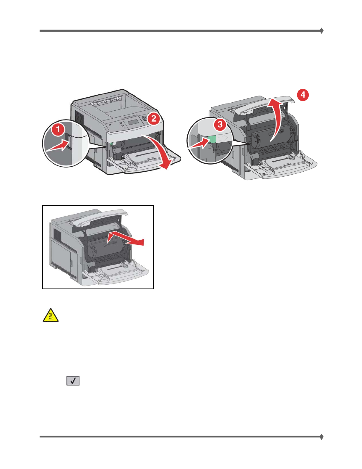
Lexmark T65x and X65x Mono Product Study Guide Rev 1.47
200 and 201 paper jams
1. Push the release latch, and then lower the multipurpose feeder door.
2. Push the release latch, and then open the front cover.
3. Lift and pull the print cartridge out of the printer.
WARNING: Do not touch the photoconductor drum on the underside of the cartridge. Use the cartridge
handle whenever you are holding the cartridge.
4. Place the print cartridge aside on a
flat, smooth surface.
WARNING: Do not leave the cartridge
exposed to light for extended periods.
WARNING: The jammed paper may be
covered with unfused toner which can
stain garments and skin.
. Remove the jammed paper.
5
CAUTION: The inside of the printer might be hot. To reduce the risk of injury from a hot
component, allow the surface to cool before touching.
Note: If the paper is not easy to remove, then open the rear door and remove the paper from there.
6. Align and reinstall the print cartridge.
7. Close the front cover.
8. Close the multipurpose feeder door.
9. Press .
For Training Purposes Only 6/3/2009
48
Page 57
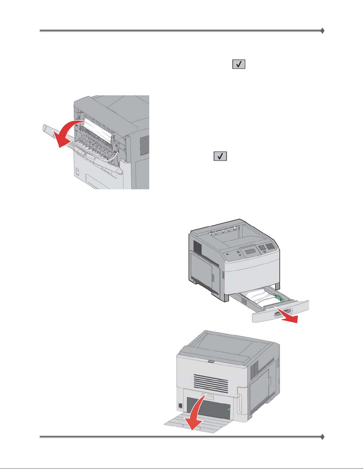
Lexmark T65x and X65x Mono Product Study Guide Rev 1.47
202 and 203 paper jams
If the paper is exiting the printer, then pull the paper out, and then press .
If the paper is not exiting the printer:
1. Pull down the top rear door.
2. Slowly remove the jammed paper to
avoid tearing it.
3. Close the top rear door.
4. Press .
230 Paper Jam
Rear Paper Jams
1. Remove the standard tray from the printer.
2. Pull down the bottom rear door
For Training Purposes Only 6/3/2009
49
Page 58
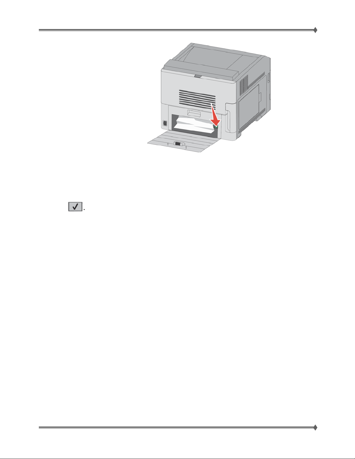
Lexmark T65x and X65x Mono Product Study Guide Rev 1.47
3. Push the tab down.
4. Remove the jammed paper.
5. Close the bottom rear door.
6. Insert the standard tray.
7. Press
For Training Purposes Only 6/3/2009
50
Page 59
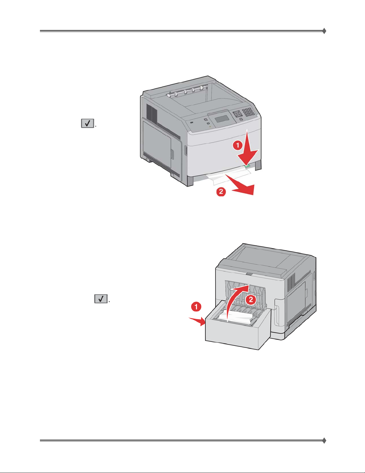
Lexmark T65x and X65x Mono Product Study Guide Rev 1.47
Front Paper jams
1. Remove the standard tray from the printer.
2. Push the tab down.
3. Remove the jammed paper.
4. Insert the standard tray.
5. Press
231-239 paper jams (optional external duplex unit)
Rear Paper jams
1. Push in and hold the latch while
pulling up the rear duplex door.
2. Remove the jammed paper.
3. Close the rear duplex door.
4. Press
For Training Purposes Only 6/3/2009
51
Page 60
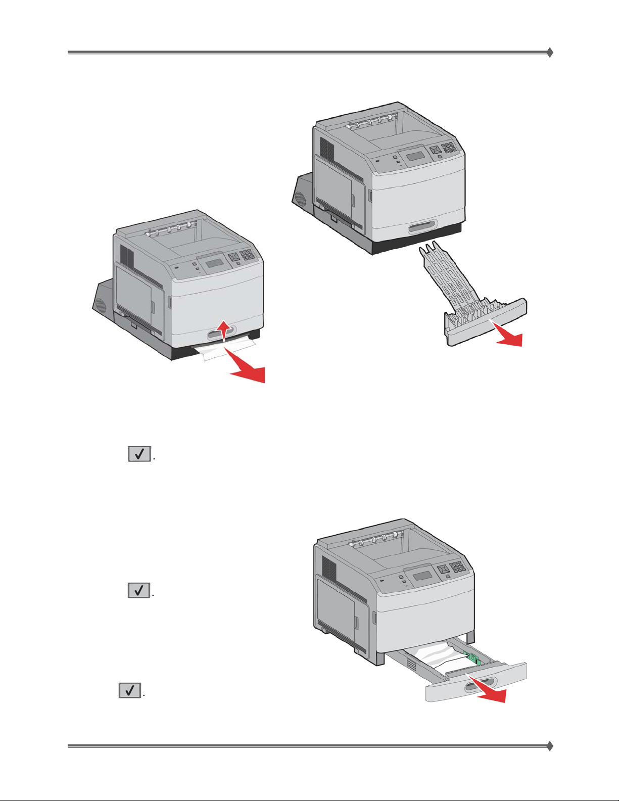
Lexmark T65x and X65x Mono Product Study Guide Rev 1.47
Front Paper Jam
1. Remove the standard tray from the printer.
2. Remove the duplex jam access tray.
3. Raise the recessed duplex bar.
4. Remove the jammed paper,.
5. Replace the duplex jam access tray.
6. Insert the standard tray.
7. Press
241-245 paper jams
1. Pull out the tray indicated on the display.
2. Remove any jammed paper, and then insert
the tray.
3. Press
4. If the jam message remains for a 250-sheet
or 550-sheet tray, then remove the tray from the
printer.
5. Remove the jammed paper, and then insert
the tray.
6. Press
For Training Purposes Only 6/3/2009
52
Page 61
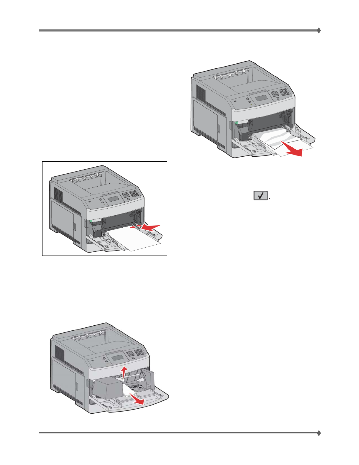
Lexmark T65x and X65x Mono Product Study Guide Rev 1.47
250 paper jam
1. Remove the paper from the multipurpose feeder.
2. Flex the sheets of paper back and forth to loosen
them, and then fan them. Do not fold or crease the
paper.
Straighten the edges on a level surface.
3. Load the paper into the multipurpose feeder.
4. Slide the paper guide toward the inside of the
tray until it lightly rests against the edge of the paper.
5. Press
260 paper jam
The envelope feeder feeds envelopes from the bottom of the stack; the bottom envelope will be the one
that is jammed.
1. Lift the envelope weight, and then remove all the envelopes.
4. Reinstall the envelope feeder. Make sure it snaps into place.
2. If the jammed envelope has entered the
printer and cannot be pulled out, then lift the
envelope feeder up and then out of the printer,
and then set it aside.
3. Remove the envelope from the printer.
Note: If you cannot remove the envelope, the
print cartridge will have to be removed.
[see instructions in 200-201 paper jams]
For Training Purposes Only 6/3/2009
53
Page 62
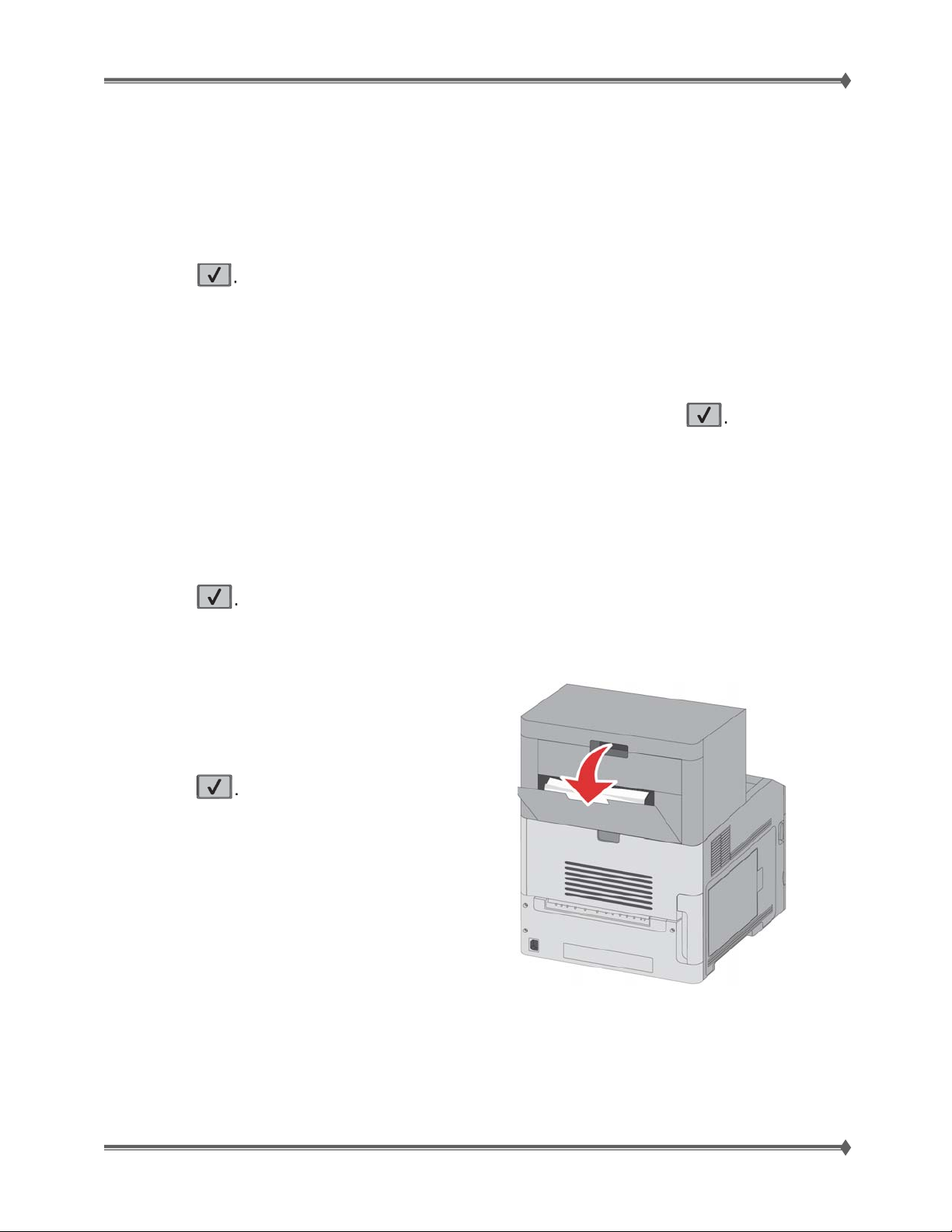
Lexmark T65x and X65x Mono Product Study Guide Rev 1.47
5. Flex and stack the envelopes.
6. Load the envelopes in the envelope feeder.
7. Adjust the paper guide.
8. Lower the envelope weight.
9. Press
271-279 paper jams
To clear a jam in the output expander, high-capacity output stacker, the 5-bin mailbox, or the StapleSmart
II Finisher:
1. If the paper is exiting into a bin, then pull the paper straight out, and then press If not, then
continue with step 2.
2. Pull down the output bin door or doors.
3. Remove the jammed paper.
4. Close the output bin door or doors.
5. Press
280 paper jam
1. Pull down the StapleSmart II Finisher door.
2. Remove the jammed paper.
3. Close the StapleSmart ii Finisher door.
4. Press
For Training Purposes Only 6/3/2009
54
Page 63
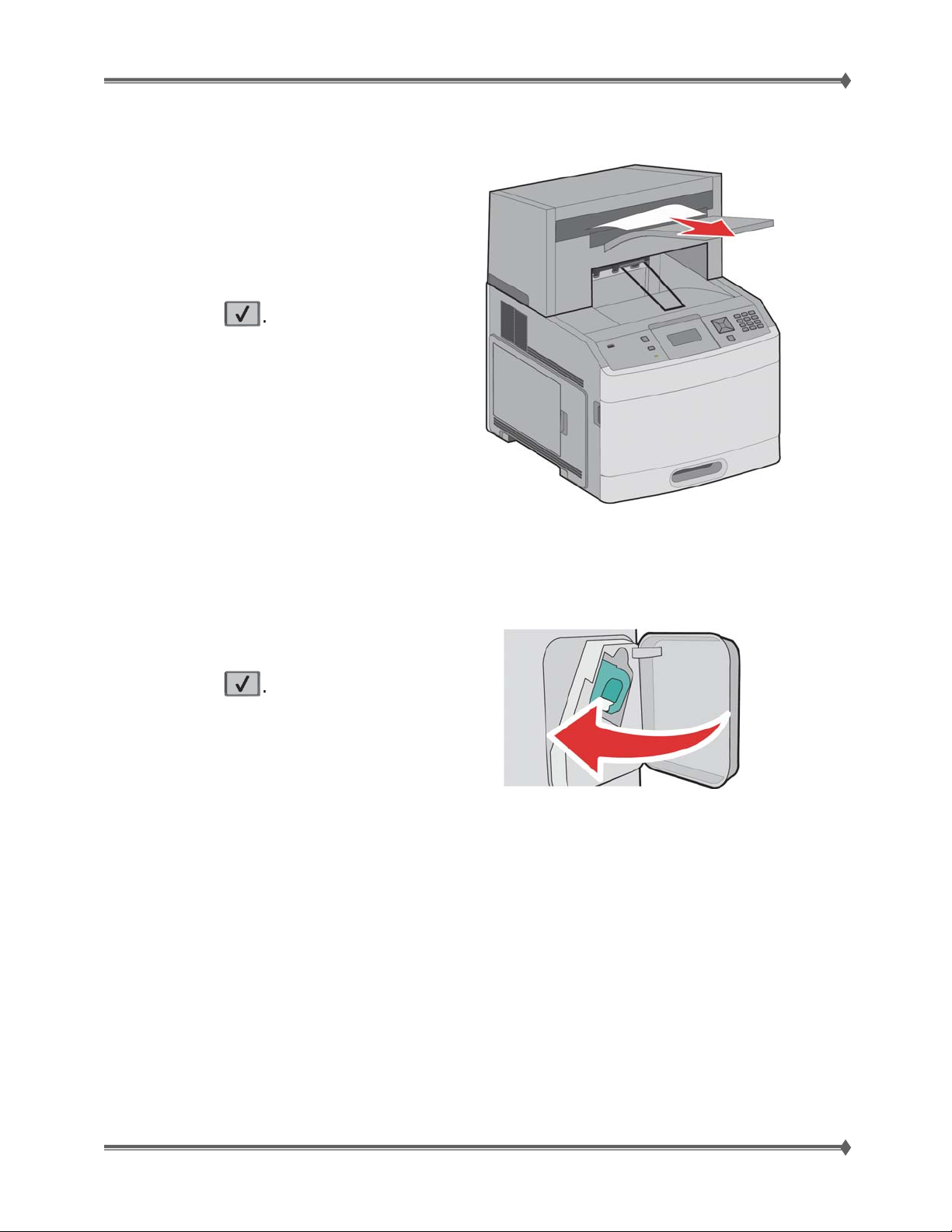
Lexmark T65x and X65x Mono Product Study Guide Rev 1.47
281 paper jam
1. Clear the jam from the stapler output bin.
2. Press
282 paper jam
To prevent paper jams, the stapler motor does not run when the stapler door is open.
1. Close the stapler door until it clicks into place.
2. Press
For Training Purposes Only 6/3/2009
55
Page 64
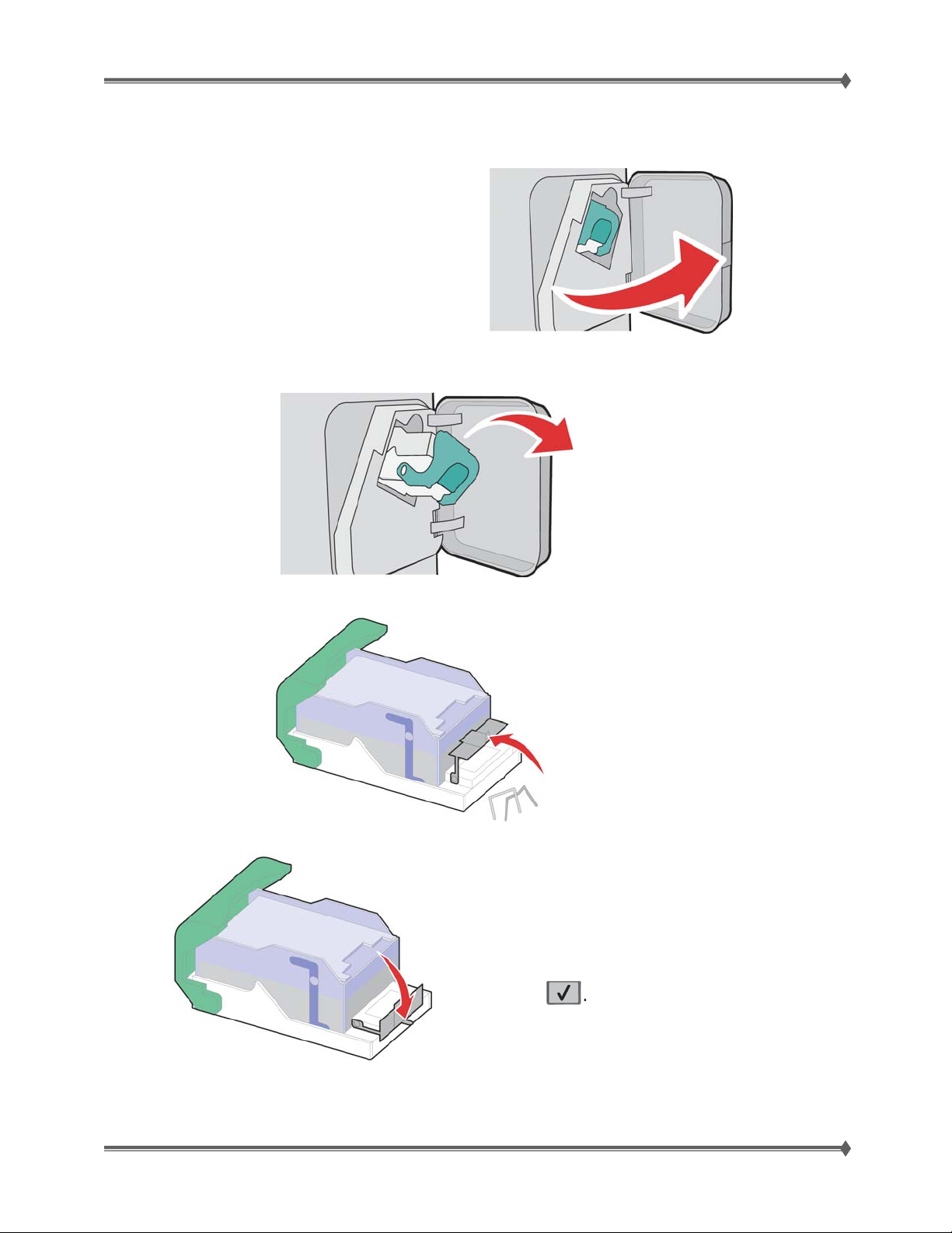
Lexmark T65x and X65x Mono Product Study Guide Rev 1.47
283 staple jam
1. Press the latch to open the stapler door.
2. Pull the latch of the staple cartridge holder down, and then pull the holder out of the printer.
3. Use the metal tab to lift the staple guard, and then remove any loose staples.
3. Press down on the staple guard until it snaps into place.
5. Push the cartridge holder firmly back into the
stapler unit until the cartridge holder clicks into
place.
6. Close the stapler door.
7. Press
For Training Purposes Only 6/3/2009
56
Page 65
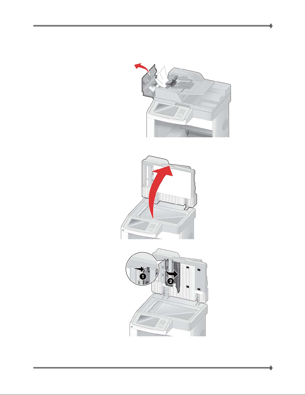
Lexmark T65x and X65x Mono Product Study Guide Rev 1.47
290-294 paper jams
1. Remove all original documents from the ADF.
2. Open the ADF cover, and then remove any jammed paper.
3. Close the ADF cover.
4. Open the scanner cover, and then remove any jammed pages.
5. Open the bottom ADF door, and then remove any jammed pages.
6. Close the bottom ADF door and scanner cover.
7. Touch Restart Job.
For Training Purposes Only 6/3/2009
57
Page 66

Lexmark T65x and X65x Mono Product Study Guide Rev 1.47
Potential Field Issues
The following are items that may generate questions or calls.
1) ADF edge guides should lightly touch media, as scanning.
Paper tray & ADF input recommendations
• Make sure the paper lies flat in the paper tray.
• Do not remove paper trays while the printer is printing.
• Do not load paper trays, the multipurpose feeder, or the envelope feeder while the printer is
printing. Load them prior to printing, or wait for a prompt to load them.
• Do not load too much paper. Make sure the stack height does not exceed the indicated
maximum height indicated in the tray or input devise.
• Make sure the guides in the paper trays, multipurpose feeder, ADF input devise or
envelope feeder are properly positioned and are not pressing too tightly against the paper
or envelopes.
• Push all trays in firmly after loading paper.
2) No mixed width medias in ADF
Paper recommendations
• Use only recommended paper or specialty media. For more information, see “Paper types and
weights supported by the printer” in the Users Guide
• Do not load wrinkled, creased, damp, bent, or curled paper.
• Flex, fan, and straighten paper before loading it.
• Do not use paper that has been cut or trimmed by hand.
• Do not mix paper sizes, weights, or types in the same stack.
• Make sure all sizes and types are set correctly in the printer control panel menus.
• Store paper per the manufacturer's recommendations.
3) Error codes associated with side guides being too tight or too loose:
• Too Loose
234.00
242.09
• Too Tight
24x.04
241.10
241.14
For Training Purposes Only 6/3/2009
58
Page 67
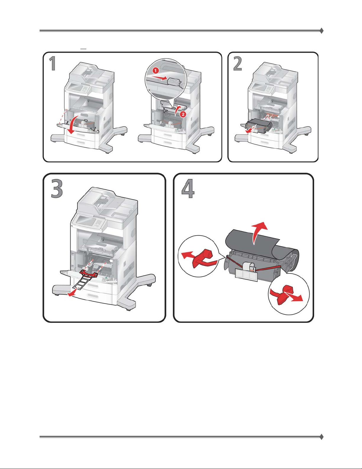
Lexmark T65x and X65x Mono Product Study Guide Rev 1.47
4) Make sure all packing material is removed, prior to powering on PC.
For Training Purposes Only 6/3/2009
59
Page 68
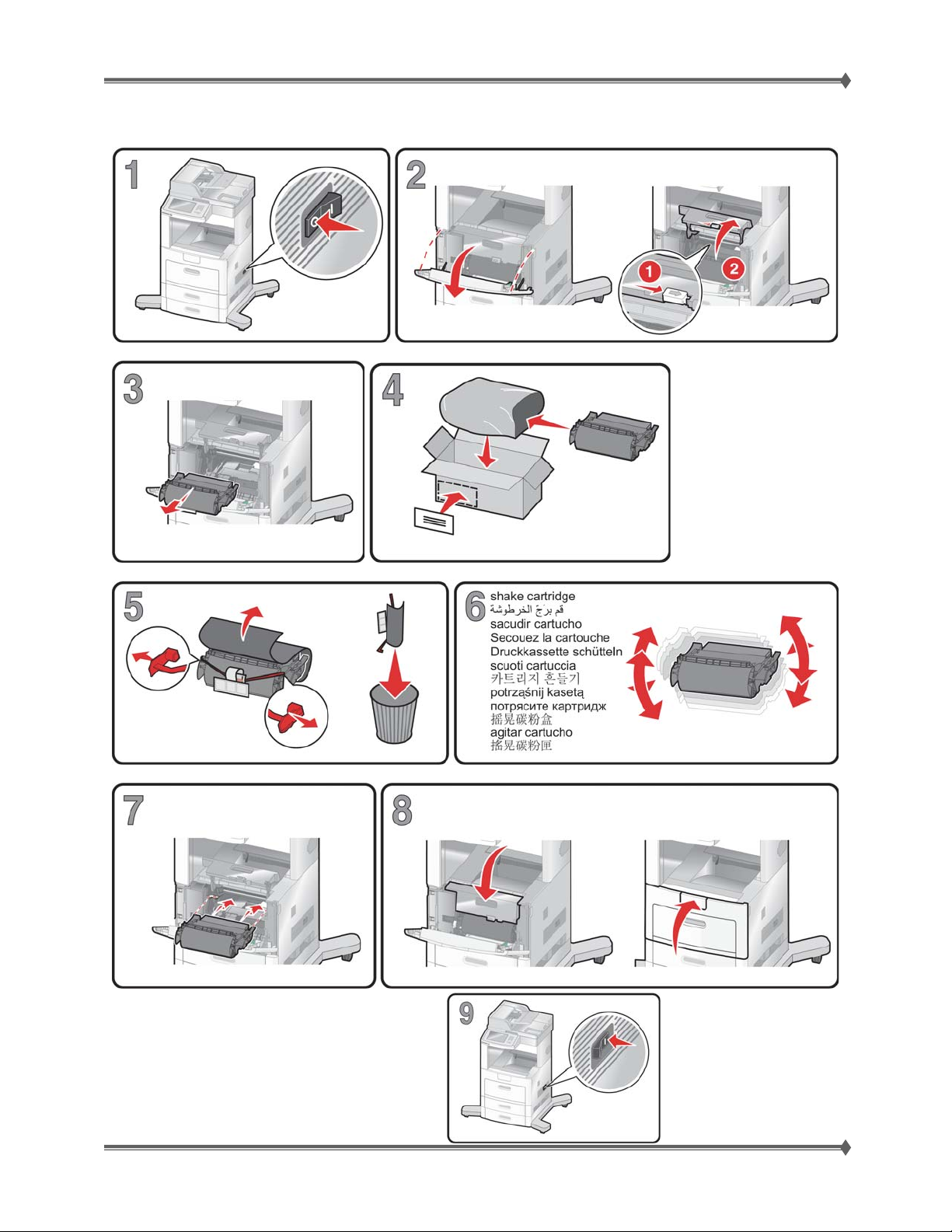
Lexmark T65x and X65x Mono Product Study Guide Rev 1.47
5) Be certain all media has been removed from the output tray & the front door is completely open, prior
to removing print cartridge. The correct steps are shown in the pictorial drawings below.
The last step is to turn the devise back on.
For Training Purposes Only 6/3/2009
60
Page 69
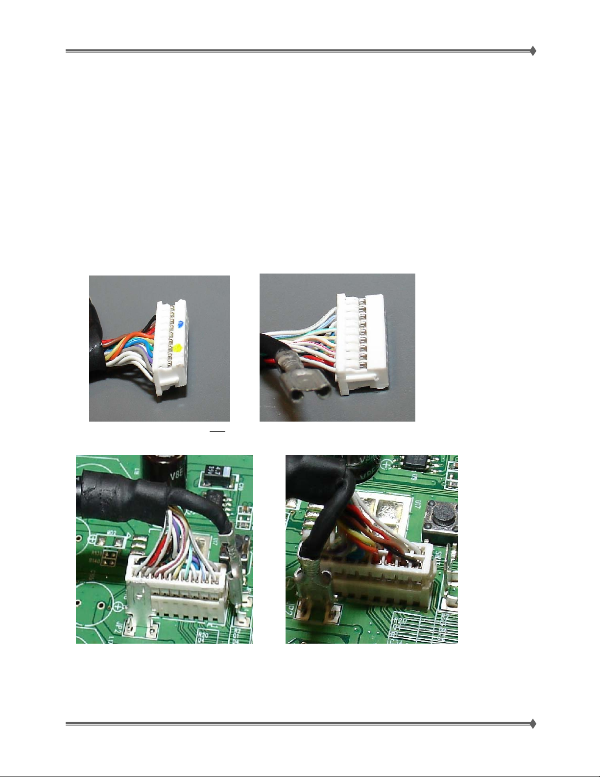
Lexmark T65x and X65x Mono Product Study Guide Rev 1.47
General Notes:
Mirrored MVRAM
• NOTE: The generic FRU will mirror and lock during a standard POR. In orde r to test a generic
FRU for diagnostic purposes, you must bring the machine up in the diagnostic mode.
• If a part was locked by a machine but it did not fix the problem, it cannot be used in another
machine. It needs to be sent back for re-certification.
Operator Panel Assembly Cable – X65x
• CAUTION: Please take note of the pictures below. The connector for the Operator Panel
Assembly for the X65x is keyed, and needs to be carefully installed to match up the keyed edges.
Please note that the plug can physically be reversed and forced to plug in incorrectly.
The cable is keyed and can
This is the correct way to install the cable. The picture above is installed incorrectly.
be plugged in backwards (reversed 180˚)
For Training Purposes Only 6/3/2009
61
Page 70

Lexmark T65x and X65x Mono Product Study Guide Rev 1.47
Lexmark T65x Print Driver– Core Skills Course
In order to provide you with the most current information, the general guidelines and latest information
pertaining to the drivers, and driver installation can be located in the Core Skills Course fund on Infrature.
Diagnostic Tools Available for Technicians
This section provides an overview and explanation of the various tools made available to technicians to
assist them in providing excellent customer support.
Service Manuals
Lexmark service manuals provide general information on the products, including diagnostics, repair,
removals and a parts catalogue which provides you all the FRU’s and graphi c representation of the
FRU’s.
Technical Service Bulletins
Technical Service Bulletins provide important and sometimes urgent service information and procedures
that are not included in Lexmark's current service documentation.
Technical Service Bulletins can be accessed by contacting your next level of support.
For Training Purposes Only 6/3/2009
62
 Loading...