

Page 1

Revised: December 20, 2006
Lexmark™ T62X
4069-5xx/7xx
• Table of Contents
•Start Diagnostics
• Safety and Notices
• Trademarks
•Index
Lexmark and Lexmark with diamond
design are trade ma rks of Lexmark
International, Inc., registered in the
United States and/or ot her countries.
Page 2

T
T
t
©
A
T
4069-5XX/7XX
Edition: December 20, 2006
he following paragraph does not apply to any country where such provisions are
inconsistent with local law: LEXMARK INTERN ATIONAL, INC. PROVIDES THIS
PUBLICATION “AS IS” WITHOUT WARRANTY OF ANY KIND , EITHER EXPRESS OR
IMPLIED, INCLUDING , BUT NOT LIMITED TO, THE IMPLIED W A RRANTIES OF
MERCHANT ABI LITY OR FITNESS FOR A PARTICULAR PURPOSE. Some states do not
allow disclai mer of e x press or implied w arranties in certain transactions; therefore, this
statement may not apply to you.
his publication could include technical inaccuracies or typographical errors. Changes are
periodically made to the informa tion her ein; these change s will be i ncorporated in late r
editions. Improv ements or changes in the products or the prog rams descr ibed may be
made at any time.
Comments may be addressed to Lexmark International, Inc., Departme nt D22A/03 2-2,
740 West New Circle Road, Lexington, Kentucky 40550, U.S.A or e-mail at
ServiceInfoAndTraining@Lexmark.com. Lexmark may use or distribute any of the
information you supply in any way it believes approp riate without incurring any obligation
o you.
Image Q uick, O ptra Forms, Pi ctureGr ade and St apleSmart are trademarks of Lexmark
International, Inc.
Lexmark and Lexmark with diamond design, Prebate an d Ma rk N e t are tr ad em arks of
Lexmark Intern ational, Inc., registered in the United States and /or othe r countries.
PostScript is a registered trademark of Adobe Systems Incorporated.
PCL is a register ed trad emark of the Hewlett-Packard Company.
Other trademarks are the property of their r espective own ers.
Copyright Lexma rk Inte r na tion al, Inc. 20 01.
ll rights reserved.
UNITED STATES GOVERNMENT RESTRICTED RIGHTS
his software and documentation are provided with RESTRICTED RIGHTS. Use,
duplic ation or disclosure by the Gov ernment is subject to restrict ions as set forth in
subparagraph (c)(1 )(ii) of the Rights in Technical Data and Com puter Software cl ause at
DFARS 252.227-7013 and in applicable F AR provisions: Lexmark International, Inc.,
Lexington, KY 40550.
P/N: 12G3959
Page 3

4069-5XX/7XX
Table of Content
Laser Notices . . . . . . . . . . . . . . . . . . . . . . . . . . . . . . . . . . . . . . . . . .1-ix
Safety Information. . . . . . . . . . . . . . . . . . . . . . . . . . . . . . . . . . . . .1-xix
Preface. . . . . . . . . . . . . . . . . . . . . . . . . . . . . . . . . . . . . . . . . . . . .1-xxiv
General Information . . . . . . . . . . . . . . . . . . . . . . . . . . . . . . . . . . . . 1-1
Options . . . . . . . . . . . . . . . . . . . . . . . . . . . . . . . . . . . . . . . . . . . 1-2
Maintenance Approach . . . . . . . . . . . . . . . . . . . . . . . . . . . . . . . 1-3
Tools Required for Service . . . . . . . . . . . . . . . . . . . . . . . . . . . . 1-3
Acronyms . . . . . . . . . . . . . . . . . . . . . . . . . . . . . . . . . . . . . . . . . 1-4
Diagnostic Information . . . . . . . . . . . . . . . . . . . . . . . . . . . . . . . . . 2-1
Start . . . . . . . . . . . . . . . . . . . . . . . . . . . . . . . . . . . . . . . . . . . . . 2-1
Service Error Codes. . . . . . . . . . . . . . . . . . . . . . . . . . . . . . 2-2
User Status Screens . . . . . . . . . . . . . . . . . . . . . . . . . . . . 2-24
User Attendance Messages. . . . . . . . . . . . . . . . . . . . . . . 2-29
Power-On Self Test (POST) . . . . . . . . . . . . . . . . . . . . . . 2-41
Symptom Tables . . . . . . . . . . . . . . . . . . . . . . . . . . . . . . . 2-42
Service Checks . . . . . . . . . . . . . . . . . . . . . . . . . . . . . . . . . . . . 2-46
Charge Roll Service Check . . . . . . . . . . . . . . . . . . . . . . . 2-47
Cover Open Switch/Cable Service Check . . . . . . . . . . . . 2-49
Dead Machine Service Check . . . . . . . . . . . . . . . . . . . . . 2-50
Duplex Option Service Check . . . . . . . . . . . . . . . . . . . . . 2-53
Envelope Feeder Option Service Check . . . . . . . . . . . . . 2-56
Fan Service Check. . . . . . . . . . . . . . . . . . . . . . . . . . . . . . 2-63
Cold Fuser Service Check. . . . . . . . . . . . . . . . . . . . . . . . 2-65
Hot Fuser Service Check . . . . . . . . . . . . . . . . . . . . . . . . . 2-67
Fuser Solenoid Service Check. . . . . . . . . . . . . . . . . . . . . 2-68
Input Sensor Service Check . . . . . . . . . . . . . . . . . . . . . . 2-68
Input Tray(s) Option Service Check . . . . . . . . . . . . . . . . . 2-69
High-Capacity Feeder Input Tray Service Check. . . . . . . 2-72
Main Drive Service Check . . . . . . . . . . . . . . . . . . . . . . . . 2-85
Operator Panel Service Check . . . . . . . . . . . . . . . . . . . . 2-86
Options Service Check . . . . . . . . . . . . . . . . . . . . . . . . . . 2-88
Output Bin Sensor Standard Tray Service Check . . . . . . 2-90
Output Expander Service Check . . . . . . . . . . . . . . . . . . . 2-91
High-Capacity Output Stacker Service Check . . . . . . . . . 2-96
5-Bin Mailbox Service Check. . . . . . . . . . . . . . . . . . . . . . 2-99
Paper Feed Service Check . . . . . . . . . . . . . . . . . . . . . . 2-105
Parallel Port Service Check. . . . . . . . . . . . . . . . . . . . . . 2-107
Printhead Service Check. . . . . . . . . . . . . . . . . . . . . . . . 2-108
iii
Page 4

4069-5XX/7XX
Print Quality Service Check . . . . . . . . . . . . . . . . . . . . . .2-109
Smart Cartridge Contact Assembly Service Check. . . . .2-121
Serial Port Service Check. . . . . . . . . . . . . . . . . . . . . . . .2-122
Toner Sensor Service Check . . . . . . . . . . . . . . . . . . . . .2-122
Transfer Roll Service Check . . . . . . . . . . . . . . . . . . . . . .2-123
StapleSmart Finisher Service Check . . . . . . . . . . . . . . .2-125
Diagnostic Aids . . . . . . . . . . . . . . . . . . . . . . . . . . . . . . . . . . . . . . . .3-1
Diagnostic/Configuration Menu. . . . . . . . . . . . . . . . . . . . . .3-1
Configuration Menu . . . . . . . . . . . . . . . . . . . . . . . . . . . . . . .3-5
Diagnostic Mode . . . . . . . . . . . . . . . . . . . . . . . . . . . . . . . . . . . .3-6
Exiting the Diagnostics Mode . . . . . . . . . . . . . . . . . . . . . . .3-6
Device Tests . . . . . . . . . . . . . . . . . . . . . . . . . . . . . . . . . . . . . . .3-6
Quick Disk Test. . . . . . . . . . . . . . . . . . . . . . . . . . . . . . . . . .3-6
Disk Test/Clean. . . . . . . . . . . . . . . . . . . . . . . . . . . . . . . . . .3-6
Flash Test . . . . . . . . . . . . . . . . . . . . . . . . . . . . . . . . . . . . . .3-7
Disabling Download Emulations . . . . . . . . . . . . . . . . . . . . .3-8
Duplex Tests . . . . . . . . . . . . . . . . . . . . . . . . . . . . . . . . . . . . . . .3-8
Duplex Quick Test. . . . . . . . . . . . . . . . . . . . . . . . . . . . . . . .3-8
Duplex Sensor Test. . . . . . . . . . . . . . . . . . . . . . . . . . . . . . .3-9
Duplex Motor Test. . . . . . . . . . . . . . . . . . . . . . . . . . . . . . . .3-9
Duplex Feed 1 Test. . . . . . . . . . . . . . . . . . . . . . . . . . . . . .3-12
Duplex Feed 2 Test. . . . . . . . . . . . . . . . . . . . . . . . . . . . . .3-12
Error Log . . . . . . . . . . . . . . . . . . . . . . . . . . . . . . . . . . . . . . . . .3-13
Viewing the Error Log . . . . . . . . . . . . . . . . . . . . . . . . . . . .3-13
Clearing the Error Log. . . . . . . . . . . . . . . . . . . . . . . . . . . .3-13
Hardware Tests . . . . . . . . . . . . . . . . . . . . . . . . . . . . . . . . . . . .3-14
LCD Test. . . . . . . . . . . . . . . . . . . . . . . . . . . . . . . . . . . . . .3-14
Button Test . . . . . . . . . . . . . . . . . . . . . . . . . . . . . . . . . . . .3-14
SDRAM Memory Test . . . . . . . . . . . . . . . . . . . . . . . . . . . .3-15
ROM Memory Test . . . . . . . . . . . . . . . . . . . . . . . . . . . . . .3-15
Parallel Wrap Test. . . . . . . . . . . . . . . . . . . . . . . . . . . . . . .3-16
Serial Wrap Test . . . . . . . . . . . . . . . . . . . . . . . . . . . . . . . .3-17
Input Tray Tests . . . . . . . . . . . . . . . . . . . . . . . . . . . . . . . . . . . .3-19
Input Tray Feed Test. . . . . . . . . . . . . . . . . . . . . . . . . . . . .3-19
Input Tray Sensor Test . . . . . . . . . . . . . . . . . . . . . . . . . . .3-19
Output Bin - Feed to all Bins Test . . . . . . . . . . . . . . . . . . . . . .3-20
Output Bin Feed Test . . . . . . . . . . . . . . . . . . . . . . . . . . . . . . . .3-21
Output Bin Sensor Test . . . . . . . . . . . . . . . . . . . . . . . . . . . . . .3-21
Finisher Tests, StapleSmart Finisher Option . . . . . . . . . . . . . .3-24
Base Sensor Test . . . . . . . . . . . . . . . . . . . . . . . . . . . . . . . . . .3-26
StapleSmart Finisher Tests . . . . . . . . . . . . . . . . . . . . . . . .3-26
StapleSmart Finisher Sensor Test . . . . . . . . . . . . . . . . . .3-27
iv Service Manual
Page 5

4069-5XX/7XX
5-Bin Mailbox Diverter Test . . . . . . . . . . . . . . . . . . . . . . . . . . 3-28
Registration . . . . . . . . . . . . . . . . . . . . . . . . . . . . . . . . . . . . . . 3 -28
Printer Setu p . . . . . . . . . . . . . . . . . . . . . . . . . . . . . . . . . . . . . . 3-30
Setting the Page Count . . . . . . . . . . . . . . . . . . . . . . . . . . 3-30
Viewing the Permanent Page Count . . . . . . . . . . . . . . . . 3-30
Maintenance Page Count . . . . . . . . . . . . . . . . . . . . . . . . 3-31
Setting Configuration ID. . . . . . . . . . . . . . . . . . . . . . . . . . 3-31
Restore EP Factory Defaults . . . . . . . . . . . . . . . . . . . . . . . . . 3-32
Print Tests . . . . . . . . . . . . . . . . . . . . . . . . . . . . . . . . . . . . . . . 3 -33
Print Quality Test Pages . . . . . . . . . . . . . . . . . . . . . . . . . 3-34
Printing Menu Settings Page . . . . . . . . . . . . . . . . . . . . . . 3-36
Auto Compensator Operation . . . . . . . . . . . . . . . . . . . . . . . . . 3 -36
Autoconnect System, Paper Tray Options, Envelo pe Feeder and
Output Expander Operations . . . . . . . . . . . . . . . . . . . . . . . . . 3-37
Electrical . . . . . . . . . . . . . . . . . . . . . . . . . . . . . . . . . . . . . 3-37
Fuser Operation . . . . . . . . . . . . . . . . . . . . . . . . . . . . . . . . . . . 3-39
Hot Roll Fuser . . . . . . . . . . . . . . . . . . . . . . . . . . . . . . . . . 3-39
Paper Feed Jams . . . . . . . . . . . . . . . . . . . . . . . . . . . . . . . . . . 3-40
Paper Jams - Base Printer. . . . . . . . . . . . . . . . . . . . . . . . 3-40
Paper Jams - Options . . . . . . . . . . . . . . . . . . . . . . . . . . . 3-41
Repair Informatio n . . . . . . . . . . . . . . . . . . . . . . . . . . . . . . . . . . . . . 4-1
Handling ESD-Sensitive Parts . . . . . . . . . . . . . . . . . . . . . . . . . 4-1
Adjustment Procedures . . . . . . . . . . . . . . . . . . . . . . . . . . . . . . 4-2
Duplex Motor Drive Belts. . . . . . . . . . . . . . . . . . . . . . . . . . 4-2
Fuser Solenoid Adjustment . . . . . . . . . . . . . . . . . . . . . . . . 4-3
Gap Adjustment. . . . . . . . . . . . . . . . . . . . . . . . . . . . . . . . . 4-3
Printhead Assembly Adjustment . . . . . . . . . . . . . . . . . . . . 4-4
Paper Alignment Assembly Adjustment. . . . . . . . . . . . . . . 4-5
Screw Identification Table . . . . . . . . . . . . . . . . . . . . . . . . . . . . 4-7
Removal Procedures . . . . . . . . . . . . . . . . . . . . . . . . . . . . . . . 4-12
Covers . . . . . . . . . . . . . . . . . . . . . . . . . . . . . . . . . . . . . . . 4-12
Center Pan Assembly . . . . . . . . . . . . . . . . . . . . . . . . . . . 4-16
System Board . . . . . . . . . . . . . . . . . . . . . . . . . . . . . . . . . 4-17
Card Assembly (NAND Flash). . . . . . . . . . . . . . . . . . . . . 4-18
. . . . . . . . . . . . . . . . . . . . . . . . . . . . . . . . . . . . . . . . . . . . . 4-19
Developer Drive Assembly. . . . . . . . . . . . . . . . . . . . . . . . 4-20
Duplex Board. . . . . . . . . . . . . . . . . . . . . . . . . . . . . . . . . . 4-21
Duplex Front Cover Assembly. . . . . . . . . . . . . . . . . . . . . 4-21
Duplex Front Cover Door. . . . . . . . . . . . . . . . . . . . . . . . . 4-21
Duplex Motor . . . . . . . . . . . . . . . . . . . . . . . . . . . . . . . . . . 4-22
EMC Shields . . . . . . . . . . . . . . . . . . . . . . . . . . . . . . . . . . 4-23
Fan. . . . . . . . . . . . . . . . . . . . . . . . . . . . . . . . . . . . . . . . . . 4-25
v
Page 6

4069-5XX/7XX
Frames . . . . . . . . . . . . . . . . . . . . . . . . . . . . . . . . . . . . . . .4-26
Fuser. . . . . . . . . . . . . . . . . . . . . . . . . . . . . . . . . . . . . . . . .4-30
Fuser Cover . . . . . . . . . . . . . . . . . . . . . . . . . . . . . . . . . . .4-31
Fuser Detack Fingers . . . . . . . . . . . . . . . . . . . . . . . . . . . .4-31
Fuser Detack Housing Asse mbl y . . . . . . . . . . . . . . . . . . .4-32
Fuser Transfer Plate . . . . . . . . . . . . . . . . . . . . . . . . . . . . .4-33
Fuser Envelope Conditioner Solenoid. . . . . . . . . . . . . . . .4-34
Fuser Narrow Media Sensor/Flag Assembly . . . . . . . . . . .4-35
Fuser Exit Sensor Flag Assembly. . . . . . . . . . . . . . . . . . .4-35
Fuser Lamp. . . . . . . . . . . . . . . . . . . . . . . . . . . . . . . . . . . .4-35
Fuser Lower Exit Guide Assembly . . . . . . . . . . . . . . . . . .4-36
High Voltage Power Supply . . . . . . . . . . . . . . . . . . . . . . .4-37
Integrated Tray Compensator Assembly. . . . . . . . . . . . . .4-37
Integrated Tray Compensator Pick Roll Assembly . . . . . .4-38
Interconnect Board Assembly. . . . . . . . . . . . . . . . . . . . . .4-40
Low Voltage Power Supply . . . . . . . . . . . . . . . . . . . . . . . .4-42
Main Drive Assembly . . . . . . . . . . . . . . . . . . . . . . . . . . . .4-43
Main Drive Motor. . . . . . . . . . . . . . . . . . . . . . . . . . . . . . . .4-45
Multipurpose Tray/Lower Deflector Assembly. . . . . . . . . .4-46
Operator Panel Assembly . . . . . . . . . . . . . . . . . . . . . . . . .4-48
Operator Panel Cable/Cover Open Switch Assembly. . . .4-49
Optional 250/500 Paper Tray Assembly . . . . . . . . . . . . . .4-50
Paper Alignment Assembly . . . . . . . . . . . . . . . . . . . . . . . .4-51
Paper Deflectors . . . . . . . . . . . . . . . . . . . . . . . . . . . . . . . .4-53
Paper Input Sensor . . . . . . . . . . . . . . . . . . . . . . . . . . . . . .4-54
Paper Size Sensing Board . . . . . . . . . . . . . . . . . . . . . . . .4-54
Pick Roll . . . . . . . . . . . . . . . . . . . . . . . . . . . . . . . . . . . . . .4-54
Printhead (4069-520/52n) . . . . . . . . . . . . . . . . . . . . . . . . .4-55
Printhead (4069-722/72n) . . . . . . . . . . . . . . . . . . . . . . . . .4-56
Redrive Assembly. . . . . . . . . . . . . . . . . . . . . . . . . . . . . . .4-57
Smart Cartridge Contact Assembly. . . . . . . . . . . . . . . . . .4-58
Toner Sensor . . . . . . . . . . . . . . . . . . . . . . . . . . . . . . . . . .4-59
Transfer Roll Assembly. . . . . . . . . . . . . . . . . . . . . . . . . . .4-60
Upper Paper Deflector Assembly . . . . . . . . . . . . . . . . . . .4-60
Upper Front Cover Hinge Assembly . . . . . . . . . . . . . . . . .4-61
Upper Front Cover Interlock Switch Assembly . . . . . . . . .4-62
Pick Roller Repla ce me n t. . . . . . . . . . . . . . . . . . . . . . . . . .4-63
Connector Locations . . . . . . . . . . . . . . . . . . . . . . . . . . . . . . . . . . . .5-1
Low Voltage Power Supply . . . . . . . . . . . . . . . . . . . . . . . . .5-1
High Voltage Power Supply . . . . . . . . . . . . . . . . . . . . . . . .5-3
Interconnect Board . . . . . . . . . . . . . . . . . . . . . . . . . . . . . . .5-4
Envelope Option Board. . . . . . . . . . . . . . . . . . . . . . . . . . . .5-7
vi Service Manual
Page 7

4069-5XX/7XX
Duplex Option Board . . . . . . . . . . . . . . . . . . . . . . . . . . . . . 5-9
Autoconnect - Top . . . . . . . . . . . . . . . . . . . . . . . . . . . . . . 5-11
Output Expander Control Board. . . . . . . . . . . . . . . . . . . . 5-12
High-Capacity Output Stacker Board. . . . . . . . . . . . . . . . 5-14
System Board Connector Locations . . . . . . . . . . . . . . . . 5-16
System Board Connector Locations . . . . . . . . . . . . . . . . 5-20
StapleSmart Finisher Option - Staple Card Assembly. . . 5-27
Cables - Base Machine . . . . . . . . . . . . . . . . . . . . . . . . . . . . . 5 -31
Fuser Cable, DC Internal. . . . . . . . . . . . . . . . . . . . . . . . . 5-31
Autoconnect Cable, (Fuser to LVPS). . . . . . . . . . . . . . . . 5-31
Deflector Cable . . . . . . . . . . . . . . . . . . . . . . . . . . . . . . . . 5-31
Fuser Cable, AC EP Autoconnect to Fuser Top Cover . . 5-32
Integrated Tray Cable . . . . . . . . . . . . . . . . . . . . . . . . . . . 5-32
HSYNC Cable . . . . . . . . . . . . . . . . . . . . . . . . . . . . . . . . . 5-32
Mirror Motor Cable. . . . . . . . . . . . . . . . . . . . . . . . . . . . . . 5-33
Main Drive Motor Cable. . . . . . . . . . . . . . . . . . . . . . . . . . 5-33
Laser Cable . . . . . . . . . . . . . . . . . . . . . . . . . . . . . . . . . . . 5-33
Front Harness Cable . . . . . . . . . . . . . . . . . . . . . . . . . . . . 5-34
Fuser Cable, DC EP Autoconnect to System Board . . . . 5-34
Autoconnect Cable - System Board to
Top/Interconnect Board . . . . . . . . . . . . . . . . . . . . . . . . . . 5-34
Autoconnect Cable - System Board to
Front/Bottom/Interconnect Board. . . . . . . . . . . . . . . . . . . 5-35
Preventive Maintenance . . . . . . . . . . . . . . . . . . . . . . . . . . . . . . . . 6-1
Safety Inspection Guide . . . . . . . . . . . . . . . . . . . . . . . . . . . . . . 6-1
Lubrication Specifications . . . . . . . . . . . . . . . . . . . . . . . . . . . . . 6-1
Scheduled Maintenance . . . . . . . . . . . . . . . . . . . . . . . . . . . . . 6-2
Parts Catalog . . . . . . . . . . . . . . . . . . . . . . . . . . . . . . . . . . . . . . . . . 7-1
How to Use this Parts Catalog . . . . . . . . . . . . . . . . . . . . . . . . . 7-1
Assembly 1: Covers. . . . . . . . . . . . . . . . . . . . . . . . . . . . . . 7-2
Assembly 2: Frame . . . . . . . . . . . . . . . . . . . . . . . . . . . . . . 7-6
Assembly 3: Printhead. . . . . . . . . . . . . . . . . . . . . . . . . . . 7-10
Assembly 4: Paper Feed (Autocompensator) . . . . . . . . . 7-11
Assembly 5: Paper Feed—Multipurpose Unit . . . . . . . . . 7-12
Assembly 6: Paper Feed—Alignment . . . . . . . . . . . . . . . 7-14
Assembly 7: Paper Feed—Output . . . . . . . . . . . . . . . . . . 7-16
Assembly 8: Integrated Paper Tray—500-Sheet . . . . . . . 7-18
Assembly 9: Main Drive. . . . . . . . . . . . . . . . . . . . . . . . . . 7-20
Assembly 10: Developer Drive . . . . . . . . . . . . . . . . . . . . 7-22
Assembly 11: Hot Roll Fuser . . . . . . . . . . . . . . . . . . . . . . 7-24
Assembly 12: Transfer. . . . . . . . . . . . . . . . . . . . . . . . . . . 7-28
Assembly 13: Charging . . . . . . . . . . . . . . . . . . . . . . . . . . 7-29
vii
Page 8

4069-5XX/7XX
Assembly 14: Electronics . . . . . . . . . . . . . . . . . . . . . . . . .7-30
Assembly 15: 250-Sheet Tray. . . . . . . . . . . . . . . . . . . . . .7-44
Assembly 16: 500-Sheet Tray. . . . . . . . . . . . . . . . . . . . . .7-50
Assembly 17: Duplex . . . . . . . . . . . . . . . . . . . . . . . . . . . .7-54
Assembly 18: Output Expander . . . . . . . . . . . . . . . . . . . .7-60
Assembly 19: Envelope Feed er . . . . . . . . . . . . . . . . . . . .7-64
Assembly 20: High-Capacity Feede r. . . . . . . . . . . . . . . . .7-68
Assembly 21: Kiosk—Vertica l Paper Adapter. . . . . . . . . .7-82
Assembly 22: Kiosk–Horizontal Paper Adapter . . . . . . . .7-84
Assembly 23: High-Capacity Output Stacker . . . . . . . . . .7-86
Assembly 24: 5-Bin Mailbox . . . . . . . . . . . . . . . . . . . . . . .7-92
Assembly 25: StapleSmart Finisher . . . . . . . . . . . . . . . . .7-96
Assembly 26: Options . . . . . . . . . . . . . . . . . . . . . . . . . .7-104
Assembly 27: Miscellaneous . . . . . . . . . . . . . . . . . . . . .7-106
Index . . . . . . . . . . . . . . . . . . . . . . . . . . . . . . . . . . . . . . . . . . . . . . . . . I-1
viii Service Manual
Page 9
4069-5XX/7XX
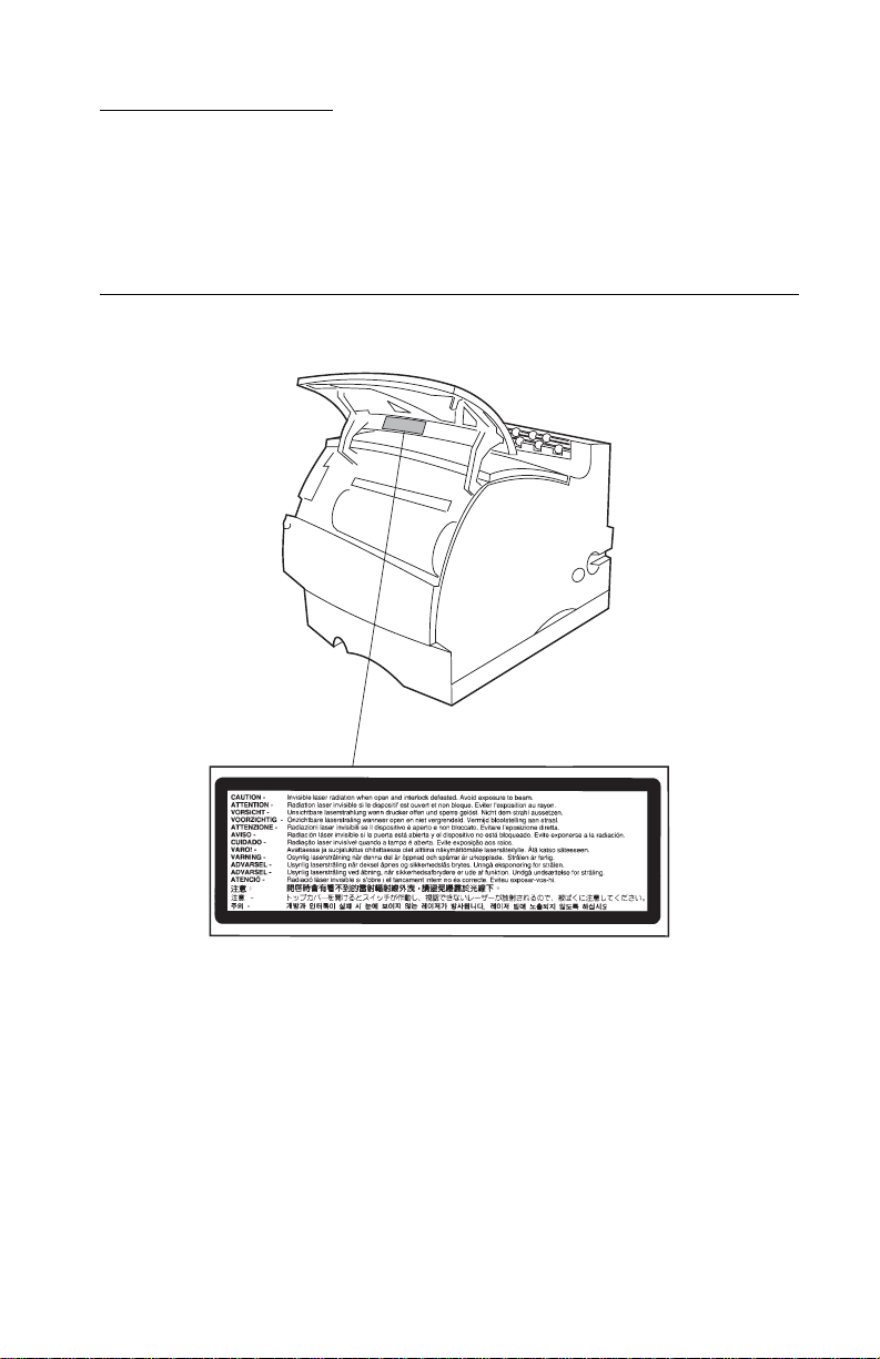
Laser Notices
The following laser notice labels may be affixed to this printer as
shown:
Laser Advisory Label
Laser Notices ix
Page 10
4069-5XX/7XX
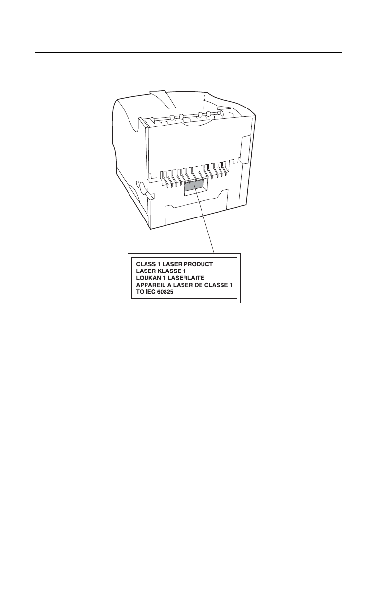
Class 1 Laser Statement Label
x Service Manual
Page 11

4069-5XX/7XX
Laser No tice
The printer is certified in the U.S. to conform to the requirements of
DHHS 21 CFR Subchapter J for Class I (1) laser products, and
elsewhere is certified as a Class I laser product conforming to the
requirements of IEC 60825.
Class I laser products are not considered to be hazardous. The
printer contains internally a Class IIIb (3b) laser that is nominally a 5
milliwatt gallium arsenide laser operating in the wavelength region of
770-795 nanometers. The laser system and printer are designed so
there is never any human access to laser radiation above a Class I
level during normal operation, user maintenance, or prescribed
service condition.
Laser
Der Drucker erfüllt gemäß amtlicher Bestätigung der USA die
Anforderungen der Bestimmung DHHS (Department of Health and
Human Services) 21 CFR Teil J für Laserprodukte der Klasse I (1).
In anderen Ländern gilt der Drucker als Laserprodukt der Klasse I,
der die Anforderungen der IEC (International Electrotechnical
Commission) 60825 gemäß amtlicher Bestätigung erfüllt.
Laserprodukt e der Klasse I gelten als unschädlich. Im Inneren des
Druckers befindet sich ein Laser der Klasse IIIb (3b), bei dem es
sich um einen Galliumar senlaser mit 5 Mi lliwat t hande lt, der Wellen
der Länge 770-795 Nanometer ausstrahlt. Das Lasersystem und der
Drucker sind so konzipiert, daß im Normalbetrieb, bei der Wartung
durch den Benutzer oder bei ordnungsgemäßer Wartung durch den
Kundendienst Laserbestrahlung, die die Klasse I übersteigen würde,
Menschen keinesfalls erreicht.
Laser Notices xi
Page 12

4069-5XX/7XX
Avis relatif à l’utilisation de laser
Pour les Etats-Unis : cette imprimante est cer tifiée conforme aux
provisions DHHS 21 CFR alinéa J concernant les produits laser de
Classe I (1). Pour les autres pays : cette imprimante répond aux
normes IEC 60825 relatives aux produits laser de Classe I.
Les produits laser de Classe I sont considérés comme des produits
non dangereux. Cette imprimante est équipée d’un laser de Classe
IIIb (3b) (arséniure de gallium d’une puissance nominale de 5
milliwatts) émettant sur des longueurs d’onde comprises entre 770
et 795 nanomètres. L’imprimante et son système laser sont conçus
pour impossible, dans des conditions normales d’utilisation,
d’entretien par l’utilisateur ou de révision, l’exposition à des
rayonnements laser supérieurs à des rayonnements de Classe I .
Avvertenze sui prodotti laser
Questa stampante è certificata negli Stati Uniti per essere conforme
ai requisiti del DHHS 21 CFR Sottocapitolo J per i prodotti laser di
classe 1 ed è certificata negli altri Paesi come prodotto laser di
classe 1 conforme ai requisiti della norma CEI 60825.
I prodotti laser di classe non sono considerati pericolosi. La
stampante contiene al suo interno un laser di classe IIIb (3b)
all’arseniuro di gallio della potenza di 5mW che opera sulla
lunghezza d’onda compresa tra 770 e 795 nanometr i. Il sistema
laser e la stampante sono stati progettati in modo tale che le
persone a contatto con la stampante, durante il normale
funzionamento, le operazioni di servizio o quelle di assistenza
tecnica, non ricevano radiazioni laser superiori al livello della classe
1.
Laser Notices xii
Page 13

4069-5XX/7XX
Avisos sobre el láser
Se certifica que, en los EE.UU., esta impresora cumple los
requisitos para los productos láser de Clase I (1) establecidos en el
subcapítulo J de la norma CFR 21 del DHHS (Departamento de
Sanidad y Servicios) y, en los demás países, reúne todas las
condiciones expuestas en la norma IEC 60825 para productos láser
de Clase I (1).
Los productos láser de Clase I no se consideran peligrosos. La
impresora contiene en su interior un láser de Clase IIIb (3b) de
arseniuro de galio de funcionamiento nominal a 5 milivatios en una
longitud de onda de 770 a 795 nanómetros. El sistema láser y la
impresora están diseñados de forma que ninguna persona pueda
verse afectada por ningún tipo de radiación láser superior al nivel de
la Clase I durante su uso normal, el mantenimiento realizado por el
usuario o cualquier otra situación de servicio técnico.
Declaração sobre Laser
A impressora está certificada nos E.U.A. em conformidade com os
requisitos da regulamentação DHHS 21 CFR Subcapítulo J para a
Classe I (1) de produtos laser. Em outros locais, está certificada
como um produto laser da Classe I, em conformidade com os
requisitos da norma IEC 60825.
Os produtos laser da Classe I não são considerados perigosos.
Internamente, a impressora contém um produto laser da Classe IIIb
(3b), designado laser de arseneto de potá ssio, de 5 milliwatts
,operando numa faixa de comprimento de onda entre 770 e 795
nanómetros. O sistema e a impressora laser foram concebidos de
forma a nunca existir qualquer possiblidade de acesso humano a
radiação laser superior a um nível de Classe I durante a operação
normal, a manutenção feita pelo utilizador ou condições de
assistência prescritas.
Laser Notices xiii
Page 14

4069-5XX/7XX
Laserinformatie
De printer voldoet aan de eisen die gesteld worden aan een
laserprodukt van klasse I. Voor de Verenigde Staten zijn deze eisen
vastgelegd in DHHS 21 CFR Subchapter J, voor andere landen in
IEC 60825.
Laserprodukt en van klasse I worden niet als ongevaarlijk
aangemerkt. De printer is voorzien van een laser van klasse IIIb
(3b), dat wil zeggen een gallium arsenide-laser van 5 milliwatt m e t
een golflengte van 770-795 nanometer. Het lasergedeelte en de
printer zijn zo ontworpen dat bij normaal gebrui k, bij onderhoud of
reparatie conform de voorschriften , nooit blootste lling mogelijk is
aan laserstraling boven een niveau zoals voorgeschreven is voor
klasse 1.
Lasermeddelelse
Printeren er godkendt som et Klasse I-laserprodukt, i
overenstemmelse med kravene i IEC 60825.
Klasse I-laserprodukter betragtes ikke som farlige. Printeren
indeholder internt en Klasse IIIB (3b)-laser, der nominelt er en 5
milliwatt galliumarsenid laser , som arbejder på bølgelængdeområdet
770-795 nanometer. Lasersystemet og printeren er udformet
således, at mennesker aldrig udsættes for en laserstråling over
Klasse I-niveau ved normal drift, brugervedligeholdelse eller
obligatoriske servicebetingelse r.
Laser Notices xiv
Page 15

4069-5XX/7XX
Huomautus laserlaitteesta
Tämä kirjoitin on Yhdysvalloissa luokan I (1) laserlaitteiden DHHS
21 CFR Subchapter J -määrityksen mukainen ja muualla luokan I
laserlaitteiden IEC 60825 -määrityksen mukainen.
Luokan I laserlaitteiden ei katsota olevan vaarallisia käyttäjälle.
Kirjoittimess a on sisäi nen luokan I IIb (3b) 5 milliwatin
galliumarsenidilaser, joka toimii aaltoalueella 770 - 795 nanometriä.
Laserjärjestelmä ja kirjoitin on suunniteltu siten, että käyttäjä ei
altistu luokan I määrityksiä voimakkaammalle säteilylle kirjoittimen
normaa lin toiminnan, käyttä jän tekemien huoltotoimien tai muiden
huoltotoimien yhteydessä.
VARO! Avattaessa ja suojalukitus ohitettaessa olet alttiina
näkymättömälle lasersäteilylle. Älä katso säteeseen.
VARNING! Osynlig laserstrålning när denna del är öppnad och
spärren är urkopplad. Betrakta ej strålen.
Laser-notis
Denna skrivare är i USA certifierad att motsvara kraven i DHHS 21
CFR, underparagraf J för laserprodukter av Klass I (1). I andra
länder uppfyller skrivaren kraven för laserprodukter av Klass I enligt
kraven i IEC 60825.
Laserprodukter i Klass I anses ej hälsovådliga. Skrivaren har en
inbyggd laser av Klass IIIb (3b) som består av en laserenhet av
gallium-arsenid på 5 milliwatt som arbetar i våglängdsområdet 770795 nanometer. Lasersystemet och skrivaren är utformade så att det
aldrig finns risk för att någon person utsätts för laserstrålning över
Klass I-nivå vid normal användning, underhåll som utförs av
användaren eller annan föreskriven serviceåtgärd.
Laser Notices xv
Page 16

4069-5XX/7XX
Laser-melding
Skriveren er godkjent i USA etter kravene i DHHS 21 CFR,
underkapittel J, for klasse I (1) laserprodukter, og er i andre land
godkjent som et Klasse I-laserproduk t i samsvar med kravene i IEC
60825.
Klasse I-laserprodukter er ikke å betrakte som farlige. Skriveren
inneholder internt en klasse IIIb (3b)-laser, som består av en
gallium-arsenlaserenhet som avgir stråling i bølgelengdeområdet
770-795 nanometer. Lasersystemet og skriveren er utformet slik at
personer aldri utsettes for laserstråling ut over klasse I-nivå under
vanlig bruk, vedlikehold som utføres av brukeren, eller foreskrevne
serviceopera sjoner.
Avís sobr e el Làser
Segons ha estat certificat als Estats Units, aquesta impressora
compleix els requisits de DHHS 21 CFR, apartat J, pels productes
làser de classe I (1), i segons ha estat certificat en altres llocs, és un
producte làser de classe I que compleix els requisits d’IEC 60825.
Els productes làser de classe I no es consideren perillosos. Aquesta
impressora conté un làser de classe IIIb (3b) d’arseniür de gal.li,
nominalment de 5 mil.liwats, i funciona a la regió de longitud d’ona
de 770-795 nanòmetres. El sistema làser i la impressora han sigut
concebuts de manera que mai hi hagi exposició a la radiació làser
per sobre d’un nivell de classe I durant una operació normal, durant
les tasques de manteniment d’usuar i ni durant els serveis que
satisfacin les condicions prescrites.
Laser Notices xvi
Page 17
4069-5XX/7XX
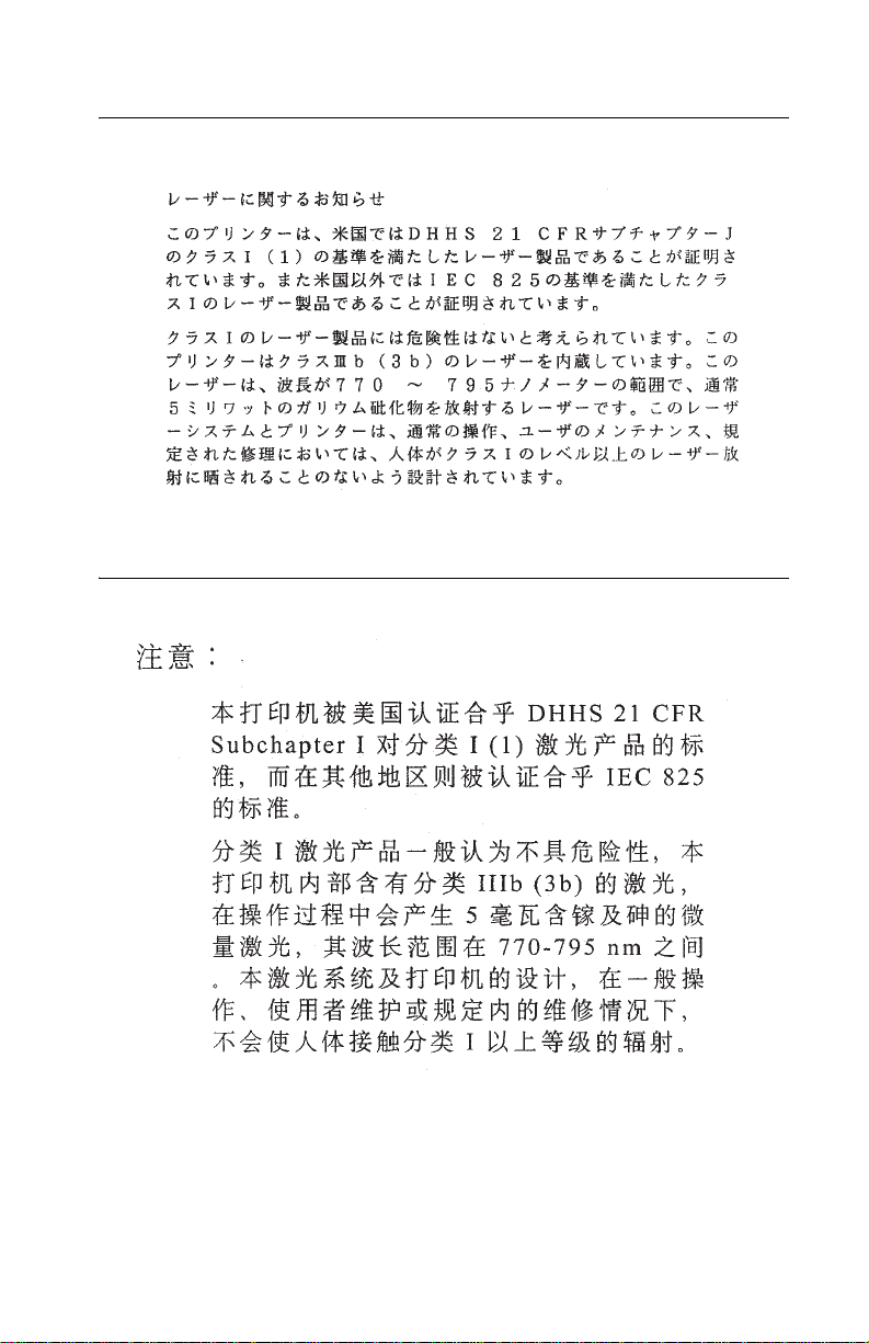
Japanese Laser Notice
Chinese Laser Notice
Laser Notices xvii
Page 18
4069-5XX/7XX
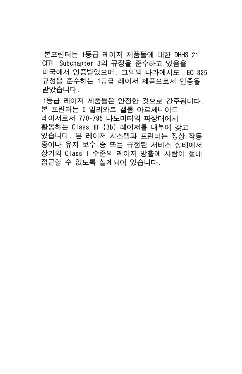
Korean Laser Notice
xviii Service Manual
Page 19

4069-5XX/7XX
Safety Information
• This product is designed, tested and approved to meet strict
global safety standards with the use of specific Lexmark
components. The safety features of some parts may not always
be obvious. Lexmark is not responsible for the use of other
replacement par ts.
• The maintenance information for this product has been
prepared for use by a professional service person and is not
intended to be used by others.
• There may be an increased risk of electric shock and personal
injury during disassembly and servicing of this product.
Professional service personnel should understand this and take
necessary precaut ions.
Consignes de Sécurité
• Ce produit a été conçu, testé et approuvé pour respecter les
normes strictes de sécur ité globale lors de l'utilisation de
composants Lexmark spécifiques. Les caractéristiques de
sécurité de certain s élémen ts ne sont pas toujours évidente s.
Lexmark ne peut être tenu responsable de l'utilisation d'autres
pièces de rechange.
• Les consignes d'entretien et de réparation de ce produit
s'adressent uniquement à un personnel de maintenance
qualifié.
• Le démontage et l'entretien de ce produit pouvant présenter
certains r isques électr iqu es, le personnel d'entretien qualifié
devra prendre toutes les précautions nécessaires.
Safety In fo rmation xix
Page 20

4069-5XX/7XX
Norme di sicurezza
• Il prodotto è stato progettato, te stato e approvato i n conf ormità a
severi standard di sicurezza e per l’utilizzo con componenti
Lexmark specifici. Le caratteristiche di sicurezza di alcune parti
non sempre sono di immediata comprensione. Lexmark non è
responsabile per l’utilizzo di parti di ricambio di altri produttori.
• Le informazioni riguardanti la manutenzione di questo prodotto
sono indirizzate soltanto al personale di assistenza autorizzato.
• Durante lo smontaggio e la manutenzione di questo prodotto, il
rischio di subire scosse elettriche e danni alla persona è più
elevato. Il personale di assistenza autorizzato, deve, quindi,
adottare le precauzioni necessarie.
Sicherheitshinweise
• Dieses Produkt und die zugehörigen Komponenten wurden
entworfen und getestet, um beim Einsatz die weltweit gültigen
Sicherheitsanforderungen zu erfüllen. Die sicherheitsrelevanten
Funktionen der Bauteile und Optionen sind nicht immer
offensichtlich. Sofern Teile eingesetzt werden, die nicht von
Lexmark sind, wird von Lexmark keinerlei V erantwortung oder
Haftung für dieses Produkt übernommen.
• Die Wartungsinformationen für dieses Produkt sind
ausschließlich für die Verwendung durch einen
Wartungsfachmann bestimmt.
• Während des Auseinandernehme ns und der Wartung des
Geräts besteht ein zusätzliches Risiko eines elektrischen
Schlags und körperlicher Verletzung. Das zuständige
Fachpersonal sollte entsprechende Vorsichtsmaßnahmen
treffen.
xx Service Manual
Page 21

4069-5XX/7XX
Pautas de Seguridad
• Este producto se ha diseñado, verificado y aprobado para
cumplir los más estrictos estándares de seguridad globa l
usando los componentes específicos de Lexmark. Pu ede que
las características de seguridad de algunas piezas no sean
siempre evidentes. Lexmark no se hace responsable del uso de
otras piezas de recambio.
• La información sobre el mantenimiento de este producto está
dirigida exclusivamente al personal cualificado de
mantenimiento.
• Existe mayor riesgo de descarga eléctrica y de daños
personales durante el desmontaje y la reparación de la
máquina. El personal cualificado debe ser consciente de este
peligro y tomar las precauciones necesarias.
Informações de Segurança
• Este produto foi concebido, testado e aprovado para satisfazer
os padrões globais de segurança na utilização de componentes
específicos da Lexmark. As funções de segurança de alguns
dos componentes podem não ser sempre óbvias. A Lexmark
não é responsável pela utilização de outros componentes de
substituição.
• As informações de segurança relativas a este produto
destinam-se a profissionais destes serviços e não devem ser
utilizadas por outras pessoas.
• Risco de choques eléctricos e ferimentos graves durante a
desmontagem e manutenção deste produto. Os profissionais
destes serviços devem estar avisados deste facto e tomar os
cuidados necessários.
Safety In fo rmation xxi
Page 22

4069-5XX/7XX
Inf ormació de Seguretat
• Aquest producte està dissenyat, comprovat i aprovat per tal
d'acomplir les estrictes nor me s de seguretat globals amb la
utililitzac ió de components específics de Lexmark. Les
característiques de seguretat d'algunes peces pot ser que no
sempre siguin òbvies. Lexmark no es responsabilitza de l'us
d'altres peces de recanvi.
• La informació pel manteniment d’aquest producte està
orientada exclusivament a professionals i no està destinada a
ningú que no ho sigui.
• El risc de xoc elèctric i de danys personals pot augmentar
durant el procés de desmuntatge i de servei d’aquest producte.
El personal professional ha d’estar-ne assabentat i prendre les
mesures convenients.
xxii Service Manual
Page 23
4069-5XX/7XX
Safe ty In formation xxiii
Page 24

4069-5XX/7XX
Preface
This book is designed for service personnel. It is divided into the
following chapters:
1. General Informati on contains a general description of the
printer and the maintenance approach used to repair it. Special
tools and test equipment are listed in this chapter, as well as
general environmental and safety instructions.
2. D iagnostic Information contains an error indicator table,
symptom tables, and service checks used to isolate failing field
replaceable units (FRUs).
3. D iagnostic Aids contains tests and checks used to locate or
repeat symptoms of printer problems.
4. Repair Information provides instructions for making printer
adjustments and removing and installing FRUs.
5. Connector Locations uses illustrations to identify the
connector locations and test points on the printer.
6. Preventive Maintenance contains the lubrication specifications
and recommendations to prevent problems.
7. Parts Catalog contains illustrations and part numbers for
individual FRUs.
xxiv Service Manual
Page 25

4069-5XX/7XX
1. Gen e r a l Informat io n
The Lexmark™ T laser printers are letter quality page printers
designed to attach to IBM-compatible PC’s and to most computer
networks.
The Lexmark T laser printer is available in the following models.
Model Name T ype
Lexmark T620 4069-520
Lexmark T620n 4069-52n (Network)
Lexmark T622 4069-722
Lexmark T622n 4069-72n (Network)
General Information 1-1
Page 26

4069-5XX/7XX
Options
The following options are available. Some options are not available
in every country. Contact y our point of purchase for options available
in your country.
Memory options of 4MB, 8MB, 16MB, 32MB, 64MB and 128MB
SDRAM Card Assembly
Flash memory options of 2MB, 4MB , 8MB and 16M B Card Assembly
Integrated network options
Token-Ring
Ethernet
Tri-Port Adapter
IR Adapter
IPDS Card Assembly and SCS/TNe
PRESCRIBE Card Assembly
TIFF Card Assembl y
Bar Code Card Assembly
Par allel Interface Card
SCS
USB/Parallel Port
MarkNet™ Print Servers
ImageQuick Card Assembly
250 and 500-sheet paper trays of A5, letter, and legal size
250 Sheet Special Media Tray Assembly
500 Sheet Special Media Tray
2000 Sheet High Capacity Feeder
Envelope Feeder
Duplex Option - 250 Sheet
Duplex Option - 500 Sheet
Hard Disk - 5. 0+ GB
Optra Forms™ Hard Disk - 5.0+ GB
Vertical Kiosk Presenter
Horizontal Kiosk Pres enter
Output Expander
5-Bin Mailbox
High-Capacity Out put Stacker
StapleSmart™ Finisher Option
1-2 Service Manual
Page 27

4069-5XX/7XX
Maintenance Approach
The diagnostic information in this manual leads you to the correct
field replaceable unit (FRU) or part. Use the service error codes,
user status messages, user error messages, service checks, and
diagnostic aids to determine the printer problem and repair the
failure. After you complete the repair, perform tests as needed to
verify the repair.
Tools Required for Service
Flat-blade screwdriver
#1 Phillip s scr ewdriver
#2 Phillip s scr ewdriver
T10 Torx screwdriver
7.0 mm nut driver
5.5 mm wrench
Needlenose pliers
Diagonal pliers
Spring hook
Feeler gauges
Analog or digital multimeter
Parallel wrap plug 1319128
Serial wrap plug 1329048
Twinax/serial debug cable 1381963
Coax/serial debug cable 1381964
General Information 1-3
Page 28

4069-5XX/7XX
Acronyms
CSU Customer Setup
DIMM Dual In-Line Memory Module
DRAM Dynamic Random Access Memory
EDO Enhanced Data Out
EP Electrophotographic Process
EPROM Erasable, Programmable Read-Only
Memory
ESD Electrostatic Discharge
FRU Field Replaceable Unit
GB Gigabyte
HVPS High Voltage Power Supply
LASER Light Amplification by Stimulated Emission
of Radiation
LCD Liquid Cr ysta l Display
LED Light-Emitting Diode
LVP S Low Voltage Power Supply
MROM Masked Read Only Memor y
NAND
NVRAM Nonvolatile Random Access Memory
OEM Original Equip men t Manufacturer
PC Photoconductor
POR Power-On Reset
POST Power-On Self Test
RIP Raster Imaging Processor
ROM Read Only Memory
SDRAM Synchronous Dual Random Access
Memory
SRAM S t atic Random Ac cess Memo ry
UPR Used Parts Return
V ac Vol ts alternating current
V dc Vol ts direct current
1-4 Service Manual
Page 29

4069-5XX/7XX
2. Diagnostic Information
Start
CAUTION: Remove the power cord from the printer or wall outlet
before you connect or disconnect any cable or electronic board or
assembly for personal safety and to prevent damage to the printer.
Use the handholds on the side of the printer. Make sure your fingers
are not under the printer when you lift or set the printer down.
Use the service error code, user status message, user error
message, symptom table, service checks, and diagnostic aids in this
chapter to determine the corrective action necessary to repair a
malfunctioning printer.
Service error codes are indicated by a three-digit error code. If a
service error code is displayed, go to the “Service Error Codes” on
page 2-2.
User status messages provide the user with information on the
current status of the printer. Ready is displayed on the first line of the
display unless Power Saver is invoked, and then Power Saver is
displayed. If a user status message is displayed, go to the “ U ser
Status Screens” on page 2-24.
User error messages are indicated by a two or three-digit error code
that provides the user with information that explains a problem with a
print cartrid ge, paper jam, option, por t , and so on. If a user error
message is displayed, go to the “User Attendance Messages” on
page 2-29.
If your machine completes the “Power-On Self Test (POST)” on
page 2-41 without an error, and you have a symptom, go to the
“Symptom Tables” on page 2-42. Locate your symptom and take
the appropriate action.
If a service error code appears while you are working on the
machine, go to the “Service Error Codes” on page 2-2 and take
the indicated action for that error.
Diagnostic Information 2-1
Page 30

4069-5XX/7XX
Service Error Codes
Service Error Codes are generally non-recoverable except in an
intermittent condition when you can POR the printer to temporarily
recover from the error condition.
Error Code Action
900 RIP Software Contact the next support level or call Lexmark.
901 Engine Flash Indicates that the flash which the engine code is
902 General
Engine Software
903 Paperport
Link Driver Error
904 Interface
Violation by the
controller
software
905 Interface
Violation by
Paperport Device
906 ControllerEngine Link
Driver Error
910 DC Pick
Motor DC Pick
Motor Stall
911 DC Pick
Motor E xcessi ve
PWM
programmed into is bad. Replace the syst em board.
These errors indicate an unrecoverable engine software
error. Replace the system boar d.
Check for correct location of the jumpers on the
interconnect board for the model/type printer you are
servicing. Incorrect jumper settings can cause a 902
service error. If jumpers are set correctly, replace the
system board.
Error Codes 910,911,912,913 and 914 are indications
that a Tray 1 paper feed problem has been detected. Go
to the “Input Tray(s) Option Service Check” on
page 2-69.
912 DC Pick
Motor below
speed
913 DC Pick
Motor over speed
2-2 Service Manual
Page 31

4069-5XX/7XX
Error Code Action
914 DC Pick
Moto r: No
encoder feedback
917 Transfer Roll Indicates a problem in the transfer roll area. Go to t he
920 Fuser Error Indicates that the fuser is below temper ature when
921 Fuser Error Indicates that the fuser is below standby temperature
922 Fuser Error Fuser failed to reach standb y temperature . Go to the
923 Fuser Error Fuser is too hot durin g print ing or when printer i s idle. Go
924 Fuser Error An open circuit has been detected in the Fuser
Check the integ rat ed paper tr a y (tra y 1) f or cor rect pape r
loading. Reload the paper and POR the printer. If the
error continues, go to the “Input Tray(s) Option
Service Check” on page 2-69.
“T ransfer Roll Service Check” on page 2-123.
printing. Go to the “Cold Fuser Service Check” on
page 2-65. Use of the “Base Printer (Fuser) Sub Err or
Codes” on page 2-17 may help diagnose fuser failure.
when the printer is idle. Go to the “Cold Fuser Service
Check” on page 2-65. Use of the “Base Printer
(Fuser) Sub Error Codes” on page 2-17 may help
diagnose fuser failure .
“Cold Fuser Service Ch eck” on page 2-65. Use of the
“Base Printer (Fuser) Sub Error Codes” on
page 2-17 may help diagnose fuser failure.
to the “Hot Fuse r S ervice Check” on pa ge 2-67. Use
of the “Base Printer (Fuser) Sub Error Codes” on
page 2-17 may help diagnose fuser failure.
Thermistor Circuit. Go to the “Hot Fuser Service
Check” on page 2-67. Use of the “Base Printer
(Fuser) Sub Error Codes” on page 2-17 may help
diagnose fuser failure .
925 Fuser Error 1. Indicates the wrong fuser lamp is installed. Check the
fuser lamp for the correct type of lamp that should be
installed.
2. Check the line voltage to ensure it is not above the
maximum rating for the printer.
3. This error may also indicate t he fuser reached standby
temperature too quickly.
4. The hot roll may not be correct f or t his fuser. Ensure
that the correct hot roll is installed.
927 Fan Stall ed Indicates a printe r f an stalled. Go to the “Fan Service
Check” on page 2-63.
Diagnostic Information 2-3
Page 32

4069-5XX/7XX
Error Code Action
929 T one r Sensor The t oner se nsor is not operat ing pr operly, the devel oper
drive assembly is not operating properly or the print
cartridge is defective. Go to the “Toner Sensor Service
Check” on page 2-122.
930 Printhead
Error
932-935
Printhead Error
932 Printhead
Error
933 Printhead
Error
934 Printhead
Error
935 Printhead
Error
936-937
Transport Motor
936 - Main Drive
Motor init ia l lo ck
failure
937 - Main Drive
Motor los t lo ck
939 RIP-Engine
Communications
Lost
The wrong printhead is installed. Replace with the
correct printhead.
These errors represe nt a prob le m with the printh ead. Go
to the “Printhead Service Check” on page 2-108.
Indicates a pr oblem with the main drive motor. Go to the
“Main Drive Service Check” on page 2-85.
The RIP and engine cannot communi cate with one
another. The system board or Int erconnect board is
defective. Check for correct installation. If no problem is
found, replace the FRUs in the following order:
2-4 Service Manual
System Board
Interconnect Board
Note: If a problem stil l exists, the RIP software can
cause a 939 error code. Contact your ne xt level for
software support.
Page 33

4069-5XX/7XX
Error Code Action
940 Service LV
Power Supply
947 PQET Error Indicates that the PQET RAM test was incomplete or a
948 PEL Clock
Error
949 Delay Line
Calibration
Failure
953 - 954
NVRAM Failure
The low voltage power supply zero crossover test failed.
• Check the LVPS for correct instal lat ion. Ensure that
the connector on the LVPS assembly is firmly seated
with the c onnector on the interconnect card connec tor.
• This error can be caus ed by a noisy AC input power
source.
• Check to mak e sure the correct LVPS has been
installed.
• If all the above are correct, replace the LVPS
assembly.
PQET RAM test busy failure occurr ed. Replace the
system board.
Indicates the PEL clo ck check failed. Replace the
system board.
Indicates a delay line calibration failure. Replace the
system board.
System board failures.
953 NVRAM Chip Failure
954 NVRAM CRC Failure
Replace system board.
955 Code CRC
<loc>
Code ROM and NAND failed CRC check
*<loc> = F or a R OM CRC f ai lure , the l ocati on (loc) will be
a failing block or (B n).
*<loc> = For a NAND CRC failur e, the location (loc) will
be a failing page or (Pn).
Replace System Board.
Diagnostic Information 2-5
Page 34

4069-5XX/7XX
Error Code Action
956, 957, 959
System Board
958 NAND
Failure
960 - 963 RAM
Memory Error
Error codes 956 thru 959 are system board failures.
Perform a power on reset (POR). If this does not fix the
problem, replace the system board.
*956 = Processor Failure
*957 = ASIC Failure
*959 = SRAM Failure
Before proc eeding when a 958 NAND failure is
displayed, perform a Power On Reset (power the printer
Off then On) to see if the ECC (Error Correc ti on Code)
can reflash NAND.
If this does not fix the problem, repl ace the system
board.
Error codes 960 thru 963 indic ate the follo wing specific
RAM error:
*960 - RAM soldered on the syst em board is failing.
Replace the system board.
*961 - RAM in slot 1 is fai li ng.
*962 - RAM in slot 2 is failing
*963 - RAM in slot 3 is fai li ng.
For error s 961 thru 963, if a v ail able , swit ch memory from
the failing slot with one from a non-f ailing slot to see if it
fixes the problem. If it does fix the problem, replace the
system board. If this fixes the problem, replace the
defecti ve RAM.
964 Emulation
Error
2-6 Service Manual
Download Emulation CRC f ailure has occurred.
Page 35

4069-5XX/7XX
Error Code Action
975 - 979
Network Card X
980 - 984 Service
<device> Comm.
The foll owing errors indicate a failure with t he network
card in the speci fi ed slot. X=any card installed in slots
1,2 or 3. 975 - Unrecognizab le Network Card x. Replace
Network Card x.
976 - Unrecoverable software error in Network Card x.
977 - Controller sof tware detects that a Network Card is
installed in slot x but cannot est ablish communi cations
with it.
978 - Bad checksum whil e programming Network Card
x. Replace Network Card x.
979 - Flash parts failed while programming Network
Card x.
If the printer is a network model, replace the system
board.
These error codes indicate the specified device
<device> has detected a paper port failure.
Specified device <device> can be one of the following:
*System Board
*Duplex
*Tray x (x = 1,2,3,4 or 5)
*Env elope Feeder
*Output Bin x (x = 1,2,3 to 6)
**Will be displayed f or single bin outpu t opt ions.
*Output Bins x to y (x to y = 1 to 5, 2 to 6, 6 to 10)
**Will be displayed for multiple bi n output options.
980 = The engine is experiencing unreliable
communicat ions to the specified device.
981 = Engine pr otocol viol atio n ha s b een det ected b y the
specified device.
982 = Communications error detected b y the specified
device.
983 = Invalid command received by the specified device.
984 = Invalid command paramete r rec eived by the
specified device.
Diagnostic Information 2-7
Page 36

4069-5XX/7XX
Error Code Action
990 Service
<device>
991 Service
<device> Card
This error will be displayed when an equipment check
condition has occ u rr ed in the specified device
(<device>), but the device is unable to identify the exact
component failure.
Specified de vice <devi ce> can be one of the follo wing:
*System Board
* Duplex
*Tray x (x = 1,2,3,4 or 5)
*Env elope Feeder
*Output Bin x (x = 1,2,3 to 6)
**Will be dis p layed for sin gl e bin ou tp u t o ptio n s.
*Output Bins x to y (x to y = 1 to 5, 2 to 6, 6 to 10)
**Will be dis p layed for multip le b in outp u t op t io n s.
*StapleSmart Finisher Option
This message will be displ ayed when the specified
device has detected an equipment check in its system
card.
Specified de vice <devi ce> can be one of the follo wing:
* Duplex
*Tray x (x = 1,2,3,4 or 5)
*Env elope Feeder
*Output Bin x (x = 1,2,3 to 6)
**Will be dis p layed for sin gl e bin ou tp u t o ptio n s.
*Output Bins x to y (x to y = 1 to 5, 2 to 6, 6 to 10)
**Will be dis p layed for multip le b in outp u t op t io n s.
*StapleSmart Finisher Option
Sub Error Codes for 9XX and 2XX Error Codes
The sub error codes are helpful troubleshooting a paper path
problem, especially paper jams in the base printer, envelope feeder
and duplex unit.
When a 9XX or 2XX error displays:
1. Press and hold Retur n and press Select to enter for sub error
codes.
2. The first screen of information is displayed. Write down the
information.
2-8 Service Manual
Page 37

4069-5XX/7XX
3. Continue pressing Return and Select until each screen of
information is obtained.
4. When the last screen displays, the original message displays.
The following is an example of how the printer shows a duplex unit
sub error code.
DU
DU
Byte 1
XX
XX
Byte 5
Byte 2
XX
XX
Byte 6
Byte 3
XX
XX
Byte 7
Byte 4
XX
XX
Byte 8
Diagnostic Information 2-9
Page 38

4069-5XX/7XX
Base Printer Sub Error Codes
Each status byte has a different level of troubleshooting value for
each area of the printer. The following table displays up to 8 status
bytes of data. Some or all of these bytes may be used to help
diagnose a printer problem. These status bytes are designed to help
isolate paper jams and paper feed problems in the base printer
Legend for Tray Source: x=10 (MPT), x-11 (Tray 1), x=12, (Tray 2),
x=13 (Tray 3), x-14 (Tray 4), x=15 (Tray 5), x=31 (Env Feeder), X=40
(Manual)
Legend for Stacker Destination: x=91 (Stacker 1), x=92 (Stacker 2),
x-93 (Stacker 3)
Legend for media size: x=1 (letter), x=2 (legal), x=3 (B5), x=4 (A4),
x=5 (Executive), x=6 (A5), x=7 (Custom), x=9 (73/4 Env), A-#9 Env,
B-#10 Env, C=8.661” Env, D=C5 Env, E=B5 Env, F=Legal Env.
First 6
Bytes Sub
Error Code
Data - N o te:
xx can be
any value.
Explanation
84 xx 00 x1 x2This code indicates that the input sensor in the printer is still
actuated fro m the fi rst she et and the seco nd shee t is ready t o
arrive at the sensor.
(x1=media size, x2=media source)
*Check the pri nter i nput senso r and fl ag fo r cor rect operat ion.
The flag should operate freely.
*Check for any signs of debris in the area of the input sensor.
*Check the area of the tr ansf e r plate and input t o the fuse r f or
anything that might cause the paper to remain over the
input sensor.
84 xx 01 x1 Video never started on the page.
(x-1=media size)
*The video signal never started within 2 in ches after
actuating the input sensor. Check input sensor and flag.
2-10 Service Manual
Page 39

4069-5XX/7XX
First 6
Bytes Sub
Error Code
Data - Note :
xx can be
any value.
84 xx 02 x1 This error is the most common type of paper jam. Possible
Explanation
causes are (x1=media size):
*Multi sheet feeding.
*A tray size sensing problem.
*The media feeding from the paper source is sli pping or
media is slipping in input to the printer.
84 xx 04 The input sensor was covered during POST by a piece of
84 xx 05 There was a media at the input sensor too early. There w as
84 00 06 A paper jam has been declar ed b y a s mart de vice . Immed iate
84 00 07 A paper jam has been declared by a smart device. Homing
84 xx 0B x1
x2 x3
media still in the machine when it was turned on.
*Clear the media from the printer.
*Run the base sensor test (input sensor) from the diagnostic
tests menu to test the input sensor and flag f or correct
operation.
not enough time between printhead start and the printhead
mirror motor to lock. Possible causes for this error are:
*Paper might be pre-staged in the paper source tray.
*Paper is picking too fast.
*A defective input sensor.
stop homing not allowed.
was allowed before the stop.
The option tra y pass thru sensor was ne ver actuated by a
piece of media. (x-1=media size) (x-2=media source) (x3=paper source where paper jam was detected)
*Run the sensor test for the option tray that is displaying the
error code and check the pass thru sensor for t hat tray for
correct operation.
*Check for paper picking from the selected paper input
source.
*If the erro r i s being detected from a lower paper source, see
if paper is feeding correctly from a paper source abov e the
detected source.
Diagnostic Information 2-11
Page 40

4069-5XX/7XX
First 6
Bytes Sub
Error Code
Data - N o te:
xx can be
any value.
Explanation
84 xx 0f x1
x2 x3
84 00 10 The main motor ID failed to identify either motor after two
84 xx 17 There is an envelope or envelopes in the envelope feeder
84 xx 18 There is media over the Tray 2 pass thru sensor during warm-
84 xx 19 There is media over the Tray 3 pass thru sensor during warm-
The option Tray pass thru sensor was never deactivated.
(x-1=media size) (x-2=media source) (x-3=media source
where paper jam was detected)
*Check the pass thru sensor and flag f or correct operation.
*Check to see if paper has cleared the pass thru area of the
option where the pap er j am oc curred.
tries. Possible causes for this error are:
*The main drive motor has stalled.
*An incorrect main dri ve motor/gearb ox assembly has been
installed.
during warm-up. An envelope may have partially fed from the
envelope feeder.
*Remove any envelopes from the feeder and check the
envelope feeder for correct operation.
up. Check for media o ver the sensor. If no media is presen t,
check the pass thru sensor, flag, and cables.
*Try running the Input Tray Tests for Tray 2 and see if Tray 2
is feedi ng paper correctly and al l th e sensors are working
correctly.
*Check to mak e sure the paper size setting is correct for the
size paper in the tr ay.
up. Check for media o ver the sensor. If no media is presen t,
check the pass thru sensor, flag, and cables.
*Try running the Input Tray Tests for Tray 3 and see if Tray 3
is feedi ng paper correctly and al l th e sensors are working
correctly.
*Check to mak e sure the paper size setting is correct for the
size paper in the tr ay.
2-12 Service Manual
Page 41

4069-5XX/7XX
First 6
Bytes Sub
Error Code
Data - Note :
xx can be
any value.
84 xx 1A There is media over t he Tray 4 pass thru sensor during warm-
84 xx 1B There is media over t he Tray 5 pass thru sensor during warm-
Explanation
up. Check for media ov er the sensor. If no media is present,
check the pass thru sensor, flag, and cables.
*Try running the Input Tray Tests for Tray 4 and see if Tray 4
is feeding paper correctly and all the sensors are working
correctly.
*Check to mak e sure t he paper size setting is cor rect for the
size paper in the tray.
up. Check for media ov er the sensor. If no media is present,
check the pass thru sensor, flag, and cables.
*Try running the Input Tray Tests for Tray 5 and see if Tray 5
is feeding paper correctly and all the sensors are working
correctly.
*Check to mak e sure t he paper size setting is cor rect for the
size paper in the tray.
84 xx 1C There i s media over the Tray 6 pass thru sensor during warm-
84 xx 1D The envel ope f e eder pa ss thru sen sor ne v er deacti vat ed. The
84 xx 1E x1 x2The envelope feeder pass thru sensor was nev er activated.
up. Check for media ov er the sensor. If no media is present,
check the pass thru sensor, flag, and cables.
*Try running the Input Tray Tests for Tray 6 and see if Tray 6
is feeding paper correctly and all the sensors are working
correctly.
*Check to mak e sure t he paper size setting is cor rect for the
size paper in the tray.
display of this code indicates that an envelope nev er crossed
over the sensor flag and passed beyond the sensor, or the
flag and sensor are not operating properly. Go to the
“Envelope Feeder Option Service Check” on page 2-56.
(x1=Media Size , x2=Media Source)
Ensure that envelopes are fe eding over the sensor. If an
envelope feeds over the sensor but the sensor does not
activate, check the sensor and flag for cor rect operation. If
the sensor and flag are operating correctly, go to the
“Envelope Feeder Option Service Check” on page 2-56.
Diagnostic Information 2-13
Page 42

4069-5XX/7XX
First 6
Bytes Sub
Error Code
Data - N o te:
xx can be
any value.
84 xx 20 x1 x2The imaged page is not the e xpected page.
Explanation
(x1=Media Size, x2=Media Source)
Check the pass thru sens or to make sure it is operating
properly. If no problem is found, it may be necessary to try a
new pass thru sensor.
84 xx 21 x1 x2The smart tray x did not pick a sheet of paper.
84 xx 22 x1 x2This code indi cates that the media activat ed the input sensor
84 xx 23 x1 x2The transfer servo never started.
84 xx 25 This code indicates that the media has activated the input
84 xx 26 This code indicates that media has activated the input
(x1=Media Size, x2=Media Source)
Check tray x auto compensato r and tr ay parts for correct
operation. If no problem is found, go to the “Input Tray(s)
Option Service Check” on page 2-69.
before the printer EP was ready.
(x1=Leading Edge of Medi a State , x2=Trailing Edge of Media
State)
(x1=Media Size, x2=Leading Edge of Media State)
sensor before the printhead has locked. Enough time has
elapsed since printhead start to expect a lock.
One of the following may be failing:
*Printhead Assembly
*System Board
*Printhead Cables
sensor; howe v er , the print head f el l out o f loc k c ondition o r not
enough time elapsed si nce the printhead start to expect a
stable loc k. The media may have also reached the input
sensor early.
2-14 Service Manual
Page 43

4069-5XX/7XX
First 6
Bytes Sub
Error Code
Data - Note :
xx can be
any value.
89 00 01 The exit sensor in the fuser is activated by a piece of media
89 xx 03 The fuser exit sensor did not detect the trailing edge of the
Explanation
indicating there is a piece of media in the machine during
POST.
*Check for media in the exit of the fuser assembly or redrive
assembly. Feed a sheet of paper, and if the same error
occurs after clearing the fuser or the same error occurs
when no media is present, check the exi t sensor assembly,
internal fuser assembly cabling, DC fuser cable to the
system board, and the cable connection t o J14 on the
system board.
TIP: Turn the printer off, enter the diagnostic tests menu, and
select the base sensor test. Select output sensor and check
the sensor for correct operation.
media going through the fuser assembly.
*This failure can be caused by a brok en fuser exit sensor
flag.
*This may also be caused by erratic operation of exit sensor
flag or exit sensor or a defecti ve piece of media.
89 xx 04 x1 The fuser exit sensor never actuated from the sheet going
through the fuser before the next page begins fee ding.
(x-1=Media Size)
89 xx 07 The narrow media sensor in t he fuser was cov er ed b y a shee t
of paper when not expec ted or a piece of media is in the
machine during POST.
*This error can occur when a 202 paper jam has occurred.
*Remove any piece of media that is over the narrow media
sensor.
*Try to feed a piece of paper through the printer (coul d run
the print test from the diagnostic test menu). If the media
stops over the narrow media sensor again, check the flag
and sensor for cor rect operation.
89 xx 0B x1 The fuser exit sensor may be bouncing.
*This error can be cause d by a failing exit sensor or system
board.
Diagnostic Information 2-15
Page 44

4069-5XX/7XX
First 6
Bytes Sub
Error Code
Data - N o te:
xx can be
any value.
89 xx 0D The fuser exit sensor bounced. Check the exit sensor for
Explanation
correct oper ati on. Check the fuser DC cable to J14 on the
system board. Also, the sys tem board may be failing.
8D 00 00 The fuser e xit sensor was never activated by the leading
8E xx 02 x1 x2This error can be caused by the input sensor not being
8E xx 06 x1 The second pick failed from a paper source when paper was
8E xx 07 x1 The second pick failed from a paper source when paper was
8E xx 08 The paper in the output bin was flushed. The paper ahead of
edge of the media f ed through the printer.
*This error can be displaye d after a 201 paper jam.
*This can be caused by a defective fuser exit sensor
assembly.
Enter the diagnos ti c tests menu, select base sensor tests,
select output sensor test and check the f user exit sensor for
correct operation. If the test fails, check the internal fuser
cabling, DC autoconnect on the fuser frame, fuser DC
autoconnect to t he system board cable , and the cable
connection to J14 on the system board.
activat ed by a page th at w as know n to hav e bee n pick e d by a
source other than the duplex option.
*Ensure the correct source has been sele cted and the medi a
is feedi ng from that source.
in the source and the only sheet in the paper path.
in the source. Other sheets may have started to fe ed, but
none were in the paper path.
it, in the paper path, never made it past the output bin sensor
or into the tray.
8E xx 09 x1 The second pick from the MPT, Tray 1 or feeder fail ed when
8E xx 0A x1 The second pick fr om the MPT, Tra y 1 or feeder failed when
paper was in the sour ce. Other sheets ma y be in the paper
path.
(x1=Media Source)
paper was in the sour ce. Other sheets ma y have started to
pick, but none were in the paper path.
x1=Media S ource)
2-16 Service Manual
Page 45

4069-5XX/7XX
First 6
Bytes Sub
Error Code
Data - Note :
xx can be
any value.
8E x1 0B The DC auto compensator failed or stalled when trying to
8E xx 11 It took too long for the DC auto compensator motor to come
Explanation
feed a sheet of media.
up to speed.
8E xx 13 x1 x2Late feedin g from a paper source i nt erf ered wi th the next pick
retry. (x-1=Media Size)(x-2=Media Source)
Base Printer (Fuser) Sub Error Codes
The following Sub Error Codes could be a help in diagnosing
Fuser Assembly failures:
First 6
Bytes Sub
Error Code
Data - Note:
xx can be
any value
920 Service - Fuser Error (Under temperature while printing)
EN 08 xx yy
- 1
EN- zz - - 2
Explanation
xx=Actual Fuser Temperature
yy=The tempera ture that the fuser wan ts t o reach.
When zz=00 The Hot Roll took too long to heat up.
zz=01 The Hot Roll fell too far below the desired
temperature while printing.
zz=02 The Hot Roll was too cool while the system was
doing some checking.
zz=03 The Hot Roll was too cool when heat ing to the
desired temperature.
921 Service - Fuser Error (Fuser under t em perature while at standby)
Diagnostic Information 2-17
Page 46

4069-5XX/7XX
First 6
Bytes Sub
Error Code
Data - Note :
xx can be
any value
Explanation
EN 41 xx yy
-- 1
EN -- zz -- -2
922 Service - Fuser Error (Fuser failed to reach standby temperature)
EN 42 xx yy
-- 1
EN z1 z2 -- -
- 2
923 Service - Fuser Error (Fuser over temperature)
xx=Actual Fuser Temperature
yy=The temperature that the fuser wants to reach.
zz=00 The fuser temper atur e did not change enough from the
fuser lamp temper ature at turn on.
01 The fuser t emper atur e rose more than des ired f r om the
fuser temperature at turn on.
xx=Actual Fuser Temperature
yy=The temperature that the fuser wants to reach.
zz=00 The fuser temper atur e did not change enough from the
fuser lamp temper ature at turn on.
01 The fuser t emper atur e rose more than des ired f r om the
fuser temperature at turn on.
z2=00 The Hot Roll did not reac h standb y tempe rature in time
during sta nd by.
01 The Hot Roll took to o long t o reac h t he begin ning l amp
detection t em perature.
02 The Hot Roll reached ‘fina l l amp detection
temperature’ but took longer than expected.
03 The Hot Roll timed out trying to reach the ‘f inal lamp
detection t em perature.’
04 After Hot Roll lamp detection, did not reach steady
state contr ol i n ti m e.
05 The Hot Roll did not reach opera ting temperature in
time.
EN 12 xx yy
-- 1
EN -- -- -- -2
924 Service - Fuser Error (Open Thermistor Failure)
EN 18 xx -- -
- 1
EN -- 00 -- -2
This sub error code is di splayed anytime that the Hot Roll has
reached a higher t han desired temperatur e.
xx=Actual Fuser Temperature
yy=The temperature that the fuser wants to reach.
This code is usually generated when an open circ uit check is
made of the thermistor circuit in the fuser.
xx=Actual Fuser Temperature
2-18 Service Manual
Page 47

4069-5XX/7XX
First 6
Bytes Sub
Error Code
Data - Note:
xx can be
any value
925 Service - Fuser Error (Wrong Fuser Lam p Inst alled)
Note: The Sub Error Codes belo w are only for an incorre ct l am p being
installed.
Explanation
EN 07 xx yy
zz 1
EN -- -- -- 2
This error code is generated anytime an incorrect lamp is
detected.
xx=00 Lamp detection performed and found an error.
01 It took long to do lamp detection and NVRAM detected
a previous wron g lamp detected.
yy=Actual Temperature
zz=The tempera tur e that the fuser was trying to reac h.
Envelope Feeder Sub Error Codes
First 6
Bytes Sub
Error Code
Data - Note:
xx can be
any value
84 xx 17 There is an envelope in the feeder during POST.
Explanation
Diagnostic Information 2-19
Page 48

4069-5XX/7XX
First 6
Bytes Sub
Error Code
Data - Note :
xx can be
any value
84 xx 1D x1 x2The envelope feeder pass thru sensor activated but never
84 xx 1E x1 x2An envelope never activated the envelope feeder pass thru
Explanation
deactivated. (x1=Media Size)(x2=Media Source)
This error can be cau sed by an envel ope over the pass thru
sensor. Remove the envelope and try to feed an envelope. If
the envelope stops ov er the pass thru sensor, try the
following:
*Select the diagnostic test men u, sel ect input tray sensor
tests, sele ct envelop e feeder sensor test.
*Check the envelope pass thru sensor to ensure it is
operating correctly. If the sensor test fails, go to the
“Envelope Feeder Option Service Check” on page 2-56.
If the test passes, look for anything that might cause the
env elope to stop over the sensor.
sensor or the sensor never sensed the presence of an
env elope. (x1=Media Siz e)(x2=Media Source)
*Check to mak e sure the envelope feeds to the pass thru
sensor.
*Check to see if the envelope actuates the pass thru sensor
flag.
2-20 Service Manual
Page 49

4069-5XX/7XX
Stacker Sub Error Codes
First 6
Bytes Sub
Error Code
Data - Note:
xx can be
any value
Explanation
84 xx 14 There is media in stacker 1 during POST. Usually associated
84 xx 15 There is media in stacker 2 during POST. If present, remove
84 xx 16 There is media in stacker 3 during POST. If present, remove
95 xx 00 x1 x2Stacker sensor x nev er became uncovered.
95 xx 01 x1 x2Stacker sensor x nev er was covered or actuated.
with a 271 Paper Jam Error mess age. Ma y be displ a yed when
a finisher opt i on is insta lled in l ow est or fir st pos iti on a bov e t he
printer.
If present, remove the media from stacker 1. If the error
continues to be displayed or there is no media present in the
stacker, check the pass thru sensor and flag of stacker 1 or, if
installed, check the option belo w stacker 1.
the media from stac ker 2. If the error conti nues to be
displayed, or there is no media present in the stacker, check
the pass thru sensor and flag of stacker 2, or check the option
below stacker 2.
the media from stac ker 3. If the error conti nues to be
displayed, or there is no media present in the stacker, check
the pass thru sensor and flag of stacker 3, or check the option
below stacker 3.
(x1=sensor’s stacker, x2=stacker destination)
Check stack e r x to see i f a piece of paper is ove r the sens or. If
not, check to see i f t he sensor and flag are working correctly.
(x1=sensor’s stacker, x2=stacker destination)
Check stacker x to see if the sensor and fl ag are operating
correctly.
98 xx 02 x1
x2 x3
Stacker x di d not indicate that a page had been recei ved in
the output.
(x1=stacker destination)
Diagnostic Information 2-21
Page 50

4069-5XX/7XX
Duplex Unit Sub Error Codes
First 6
Bytes Sub
Error Code
Data - Note :
xx can be
any value
89 xx 00 The duplex unit did not send back a device control.
89 xx 02 The duplex unit did not send an Option Ready response.
89 xx 06 The duplex option did not send back a page in output
8E xx 00 x1 A sheet of paper being fed through the duple x er nev e r made it
8E xx 03 The error code is displayed whenever the print er never sent a
Explanation
response.
to the printer input sensor. The sheet was slow or delayed
being fed from the duplex opt ion.
(x1=media source )
Select Output device control signal to the duple x option. This
can happen when a sheet of paper is leaving the duplex
option and the duplex option ne ver sent a Select Input device
signal to the printer.
8E xx 04 The printer never saw a signal from the duplexer on a page to
be picked from the duplex option when the duplex option was
waiting on a page t o pass over the printer input sensor.
StapleSmart Finisher Op tion Sub E rror Codes
First 6
Bytes Sub
Error Code
Data - Note :
xx can be
any value
84 xx 07 The Sub Err or c ode indi cates that f inis her opt ion has det ected
Explanation
a paper jam and homing was allowed before the stop. Usual ly
associated with 281 Paper Jams in the finisher.
2-22 Service Manual
Page 51

4069-5XX/7XX
First 6
Bytes Sub
Error Code
Data - Note:
xx can be
any value
8D xx 01 A timeout associat ed wit h the stapling operation timed out
Explanation
while waiting for the last page of a job to be safe in the stapler
accumulator.
98 xx 03 x1
x2 x3
Never saw operation comp let e on a staple job.
(x1=destination)
Diagnostic Information 2-23
Page 52

4069-5XX/7XX
User Status Screens
User Status Screens St atus Action
Ready
Ready
<Fax Status>
Ready/Hex The printer is ready and
Power Saver
Power Saver
<Fax Status>
The printer is ready to
receive and process
data
or
The prin te r w ill dis p lay
the FAX status.
HEX Trace is ac tive,
which is known as HEX
Trace Ready.
When in the po wer sa ve r
mode, the printer will
display this screen
instead of the Ready
screen. When a job is
received, the powe r
saver screen remains
displayed until the
printer exits the power
sav er mode and warms
up the printer.
The printer has been
configured to receive or
send FAX. This screen
is displayed.
Press Menu> or
<Menu to take the
printer out of Ready
and enter all the
Menus except the
TESTS MENU (Busy
State).
Press Menu> or
Menu< to take the
printer out of Ready
and enter the TESTS
MENU (Busy State).
Press Select for t he
values. Pr ess M enu>
until R ese t P r in te r is
on the second line of
the display. Press
Selec t to Res e t th e
printer.
Pre ss Menu > or
Menu< to take the
printer offline and
access the Ready
Menu Group.
or
Press GO to take the
printer out of power
saver and initiate a
printer warm up cycle.
or
Press Stop to take t he
printer offline. The Not
Ready message is
displayed, no more
data is processed.
The Go button must
be pressed to return
the printer to the
previous state.
2-24 Service Manual
Page 53

4069-5XX/7XX
User Status Screens Status Action
Res Reduced
Res Reduced
<Fax Status>
Waiting <I nterpreter> These screens will be
The printer is processi ng
data or printing pages
and the resolution of a
page belonging to the
current job has been
reduced from 6 00 t o 300
DPI to prevent a
Memory Full Error.
Will be displayed
whenev er the printer has
been configured to
receive or send FAX.
displayed until the
current job is terminated
or until additional data is
received on the acti ve
link.
(PCL1, PS, PJL, PPDS,
SIC or HEX may be
displayed for inte rpret er
if the printer is not
configured for FAX).
Press Stop to ta ke the
printer offline. Not
Ready is displayed,
no more data will be
processed and the
current job in the
paper path is
processed. Press Go
to retur n th e pr in te r to
the previous state.
or
Press Menu> or
Menu< to access th e
Busy/Wa iting Menu
grou p. T h e fol lowing
functions may be
available via the Busy/
Waiting Menu group:
*Cancel Job
*Reset Printer
*Reset Active Bin
*Cancel FAX
Press Go to print the
contents of t he pri nter
buffer, staple the
accumulated sheets
or terminate the
collation set.
Note: Go does not
terminate the current
print jo b.
or
Press Menu> or
Menu< to access th e
Busy/Wa iting Menu
grou p. T h e fol lowing
functions may be
available via the Busy/
Waiting Manu group:
*Cancel Job
*Reset Printer
*Reset Active Bin
*Print Buffer
Diagnostic Information 2-25
Page 54

4069-5XX/7XX
User Status Screens St atus Action
Busy The prin te r is bus y
receiving or processing
data, or printing data.
Note: The printer
indicator light blinks
while the printer is
processing data.
Flushing Buffer The printer is flushing
corrupted print data and
the current print job is
being discarded.
Printing Menu Settings The printer is processing
or printing a list of
current settings menus
because Print Menu
Settings i s selected fro m
the menu.
Press Stop to take t he
printer out of Busy.
The Not Ready
message is d ispla y ed.
No more data is
processed, but the
printer processes all
paper currently in the
printer paper path.
Press Go to re tu rn to
Ready.
No button actions are
possible whil e this
message is displayed.
Press Stop to take t he
printer out of Ready.
The Not Ready
message is d ispla y ed.
No more data is
processed, but the
printer processes all
paper currently in the
printer paper path.
Press Go to re tu rn to
Ready after the page
prints. Press Menu>
or <Menu to take the
printer out of Ready
and enter the TESTS
MENU (Busy State).
Press Select for t he
values. Pr ess M enu>
until R ese t P r in te r is
on the second line of
the display. Press
Select to reset the
printer.
2-26 Service Manual
Page 55

4069-5XX/7XX
User Status Screens Status Action
Printing Directory List A directory of the flash
and disk contents i s
processing or printing
because Print Directory
is selected from the
menu.
Restoring Factory
Defaults
Performing Self Tests The printer is running
The printer is restoring
factory defaults.
the normal series of
start-up tests after it i s
powered On. When the
tests are complete, the
printer returns to Ready.
Press Stop to ta ke the
printer out of Ready.
The Not Ready
message is displ ay ed .
No more data is
processed, but the
printer processes all
paper currently in the
paper path. Press Go
to return to Ready
after the page prints.
Press Menu> or
<Menu to take the
printer out of Ready
and enter the TESTS
MENU (Busy Stat).
Press Select for the
values. Press Menu>
until Reset Printer is
on the second line of
the displa y. Press
Select to reset the
printer.
No button acti ons are
possible whi le this
message is displayed.
No button acti ons are
possible whi le this
message is displayed.
Not Ready
(Press Go)
The printer is in the Not
Ready state, which
means it is not ready to
receive or pr ocess data.
This message displays
when Menu> or <Menu
is pressed duri ng a pri nt
job.
Diagnostic Information 2-27
Press Go to take the
printer out of the Not
Ready state. Press
Menu> or <Me n u t o
take the printer out of
Ready and enter the
TESTS MENU (Busy
state). Press Men u>
until Reset Printer is
on the second line of
the displa y. Press
Select to reset the
printer.
Page 56

4069-5XX/7XX
User Status Screens St atus Action
Resetting Printer The printer is deleting
any print jobs in process
and restoring all set tings
to user defaults.
Formatting Flash
(Do Not Power Off)
Program Flash
(Do Not Power Off)
Formatting Disk The disk is being
Programming Disk
(Do Not Power Off)
The flash memory is
being formatted.
The flash memory is
being programmed,
which means fonts or
macros are being written
to flash memory.
formatted.
The disk is being
programme d, whi ch
means fonts or macros
are being written to disk.
No button actions are
possible whil e this
message is displayed.
No button actions are
possible whil e this
message is displayed.
Do not perform any
button acti ons while
this message is
displayed.
No button actions are
possible whil e this
message is displayed.
No button actions are
possible whil e this
message is d ispla y ed.
Note: If information i s
written to flash
memory and to disk at
the same time, the
Program Flash
message is displayed.
Menus Disabled The printe r m enus have
been disabled. This
occurs when Menu> or
<Menu is pressed while
the printer is Ready and
Menu Lockout is active.
The printer display
shows this message for
one second and then
retur ns to the R e ady
message.
Activa t ing Menu
Changes
The prin te r is res e t to
activat e a prin ter setting
changed in the menus.
2-28 Service Manual
No button actions are
possible whil e this
message is displayed.
No button actions are
possible whil e this
message is displayed.
Page 57

4069-5XX/7XX
User Attendance Messages
User Message
Primary
200 Paper J am
Remove Cartridge
201 Paper J am
Remove Cartridge
User
Message
Secondary
Leav e Job in
Finisher
Leav e Job in
Finisher
Explanation
Primary: Paper i s jammed at the printer
Input Sensor. Open the printer upper
front do or and r emov e the print cartridge
to access the paper jam area.
Secondary: When this message is
displayed, do not remove accumulated
sheets during the jam clearance
procedure as the print er will not reprint
the removed sheets. Also, if the
accumulated sheets are removed, the
portion of the job printed after the jam
will not be stapled.
Primary: Paper i s jammed between the
printer input and exit sensors. Open the
printer upper front door and remove the
print cartridge to access the jam area.
Secondary: When this message is
displayed, do not remove accumulated
sheets during the jam clearance
procedure as the print er will not reprint
the removed sheets. Also, if the
accumulated sheets are removed, the
portion of the job printed after the jam
will not be stapled.
202 Paper J am
Open Rear Door
Leav e Job in
Finisher
Primary: Paper i s jammed at the printer
exit se nsor . Open the printe r rear door t o
access the jam area.
Secondary: When this message is
displayed, do not remove accumulated
sheets during the jam clearance
procedure as the print er will not reprint
the removed sheets. Also, if the
accumulated sheets are removed, the
portion of the job printed after the jam
will not be stapled.
Diagnostic Information 2-29
Page 58

4069-5XX/7XX
User Message
Primary
230 Paper Jam
Check Duplex
24X Paper Jam
Check Tray X
User
Message
Secondary
Leave Job in
Finisher
Leave Job in
Finisher
Explanation
Primary: The paper is most likely
jammed in the Dupl ex Unit. Remove the
duplex front cover to access the jam
area. If the paper is jam me d in th e rear
of the duplex , then replace the duplex
front cover and open the duplex rear
door. If the paper is not jammed in the
duplex unit, then it may be ja mmed in
the rear of the printer. Open the printer
rear door to access the jam.
Secondary: When this message is
displayed, do not remove accumulated
sheets during the jam clearance
procedure as the printer will not reprint
the removed sheets. Also, if the
accumulated sheets are remov ed, the
portion of the job printed after the j am
will not be stapled.
Primary: Paper is jammed arou nd Tray
X (X=tray 1 th ru 5). Try opening Tray X.
If the tray is difficult to remove, t hen you
may have to remove the tray above or
below tray X to remove the jammed
pages.
Secondary: When this message is
displayed, do not remove accumulated
sheets during the jam clearance
procedure as the printer will not reprint
the removed sheets. Also, if the
accumulated sheets are remov ed, the
portion of the job printed after the j am
will not be stapled.
250 Paper Jam
Check MP Feeder
2-30 Service Manual
Leave Job in
Finisher
Primary: Paper is jammed in the
multipurpose feeder.
Secondary: When this message is
displayed, do not remove accumulated
sheets during the jam clearance
procedure as the printer will not reprint
the removed sheets. Also, if the
accumulated sheets are remov ed, the
portion of the job printed after the j am
will not be stapled.
Page 59

4069-5XX/7XX
User Message
Primary
260 Paper J am
Check Env elope
Feeder
27X Paper Jam
Check Output Bin
X
280 Paper J am
Check Finisher
User
Message
Secondary
Leav e Job in
Finisher
Leav e Job in
Finisher
Leav e Job in
Finisher
Explanation
Primary: Paper is jammed in the
env elope feeder.
Secondary: When this message is
displayed, do not remove accumulated
sheets during the jam clearance
procedure as the print er will not reprint
the removed sheets. Also, if the
accumulated sheets are removed, the
portion of the job printed after the jam
will not be stapled.
Primary: Paper i s jammed in output bin
X (X=1 thru 3). Open the rear door of
Output Bin X to access the jammed
pages.
Secondary: When this message is
displayed, do not remove accumulated
sheets during the jam clearance
procedure as the print er will not reprint
the removed sheets. Also, if the
accumulated sheets are removed, the
portion of the job printed after the jam
will not be stapled.
Primary: Paper is jammed in the
finisher opti on. Open the finisher option
side door or top cover to access the
jammed pages.
Secondary: When this message is
displayed,do not remove accumulated
sheets during the jam clearance
procedure as the print er will not reprint
the removed sheets. Also, if the
accumulated sheets are removed, the
protion of the job printed after the jam
will not be stapled.
281 Paper J am
Check Finisher
Remove Job
From
Finisher
Primary: Paper is jammed in the
finisher opti on. Open the finisher option
side door or top cover to access the
jammed pages.
Secondary: When this message is
displayed, remove the job from the
finisher. The printer will not re prin t th e
remov ed sheets.
Diagnostic Information 2-31
Page 60

4069-5XX/7XX
User Message
Primary
282 Staple Jam
Check Stapler
283 Staple Jam
Check Stapler
Insert Cartridge or
Close Door
User
Message
Secondary
Remove Job
from Finisher
Remove Job
from Finisher
Explanation
Primary: A stapl e jam has been
detected during normal stapl er
operation.
Secondary: The printer flashes the
secondary message to indicate that all
accumulated sheets should be removed
during the jam clearance.
Primary: A stapl e jam has been
detected during the primi ng operation.
Secondary: The printer flashes the
secondary message to indicate that all
accumulated sheets should be removed
during the jam clearance.
Note: The foll owing acti ons can be tak en
while either of the primary or secondary
messages is displayed
1. Press GO to initiate priming and
resume printing.
This message displays when the print er
front door is open or the print cartridge
is missing.
If this message cann ot be cleared go to
the “Cover Open Sw itch/Cable
Service Check” on page 2-49.
2-32 Service Manual
Page 61

4069-5XX/7XX
User Message
Primary
31 Defective Print
Cartridge
32 Unsupported
Print Cartridge
User
Message
Secondary
Explanation
Error code 31 is displayed when the top
front cover is closed and a defective
print cartridge is detected. It ma y take
the printer 10-20 seconds to determine
if the print cartridge is defective .
Depending on the se tting of the Machine
Class ID the printer may be allowed to
print pages during this 10-20 second
interval. If pages are allowed to print,
they are not r epri nted once a good print
cartridge is inserted.
Note: This error indicates the printer
was abl e to read the cartridge ID , but the
ID did not pass the v erification test. To
pass the verification test, the ID r ead
from the print cartridge must ma tch the
ID from the las t “good” print cartridge or
the same ID m ust be read from the print
cartridge twice. The last “good” print
cartridge ID is stored in NVRAM.
Error 32 is displayed when the top co v er
is closed and an unsupported print
cartridge is detected. It may take the
printer 10-20 seconds to determine if
the print cartridge is supported.
Depending on the se tting of the Machine
Class ID the printer may be allowed to
print pages during this 10-20 second
interval. If pages are allowed to print,
then they are not reprinted once a good
print cartridge is inserted. If this does
not fi x th e problem, go to the “Smart
Cartridge Contact Assembly Service
Check” on page 2-121.
34 Short Paper The printer d etermi nes the paper length
is too short to print the format ted dat a.
This occurs when the printer does not
know the a ctual p aper siz e load ed in the
tray. For auto-si ze sensing trays, this
error occurs if the paper stop is in the
incorrect position. Make sure the Paper
Size setti ng is correct fo r the size paper
that is being used.
Diagnostic Information 2-33
Page 62

4069-5XX/7XX
User Message
Primary
36 Resolution
Reduced
37 Insufficient
Collation Memory
38 Memory Full This message is displayed when the
39 Complex Page This message is displayed when the
51 Defective Flash This message is displayed when the
User
Message
Secondary
Explanation
The resolution of the page has been
reduced from 600 dpi to 300 dpi to
prevent a Memory Full error . Thi s
message can only occ ur if the
Resolution Reduction setting is turned
on.
Note: 1200 dpi p ages are not resolution
reduced. If a 1200 dpi job runs out of
memory, a Memory Full error is
displayed.
This message is displayed when the
printer memory used to store pages i s
too full to colla te t he print job.
printer memory used to store pages i s
full.
page is too complex to print.
printer detects a defective flash. This
error may occur at power on, or during
flash f ormat and write operations. Press
Go to clear the message. The flash is
marked as bad and normal operation
continues. Flash operations are not
allowed until the problem is res olved.
52 Flash Full This messa ge is displ a ye d whe n ther e is
not enough free space in the flash
memory to hold the resources that have
been requested to be written to flash.
53 Unformatted
Flash
This message is displayed when the
printer detects an unformatted flash at
power on. Press Go to cl ear the
message. The flash is marked as bad
and normal operation continues. Flash
operations are no t a llo wed unt il t he fl ash
is formatted.
2-34 Service Manual
Page 63

4069-5XX/7XX
User Message
Primary
54 Standard Serial
Error
54 Serial Option X
Error
56 Standard Serial
Disabled
56 Parallel Port
Disabled
58 T oo M any Trays
Attached
User
Message
Secondary
Explanation
This error is dis played when a serial
error (fram ing or parity) is detected on
the standard serial port. This usually
indicates the serial port is not set up
correctly.
This error is dis played when a serial
error (fram ing or parity) is detected on
the optional serial port. This usually
indicates the optional serial port is not
set up correctly.
This error is di spla y ed when dat a is sent
to the printer across the standard serial
port, but the port has been disabled.
This error is di spla y ed when dat a is sent
to the printer acro ss the paral lel port, but
the parallel port has been disabled.
Once this messa ge is displayed,
reporting of further errors is suppressed
until the menu s are entered, or the
printe r is res e t.
This error code is displayed when too
many input trays are attac hed to the
printer.
58 Too Many Bins
Attached
58 T oo Many Disks
Installed
61 Defective Disk This error code is displayed when the
This error code is displayed when too
many optional output bins are attached
to the printer.
This error is dis played when too man y
disks are att ached to the printer .
printer detects a defective disk. This
error may occur at power on or during
disk format and write operations.While
this message is di splayed: press Go to
clear the message. The disk is marked
defective and normal printer operations
continue. Disk operations are not
allowed wi th a defectiv e disk. The
Format Disk menu is not shown.
Diagnostic Information 2-35
Page 64

4069-5XX/7XX
User Message
Primary
62 Disk Full This error code is displayed when th ere
63 Unformatted
Disk
80 Scheduled
Maintenance
User
Message
Secondary
Explanation
is not enough free space on the disk to
hold the resourc es that have been
requested to be written to the disk. This
message displa ys f o r both resou rce and
Post Scri pt Disk operators when the disk
is full.
This error code displays when the
printer detects an unformatted disk at
power on. Press Go to cl ear the
message. The disk is marked as bad
and normal operation continues. Disk
operations are not allowed until the disk
is formatted.
The operator panel displays this
message at each 300K page cou nt
interval. It is necessary to replace the
fuser assemb ly, transfer roller, and
charge roll at this interval to maintain the
print quality and reliability of the printer.
The parts are available as a
maintenance kit . For more information,
go to the “Scheduled Maint enance”
on page 6-2.
81 Engine Code
CRC Failure
88 Toner Low This message displays when toner low
This error displays when the microcode
to be programmed in the engine flash
code module has failed a CRC check.
Press Go to clear the message. The
microcode data is discarded and must
be re-transmi tted from the host
computer.
occurs and the toner low alarm is
activated. Press Go to clear this
message.
2-36 Service Manual
Page 65

4069-5XX/7XX
User Line 2 Messages
If none of the conditions exist that are listed in the following table,
line 2 is blank. If any of the messages in the table are displayed the
following actions can be taken:
Press Menu> or <Menu to take the printer offline and access the
Ready Menu group .
Note: The Menu buttons are not active if Menu Lockout is turned
on.
Press Stop to take the printer offline. The Not Ready message is
displayed. No more data is processed from the host computer. Press
Go to return the printer to the Ready state.
User Message Explanation
Toner Low If the toner cartridge is low, then “Toner Low”
displays. The Toner Low condition clears
whenev er the upper front door is opened, and
Toner Low displays again i f the condition ex ists
after the upper front door is closed.
Tray X Missing If any of the input trays are missing, then “Tray X
Missing” disp la ys ( where X desi gnates whi ch Tray
(1 through 5) is missing. If multiple trays are
missing, the y are pri ori ti zed in this order: Tray 1,
2..., then Tray 5. Tray X Missing status clears
whenev er Tray X is reinserted.
Diagnostic Information 2-37
Page 66

4069-5XX/7XX
User Message Explanati on
Tray X Empty If any of the input trays ar e em pty, then “Tray X
Empty” displays where X designates which tray
(Tray 1 through 5) is empty. If multiple trays are
empty, then they are prioritized in this order: Tray
5, Tra y 4,...Tray 1.
Note: Tray X Empty status clears whenever Tray
X is removed. When Tray X is reinserted, it is
exami ned and the appropriate status, if any,
displays. Also note that Empty status is not
displayed for the Envelope Feeder or
Multipurpose Feeder.
Tray X Low If any of the input t rays are low, then “Tray X Low”
displays where X designates which tray (1
through 5) displays. If m ultiple trays are low, they
are prioritized in t he following or der: Tray
5,4,3,2,1.
Note: Tra y X Low cl ears whenever Tray X goes
empty, or Tray X is removed. When Tray X is
reinserted, it is examined and the appropriate
status, if any, displa ys.
Note: The printer cannot detect when the
envelope feeder or multipurpose feeder are low.
User Line 2 Link Messages
If the printer is locked on a particular link, the link indication displays.
If the printer is ready to process any link, no messages display. Link
messages are listed in the following table.
User Message Explanati on
Par allel Standard Parallel P ort, if available.
Serial Standard Serial Port, if av ailable.
Serial X Serial Port, where X=1,2,3, is attached to PCI
connector X.
Network X Network card X, X=1,2,3, is attached to PCI
connector X.
2-38 Service Manual
Page 67

4069-5XX/7XX
User Message Explanation
LocalTalk X LocalTalk Card X,X=1,2,3, is attached to PCI
connector X.
Infrared Standard Infrared port, if available.
Infrared X Infrared Port X, X=1,2,3, is attached to PCI
connector X.
Check Device Connection Messages
The messages in the following table display when the printer looses
communications with one of the following devices.
User Status M essage Explanation
Check Output Bin X
Connection
Check Env F eeder
Connection
Check Tray X
Connection
Check Duplex
Connection
Check Output Bin X (X=1,2,or 3).
Check Env elope Feeder Option Connection.
Check Tray X (X=1,2,3,4 or 5).
Check Duplex Option Connection.
Diagnostic Information 2-39
Page 68

4069-5XX/7XX
The messages in the following table can occur in two ways. The
specified device could have been removed from the printer, for
instance to clear a paper jam. Otherwise, the device can still be
attached to the printer, but is experiencing a communications
problem, not fully connected, or having a hardware failure.
• If the device is temporarily removed or not connected properly,
then reattach it. When the option is recognized, the printer
automatically clears the error and continues.
• If the option is experiencing a hardware prob lem, turn the printer
off and back on. If the error occurs again, turn the printer off,
remove the option and call for service.
User Status Message Explanation
Turn Printer OFF to
Enable Option
Insert Duplex Front
Cover
Close Duplex Rear Door This message disp la ys when the duplex rear door
This message displays when a printer option,
Input Tray, Output Bin or Envelope F eeder, has
been attached whi le the printer is power ed On. To
use the option, the pri nter must first be powered
off and back on agai n. Data loss results if print
jobs are act iv e when the prin ter is po we r cycl ed. If
a print job is active, then remove the option and
finish th e job. The p r in te r automatica lly cle a r s th e
message once the option is removed. Once the
job is complet e, turn off the printer and attach the
option again.
This message displays when the duplex front
access cover is not installed.
is open.
2-40 Service Manual
Page 69

4069-5XX/7XX
Power-On Self Test (POST)
When you turn the printer On, it performs a Power-On Self Tes t.
Check for correct POST functioning of the base printer by observing
the following:
1. The LED comes on.
2. The operator panel displays one and a half row of pels, and then
clears.
3. Diamonds scroll across the display, and then clear.
4. The operator panel displays one and a half row of pels, and then
clears.
5. The top line of the operator panel displays one square block of
pels that turn on one at a time until all sixteen blocks display and
then they all turn off.
6. Amount of memory displayed.
7. “Performing Self Test” appears on the display.
– The 2000 sheet high capacity option elevator tra y moves to
the uppermost position (if installed).
– The duplex option is checked (if installed).
8. The fuser lamp turns on. The fuser takes longer to warm up
from a cold start than a warm star t .
9. The main fan turns on.
10. The main drive motor turns on.
11. The developer drive assembly drives the devel oper shaft in the
toner cartridge.
12. “Ready” appears on the display.
13. StapleSmart Finisher option homes (if installed).
14. The exit rollers turn.
15. The output expander option, 5-bin mailbox, or high capacity
output stacker exit rollers turn (if installed).
Diagnostic Information 2-41
Page 70

4069-5XX/7XX
Symptom Tables
Symptom Table - Base Printer
Symptom Action
Cartridge Fan (722/72n) fails to
run or is noisy
Printhead F an fails to run or is
noisy (722/72n).
Dead Machine Go to the “Dead Machine Service
Operator Panel - One or more
buttons do no t work.
Operator Panel - Display is blank.
Printer sounds 5 beeps .
Operator Panel - Display is blank.
Printer does not sound 5 beeps.
Operator Panel continuously
displays all diamonds, sounds 5
beeps and does not complete
POST.
Paper feed proble ms - Base
printer or Integr ated 250 Paper
Tray
Paper jams at exit of Redrive
Assembly - No Duplex Option
installed.
Go to the “Cartridge Fan Servic e
Check” on page 2-64.
Go to “Printhead Fan Service
Check” on page 2-63. If the fan is
noisy, replace the fan assembly.
Check” on page 2-50.
Go to the “Operator Panel Buttons
Service Check” on page 2-86.
Go to the “Operator Panel Service
Check” on page 2-86.
Replace the operator panel
assembly.
Go to the “Operator Panel Service
Check” on page 2-86.
Go to the “Paper Feed Service
Check” on page 2-105.
Go to the “Paper Feed Service
Check” on page 2-105.
Paper jams at exit of Redrive
Assembly - Duplex Option
installed
Fuser Solenoid f ails to operate . Go to the “Fuser Solenoid Service
Print quality - Black page Go to the “Print Quality - All Black
Print quality - Blank page Go to the “Print Qual it y - Blank
Go to the “Duplex Option Servi ce
Check” on page 2-53.
Check” on page 2-68.
Page” on page 2-110.
Page” on page 2-110.
2-42 Service Manual
Page 71

4069-5XX/7XX
Symptom Action
Print quality - Light print Go to the “Print Quality - Toner on
backside of printed page” on
page 2-120.
Print quality - Background Go to the “Print Quality -
Background” on page 2-114.
Print quality - Residual image Go to the “Print Quality - Residual
Image” on page 2-119.
Print quality - Skew Go to the “Paper Feed Service
Check” on page 2-105.
Print quality - Banding Go to t he “Print Qualit y - Bandin g”
on page 2-117.
Print quality - Random marks Go to the “Print Quality - Random
Print quality - Toner on backside
of printed page .
Print quality - Vertical bla c k bands
on edge of copy.
Unable to clear a
“32-Unsupported Print Cartridge”
User Error Message.
Marks” on page 2-112.
Go to the “Print Quality - Toner on
backside of printed page” on
page 2-120.
Go to the “Print Quality - Black
bands on outer edges of the
page.” on page 2-117.
Go to the “Smart Cartridge
Contact Assembly Service
Check” on page 2-121.
Symptom Table - High-Capacity Feeder Option (2000 Sheet)
Symptom Action
The printer does not recognize
the high-capacity feeder opti on
installed.
Paper feed problem with the high
capacity f e eder option.
Go to the “High-Capacity Feeder
Input Tray Service Check” on
page 2-72.
Go to the“High-Capacity Feeder
Input Tray Service Check” on
page 2-72.
Diagnostic Information 2-43
Page 72

4069-5XX/7XX
Symptom Table: Paper Tray Options
Symptom Action
Paper feed problem with 250Sheet Paper Tray Option.
Paper feed problem with 500Sheet Paper Tray Option.
Media fail s to pass thru from the
lower atta ched Paper Tray option
to the next higher mounted option.
Go to the “Input Tray(s) Option
Service Check” on page 2-69.
Go to the “Input Tray(s) Option
Service Check” on page 2-69.
Go to the “Input Tray(s) Option
Service Check” on page 2-69.
Symptom Table - Duplex Option
Symptom Action
Paper feed problem with Dupl ex
Option.
Paper jams at Paper Removal
Tray.
Paper sk ews in the Duplex
Option.
Paper fails to pass from lower
option thru the Duplex Option.
Go to the “Duplex Option Servi ce
Check” on page 2-53.
Go to the “Duplex Option Servi ce
Check” on page 2-53.
Go to the “Duplex Option Servi ce
Check” on page 2-53.
Go to the “Duplex Option Servi ce
Check” on page 2-53.
Symptom Table - Envelope Feeder Option
Symptom Action
Envelopes do not feed from the
envelope feeder.
Envelopes do not feed properly
into base printer.
Go to the “Envelope Feeder
Option Service Check” on
page 2-56.
Go to the “Envelope Feeder
Option Service Check” on
page 2-56.
2-44 Service Manual
Page 73

4069-5XX/7XX
Symptom Table - Output Expa n der
Symptom Action
Printer does not displ ay Output
Bin Full.
Paper does not feed all the way
into the output tr ay.
Go to the “Output Bin Sensor
Standard Tray Service Check” on
page 2-90.
Go to the “Output Expander
Service Check” on page 2-91.
Symptom Table - StapleSmart Finisher
Symptom Action
Finisher does not staple. Go to the “StapleSmart Finisher
Service Check” on page 2-125.
Printer does not recognize
StapleSmart Finisher Option as
being installed.
Close Top Cover displayed.
Unable to clear or reset message
(POST in co m p lete).
Clos e F i n i s her Side C over
displa yed. Unab le to clear or reset
message (POST incompl ete).
Paper feeds into finisher option
output tray. Paper is not stapled
and paper does not align with the
right side.
Go to the “StapleSmart Finisher
Service Check” on page 2-125.
Go to the “StapleSmart Finisher
Service Check” on page 2-125.
Go to the “StapleSmart Finisher
Service Check” on page 2-125.
Go to the “StapleSmart Finisher
Service Check” on page 2-125.
Paper feeds into finisher option.
Paper ali gns with the right side.
The stapler does not staple.
Paper is t ransported into the
output tray but is not stapled.
Stapled sheets are not
transported to the output tray.
Go to the “StapleSmart Finisher
Service Check” on page 2-125.
Go to the “StapleSmart Finisher
Service Check” on page 2-125.
Go to the “StapleSmart Finisher
Service Check” on page 2-125.
Diagnostic Information 2-45
Page 74

4069-5XX/7XX
Service Checks
Note: Anytime the system board is replaced, the Configuration ID
must be reset in NVRAM on the new system board. Go to “Setting
Configura tion ID” on page 3-31.
Review the following information before performing any service
checks.
• Paper feed problems (especially paper jams): Go to “Viewing
the Error Log” on page 3-13 and check the printer error log for
indications of repetitive entries that help to isolate a problem to
a particular area of the printer or option.
• Paper feed problems with error message: Use the “Sub Error
Codes for 9XX and 2XX Error Codes” on page 2-8 to help
diagnose the problem.
• Print quality problems: Go to “Print Quality Test Pages” on
page 3-34 and print a test page to help diagnose problems
before changing any settings or working on the printer.
• Use the resident diagnostics test provided to help isolate a
problem before taking the machine apart or removing any
options.
2-46 Service Manual
Page 75

4069-5XX/7XX
Charge Roll Service Check
Service Tip: Close and evenly spaced repetitive marks 47.19 mm
(1.86 inch) apart or spots on the page can be caused by a damaged
or contaminated charge roll.
Service Tip: Check to make sure the right charge roll arm bushing is
correctly installed and operates correctly.
To remove the charge roll:
1. Wrap a piece of plain white paper around the charge roll to
prevent contamination or damage.
2. Carefully remove the roll by pressing outward and to the right on
the charge roll link arm and remove the charge roll from the
right side charge roll bearing.
3. Remove the charge roll from the left side charge roll bearing
and remove the roll from the printer. Leave the paper wrapped
around the charge roll until it is reinstalled.
FRU Action
1 Charge Roll Assembly Check the charge roll for correct
installation, toner buildup, marks,
cuts or other signs of contamination
or damage. Replace as necessary.
2 Left Side Charge Roll Link Check the left side charge roll link
assembly for correct assembly
operation. Check for damage to the
arm or bearing assembly.
Diagnostic Information 2-47
Page 76

4069-5XX/7XX
FRU Action
3 Right Side Charge Roll Link
Right Charge Roll Bushin g
Check the right side charge roll link
assembly for correct assem bly
operation. If incorrect, replace the
charge roll link as sem bly with the
charge roll link assembly kit. If
correct, chec k the right charge roll
link assembly bearing for signs of
wear or contaminat ion. Excessive
contamination could cause
intermittent charging of the charge
roll. If incorrect, replace the link
assembly. Check for conti nui ty of th e
right link assembly from the bearing
to the charge roll hig h voltage
contact on the right side frame. If
incorrect, replace the link assembly.
Make sure the charge roll bushing is
installed and operating correctly.
Note: The screw that attaches the
charge roll lead to th e contact must
be secure.
2-48 Service Manual
Page 77

4069-5XX/7XX
Cover Open Switch/Cab le Service Chec k
FRU Action
1 Toner Cartridge Check the toner cartridge to make
sure it is correct ly installed and that
the right and left cartridge track s are
not loose or brok en. Check to make
sure the cov er open s witch act ivation
tab on the toner cartridge is not
broken and that the tab correctly
activates the cov er open switch
spring.
2 Cover Open Switch/Cable
Assembly
Check the cover open switch for
proper mechanical operation. If
incorrect , repair as necessary.
Disconnect the cover open swi tch
cable from J3 at the system board
and measure the voltage at J4-3. It
measures approximately +5 V dc. If
the voltage is incorrect, re place the
system board. If the voltage is
correct, ch eck the volt age at J3-1. If
the volt age me asures greater than
+1.0 V dc, r eplace the sy ste m board.
If the vol tage is correct, check the
continui ty between J3-1 and J3-3 on
the cable. If no change in continuity
occurs as the switch is activated,
replace the cover open switch/cable
assembl y. If the continuity changes
as the switch is activated, replace
the system board.
Diagnostic Information 2-49
Page 78

4069-5XX/7XX
Dead Machine Service Check
Note: If a high-capacity input tray is i nstalled, remove t he option and
check the base printer for correct operation. If the base printer
operates correctly, go to “Hi gh-Capacity Feeder Input Tray
Service Check” on page 2-72. If the base printer continues to not
operate correctly, remove any other attached paper handling
options. Observe all necessary ESD precautions when removing
and handling the system board or any of the installed option cards or
assemblies.
Service Tip: When removing the LVPS from the printer observe the
following:
1. The LVPS uses a self docking connector that mates with
another connector mounted on the left side frame assembly.
Some force may be required to pull the LVPS loose from the
connector.
2. Gently remo ve the LVPS supply using caution not to damage
the printed circuit board. Pull the LVPS out far enough to reach
the fuser lamp cable.
3. The fuser lamp cable uses a locking type of connector system.
Unlock the fuser lamp cable connector, disconnect the cable
and remove th e LVPS from the printer.
Note: If the LVPS is blowing fuses, remove the LVPS from the
printer. Check the metal LVPS shield for signs of damage that
causes the shield to touch components on the LVPS board
assembly.
FRU Action
1 Line Voltage Check the AC line voltage. If the line
2 AC Line Cord Check the line cord for any signs of
voltage is incorrect, inf orm the
customer.
damage. If corr ect, check the
continuity of the line cord and
replace if necessary.
2-50 Service Manual
Page 79

4069-5XX/7XX
FRU Action
3 +5 V dc at the system
boar d t e s t po int
4 LVPS Fuse F1 Remove the LVPS from the printer
5 LVPS Fuse F1 - continues
to blow F1 after LVPS
reinstalled.
Check for +5 V dc at the +5V dc test
point on the s ystem board. If cor rect,
replace the syst em board. If
incorrect , go to step 4.
and check fuse F1. Replace t he fuse
if the fu se is blown. If the fuse is not
blown go to step 6.
CAUTION: Before removing the
LVPS from the printer and checking
fuse F1, turn the LVPS off and
remove the AC line cord.
Replace fuse F1 if necessary. Turn
the LVPS off and pull the LVPS far
enough out of the printer to break
contact with the interconnect card
autoconnector. Connect the AC line
cord, turn the LVPS on. If fuse 1
blows again replace the LVPS
assembl y. If the fuse does not blow,
turn the LVPS off, reinstall the LVPS
back into the printer and go to
step 7.
CAUTION: Befor e chec king f use F1,
turn the LVPS off and remov e t he A C
line cord.
Diagnostic Information 2-51
Page 80

4069-5XX/7XX
FRU Action
6 LVPS Remove the LVPS from the printer.
CAUTION: Before ma king any
measurements on the LVPS output
connector (CN3), observe all
necessary safety precauti ons before
applying AC power. Measure the
voltage on CN3-1, 2, 10 or 11. The
voltage measures approx imately
+5V dc. If incorrect replace the
LVPS.
7 System Board Turn the printer off and disconnect
all the c able s fro m t he s ystem bo ard.
Check for +5V dc at the system
board test point. I f in correct replace
the FRU in the orde r shown.
interconnect board
system board
If correct, turn the printer off and
reconnect one cable at a time until
you find the defectiv e assem bly.
Service Tip: A short or low
resistance l oad that is attached to
the system board can pull the +5V
dc supply down to approximately
0Vdc.
Check for burn marks or other signs
of damage to the system board.
2-52 Service Manual
Page 81

4069-5XX/7XX
Duplex Option Service Check
The printer does not recognize the Duplex Option is attached. The
printer does not recognize tray options below the duplex option
are installed.
FRU Action
1 Fuse F1 on Duplex Option
System Board
2 Autoconnect Cables/
Connectors
If fuse F1 is blown, replace the fuse.
If fuse F1 continues to blow, check
the stepper motor for a short
between the motor case and pins
J3-1 through J3- 4. If no problem is
found, check the D.C. servo motor
pins J1-1 and J1-2 to the motor
housing for a short. If a short is
found, r eplace the motor assembly. If
no short is f ound, repl ace t he sys tem
board.
Check the autoconnect cables for
damage to the cables or the pins in
the connectors. If damaged, replace
the cable(s). If no damage is found,
check to make sure the cables are
connected to J9, J10, J11 and J12
on the duplex system board. If no
problem is found, replace the duplex
system board.
Diagnostic Information 2-53
Page 82

4069-5XX/7XX
POST fails, 230 Paper Jam, Check Duplex message displays.
FRU Action
1 Duplex D.C. Servo Drive
Motor
2 Input Sensor, Input Sensor
Flag
3 Paper Exit Sensor and Flag Check the duplex exit sensor for
Check the D.C. servo motor cables
for signs of cuts or other damage.
Check the D.C. servo motor sensor
cable connector for pin damage. If
no problem is f ound, replace the
FRUs in the following order:
D.C. motor assembly
duplex opti on system board
Run the Duplex Senso r T e st from the
diagnostics men u. If the test fails,
check the input sensor cable at J5
on the system board for correct
installation. If no problem is found,
replace the FR Us in t he following
order:
input sensor assembly
duplex opti on system board
correct installation and free
movement of the sensor flag. Check
to make sure the sensor cable is
connected to J8 on the syst em
board. If no problem is found,
replace the FR Us in t he following
order:
2-54 Service Manual
exit sensor assembly
duplex opti on system board
Page 83

4069-5XX/7XX
230 Paper Jam - Check Duplex message displays. The page is not
duplexed and only exits half way out of the redrive.
FRU Action
1 Duplex Stepper Motor Check the steppe r motor cable for
cuts or pinched wiring. Check the
routing of the motor leads along the
left side of the bo ttom tra y. Check for
correct in stallatio n of the motor cab le
connector at J3 on th e system
board. Chec k f or an y sh orts betw een
each pin of the motor cable and the
motor housing. If shorts are found,
replace the motor. Check the
resistance of the stepper motor
between J3-1 (Stpmtr A-) to J3-2
(Stpmtr A+). The resistance
measures approximately 10 ohms .
The resistance between J3-3
(Stpmt r B-) to J3-4 (S tpmtr B+ )
measures ap proximately 10 ohms. I f
the resista nce is incorrect, re place
the stepper motor. Check for shorts
between windin gs on pins J3-1 to
J3-2 and pins J3-3 to J3-4. If a short
is found, replace the stepper motor
assembl y. If no short is found,
replace the dupl ex system board.
Diagnostic Information 2-55
Page 84

4069-5XX/7XX
Envelope Feeder Option Service Check
Service Tip: Check the envelope feeder paper path for any debris,
pieces of envelope and so on. If any other options are installed make
sure they are operating normally. If only the env elope feeder is failing
to operate correctly, continue with this service check.
Service Tip: The envelope feeder option receives its +5 V dc
operating voltage from the +24 V dc bulk at J1-7. If +24 V dc is not
present at J1-7, tray 1 is the only tray option that is recognized.
Note: If a 260 Paper J am Check Env elope message displays, check
the “S ub Error Codes for 9XX and 2XX Error Codes” on
page 2-8.
Printer does not recognize the envelope feeder as an attached
input option.
FRU Action
1 Envelope Feeder Check to make sure the envelope
2 Front Autoconn ect on
Printer
feeder is cor rectly installed and
mated to th e a utoconnec t at t he fr ont
of the printer.
Check the connector for signs of
damage to the connector or
contacts. If you find damage, replace
the damaged cable/connector
assembly. Remove the env elope
feeder opti on and check the v oltages
at the autoc onnect on t he fr ont of the
printer . If incorrect, check the
interconnect board. If correct,
reinstall the envelope option and
cont i n ue with step 3.
2-56 Service Manual
Page 85

4069-5XX/7XX
FRU Action
3 Autoconnect on the
Envelope Option
Check for any signs of damage to
the connector or contacts. If you find
damage, replace the damaged
cable/connector assembly.
Disconnect the autoconnec t cabl e at
J1 on the envelope system board
and measure the following voltages:
J1-3 measures +5 V dc
J1-5 measures +5 V dc
J1-7 measures +24 V dc
If any of the v oltages are incorr ect,
replace the autoconnect
cable/connector. If the volt ages are
correct, replace the en vel ope system
board.
Diagnostic Information 2-57
Page 86

4069-5XX/7XX
Operator panel displays 260 Paper Jam immediately when
envelope feed is requested - POST incomplete.
FRU Action
1 Pass thru Sensor Check for any debris, pieces of
envelope and so on over the pass
thru sensor. Check for correct
installation of the pass thru sensor
flag. Make sure the sensor cable is
attached to the en velope syste m
board. Perform an env elope feeder
sensor test t o check both t he sensor
and sensor flag.
Note: It may be neces sary to use a
small tool to actuate the sensor flag
because it is located under the front
cover. Be careful not to damage the
flag.
If the tes t fails, check the flag for any
signs of damage or binds . If
incorrect, replace the flag. If the flag
is operating correctly, check the
voltage at J3-3. The voltage
measures approximately +5 V dc. If
incorrect, replace the envelope
system board. If co rrect, check the
voltage at J3-2. The v oltage ch anges
from 0 to +5 V dc when the flag is
moved in and out of the sensor. If
incorrect, replace the sensor
assembl y. If this does no t fix th e
problem, replace the envel ope
system board.
2-58 Service Manual
Page 87

4069-5XX/7XX
Operator panel displays 260 Paper Jam after attempted feed but
before envelopes are put in the hopper OR the operator panel
continues to display "Load Envelopes" after envelopes are placed
in the hopp e r.
Service Tip: The kick rolls rotate during the attempted feed cycles.
FRU Action
1 Envelope Out Hopper
Sensor Flag
2 Env elo pe Out Hopper Inp ut
Sensor
Check the envelope out sensor flag
for dama ge, correct installation and
operation. If incorrect, repair or
replace the flag.
Check the sensor to make sure it is
installed correctly and the sensor
cable is properly connected to the
env elope system board. If cor rect,
perform the En velope Feed Sensor
Test to check both the sensor and
flag. If the test fails, remove any
envelopes in the hopper, turn the
printer off and disconnect J3 from
the system board. T u rn the printer on
and chec k the voltage at J3-3 on t he
system board. The voltage
measures approximately +5 V dc. If
incorrect , replace the envelope
system board. If correct, replace the
input sensor ass em bly.
Diagnostic Information 2-59
Page 88

4069-5XX/7XX
990 Service Error, envelopes fail to feed from the hopper.
FRU Action
1 D. C . F eed Motor Assembly Check the motor and motor cabl e f or
2 Envelope Feeder System
Board
any signs of loos e wires or poor
connections. Check to make sure
the motor cable is connected to the
envelope system board.
Check the voltage on J4-1. The
voltage measures approx imately
+24 V dc. If incorrect, repl ace the
envelope system board, if correct,
measure the vol tage at J4-6. The
voltage measures approx imately
+5 V dc. If incorrect, disconnect J4
and measure the voltage again. If
incorrect, replace the envelope
feeder system board. If correct,
replace the D.C. mo tor assembly.
260 Paper Jam displays, unable to clear and envelopes fail to feed
from the hoppe r. Kick rolls ARE NOT rotating.
FRU Action
1 Main Drive Belt Check the belt fo r correc t inst allat ion
and for si gns of d amage . Rep lace as
necessary.
2 Gears Check all the gear s for correct
installation and for signs of dama ge.
Repair or replace parts as
necessary.
3 Clutch Latch Assembly Check the clutch latch assembly to
make sure it moves freely.
4 Master Cam Gear Master/
Kick Gear
Check the master cam gear and
master/kick gear to make sure they
rotate together. If not, then the
tenons on the master ki ck gear may
be sheared off. If incorrect, repl ace
the master kick gear.
2-60 Service Manual
Page 89

4069-5XX/7XX
260 Paper Jam displays, unable to clear and envelopes fail to feed
from the hopper. Kick rolls ARE rotati ng.
Check the deflector gap adjustment before continuing this service
check.
FRU Action
1 Deflect or Gap Adjustment Check the deflector gap adjustment.
The adjustment may be too narrow.
2 Weight Assembly Check the weigh t assembly to make
sure it moves up and down freely
without any binds. Also chec k to
make sure the weight assembly
rests on all the rear kic k r ollers when
the hopper is empty. Replace the
weight assembly if it is damaged or
does not operate properly.
3 Envelope Edge Guide Check the envelope edge guide to
make sur e it is not warped or set too
close to th e env el opes i n t he hopper.
Replace the edge guide if it is
damaged or does not ope rate
properly.
Diagnostic Information 2-61
Page 90

4069-5XX/7XX
260 Paper Jam displays, envelope stops in feeder paper path.
FRU Action
1 Kick Rol ls/Feed Roll s/Drive
Rolls
2 Deflecto r Gap Adjustment Check the deflect or gap adjustment.
Check all the roll s for any s ign s of oi l,
grease or ot her c ont aminati on. I f y ou
find a problem, clean the rolls. If this
does not correct the problem,
replace the envelope feeder option.
The adjustment may be too narrow.
Envelope Feeder multifeeds or may not display a 260 Paper Jam
message.
FRU Action
1 Envelopes Check the envelopes being used in
the feeder. Check for signs of the
envelopes being stuck together or
signs of glue. Ch eck to make sure
the flaps are not interleaved.
2 Deflecto r Check the defl ector gap adjustment.
The adjustment may be too wide.
3 Restraint Roll Bias Spring Check for a missing, broken or
incorrectl y inst alled restr ain t roll bias
spring. If incorre ct, reins tall or
replace the spring.
260 Paper Jam displays an envelope stopped in the paper path of
the feeder and an envelope also stopped in the base printer paper
path.
FRU Action
1 Latch Lever Check to make sure the tip of the
latch le ver is cent er ed in th e opening
in the floor of the paper path. The
latch lever may not be detented on
the latch.
2-62 Service Manual
Page 91

4069-5XX/7XX
Fan Service Check
Printhead Fan Service Check
The printhead fan is in models 722/72n.
Note: If the printhead fan is inoperative and a lot of graphics are
printed, you may see darker than normal copies.
Fan does not run or is noisy .
FRU Action
1 Fan Assembly Check the fan for proper installation
2 System Board Check to mak e sure the printhead
and for excessiv e noise. If incor rect,
replace the fan and cable assembly.
fan cable is seated on connector J4
on the system board. If correct,
check for +24 V dc on J4-1 on the
system board. If incorrect, replace
the system board. If correct, replace
the fan assembly.
Note: When the printer is in warmup the voltage at J4-1 measures
approximately +12 V dc. When the
printer is running, the voltage
measures approximately +24 V dc.
Main Fan Service Check
Check the cable connections at J5 on the
system board and at the
main fan assembly. The main fan runs continuously when the printer
is powered on unless the printer is in the Power Saver mode.
FRU Action
1 Main Fan Manual ly spi n the f an and ch ec k that
it rotates freely. Check the cable
connection to the system board, J5
for correct in st a lla ti o n.
Diagnostic Information 2-63
Page 92

4069-5XX/7XX
FRU Action
2 Main Fan to System Board
Cable
3 Error Code 927 (Fan runs) Check the voltage at J5-1 on the
4 Err o r C ode 927
(Fan not running)
Check the continuity of the cable. If
incorrect, replace the cable.
system board. The voltage
measures +5 V dc (static) 0 V dc (f an
running). If incorrect, replace the
main fan. If thi s does not fix the
problem, repl ace the system board.
Check the voltage at J5-3 on the
system board. The voltages are:
+22 V dc to +24 V dc
(printer and fan running)
+12 V dc to +15 V dc
(printer not running - fan running
about half speed) .
If incorrect, replace the system
board. If this does not fix the
problem, replace the main fan.
Cartridge Fan Service Check
This cartridge fan is used in models 722 and 72n
Fan does not run or is noisy.
FRU Action
1 Fan Assembly
(noisy)
2-64 Service Manual
Check the fan for proper installation
and for excessive noise. If incorr ect,
replace the f an and cable assembl y.
Page 93

4069-5XX/7XX
FRU Action
2Fan Assembly
System Board
Check to make s ure the auxili ary fan
cable is seat ed on connector J6 on
the system board. If correct, check
for +24 V dc on J6-1 on the system
board. If incorrect, replace the
system board. If correct, replace the
cartridge fan.
Note: When the printer is in warmup the voltage at J6-1 measures
approximately +12 V dc. When the
printer is running, the voltage
measures approximately +24 V dc.
Cold Fuser Service Check
Error codes 920, 921, and 922 may display for a cold fuser failure. A
920 error caused by low line voltage can sometimes be cleared by
turning the machine off and then on again. A 925 ser vice error
indicates the wrong fuser lamp is installed in the printer and does not
match the one stored in the printer code.
Note: If the correct lamp is installed and you still have 925 fuser
errors, try th e followin g :
1. The fuser may have reached standby temperature too quickly.
Check the fuser assembly, system board or LVPS.
2. Ensure that the correct hot roll is installed.
3. Check the AC line voltage to ensure it is not above the
maximum rating for the printer.
Note: Make sure the fuser is correctly installed before proceeding
with this service check. The fuser must be firmly seated in the two
rear connectors. Both the right and left lock down screws must be
tight.
Service Tip: Set the Fuser Temperature to NORMAL before starting
this service che ck.
Diagnostic Information 2-65
Page 94

4069-5XX/7XX
FRU Action
1 Fuser Lamp (Incor rect
Lamp/925 Service Error)
2 Fuser Lamp Note: If the correct lamp is installed
3 LVPS
LVPS to Fuser Auto
Docking Connector
Fuser AC Cable
Install the correct voltage and
wattage lamp or fuser ass em bly.
and you still have 925 fuser errors,
try the following:
1. The fuser may hav e reached
standby tempe rature too quickly.
Check the fuser asse mbly, system
board or LVPS.
2. Ensure that the correct hot roll is
installed.
3. Check the AC line voltage to
ensure it is not above the
maximum rating for the printer.
Unplug the printer and check the
continuity between the two pins on
the fuser lamp cable going to the
fuser assembly. If you do not
measure contin uity, remove the fus er
assembly and c hec k the c ontin uity of
the lamp. If incorrect, replace the
lamp. If cor rect, replace the fuser
cover assembly.
Turn the printer off. Remove th e
fuser assembly. Tu rn the printer
power on. Measu re acr oss the AC
fuser cable pins for line voltage with
the cable connected. If incorrect,
turn the printer off and disconnect
the pow er cord. Check the cont inuity
of the LVPS to fuser AC cable. If
incorrect, replace the cable. If
correct, replac e the LVPS.
4 Fuser Top Cover Assembly
(Thermal Fuse/Thermistor
Assembly)
2-66 Service Manual
Disconnect the thermis tor cabl e. The
resista nce is:
HOT - J2-1 - J2-2 = 2.5K ohms
COLD = 150K ohms to 260K ohms
Page 95

4069-5XX/7XX
Hot Fuser Service Check
Error codes 923 and 924 may display for a hot fuser failure.
CAUTION: The fuser may be hot, use caution before removing or
servicing.
FRU Action
1Fuser Cover Assembly
(Assembl y includes
Thermistor and Thermal
Fuses.)
2 System Board Error code 924 indi cates the system
3Fuser Hot Roll
Backup Roll Bearings
Check for damage to the thermistor
assembl y. Check the resistance of
the thermistor:
HOT - J2-1 to J2-2 = 2.5K ohms
COLD =150K ohms to 260K ohms
If the resistance is incorrect, replace
the fuser cover assemb ly.
board detects an open circuit in the
thermistor circuit for the fuser
assembl y. The voltage on J14-6 on
the system board measures
approximately +5 V dc. If incorrec t,
replace the syst em board. If correct,
check the continuity of the DC fuser
cable in the fuser assembly and the
DC fuser cable ( system board to
auto docking connector) attached to
J14 on the system board. If there is
no continuity, replace the cable.
Examine the fuser assembly for
signs of overheating or damage.
Check the hot ro ll and bac kup r oll for
signs of excessive toner, label glue,
labels or other contaminants. If any
are found, repair as necessary or
replace the fus er assembly.
Diagnostic Information 2-67
Page 96

4069-5XX/7XX
Fuser Solenoid Service Check
Service Tip: Try changing the envelope enhance level setting. A
different setting may correct the problem.
Note: Check the fuser envel ope conditioner solenoid adjustment as
described in the adjustment section “Fuser Solenoid Adjustment”
on page 4-3.
FRU Action
1 Fuser Envelope Conditioner
Solenoid
Fuser Solenoid Cab le to DC
Cable inside Fuser Assembly
2 Fuser DC Cable (System
Board to Fuser)
The operation of the fus er sol enoid
can be observed by removing the
redrive assembly. Check for proper
mechanical operation of the solenoid
and associated hardware, link and so
on. If correct, check the resistance of
the solenoid. The resistance
measures between 5 ohms and 10
ohms. If incor rect, replace the
solenoid assembly. Chec k continuity
of the fuser solenoid cable to DC
autoconnect connector. If incorrect,
replace the cable.
Check for continuity of the DC fuser
cable that i s att ached between J4 on
the system board and the DC
autocount on the f user assemb ly . If the
cable does not measure continuity,
replace th e cable. If the cable
measures continuity, replace t he
system board.
Input Sensor Service Check
Service Tip: Run the Base Sensor Test. Check the input sensor for
proper operation. The display changes from open to closed as the
sensor flag is manually moved in and out of the sensor.
2-68 Service Manual
Page 97

4069-5XX/7XX
FRU Action
1 Input Sensor Flag Check the input sensor flag for
2 System Board Check for approxim ately +5 V dc at
3 Input Sensor Cable Check the continuit y of the input
damage and proper operation. If a
problem is found, repair as
necessary.
J25-10 on the system board. If
incorrect , replace the system board.
sensor cable section of the front
wiring harness. If incorrect, replace
the harness. If correct, replace the
input sensor ass em bly.
Input Tray(s) Option Service Check
250 Sheet and 500 Sheet Trays
Service Tip: Try all the other input paper sources to make sure they
are properly feeding paper.
For 990 Error Code- Service Tray X, X= displays the number of the
tray that has a problem or needs service.
FRU Action
1 T r ay X option System Board
or Compensator Assembly
or Autoconnect Cable
Check the autoconect cables and
connectors for any signs of damage.
Replace if neces sary. Check the
cables for continuity. If incorrect,
replace the compensator assembly
cable. If the cables, connectors and
connections ar e good, replace the
FRUs in the followin g order:
auto compensator assembly option
system board
Diagnostic Information 2-69
Page 98

4069-5XX/7XX
24X Paper Jam message displays, paper jammed over the Pass
Thru S e nsor. ( The printer displays the va l ue of X for the pap er tra y
where the error occurs. Example: 241 is a Paper Jam Tray 1)
FRU Action
1 Pass Thru Sensor and Flag
Assembly
2 Power Takeoff Shaft and
Spring, Bevel Gear,
Feedroll Ge ar, Drive Roll
Assembly, Wear Plate,
Drive Shaft Bearings and
Skewed Backup Roller
The tray x opti on system board did
not detect a piece o f paper actuat in g
the pass thru sensor. Remov e any
jammed sheets of paper fr om the
printer and chec k the pass thru
sensor and flag for proper operation
by running the appro pria te Tray
Sensor Test from the diagnostics
menu. If the test fails, check the
sensor for correct install ation and the
flag for proper operation. Also check
the sensor cable to make sure it is
correctly con nected to the option
system board. If incorrect, replac e
the tray x opt ion pass thru sensor
assembly.
Check these parts for signs of
broken or damaged parts,
contamination on the drive rollers or
wear plate and wear or damage to
the drive shaft bearings. Check the
drive roll assem bly and ske w ed
backup roller for signs of wear, slick
spots, material buildup, and oil or
grease on the rollers. Also check for
proper operation of the paper
aligning as sem bly. Repair or replace
parts as necessary.
2-70 Service Manual
Page 99

4069-5XX/7XX
Tray X Low message displays when Tray X is full or has adequate
paper in the tray.
FRU Action
1 Paper Low Sensor
Assembly
Paper Low Sensor Flag
Tray X Option System
Board
Run the Tray X Sensor Test and
check the sensor for proper
operation. If incorrect, check the
following:
Paper low sensor flag f or smooth
and correct operation.
Paper low sensor for correct
installati on on the auto compensat or
housing.
Paper low sensor cable for signs of
cuts, pinched wiring or other
damage especia ll y at connector J5
on the system board.
If no problem is found, replace the
paper low sensor assembly. If this
does not correct the problem,
replace the option system board.
Tray X Empty message displays when Tray X has paper in the tray.
FRU Action
1 Paper Out Sensor Flag Check the paper out sensor flag for
2 Paper Out Sensor (On
Option System Board)
correct operation and installation. If
correct, replace the option system
board. (The paper out sensor is
mounted on the system board).
Diagnostic Information 2-71
Page 100

4069-5XX/7XX
Printer does not recognize Tray X is installed.
FRU Action
1 Autoconect Cables
Tray X System Board
Check the autoconnect from the
printer or optio n above tr ay x. Check
for signs of cuts, pinched wiring or
damage to the contacts in the
connector. Check the autoconnect
cable(s) for correct instal lation at the
tray x sys tem b oard . If corre ct, c hec k
the continuity of the autoconnect
cable(s). If cor rect, replace the tra y x
system board. If incorrect, replac e
the ca ble.
Paper from Tray X does not reach the Pass Thru Sensor.
Service Tip: Check the media in tray x to make sure it is within
specifications. Some types of labels, foil material and slick papers
can cause misfeeds and slippage of the rollers.
FRU Action
1 Auto compensator
Assembly
Check the auto compensator pick
arm rollers for any sign of glazing,
toner or other buildup. Clean or
replace as necessary.
High-Capacity Feeder Input Tray Service Check
Note: Voltage measurements in the high-capacity feeder input tray
service checks must be made with the high-capacity feeder attached
to the base printer to obtain accurate results.
Service Tip: Be sure the paper size switch is set to the correct paper
size setting and the rear paper guides are in the correct locations for
the size of paper installed in the high-capacity feeder tray.
Service Tip: Check the other paper sources to be sure they are
operating correctly.
2-72 Service Manual
 Loading...