

Page 1

Revised: 10/23/06
Lexmark™ T430
• Table of contents
• Start diagnostics
4048-1xx
• Safety and notices
• Trademarks
•Index
Lexmark and Lexmark with diamond
design are trade ma rks of Lexmark
International, Inc., registered in the
United States and/or ot her countries.
Page 2

4048-1xx
Editi on: October 23, 2006
The following paragraph does not apply to any country where such provisions are
inconsiste nt with loc al law : LEXMARK INTERNATIONAL, INC. PROVIDES THIS
PUBLICATION “AS IS” WITHOUT WARRANTY OF ANY KIND, EITHER EXPRESS OR
IMPLIED, INCLUDING, BUT NOT LIMITED TO, THE IMPLIED WARRANTIES OF
MERCHANT ABILITY OR FITNESS FOR A PARTICULAR PURPOSE. Some states do
not allow discl aimer of expr ess or implied wa rranties in certain transactions; therefore,
this statement may not apply to you.
This publica tion could include technical inaccuracies or typographical errors. Changes
are periodically made to the information herein; these changes will be incorporated in
later edition s . Improvements or changes in the products or the programs described may
be made at any time.
Comments may be a ddressed to Lex mark International, Inc., Dep artment D22A/032- 2,
740 WestNew Circle Road, Lexington, Kentucky 4055 0, U. S.A or e-mail at
ServiceInfoAndTraining@Lexmark.com. Lexmark may use or distribute any of the
information you supply in any way it believes appropriate without incurring any obligation
to you.
References in this publication to products, programs, or services do not imply that the
manufacturer intends to make these available in all countries in which it operates. Any
reference to a product, progra m, or servi c e is not intended to state or imply that only that
product, program, or service may be used. Any f unctionally equivalent pr oduct, pr ogram,
or service that does not infringe any existing intellectual property right may be used
instead. Evaluation and verifica tion of operat ion in conjunction with other pr oducts ,
programs, or services, except those expressly designated by the manufacturer, are the
user’s responsibility.
Lexma rk, Lexmark with diamond design, MarkNet, and MarkVision are trademarks of
Lexmark International, Inc., registered in the United States and/or other countries.
ImageQuick, Optra Forms, and PrictureGrade are trademarks of Le mark Intern ational,
Inc.
®
PCL
is a registered trademark of the Hewlett-Packard Company.
®
PostScript
Other trademarks are the property of their respective owners.
© 2006, 2004 Lexmark International, Inc.
All rights reserved.
UNITED STATES GOVERNMENT RESTRICTED RIGHTS
This software and documentation are provided with RE STRICTED RIGHTS. Use,
duplication or disclosure by the Government is subject to restrictions as set forth in
subparagraph (c)(1)(ii) of the Rights in Technical Data and Computer Software clause at
DFARS 252.227-7013 and in applicable FAR provisions: Lexmark International, Inc.,
Lexi ngton, KY 40550.
is a registered trademark of Adobe Systems Incorporated.
U.S.A. P/N 12G9436
Page 3

4048-1xx
Table of Conte nt s
Laser notices. . . . . . . . . . . . . . . . . . . . . . . . . . . . . . . . . . . . . . . . . . . . . . . . . vii
Safety information. . . . . . . . . . . . . . . . . . . . . . . . . . . . . . . . . . . . . . . . . . . . xvii
Preface . . . . . . . . . . . . . . . . . . . . . . . . . . . . . . . . . . . . . . . . . . . . . . . . . . . . . xxii
Definitions . . . . . . . . . . . . . . . . . . . . . . . . . . . . . . . . . . . . . . . . . . . . . . . . xxii
General information . . . . . . . . . . . . . . . . . . . . . . . . . . . . . . . . . . . . . . . . . . 1-1
Models . . . . . . . . . . . . . . . . . . . . . . . . . . . . . . . . . . . . . . . . . . . . . . . . . . 1-1
Maintenance approach . . . . . . . . . . . . . . . . . . . . . . . . . . . . . . . . . . . . . . 1-1
Special tools . . . . . . . . . . . . . . . . . . . . . . . . . . . . . . . . . . . . . . . . . . . . . . 1-2
Printer identifi cation . . . . . . . . . . . . . . . . . . . . . . . . . . . . . . . . . . . . . . . . 1-2
Printer features and specifications . . . . . . . . . . . . . . . . . . . . . . . . . . . . . 1-3
Operator panel . . . . . . . . . . . . . . . . . . . . . . . . . . . . . . . . . . . . . . . . . . 1-3
Resolution and print quality . . . . . . . . . . . . . . . . . . . . . . . . . . . . . . . . 1-4
Memory and user flash memory. . . . . . . . . . . . . . . . . . . . . . . . . . . . . 1-5
Printer data streams . . . . . . . . . . . . . . . . . . . . . . . . . . . . . . . . . . . . . 1-5
Print area . . . . . . . . . . . . . . . . . . . . . . . . . . . . . . . . . . . . . . . . . . . . . . 1-6
Supplies . . . . . . . . . . . . . . . . . . . . . . . . . . . . . . . . . . . . . . . . . . . . . . 1-6
Fonts . . . . . . . . . . . . . . . . . . . . . . . . . . . . . . . . . . . . . . . . . . . . . . . . . 1-6
Media and paper handling . . . . . . . . . . . . . . . . . . . . . . . . . . . . . . . . . . . 1-7
Media. . . . . . . . . . . . . . . . . . . . . . . . . . . . . . . . . . . . . . . . . . . . . . . . . 1-7
Standard and optional paper sources . . . . . . . . . . . . . . . . . . . . . . . . 1-8
Input media sources. . . . . . . . . . . . . . . . . . . . . . . . . . . . . . . . . . . . . . 1-9
Output media . . . . . . . . . . . . . . . . . . . . . . . . . . . . . . . . . . . . . . . . . . 1-10
Acronyms . . . . . . . . . . . . . . . . . . . . . . . . . . . . . . . . . . . . . . . . . . . . . . . 1-11
Diagnostic information . . . . . . . . . . . . . . . . . . . . . . . . . . . . . . . . . . . . . . . 2-1
Start . . . . . . . . . . . . . . . . . . . . . . . . . . . . . . . . . . . . . . . . . . . . . . . . . . . . 2-1
Power–On Reset (POR) sequence . . . . . . . . . . . . . . . . . . . . . . . . . . . . . 2-2
Symptom tables . . . . . . . . . . . . . . . . . . . . . . . . . . . . . . . . . . . . . . . . . . . 2-3
POST symptom table. . . . . . . . . . . . . . . . . . . . . . . . . . . . . . . . . . . . . 2-3
Printer symptom tab le . . . . . . . . . . . . . . . . . . . . . . . . . . . . . . . . . . . . 2-4
Messages and error codes . . . . . . . . . . . . . . . . . . . . . . . . . . . . . . . . . . . 2-6
Service error codes . . . . . . . . . . . . . . . . . . . . . . . . . . . . . . . . . . . . . . 2-6
User attendance messages. . . . . . . . . . . . . . . . . . . . . . . . . . . . . . . 2-11
Paper jam messages. . . . . . . . . . . . . . . . . . . . . . . . . . . . . . . . . . . . 2-22
Sub error codes . . . . . . . . . . . . . . . . . . . . . . . . . . . . . . . . . . . . . . . . 2-24
Disconnects on the controller card. . . . . . . . . . . . . . . . . . . . . . . . . . 2-34
iii
Page 4

4048-1xx
Service checks . . . . . . . . . . . . . . . . . . . . . . . . . . . . . . . . . . . . . . . . . . . .2-36
Cooling fan service check . . . . . . . . . . . . . . . . . . . . . . . . . . . . . . . . .2-36
Cover interlock switch service check. . . . . . . . . . . . . . . . . . . . . . . . .2-37
Controller card service check . . . . . . . . . . . . . . . . . . . . . . . . . . . . . .2-38
Dead machine service check. . . . . . . . . . . . . . . . . . . . . . . . . . . . . . .2-39
Low voltage power supply (LVPS) service check . . . . . . . . . . . . . . .2-39
High voltage power supply (HVPS) service check. . . . . . . . . . . . . . .2-40
Fuser service check. . . . . . . . . . . . . . . . . . . . . . . . . . . . . . . . . . . . . .2-40
Main motor service check . . . . . . . . . . . . . . . . . . . . . . . . . . . . . . . . .2-42
Operator panel ser vice check . . . . . . . . . . . . . . . . . . . . . . . . . . . . . .2-43
Transfer rol l ser vice check . . . . . . . . . . . . . . . . . . . . . . . . . . . . . . . .2-44
Paper feed servic e checks. . . . . . . . . . . . . . . . . . . . . . . . . . . . . . . . .2-45
Parallel port ser vice check. . . . . . . . . . . . . . . . . . . . . . . . . . . . . . . . .2-49
Print quality service checks. . . . . . . . . . . . . . . . . . . . . . . . . . . . . . . .2-50
Solving print qual ity problems . . . . . . . . . . . . . . . . . . . . . . . . . . . . . . . .2-56
Diagnostic aids . . . . . . . . . . . . . . . . . . . . . . . . . . . . . . . . . . . . . . . . . . . . . . .3-1
Additional service menus . . . . . . . . . . . . . . . . . . . . . . . . . . . . . . . . . . . . .3-1
Diagnostics Mode . . . . . . . . . . . . . . . . . . . . . . . . . . . . . . . . . . . . . . . . . . .3-2
Entering Diagnostic Mode . . . . . . . . . . . . . . . . . . . . . . . . . . . . . . . . . .3-2
REGISTRATION . . . . . . . . . . . . . . . . . . . . . . . . . . . . . . . . . . . . . . . . .3-4
PRINT TESTS . . . . . . . . . . . . . . . . . . . . . . . . . . . . . . . . . . . . . . . . . . .3-5
HARDWARE TESTS. . . . . . . . . . . . . . . . . . . . . . . . . . . . . . . . . . . . . .3-6
DUPLEX TESTS . . . . . . . . . . . . . . . . . . . . . . . . . . . . . . . . . . . . . . . . .3-9
INPUT TRAY TESTS. . . . . . . . . . . . . . . . . . . . . . . . . . . . . . . . . . . . .3-12
BASE SENSOR TEST. . . . . . . . . . . . . . . . . . . . . . . . . . . . . . . . . . . .3-14
DEVICE TESTS. . . . . . . . . . . . . . . . . . . . . . . . . . . . . . . . . . . . . . . . .3-14
PRINTER SETUP . . . . . . . . . . . . . . . . . . . . . . . . . . . . . . . . . . . . . . .3-15
EP SETUP. . . . . . . . . . . . . . . . . . . . . . . . . . . . . . . . . . . . . . . . . . . . .3-17
ERROR LOG. . . . . . . . . . . . . . . . . . . . . . . . . . . . . . . . . . . . . . . . . . .3-18
Configuration Menu . . . . . . . . . . . . . . . . . . . . . . . . . . . . . . . . . . . . . . . .3-21
Entering CONFIG MENU. . . . . . . . . . . . . . . . . . . . . . . . . . . . . . . . . .3-21
Maint Cn t V al ue . . . . . . . . . . . . . . . . . . . . . . . . . . . . . . . . . . . . . . . . .3-22
Reset Ma int Cnt. . . . . . . . . . . . . . . . . . . . . . . . . . . . . . . . . . . . . . . . .3-22
Prt Quality Pgs. . . . . . . . . . . . . . . . . . . . . . . . . . . . . . . . . . . . . . . . . .3-23
Panel Menus . . . . . . . . . . . . . . . . . . . . . . . . . . . . . . . . . . . . . . . . . . .3-23
PPDS Emulation . . . . . . . . . . . . . . . . . . . . . . . . . . . . . . . . . . . . . . . .3-23
Download Emuls . . . . . . . . . . . . . . . . . . . . . . . . . . . . . . . . . . . . . . . .3-24
Demo Mode . . . . . . . . . . . . . . . . . . . . . . . . . . . . . . . . . . . . . . . . . . . .3-24
Factory Defaults. . . . . . . . . . . . . . . . . . . . . . . . . . . . . . . . . . . . . . . . .3-24
Energy Conserve. . . . . . . . . . . . . . . . . . . . . . . . . . . . . . . . . . . . . . . .3-25
ERROR LOG. . . . . . . . . . . . . . . . . . . . . . . . . . . . . . . . . . . . . . . . . . .3-25
Paper Prompts. . . . . . . . . . . . . . . . . . . . . . . . . . . . . . . . . . . . . . . . . .3-26
Env Prompts . . . . . . . . . . . . . . . . . . . . . . . . . . . . . . . . . . . . . . . . . . .3-26
Reduced Curl. . . . . . . . . . . . . . . . . . . . . . . . . . . . . . . . . . . . . . . . . . .3-26
Exit Conf ig M enu . . . . . . . . . . . . . . . . . . . . . . . . . . . . . . . . . . . . . . . .3-26
Paper jams . . . . . . . . . . . . . . . . . . . . . . . . . . . . . . . . . . . . . . . . . . . . . . .3-27
iv Service Manual
Page 5

4048-1xx
Repair information . . . . . . . . . . . . . . . . . . . . . . . . . . . . . . . . . . . . . . . . . . . 4-1
Handling ESD-sensitive parts . . . . . . . . . . . . . . . . . . . . . . . . . . . . . . . . . 4-1
Adjustments . . . . . . . . . . . . . . . . . . . . . . . . . . . . . . . . . . . . . . . . . . . . . . 4-2
Printhead assembly adjustment. . . . . . . . . . . . . . . . . . . . . . . . . . . . . 4-2
Adjusting paper feed al ignment (skew) . . . . . . . . . . . . . . . . . . . . . . . 4-5
Lubrication . . . . . . . . . . . . . . . . . . . . . . . . . . . . . . . . . . . . . . . . . . . . . 4-6
Reassembly. . . . . . . . . . . . . . . . . . . . . . . . . . . . . . . . . . . . . . . . . . . . 4-7
Removal procedures . . . . . . . . . . . . . . . . . . . . . . . . . . . . . . . . . . . . . . . . 4-8
MPF door cover remov al . . . . . . . . . . . . . . . . . . . . . . . . . . . . . . . . . . 4-8
Front cover removal. . . . . . . . . . . . . . . . . . . . . . . . . . . . . . . . . . . . . . 4-9
Top cover assembly removal. . . . . . . . . . . . . . . . . . . . . . . . . . . . . . 4-11
Right side cover rem oval . . . . . . . . . . . . . . . . . . . . . . . . . . . . . . . . . 4-12
Left side cover remov a l . . . . . . . . . . . . . . . . . . . . . . . . . . . . . . . . . . 4-14
Rear cover removal . . . . . . . . . . . . . . . . . . . . . . . . . . . . . . . . . . . . . 4-15
Rear exit door removal. . . . . . . . . . . . . . . . . . . . . . . . . . . . . . . . . . . 4-17
Output tray full flag removal. . . . . . . . . . . . . . . . . . . . . . . . . . . . . . . 4-18
Operator panel cable removal . . . . . . . . . . . . . . . . . . . . . . . . . . . . . 4-20
Operator panel assembly removal. . . . . . . . . . . . . . . . . . . . . . . . . . 4-22
Duplex tray assembly removal. . . . . . . . . . . . . . . . . . . . . . . . . . . . . 4-24
Bottom pan removal. . . . . . . . . . . . . . . . . . . . . . . . . . . . . . . . . . . . . 4-25
Fuser assembly removal . . . . . . . . . . . . . . . . . . . . . . . . . . . . . . . . . 4-26
Fuser paper exit guide assem bly removal. . . . . . . . . . . . . . . . . . . . 4-29
Fuser exit sensor removal . . . . . . . . . . . . . . . . . . . . . . . . . . . . . . . . 4-33
Cartridge contact assembly removal . . . . . . . . . . . . . . . . . . . . . . . . 4-34
Tray damper and spring remov al. . . . . . . . . . . . . . . . . . . . . . . . . . . 4-35
Door latch removal. . . . . . . . . . . . . . . . . . . . . . . . . . . . . . . . . . . . . . 4-36
Paper guide roller removal. . . . . . . . . . . . . . . . . . . . . . . . . . . . . . . . 4-37
Char ge ro ll remova l . . . . . . . . . . . . . . . . . . . . . . . . . . . . . . . . . . . . . 4-38
Right guide removal. . . . . . . . . . . . . . . . . . . . . . . . . . . . . . . . . . . . . 4-39
Left guide removal . . . . . . . . . . . . . . . . . . . . . . . . . . . . . . . . . . . . . . 4-40
Cartridge signature button sensor removal . . . . . . . . . . . . . . . . . . . 4-42
Transfer roll assembly . . . . . . . . . . . . . . . . . . . . . . . . . . . . . . . . . . . 4-43
Bracket, paper detect (input sensor) re mo val . . . . . . . . . . . . . . . . . 4-44
D–ro ll fe e d rem o v a l, tr a y 1. . . . . . . . . . . . . . . . . . . . . . . . . . . . . . . . 4-44
D–roll shaft assembly removal, tray 1 . . . . . . . . . . . . . . . . . . . . . . . 4-45
3–pin and 2–pin connect ors removal. . . . . . . . . . . . . . . . . . . . . . . . 4-46
Printhead removal . . . . . . . . . . . . . . . . . . . . . . . . . . . . . . . . . . . . . . 4-46
Controller card cage (with card in place) removal . . . . . . . . . . . . . . 4-48
Controller card assembly remo val . . . . . . . . . . . . . . . . . . . . . . . . . . 4-50
MPF gear removal . . . . . . . . . . . . . . . . . . . . . . . . . . . . . . . . . . . . . . 4-52
Main drive motor assembly removal . . . . . . . . . . . . . . . . . . . . . . . . 4-53
Main drive assembl y removal. . . . . . . . . . . . . . . . . . . . . . . . . . . . . . 4-55
Exit drive motor removal . . . . . . . . . . . . . . . . . . . . . . . . . . . . . . . . . 4-58
Exit drive assembly removal . . . . . . . . . . . . . . . . . . . . . . . . . . . . . . 4-59
Ratchet drive removal . . . . . . . . . . . . . . . . . . . . . . . . . . . . . . . . . . . 4-60
Reference feed assembly removal. . . . . . . . . . . . . . . . . . . . . . . . . . 4-62
v
Page 6

4048-1xx
Cartridge coup li ng assembly removal . . . . . . . . . . . . . . . . . . . . . . . .4-65
Upper MPF housing asse mbly (with paper flag) removal . . . . . . . . .4-66
MPF paper sensor removal. . . . . . . . . . . . . . . . . . . . . . . . . . . . . . . .4-67
Lower MPF housing asse mb ly removal. . . . . . . . . . . . . . . . . . . . . . .4-70
Backup feed roller assembly removal . . . . . . . . . . . . . . . . . . . . . . . .4-72
MPF pick roller assembly removal. . . . . . . . . . . . . . . . . . . . . . . . . . .4-73
HVPS card removal. . . . . . . . . . . . . . . . . . . . . . . . . . . . . . . . . . . . . .4-75
LVPS fan removal . . . . . . . . . . . . . . . . . . . . . . . . . . . . . . . . . . . . . . .4-76
LVPS card removal . . . . . . . . . . . . . . . . . . . . . . . . . . . . . . . . . . . . . .4-77
Inner link and outer link assembly rem oval . . . . . . . . . . . . . . . . . . . .4-78
Cooling fan removal. . . . . . . . . . . . . . . . . . . . . . . . . . . . . . . . . . . . . .4-82
Locations and connections . . . . . . . . . . . . . . . . . . . . . . . . . . . . . . . . . . . . .5-1
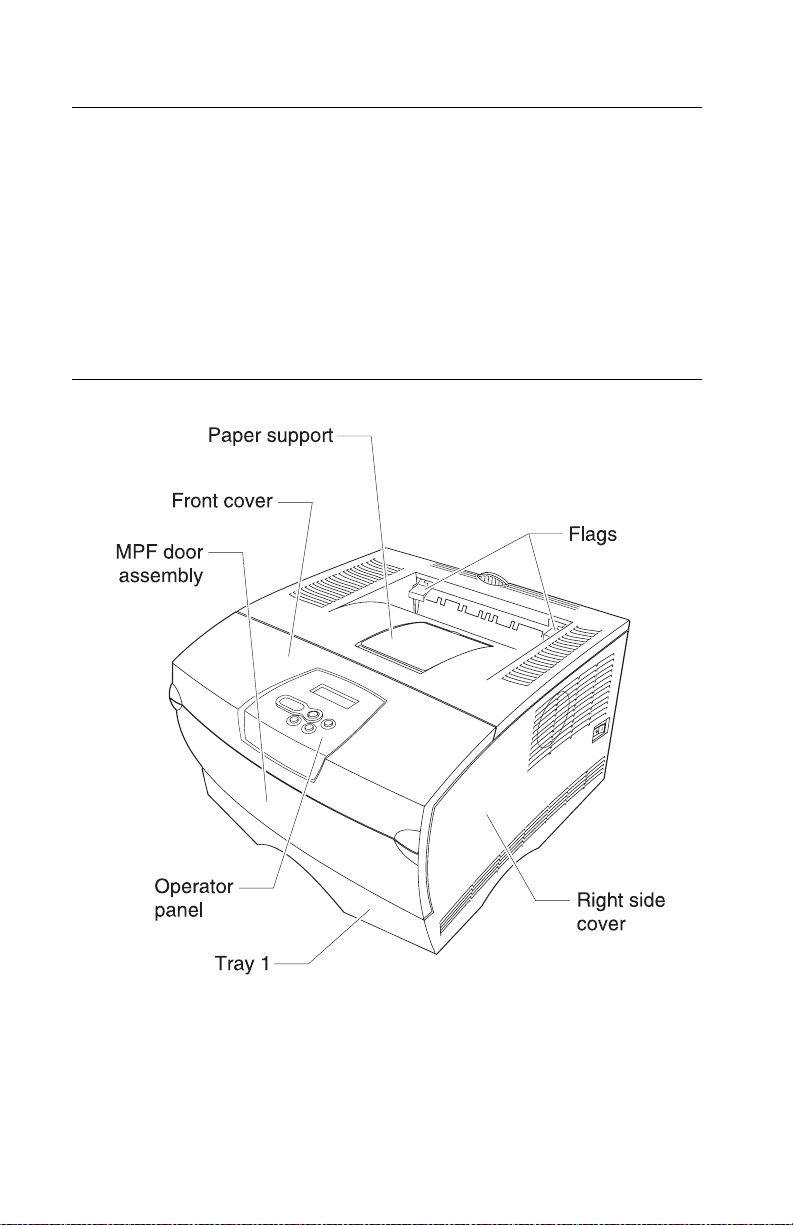
Exterior locations . . . . . . . . . . . . . . . . . . . . . . . . . . . . . . . . . . . . . . . . . . .5-1
Connectors . . . . . . . . . . . . . . . . . . . . . . . . . . . . . . . . . . . . . . . . . . . . . . . .5-2
Controller card assembly. . . . . . . . . . . . . . . . . . . . . . . . . . . . . . . . . . .5-2
Low voltage power supply (LVPS) . . . . . . . . . . . . . . . . . . . . . . . . . . .5-7
High voltage power supply (HVPS) . . . . . . . . . . . . . . . . . . . . . . . . . .5-8
Preventive maintenance . . . . . . . . . . . . . . . . . . . . . . . . . . . . . . . . . . . . . . .6-1
Safety inspection guide . . . . . . . . . . . . . . . . . . . . . . . . . . . . . . . . . . . . . .6-1
Lubrication specifications . . . . . . . . . . . . . . . . . . . . . . . . . . . . . . . . . . . . .6-1
Scheduled maintenance . . . . . . . . . . . . . . . . . . . . . . . . . . . . . . . . . . . . . .6-2
Maintenance kits . . . . . . . . . . . . . . . . . . . . . . . . . . . . . . . . . . . . . . . . .6-2
Maintenance kit parts group . . . . . . . . . . . . . . . . . . . . . . . . . . . . . . . .6-3
Parts catalog . . . . . . . . . . . . . . . . . . . . . . . . . . . . . . . . . . . . . . . . . . . . . . . . .7-1
How to use this parts catalog . . . . . . . . . . . . . . . . . . . . . . . . . . . . . . . . . .7-1
Assembly 1: Covers . . . . . . . . . . . . . . . . . . . . . . . . . . . . . . . . . . . . . . . . .7-2
Assembly 2: Paper feed . . . . . . . . . . . . . . . . . . . . . . . . . . . . . . . . . . . . . .7-4
Asse m b l y 3: Fram e . . . . . . . . . . . . . . . . . . . . . . . . . . . . . . . . . . . . . . . . . .7-6
Assembly 4: Multipurpose feeder (MPF). . . . . . . . . . . . . . . . . . . . . . . . . .7-8
Assembly 5: Fuser. . . . . . . . . . . . . . . . . . . . . . . . . . . . . . . . . . . . . . . . . . .7-9
Assembly 6: Charging . . . . . . . . . . . . . . . . . . . . . . . . . . . . . . . . . . . . . .7-10
Assembly 7: Electronics and cables 1 . . . . . . . . . . . . . . . . . . . . . . . . . .7-12
Assembly 8: Electronics and cables 2 . . . . . . . . . . . . . . . . . . . . . . . . . .7-14
Asse m b l y 9: Sens ors . . . . . . . . . . . . . . . . . . . . . . . . . . . . . . . . . . . . . . .7-18
Asse m b l y 10 : Opti on s . . . . . . . . . . . . . . . . . . . . . . . . . . . . . . . . . . . . . .7-20
Index . . . . . . . . . . . . . . . . . . . . . . . . . . . . . . . . . . . . . . . . . . . . . . . . . . . . . . . I-1
Part number index . . . . . . . . . . . . . . . . . . . . . . . . . . . . . . . . . . . . . . . . . . . . I-7
vi Service Manual
Page 7
4048-1xx
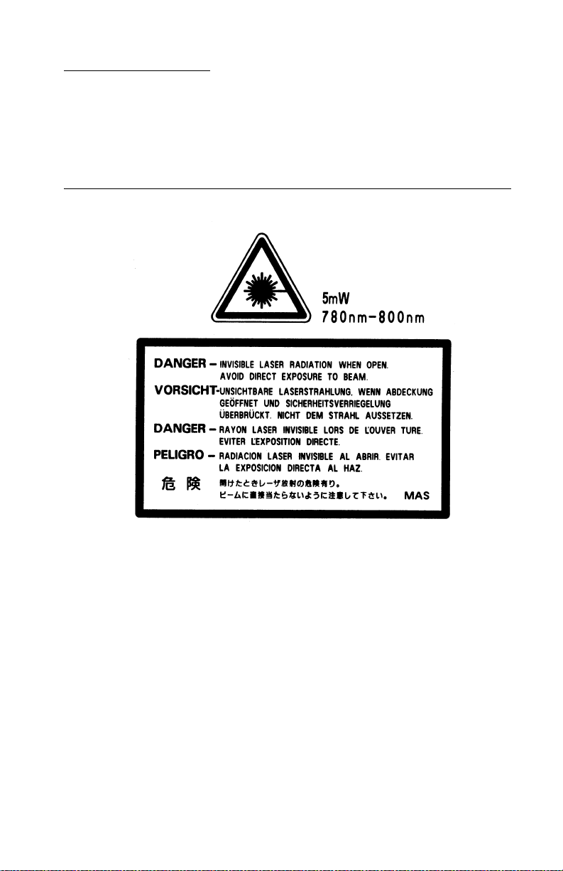
Laser notices
The following laser notice labels may be affixed to this printer as
shown:
Laser advis o ry label
Laser notices vii
Page 8

4048-1xx
Laser no tice
The printer is certified in the U.S. to conform to the requirements of
DHHS 21 CFR Subchapter J for Class I (1) laser products, and
elsewhere is certified as a Class I laser product conforming to the
requirements of IEC 60825-1.
Class I laser products are not considered to be hazardous. The
printer contains internally a Class IIIb (3b) laser that is nominally a 5
milliwatt gallium arsenide laser operating in the wavelength region of
770-795 nanometers. The laser system and printer are designed so
there is never any human access to laser radiation above a Class I
level during normal operation, user maintenance, or prescribed
service condition.
Laser
Der Drucker erfüllt gemäß amtlicher Bestätigung der USA die
Anforderungen der Bestimmung DHHS (Department of Health and
Human Services) 21 CFR Teil J für Laserprodukte der Klasse I (1).
In anderen Ländern gilt der Drucker als Laserprodukt der Klasse I,
der die Anforderungen der IEC (International Electrotechnical
Commission) 60825-1 gemäß amtlicher Bestätigung erfüllt.
Laserprodukte der Klasse I gelten als unschädlich. Im Inneren des
Druckers befindet sich ein Laser der Klasse IIIb (3b), bei dem es
sich um einen Galliumarsenlaser mit 5 Milliwatt handelt, der Wellen
der Länge 770-795 Nanometer ausstrahlt. Das Lasersystem und der
Drucker sind so konzipiert, daß im Normalbetrieb, bei der Wartung
durch den Benutzer oder bei ordnungsgemäßer Wartung durch den
Kundendienst Laserbestrahlung, die die Klasse I übersteigen würde,
Menschen keinesfalls erreicht.
viii Service Manual
Page 9

4048-1xx
Avis relatif à l’utilisation de laser
Pour les Etats-Unis : cette impr imant e est certifiée conforme aux
provisions DHHS 21 CFR alinéa J concernant les produits laser de
Classe I (1). Pour les autres pays : cette imprimante répond aux
normes IEC 60825-1 relatives aux produits laser de Classe I.
Les produits laser de Classe I sont considérés comme des produits
non dangereux. Cette imprimante est équipée d’un laser de Classe
IIIb (3b) (arséniure de gallium d’une puissance nominale de 5
milliwatts) émettant sur des longueurs d’onde comprises entre 770
et 795 nanomètres. L’imprimante et son système laser sont conçus
pour impossible, dans des conditions normales d’utilisation,
d’entretien par l’utilisateur ou de révision, l’exposition à des
rayonnements laser supérieurs à des rayonnements de Classe I .
Avvertenze sui prodotti laser
Questa stampante è certificata negli Stati Uniti per essere conforme
ai requisiti del DHHS 21 CFR Sottocapitolo J per i prodotti laser di
classe 1 ed è certificata negli altri Paesi come prodotto laser di
classe 1 conforme ai requisiti della norma CEI 60825-1.
I prodotti laser di classe non sono considerati pericolosi. La
stampante contiene al suo interno un laser di classe IIIb (3b)
all’arseniuro di gallio della potenza di 5mW che opera sulla
lunghezza d’onda compresa tra 770 e 795 nanometr i. Il sistema
laser e la stampante sono stati progettati in modo tale che le
persone a contatto con la stampante, durante il normale
funzionamento, le operazioni di servizio o quelle di assistenza
tecnica, non ricevano radiazioni laser superiori al livello della
classe 1.
Laser notices ix
Page 10

4048-1xx
Avisos sobre el láser
Se certifica que, en los EE.UU., esta impresora cumple los
requisitos para los productos láser de Clase I (1) establecidos en el
subcapítulo J de la norma CFR 21 del DHHS (Departamento de
Sanidad y Servicios) y, en los demás países, reúne todas las
condiciones expuestas en la norma IEC 60825-1 para productos
láser de Clase I (1).
Los productos láser de Clase I no se consideran peligrosos. La
impresora contiene en su interior un láser de Clase IIIb (3b) de
arseniuro de galio de funcionamiento nominal a 5 milivatios en una
longitud de onda de 770 a 795 nanómetros. El sistema láser y la
impresora están diseñados de forma que ninguna persona pueda
verse afectada por ningún tipo de radiación láser superior al nivel de
la Clase I durante su uso normal, el mantenimiento realizado por el
usuario o cualquier otra situación de servicio técnico.
Declaração sobre Laser
A impressora está certificada nos E.U.A. em conformidade com os
requisitos da regulamentação DHHS 21 CFR Subcapítulo J para a
Classe I (1) de produtos laser. Em outros locais, está certificada
como um produto laser da Classe I, em conformidade com os
requisitos da norma IEC 60825-1.
Os produtos laser da Classe I não são considerados perigosos.
Internamente, a impressora contém um produto laser da Classe IIIb
(3b), designado laser de arseneto de potássio, de 5 milliwatts
,operando numa faixa de comprimento de onda entre 770 e 795
nanómetros. O sistema e a impressora laser foram concebidos de
forma a nunca existir qualquer possiblidade de acesso humano a
radiação laser superior a um nível de Classe I durante a operação
normal, a manutenção feita pelo utilizador ou condições de
assistência pres critas.
x Service Manual
Page 11

4048-1xx
Laserinformatie
De printer voldoet aan de eisen die gesteld worden aan een
laserprodukt van klasse I. Voor de Verenigde Staten zijn deze eisen
vastgelegd in DHHS 21 CFR Subchapter J, voor andere landen in
IEC 60825-1.
Laserprodukt en van klasse I worden niet als ongevaarlijk
aangemerkt. De printer is voorzien van een laser van klasse IIIb
(3b), dat wil zeggen een gallium arsenide-laser van 5 milliwatt m e t
een golflengte van 770-795 nanometer. Het lasergedeelte en de
printer zijn zo ontworpen dat bij normaal gebrui k, bij onderhoud of
reparatie conform de voorschriften , nooit blootste lling mogelijk is
aan laserstraling boven een niveau zoals voorgeschrev en is voor
klasse 1.
Lasermeddelelse
Printeren er godkendt som et Klasse I-laserprodukt, i
overenstemmelse med kravene i IEC 60825-1.
Klasse I-laserprodukter betragtes ikke som farlige. Printeren
indeholder internt en Klasse IIIB (3b)-laser , der nominelt er en 5
milliwatt galliumarsenid laser, som arbejder på bølgelængdeområdet
770-795 nanometer. Lasersystemet og printeren er udformet
således, at mennesker aldrig udsættes for en laserstråling over
Klasse I-niveau ved normal drift, brugervedligeholdelse eller
obligatoriske servicebetingelse r.
Laser notices xi
Page 12

4048-1xx
Huomautu s las er laitteesta
Tämä kirjoitin on Yhdysvalloissa luokan I (1) laserlaitteiden DHHS
21 CFR Subchapter J -määrityksen mukainen ja muualla luokan I
laserlaitteiden IEC 60825-1 -määrityksen mukainen.
Luokan I laserlaitteiden ei katsota olevan vaarallisia käyttäjälle.
Kirjoittimessa on sisäinen luokan IIIb (3b) 5 milliwatin
galliumarsenidilaser, joka toimii aaltoalueella 770 - 795 nanometriä.
Laserjärjestelmä ja kirjoitin on suunniteltu siten, että käyttäjä ei
altistu luokan I määrityksiä voimakkaammalle säteilylle kirjoittimen
normaalin toiminnan, käyttäjän tekemien huoltotoimien tai muiden
huoltotoimien yhteydessä.
VARO! Avattaessa ja suojalukitus ohitettaessa olet alttiina
näkymättömälle lasersäteilylle. Älä katso säteeseen.
VARNING! Osynlig laserstrålning när denna del är öppnad och
spärren är urkopplad. Betrakta ej strålen.
Laser-notis
Denna skrivare är i USA certifierad att motsvara kraven i DHHS 21
CFR, underparagraf J för laserprodukter av Klass I (1). I andra
länder uppfyller skrivaren kraven för laserprodukter av Klass I enligt
kraven i IEC 60825-1.
Laserprodukter i Klass I anses ej hälsovådliga. Skrivaren har en
inbyggd laser av Klass IIIb (3b) som består av en laserenhet av
gallium-arsenid på 5 milliwatt som arbetar i våglängdsområdet 770795 nanometer. Lasersyst emet och skrivaren är utfo rmade så att det
aldrig finns risk för att någon person utsätts för laserstrålning över
Klass I-nivå vid normal användning, underhåll som utförs av
användaren eller annan föreskriven serviceåtgärd.
xii Service Manual
Page 13

4048-1xx
Laser-melding
Skriveren er godkjent i USA etter kravene i DHHS 21 CFR,
underkapittel J, for klasse I (1) laserprodukter, og er i andre land
godkjent som et Klasse I-laserproduk t i samsvar med kravene i IEC
60825-1.
Klasse I-laserprodukter er ikke å betrakte som farlige. Skriveren
inneholder internt en klasse IIIb (3b)-laser, som består av en
gallium-arsenlaserenhet som avgir stråling i bølgelengdeområdet
770-795 nanometer. Lasersystemet og skriveren er utformet slik at
personer aldri utsettes for laserstråling ut over klasse I-nivå under
vanlig bruk, vedlikehold som utføres av brukeren, eller foreskrevne
serviceopera sjoner.
Avís sobre el Làser
Segons ha estat certificat als Estats Units, aquesta impressora
compleix els requisits de DHHS 21 CFR, apartat J, pels productes
làser de classe I (1), i segons ha estat certificat en altres llocs, és un
producte làser de classe I que compleix els requisits d’IEC 60825-1.
Els productes làser de classe I no es consideren perillosos. Aquesta
impressora conté un làser de classe IIIb (3b) d’arseniür de gal.li,
nominalment de 5 mil.liwats, i funciona a la regió de longitud d’ona
de 770-795 nanòmetres. El sistema làser i la impressora han sigut
concebuts de manera que mai hi hagi exposició a la radiació làser
per sobre d’un nivell de classe I durant una operació normal, durant
les tasques de manteniment d’usuar i ni durant els serveis que
satisfacin les condicions prescrites.
Laser notices xiii
Page 14
4048-1xx
Japanese Laser Notice
Chinese Laser Notice
xiv Service Manual
Page 15
4048-1xx
Korean Laser Notice
Laser notices xv
Page 16

4048-1xx
xvi Service Manual
Page 17

4048-1xx
Safety information
• The safety of this product is based on testing and approvals of
the original design and specific components. The manufacturer
is not responsible for safety in the event of use of unauthorized
replacement par ts.
• The maintenance information for this product has been
prepared for use by a professional service person and is not
intended to be used by others.
• There may be an increased risk of electric shock and personal
injury during disassembly and servicing of this product.
Professional service personnel should understand this and take
necessary precaut ions.
• CAUTION: When you see this symbol, there is a
danger from hazardous voltage in the area of the
product where you are working. Unplug the product
before you begin, or use caution if the product must
receive power in order to perform the task.
Consig n es de sécu ri té
• La sécurité de ce produit repose sur des tests et des
agréations portant sur sa conception d'orig ine et sur des
composants particuliers. Le fabricant n'assume aucune
responsabilité concernant la sécurité en cas d'utilisation de
pièces de rechange non agréées.
• Les consignes d'entretien et de réparation de ce produit
s'adressent uniquement à un personnel de maintenance
qualifié.
• Le démontage et l'entretien de ce produit pouvant présenter
certains r isques électr iqu es, le personnel d'entretien qualifié
devra prendre toutes les précautions nécessaires.
• ATTENTION : Ce symbole indique la présence
d'une tension dang ereus e dans la par t ie du produit
sur laquelle vous travaillez. Débranchez le produit
avant de commencer ou faites preuve de vigilance si
l'exécution de la tâche exige que le produit reste sous
tension.
Safety information xvii
Page 18

4048-10x
Norme di sicurezza
• La sicurezza del prodotto si basa sui test e sull'approvazione
del progetto originale e dei componenti specifici. Il produttore
non è responsabile per la sicurezza in caso di sostituzione non
autorizzata delle parti.
• Le informazioni riguardanti la manutenzione di questo prodotto
sono indirizzate soltanto al personale di assistenza autorizzato.
• Durante lo smontaggio e la manutenzione di questo prodotto,
il rischio di subire scosse elettriche e danni alla persona è più
elevato. Il personale di assistenza autorizzato deve, quindi,
adottare le precauzioni necessarie.
• ATTENZIONE: Questo simbolo indica la presenza
di tensione pericolosa nell'area del prodotto.
Scollegare il prodotto prima di iniziare o usare
cautela se il prodotto deve essere alimentato per
eseguire l'intervento.
Sicherheitshinweise
• Die Sicherheit dieses Produkts basiert auf T ests und
Zulassungen des ursprünglichen Modell s und bestimmter
Bauteile. Bei Verwendung nicht genehmigter Ersatzteile wird
vom Hersteller keine Verantwortung oder Haftung für die
Sicherheit übernommen.
• Die Wartungsinformationen für dieses Produkt sind
ausschließlich für die Verwendung durch einen
Wartungsfachmann bestimmt.
• Während des Auseinandernehme ns und der Wartung des
Geräts besteht ein zusätzliches Risiko eines elektrischen
Schlags und körperlicher Verletzung. Das zuständige
Fachpersonal sollte entsprechende Vorsichtsmaßnahmen
treffen.
• ACHTUNG: Dieses Symbol weist auf eine
gefährliche elektrische Spannung hin, die in diesem
Bereich des Produkts auftreten kann. Ziehen Sie vor
den Arbeiten am Gerät den Netzstecker des Geräts,
bzw. arbeiten Sie mit großer Vorsicht, wenn das
Produkt für die Ausführung der Arbeiten an den
Strom angeschlossen sein muß.
xviii Service Manual
Page 19

4048-1xx
Pautas de Seguridad
• La seguridad de este producto se basa en pruebas y
aprobaciones del diseño original y componentes espec íficos.
El fabricante no es responsable de la seguridad en caso de uso
de piezas de repuesto no autorizadas.
• La información sobre el mantenimiento de este producto está
dirigida exclusivamente al personal cualificado de
mantenimiento.
• Existe mayor riesgo de descarga eléctrica y de daños
personales durante el desmontaje y la reparación de la
máquina. El personal cualificado debe ser consciente de este
peligro y tomar las precauciones necesarias.
• PRECAUCIÓN: este símbolo indica que el voltaje
de la parte del equipo con la que está trabajando es
peligroso. Antes de empezar, desenchufe el equipo
o tenga cuidado si, para trabajar con él, debe
conectarlo.
Informações de Segurança
• A segurança deste produto baseia-se em testes e aprovações
do modelo original e de componentes específicos. O fabricante
não é responsável pela segunrança, no caso de uso de peças
de substituição não autorizadas.
• As informações de segurança relativas a este produto
destinam-se a profissionais destes serviços e não devem ser
utilizadas por outras pessoas.
• Risco de choques eléctricos e ferimentos graves durante a
desmontagem e manutenção deste produto. Os profissionais
destes serviços devem estar avisados deste facto e tomar os
cuidados necessários.
• CUIDADO: Quando vir este símbolo, existe a
possível presença de uma potencial tensão perigosa
na zona do produto em que está a trabalhar. Antes
de começar, desligue o produto da tomada eléctrica
ou seja cuidadoso caso o produto tenha de estar
ligado à corrente eléctrica para realizar a tarefa
necessária.
Safety information xix
Page 20
4048-10x
Inf ormació de Seguretat
• La seguretat d'aquest producte es basa en l'avaluació i
aprovació del disseny original i els components específics.
El fabricant no es fa responsable de les qüestions de
seguretat si s'utilitzen peces de recanvi no autoritzades.
• La informació pel manteniment d’aquest producte està
orientada exclusivament a professionals i no està destinada
a ningú que no ho sigui.
• El risc de xoc elèctric i de danys personals pot augmentar
durant el procés de desmuntatge i de servei d’aquest producte.
El personal professional ha d’estar-ne assabentat i prendre
les mesures convenie n ts.
• PRECAUCIÓ: aquest símbol indica que el voltatge
de la part de l'equip amb la qual esteu treballant és
perillós. Abans de començar, desendolleu l'equip
o extremeu les precaucions si, per treballar amb
l'equip, l'heu de connectar.
xx Service Manual
Page 21
4048-1xx
Safety information xxi
Page 22

4048-10x
Preface
This manual contains maintenance procedures for service
personnel. It is divided into the following chapters:
1. General informati on contains a general description of the
printer and the maintenance approach used to repair it. Special
tools and test equipment are listed, as well as general
environmental and safety instructions.
2. D iagnostic information contains an error indicator table,
symptom tables, and service checks used to isolate failing field
replaceable units (FRUs).
3. D iagnostic aids contains tests and checks used to locate or
repeat symptoms of printer problems.
4. Repair information provides instructions for making printer
adjustments and removing and installing FRUs.
5. Locations and connections uses illustrations to identify the
connector locations and test points on the printer.
6. Preventive maintenance contains the lubrication specifications
and recommendations to prevent problems.
7. Parts catalog contains illustrations and part numbers for
individual FRUs.
Definitions
Note: A note provides additional information.
Warning: A warning identifies something that might damage the
product hardware or software.
CAUTION: A caution identifies something that might cause a
service r harm.
CAUTION: When you see this symbol, there is a
danger from hazardous voltage in the area of the
product where you are working. Unplug the product
before you begin, or use caution if the product must
receive power in order to perform the task.
xxii Service Manual
Page 23

4048-1xx
1. Gen e r a l informa tion
The Lexmark™ T430 (4048-1xx) laser printer is a monochrome
laser printer designed for individual users or small workgroups.
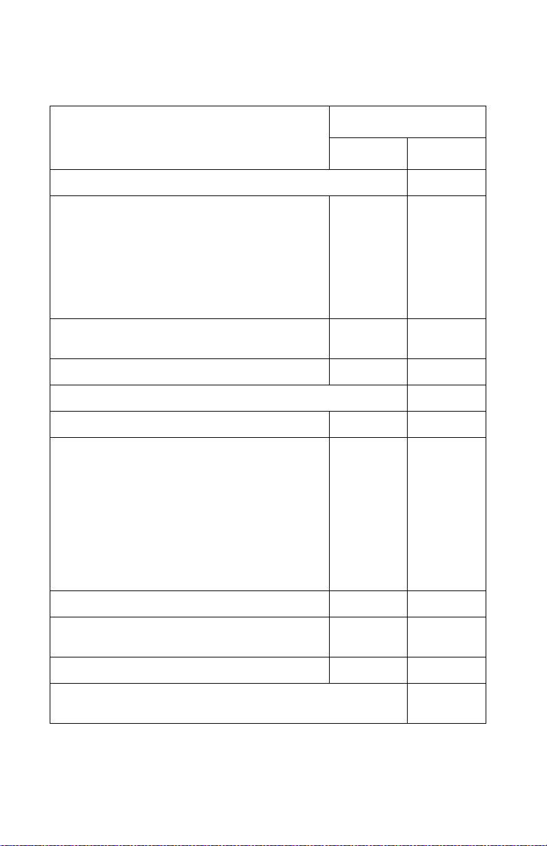
Models
There are three models, differing on standard features, including
standard memor y. For information on standard and optional
memory, see “Memory and user flash memory” on page 1-5.
Models
Standard features
Duplex ✓✓✗
Parallel interface connector
(1284–B connector.)
Parallel mod e 2 ✓✓✓
USB port ✓✓✓
Ethernet adapter, integrated ✗✓✗
✓ Indicates attachment is part of the factory ship ped configuration.
✗ Indicates att a chment is not part of the factory shi pped configuration.
101 102 111
✓✓✓
Maint en an ce ap proa ch
The diagnostic information leads you to the correct field replaceable
unit (FRU) or part. Use the error code charts, symptom index, and
service checks to determine the symptom and repair the failure. See
“Diagn ost ic in formation” on page 2-1, for the location of each
section. See the “Re pair i nformation” on page 4-1 to help identify
parts. After completing the repair, perform tests as needed to verify
the repair.
General information 1-1
Page 24
4048-1xx
Special tools
Long Phillips screwdr iver (appr oximately 6–inc h shank )
Slotted screwdriver
Small Phillips screwdriver
Spring hook
When taking voltage readings, always use the printer frame as
ground unless another ground is specified.
Printer identification
Serial number
Look for the serial number label on the inside front cover of the
printer.
1-2 Service Manual
Page 25
4048-1xx
Printer features and specifications
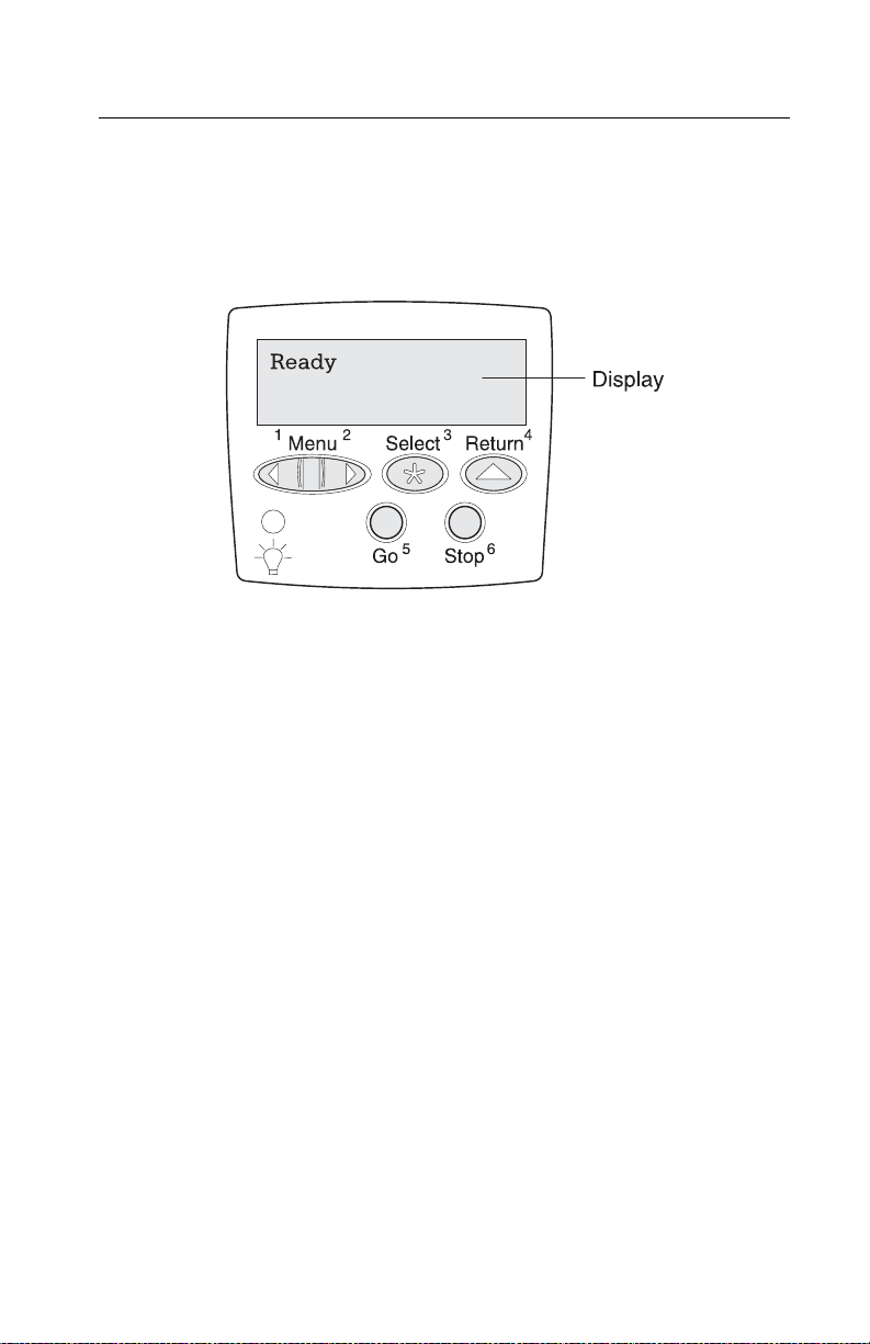
Operator panel
The operator panel consists of a two-line display and six buttons
(Menu is two buttons).
General information 1-3
Page 26

4048-1xx
Resolution and print quality
• IET, PictureGrade™, print resolution, print darkness, and toner
saver can all be set independently of each other through the
data stream.
• Control panel menus let a user independently set PictureGrade
and print resolution.
• The IET setting is selected when a print resolution is selected
using the Quality Menu.
• Toner saver and print darkness settings are set when a toner
darkness is selected using the Quality Menu.
Print Quality setti ng All models
Print resoluti o n :
• 300 dpi
• 600 dpi
• 1200 Image Quality
• 2400 Image Quality
• 1200 dpi
Image Enhancement Technology
(IET):
• 2 bits/pel
• 4 bits/pel
✓
✓
✓
✓
✓
✓
✓
Toner sa ver ✓
Print darkness ✓
PictureGrade ✓
Indicates print quality setting is supported.
✓
1-4 Service Manual
Page 27

4048-1xx
Memory and user flash memory
Each model has a standard amount of memory (RAM) soldered on the
controller card, and a certain number of 100-pin DIMM slots available for
installing addi tional memory or user flash memory options.
Models
Memory
Standard memory 32MB 64MB
Standard flash memory None None
Memory options
8MB DIMM
16MB DIMM
32MB DIMM
64MB DIMM
128MB DIMM
256MB DIMM
Maximum # of memory DIMM 1 1
Maximum possible memory 288MB 320MB
Flash memory options
16MB
32MB
Maximum # of flash memory options 1 1
Maximum possible flash memory 32MB 32MB
✓ Indicates opt ion is supported.
101 and 111 102
✓
✓
✓
✓
✓
✓
✓
✓
✓
✓
✓
✓
✓
✓
✓
✓
Printer data streams
Data streams All mode ls
PCL 6 emulation ✓
Post Scri pt 3 emulation ✓
PPDS ✓
PDF (version 1.3) ✓
General information 1-5
Page 28

4048-1xx
Print area
The following print area settings are available.
Print a re a o p tion All mode ls
Normal ✓
Fit to page ✗
Edge to edge ✓
Supplies
Print cartridge Average yield
Lexmark Return Progr am
print cartridges
Regular cartridges (without Lexmark
Return Program terms and
conditions)
6,000
12,000
6,000
12,000
Approximate
coverage
Fonts
Fonts/options All models
PCL bitmapped 2
PCL scalable 89
PostScript scalable 91
PPDS bitmapped 5
PPDS scalable 39
Note: Additional fonts can be downloaded to the printer RAM, or
optional user flash.
5%
5%
5%
5%
1-6 Service Manual
Page 29

4048-1xx
Media and pape r ha nd l in g
Media
The following table shows the supported media, media weights and
media textures which together provide optimal print quality across a
variety of media.
Media supported All models
Paper ✓
Card stock ✓
Transparency ✓
Labels ✓
Envelope ✓
Bond ✓
Media weights
Heavy ✓
Normal ✓
Light ✓
Media text ures
Rough ✓
Normal ✓
Smooth ✓
Note:
✓ Indicates media is suppor ted.
General information 1-7
Page 30
4048-1xx
Standard and optional paper sources
Models
Media sources
Standard
Standard input sources: 2 2
• Integrated 250–sheet tray
The 250-sheet drawer supports the fo ll owing
sizes: A4, A5, JIS B5, folio, letter, legal,
ex ecutive, and statement.
• Multipurpose feeder 1 1
Standard output destination (150-s heet sensing
bin)
Duplex (standard in models 101 and 102, only) ✓✗
Options
Maximum # of optional drawers 2 2
Optional drawers:
Note: When two optional dra w ers are installed ,
the first must be a 250-sheet draw er.
• 250–sheet drawer ✓✓
• 500–sheet drawer
The 500 sheet drawer supports the following
sizes: A4, JIS B5, folio, letter , legal, and
executive.
101, 102 111
11
11
✓✓
Maximum number of media input sources 4 4
Maximum input sheet capacity (excluding
envelopes)
Maximum sheet capacity (excluding envelopes) 150 150
✓ Indicates associated capability is supported.
Assumes 20 lb xerographic pap er.
1000 1000
1-8 Service Manual
Page 31

4048-1xx
Input media sources
Supported input sizes
Letter ✓✓✓✓✓
11 x 17
Legal ✓✓✓✓✓
A4 ✓✓✓✓✓
A3
A5 ✓✓✓
Folio ✓✓✓✓✓
Statement ✓✓✓
JIS-B4
JIS-B5 ✓✓✓✓✓
Executive ✓✓✓✓✓
Universal ✓✓✓✓✓
*
Integrated
feeder
Multipurpose
250-sheet tray
Optional
Optional
250- sheet drawer
Duplex
500- sheet drawer
(models 101, 102 only)
7 3/4 envelope ✓
9 envelope ✓
10 envelope ✓
DL envelope ✓
C5 envelope ✓
B5 envelope ✓
Other envelope ✓
✓ Size supported without size sensing.
General information 1-9
Page 32

4048-1xx
Output media
Supported output sizes
Letter ✓✓
A4 ✓✓
Legal ✓ *
11 x 17
A3
Folio ✓✓
Statement ✓✓
A5 ✓✓
JIS-B4
JIS-B5 ✓✓
Executive ✓✓
Universal ✓ *
7 3/4 envelope ✓✓
9 enve lope ✓✓
150-sheet
standard bin
20-sheet
rear exit
10 envelope ✓✓
DL envelope ✓✓
C5 envelope ✓✓
B5 enve lope ✓✓
Other envelope ✓✓
* Size supported, but results may be unacceptable.
1-10 Service Manual
Page 33

4048-1xx
Acronyms
ASIC Application-Specific Integrated Circuit
C Charge Roll
CRC Cyclic Redundancy Check
DC Direct Current
DEV Developer Rol l
DIMM Dual In-line Memory Module
DRAM Dynamic Random Access Memory
ECC Error Checking and Correction
EPROM Erasabl e Programabl e Read-Only Memory
FRU Field Replaceable Unit
GND Ground
HVPS High Voltage Power Supply
IET Image Enhancement Technology
KB Kilobyte
LCD Liquid Crystal Display
LSU Laser Scanning Unit
LVPS Low Voltage Power Supply
MPF Multipurpose Feeder
NAND Not And (Gate)
NVRAM Nonvolatile Rando m Acce ss M em ory
PIN Personal Identification Number
PJL Printer Job Language
POR Power–On Reset
POST Power–On Self Test
PPDS Personal Printer Data Stream
RAM Random Access Memory
RIP Raster Image Processo r
SDRAM Synchronous Dynamic Random Access Memory
SRAM Sta ti c Random Access Memory
T Transfer (Roll )
TAR Toner Adde r Rol l
USB Universal Serial Bus
Vac Volts Alternating Current
General information 1-11
Page 34

4048-1xx
1-12 Service Manual
Page 35

4048-1xx
2. Diagnostic information
Start
CAUTION: Unplug power from the printer before
connecting or disconnecting any cable, assembly, or
electronic card. This is a precaution for personal safety
and to prevent damage to the printer.
This chapter contains the codes and diagnostic tools to aid in
providing corrective action for a malfunctioning printer. To determine
the corrective action to repair a printer, look for the following
information:
• Does the POR stop? Check the:
– “Power–On Reset (POR) sequence” on page 2-2
– “POST s ym ptom table” on page 2 -3.
• Do you have a symptom, rather than an error message? Check
the “Symptom tables” on page 2-3.
• If you have an error message or user message, check the
following:
– “Serv ice error codes ” on page 2-6
– “User attendance messages” on page 2-11.
• Additional information:
– “Service checks” on page 2-36
– “Solving print quality problems” on page 2-56.
Diagnostic information 2-1
Page 36

4048-1xx
Power–On Reset (POR) sequence
The following is an example of the events that occur during the POR
sequence when the printer is turned on.
1. Diamonds are displayed on the operator panel.
2. While code is being loaded into DRAM, dots scroll across the
operator panel.
3. A screen is displayed with the memory and processor speed. A
typical example of this message is:
*
32 Mb 366 Mhz
4. Performing Self Test is displayed.
5. Busy is displayed.
6. Close Door will be posted if the cover is open.
7. Any cartridge errors, such as Defective Cartridge are
posted.
8. Applicable maintenance messages are posted. For example, 80
Scheduled Maintenance.
9. Applicable toner low messages are posted.
10. T he pri nter displays Ready.
2-2 Service Manual
Page 37

4048-1xx
Symptom tables
POST symptom table
These symptoms may appear during the POST (Power-on Self
Test). See “Po wer–On Reset (POR) sequence” on page 2-2 for
the sequence when a printer is turned on.
Symptom Action
The main motor, cooling fan and
fuser do not come on.
POST complete s except displa y is
inco mplete or erratic.
POST complete e xcept display
does not function.
Main motor does not come on. See “M ai n moto r se rvice check”
Fan does not come on. See “Cooling fan service check”
Fuser heater does not com e on. See “ Cold fuser service ch eck” on
Fuser heater never turns off. See “Hot fuser service chec k” on
The paper feed picks and tries to
feed paper.
See “Cover inter lock switch
service check” on page 2-37.
See “Operator pane l service
check” on page 2-43.
See “Operator pane l service
check” on page 2-43.
on page 2-42.
on page 2-36.
page 2-41.
page 2-41.
See “Paper feed service checks”
on page 2-45.
Diagnostic information 2-3
Page 38

4048-1xx
Printer symptom table
Symptom Action
Dead machine (no power) See “Dead machine service
check” on page 2-39.
Fan noisy or not working See “Cooling fan service check”
Fuser parts melted See “Hot fuser service check” on
Fuser heater does not acti vate See “Cold fuser servic e check” on
Toner not fused to the paper See “Poor fusing of image” on
Blank page See “Blank page” on page 2-50.
Black page See “Black page” on page 2-51.
Heavy background See “Heavy background” on
Light print See “Light print” on page2-54.
White or blac k li nes or bands See “White or black lines or
Toner on back of page See “Toner on bac k of page” on
Paper jams See “Paper feed service checks”
Main motor noisy or does not
move
on page 2-36.
page 2-41.
page 2-41.
page 2-53.
page 2-52.
bands” on page 2-54.
page 2-55.
on page 2-45.
See “Main motor servi ce check”
on page 2-42.
Paper never picks See “Paper never picks” on
Paper feeds contin uously See “Paper picks during POST
Skewed paper See Note regarding align me nt on
page 2-48.
and/or continuous ly” on
page 2-46.
page 4-64 or “Pa per feed service
checks” on page 2-45.
2-4 Service Manual
Page 39

4048-1xx
Symptom Action
Printer not communicating with
host
Paper wrink led or bent See “Paper “trees,” wrinkles,
Top cover will not close See “Cover interlock switch
Operator panel button does not
respond
Operator pan el li ght does not light
or is very dim
See “Parallel port service chec k”
on page 2-49.
stacks poorly or curls” on
page 2-49.
service check” on page 2-37.
See “Operator pane l service
check” on page 2-43 or
“Controller card service check”
on page 2-38.
See “Controller card service
check” on page 2-38.
Diagnostic information 2-5
Page 40

4048-1xx
Messag es an d er ror code s
Service error codes
Service error codes are generally non-recoverabl e except in an
intermittent condition when you can POR the printer to temporarily
recover from the error condition.
Service error codes (9xx)
Error Description Action
900 RIP software Server firmware problem. Contact the
902 General engine
software failure
910 DC exit motor stall The load on the exit motor is too high or
911 DC exit motor
912 DC exit motor below
speed
913 DC exi t m otor over
speed
914 DC pick motor–no
encoder feedback
917 Transfer roll The most likely cause is a faulty HVPS. It
920 Fuser error Indicates that the fuser is below
next level of support.
An unrecoverable system software error.
Reset the printer (POR) . If the pr oblem
continues, replace the controller card.
there is a c abli ng prob l em. Fir st, c heck for
jams and then move the exit rol lers,
located between the rear door and fuser,
while observing the DC motor. If the
torque is too high, isolate the problem to
the redriv e and repair or replace as
necessary. If the torque seems normal,
check the cabling f or continuity and
replace the moto r with cabling.
Verify motor is plugged into controller
card correct ly. Also check load condition
(see service error 910, above).
may als o indi cate a problem in the
transfer roll area. Go to “Transfer roll
service check” on page 2-44.
temperature when printing. Go to “Fuser
service check” on page 2-40.
922 Fuser error Fuser fai led to reach standby
temperature. Verify line voltage to the
fuser. Go to “Fuser service check” on
page 2-40.
2-6 Service Manual
Page 41

4048-1xx
Service error codes (9xx) (continued)
Error Description Action
923 Fuser error Fuser is too hot during printing or when
924 Fuser error An open circuit has been detected in the
929 Toner sensor The toner sensor is not operating
931 Printhead—no first
hysnc
932 Printhead—lost hsyncs Replace the printhead.
934 Mirror motor lost lock Replace the printhead.
935 Mirror motor unable to
reach operati ng speed.
936 Transport motor initial
lock failure
937 Transport motor lost
lock
printer is idle. Go to “Fuser service
check” on page 2-40.
fuser thermistor circuit. Check cabling
and connectors. Go to “Fuser service
check” on page 2-40.
properly, the developer driv e assem bly is
not operating properly, or the print
cartridge is defective. Go to “Sensor
Tes t” on page 3-12.
Check for unplugged printhead, faulty
cabling, or faulty printhe ad.
Faulty printhead, cabl ing or connector.
Indicates a problem with the main drive
motor or a jam occurr ed during the motor
ramp-up to speed.
Faulty motor or a jam occurred after
motor ramp-up to speed. Possible
problem with the main drive.
939 RIP—engine
communications
The RIP processor cannot communicate
with the engine processor. Replace the
controller card. Go to “Controller card
assembly r em oval” on page 4-50. If the
problem persists, contact the next level of
support.
Diagnostic information 2-7
Page 42

4048-1xx
Service error codes (9xx) (continued)
Error Description Action
940 LV Po wer Supply The low voltage pow er supply zero
941 Controller card This error indicates an op en fuse in line to
950 Controller card There is a mismatch between the
crossover test failed.
Check the LVPS for correct installation.
Make sure the connector on the LVPS
assembl y is firmly seated with the
connector on the interconnect card
connector.
This error may also be caused by a noisy
AC input power source.
• Be sure the correct LVPS has been
installed.
• If all the above are correct, replace the
LVPS assembly.
tray 2. POR the pr i n te r to re se t the fuse.
Check for +24 V dc on J21, pin 6. If
correct, the fuse is okay. If incorrect,
remov e the drawer and check resistance
between pin 6 and 5 of the tray. If the
resistance is less than 50 ohms, re place
the drawer.
variables in the EPROM on the operator
panel card and those in the secure
NVRAM on the controller car d. This can
only occur aft er a replacement of one of
the two parts and the replaced part is
faulty. Replace the controller card or the
operator panel.
Warning: Always replace only one at a
time with a POR between.
951 Controller card The secure NVRAM was not detected on
952 NV failure:n Recoverable error. Reset (POR) the
953 NVRAM chip failure Indicates the NVRAM chip has failed.
954 NVRAM CRC failure Indicates the NVRAM experienced a CRC
the controller card. Replace the c ontroller
card.
printer.
Replace the controller card.
failure. Replace the controller card.
2-8 Service Manual
Page 43

4048-1xx
Service error codes (9xx) (continued)
Error Description Action
955 Code CRC <loc> Replace the controller card. Where
956 Controller card Error codes 956, 957, and 959 are
957 ASIC fai lure Error codes 956, 957, and 959 are
958 NAND fail ure Before proceeding, perform a power on
959 SRAM failure Error codes 956 , 957, and 959 are
960 RAM soldered on the
card is bad
<loc> = CRC Failure or ECC Failure on
the controller card.
controller card failures.
Perform a power on reset (POR). If th is
does not fix the problem, replace the
controller card.
controller card failures.
Perform a power on reset (POR). If th is
does not fix the problem, replace the
controller card.
reset (POR) to see if the ECC error
correction code can reflash NAND .
If this does not fix the problem, replace
the controller card.
controller card failures.
Perform a power on reset (POR). If th is
does not fix the problem, replace the
controller card.
Indicates a DRAM Memory Error on the
controller card. Replace the contro ll er
card.
961 RAM in slot 1 is bad If another SDRAM memory DIMM is
available, turn the power off and switch
the DIMM. If the memory card now works
correctly, replace the failing DIMM . I f thi s
does not fix the problem, replace the
controller card. If another DIMM is not
available, replace the memory option first
and then the controller card if necessary.
Diagnostic information 2-9
Page 44

4048-1xx
Service error codes (9xx) (continued)
Error Description Action
964 Download emulation
CRC failure. Chec ksum
failure detected in the
emulation header or
emulation file.
975 Unrecognizable
network port
976 Software error in
network port
978 Bad checksum while
programming network
port.
979 Flash parts failed while
programming network
port.
980 <dev ice> Co mm
The engine is
experienci ng unreliab le
communications to the
specified device.
Pe rform the following:
1. Disable the downloaded emulations.
See “Download Emuls” on
page 3-24.
2. Reprogram the downloaded
emulations.
If the prob lem persists, repl ace the
emulation card.
A failure with the network port.
If the printer is a network model, replace
the control ler card. See “Cont roller card
assembl y rem oval” on page 4-50.
Service errors 980 t hrough 9 84, <device>
can be one of the fo ll owing: Engine ,
Duplex, or Tray x (x=1, 2, or 3).
2-10 Service Manual
Page 45

4048-1xx
User attendance messages
User attendance messages
Message Explanation
Change Cartridge
Invalid Refill
Change <input source>
<custom type name>
Change <input source>
<custom string>
Change <input source>
<size>
Remove the print cartridge and install a new
cartridge.
This message displays when the user should
change the media installed in one of the input
options.
•<input source>=Tray 1 , Tray 2, Tray 3, or M P
feeder.
•<Custom Type name>=Custom 1 through
Custom 6 using the MarkVision™ utility.
When the printer is prompti ng for one of the
custom types which has been named by the
user , then only the custom type name i s
displayed on line 2. The name ma y be
truncat e d to fit the display.
This message displays when the user should
change the media installed in one of the input
options.
•<input source>=Tray 1, Tray 2,Tray 3 , o r M P
feeder.
•<custo m string>= a user definable name.
This message displays when the user should
change the media installed in one of the input
options:
•<input source>=Tray 1 , Tray 2, Tray 3, or M P
feeder.
•<size>=letter, l egal, B5, A4, Execut ive,
Universal , A5, Foli o, or Statement. F or
envelope s, <size>=7¾ En velope, 9 Envelope,
10 Envelope, DL Envelope, C5 Envelope,
B5 Envelope, or other Envelope.
Diagnostic information 2-11
Page 46

4048-1xx
User attendance messages (continued)
Message Explanation
Change <input source>
<type><size>
Check Tray x
Connection
This message displays when the user should
change the media insta ll ed in one of the input
options.
•<input source>=Tray 1, T ray2, Tray 3, or MP
feeder.
•<type>=Bond, Card st ock, Color ed, En velope ,
Labels, Lt rhead, Plain, Preprint, or
Transparency.
•<size>=letter, legal, B5, A4, Executive,
Universal, A5, Folio, or Statement. For
env elopes, <size>=7¾ Envelope , 9 Env elope ,
10 Envelope, DL Env e lope , C 5 Env e lope,
B5 Enve lope, or other Env elope.
Tray x=Tray 2 or Tray 3.
This messages dis plays for the following
conditions:
• The specified d e vice m a y ha v e been remo v ed
from the printer, possibly to cle ar a paper jam
or to uninstall the option.
• The option may be attached to t he printer, but
a communicat ions problem may prevent the
printer from detecting the option. For
exampl e, t here ma y be a po or connec tion o r a
hardware fa ilure.
The following actions may be taken:
• If the option was te mp orarily removed or not
connected properl y, reattach or reconnect it.
•Press Go to execute a conf iguration change
which notifies the printer the option has bee n
hot unplugged (rem oved with the power on).
Note: This acti on is no t av ail ab le i f the print er
is in Dia gnostics Mode or running diagnost ics.
• If the device is experiencing a hardware
problem, turn the printer off and on.
Close Door
2-12 Service Manual
Close the upper front door.
Page 47

4048-1xx
User attendance messages (continued)
Message Explanation
Delete All Jobs
Go/Stop?
Insert <tray>
When the user has selected the Print and
Hold Delete All Jobs selection, this
message is displ ay ed. The f ollo wing actions may
be taken:
• Press Go to confi rm the sele ction . All jobs ar e
deleted.
• Press Return or Stop to cancel the delete
operation.
Tray=Tray 1 or Tray 2.
The printer does not detect the presence or
absence of a tra y, but that paper was not pick ed .
Replace the tray and press Go.
Note: This situation usually occurs when the
tray i s refilled during a job. To refill a tray during
a printing session, press Stop and wa it for
pages to reach the output bin before refilling the
tray.
The foll owing actions ma y be taken:
• Insert the requested tray.
• Press Menu until Busy/Waiting displays.
The following selections are available:
–Cancel Job
–Reset Pri nter
If the message cannot be cleared, verify
whether the paper is being pi cked. I f so, and the
paper advanc es t o activate the input se nsor, this
message would indicate a sensor problem.
Otherwise, check the pick tires and pick
mechanism.
Diagnostic information 2-13
Page 48

4048-1xx
User attendance messages (continued)
Message Explanation
Install Tray x
or Cancel Job
Load <input source>
<custom type name>
Tray x=Tray 2 or Tray 3.
This message is displayed when a paper
handling option has been hot unplugged. The
printer requires the reinstallation of the option to
print a page which has been formatted by the
interpreter before the option was removed.
The following actions may be taken:
• Install the option.
•Press Menu until Busy/Waiting displays.
Select one of the following:
–Cancel Job
–Reset Printer
If the message cannot be cl eared, check
connections and then POR the printer with the
option attache d . If the message persists, check
the cables, starting at the controller card.
Input source=Tray 1, Tray 2, Tray 3, or MP
Feeder. Custo m type name is a user defined
media type.
The following actions may be taken:
• Load media in the indica ted source.
•Press Menu until Busy/Waiting displays.
Select one of the following:
–Cancel Job
–Reset Printer
If the message cannot be cl eared, go to “Input
tray(s) service check” on page 2-64.
Load <input source>
<size>
2-14 Service Manual
Input source=Tray 1, Tray 2, Tray 3, or MP
Feeder. Size=Letter, Legal, B5, A4, A5, Exec,
Univ., Folio, or Stmt.
The following actions may be taken:
• Load media in the indica ted source.
•Press Menu until Busy/Waiting displays.
Select one of the following:
–Cancel Job
–Reset Printer
If the message cannot be cl eared, go to “Input
tray(s) service check” on page 2-64.
Page 49

4048-1xx
User attendance messages (continued)
Message Explanation
Load <input source>
<type><size>
No Jobs Found
Retry?
Res Reduced
<warning>
Input source=Tray 1, Tray 2, Tray 3, or MP
Feeder. Type=Bond, Cardstock, Colored,
Enve lope, Labels, Ltrhead, Plain, Preprint,
Trnsprncy. Size=letter, legal, B5, A4, A5, Exec,
Univ., Folio, or Stmt.
The foll owing actions ma y be taken:
• Load media in the indicated source.
• Press Menu until Busy/Waiting displays.
Select one of the fol lowing:
–Cancel Job
–Reset Pri nter
If the message cannot be cleared, go to “Input
tray(s) service check” on page 2-64.
When a PIN (personal identi fication number) is
added to a Confidential Prin t job and there are
no jobs associat ed wit h the PIN number .
The foll owing actions ma y be taken:
• Press Go to enter another PIN.
• Press Return or Stop to exit the PIN entry
operation.
This message displays only when the
Resolution Reduc ti on setting is enabl ed. The
following actions may be taken:
• Press Stop to take the printer offline. No more
data is processed, but the printer processes
all the paper currently in the paper path.
• Press Menu to access the Busy/Waiting
menu group. Select one of the following:
–Cancel Job
–Reset Printer.
31 Missing or
Defective Cart.
The cartridge may be mi ssing and the front door
closed. Return the cartridge. Or, the cartridge
may be defective. Replace the cartridge.
Diagnostic information 2-15
Page 50

4048-1xx
User attendance messages (continued)
Message Explanation
32 Unsupported
Print Cartridge
34 Short Paper
35 Res Save Off
Deficient Memory
Error 32 displays when the top cover is closed
and an unsupported print cartridge is detected.
It may take the printer 10-20 seconds to
determine if the print cartridge is supported.
Depending on the setting of the Machine Class
ID , the printer may be allowed t o print pages
during this 10-20 second interval. If pages are
allowed t o print, t hen the y are not rep rinted once
a good print cartridge is inserted. Replace the
cartridge.
The printer determines the paper length is too
short to print the formatted data. This occurs
when the printer does not kno w t he actual paper
size loade d in t he tray. Make sure the Paper Siz e
setting is correct for the size paper that is being
used.
The following actions may be taken:
•Press Go to clear the message and continue
printing.
•Press Menu until Busy/Waiting displays.
Select one of the following:
–Cancel Job
–Reset Printer
The printer lacks sufficient memory to enable
Resource Save. The following actions may be
taken:
•Press Go to clear the message. The printer
disables Res ource Save.
• Install additional memory.
• Set link buffers to Auto, return to Ready and
enable Resource Save and res et the link
buffers.
2-16 Service Manual
Page 51

4048-1xx
User attendance messages (continued)
Message Explanation
37 Insufficient
Collation Area
37 Insufficient
Defrag Memory
This message displ ays when th e printer memory
is insufficient to perform the Flash Memory
Defragment operation.
Note: This message is posted prior to the
actual start of the defragment operation. The
printer code determines i f enough printer
memory is available to complete the defragment
operation. The user should not be concerned
with losing resources stored in the flash option.
The foll owing actions ma y be taken:
• Press Go to clear the message.
• Press Menu until Busy/Waiting appears.
The following actions are available:
–Cancel Job
–Reset Pri nter
This message displ ays when th e printer memory
is fragmente d. Defragmentation i s required and
additional me mory is required to complete the
task.
• Press Go to clear the message.
Defragmentation will not contin ue and no
changes are made to memory and no
resources are los t.
• Press Menu until Busy/Waiting appears.
The following functions may be available:
–Cancel Job
–Reset Pri nter
The user may clear memory for a
defragmentation by:
• Deleting fonts, macr os, and other data in
RAM.
• Installing additional memory.
Diagnostic information 2-17
Page 52

4048-1xx
User attendance messages (continued)
Message Explanation
37 Insufficient
Memory
Held Jobs may be
lost
38 Memory Full
This message displays when there is not
enough memory available to continue
processing a job and Print and Hold f eature is in
use. The printer frees memory by deleting the
oldest Reserve Print and Verify Print jobs. It
deletes only the amoun t needed to continue the
incoming job. Some or all of the jobs may not be
restored. If, while printing the curr ent job, it runs
out of memory again, another message is not
posted.
•Press Go to clear the message. Some of the
Print and Hold jobs on the disk will not be
restored. They remain on the disk, but cannot
be acc e ssed.
•Press Menu until Busy/Waiting appears.
The function, Reset Printer, may be
available.
This message displays when the printer is
processing an inco ming job and there is
insufficient memory a vailable to continue
processing t he job. The f ollo win g ac tions ma y be
taken:
•Press Go to clear the message. P e rfo rm the
defragment operation:
–S implify the pr in t jo b.
–Delete fonts, macr os, and other data in
RAM
–Install additional memory
•Press Menu to display Busy/Waiting. The
foll owing functions m ay be available:
–Cancel Job
–Reset Printer
39 Complex Page
2-18 Service Manual
This message displays when the page is too
complex to print . The followi ng actions may be
taken:
•Press Go to clear the message and continue
the job. Some dat a lo s s may occ ur. Simp lify
the print job and reprint, if necessary.
•Press Menu until Busy/Waiting appears.
The following selections are possible:
–Cancel Job
–Reset Printer
Page 53

4048-1xx
User attendance messages (continued)
Message Explanation
40 Unsupported
Firmware Card
41 Unsupported
Firmware Card
50 PPDS
Font Error
51 Defective
Flash
A firmware card containing network code is
installed on a non-network printer or a nonnetwork card is installed on a network printer.
Press and hold Go while powering the printer.
The unsupported card will be ignored. Remove
the card.
A firmware car d containing u nsupported code is
detected. Press and hol d Go while powering the
printer . The unsupported card will be ignor ed.
Remove the card.
This message displ ays when the PPDS
interpreter has encount ered a font error.
Note: This error may only occur when the
printer is fo rmatting PPDS prin t dat a.
The foll owing actions ma y be taken:
• Press Go to clear the message and continue
processing the job.
• Press Menu until Busy/Waiting appears.
The follo w ing are available:
–Cancel Job
–Reset Pri nter
This message displays when the printe r detects
a defecti ve flash. This err or may occur at power
on, or during flash format and write operations.
Press Go to clear the message. The flash is
marked as ba d and normal operation continues .
Flash operations are not allowed until the
problem is resolved.
52 Flash Full
This message displays when there is not
enough free space in t he fl ash memory to hold
the resources t hat have been requested to be
written to flash.
The foll owing actions ma y be taken:
• Press Go to clear the message and continue
processing the job.
• Press Menu until Busy/Waiting appears.
The follo w ing are available:
–Cancel Job
–Reset Pri nter
Diagnostic information 2-19
Page 54

4048-1xx
User attendance messages (continued)
Message Explanation
53 Unformatted
Flash
54 Std Network
Software Error
55 Unsupported
Flash in Slot x
56 Std Parallel
Port Disabled
This message displays when the printer detects
an unformatted flash at power on. Press Go to
clear the message. The flash is marked as bad
and normal operation con ti nues. Flash
operations are not allowed until the flash is
formatted.
This error displays when a network port is
detected, but the printer cannot establish
communications with it.
Press Go to clear the message . The printer
disables al l comm unications to the network
interface.
An unsupported flash option is inst alled in the
solutions port. Turn off the printer and remove
the unsupported flash option in the specified
slot.
This error is displayed when data is sent to the
printer across the parallel port, but the parallel
port has been disabled. Once this message is
displayed, reporting of further errors is
suppressed until the menus are entered, or th e
printer is reset. The following actions may be
taken:
•Press Go to clear the message. The printer
discards any data received on the parallel
port.
•Press Menu until Busy/Waiting appears
and select Reset Print er.
56 Standard USB
Port Disabled
58 Too Many
Trays Attached
2-20 Service Manual
Displayed when status is reques ted over the
USB port, but the port has been disabled. Once
the error has been displayed f or the first time,
reporting of further err ors is sup pressed unt il the
menus are entered or the printer is reset.
The following actions may be taken:
•Press Go to clear the message. The printer
discards any data received on the USB port.
•Press Menu until Busy/Waiting appears
and select Reset Print er.
This error code displays when too many input
trays are attached to the printer. Remove the
extra trays.
Page 55

4048-1xx
User attendance messages (continued)
Message Explanation
58 Too Many
Flash Options
59 Incompatible
Tray x
80 Scheduled
Maintenance
81 Engine Code
CRC Failure
This error displays when too many flash options
are installed in the printer .
The foll owing options ma y be taken:
• Turn off the print er and remove the extra flash
options.
• Press Go to clear the message. The extra
flash options are ignored.
An incomp a tibl e tray is in s ta lle d . For Tray x,
x= 2 or 3.
Remove the incompatible tra y and press Go to
clear the message.
Note: If the user installed the inc om patible
device to satisfy a Check Device Connections/
reattach message, the user should re install an
associated compatible option or hot unplug the
option.
Replace the fuser assem bly, transfer roller,
charge roll, and pick rolls at this recommended
interval to maint ain the print quality and
reliability of the printer. The parts are available
as a maintenance kit. For more info rmation, see
“Scheduled mai ntenance” on page 6-2.
This error displays when the microcode to be
programmed in the engine flash code module
has failed a CRC check. Press Go to clear the
message. The microcode data is discarded and
must be re-transmitted from the host.
88 Toner Low
This message displ ays when toner lo w occurs
and the toner low alarm is activated. Press Go
to clear this message.
Diagnostic information 2-21
Page 56

4048-1xx
Paper jam messages
Repeating jams or jam messages can be caused by any of the
following:
• Faulty pick solenoids or worn cams of the solenoids.
• Faulty flags or springs.
• Worn backup rollers at the reference guide.
• Improperly adjusted reference guide.
• Debris in the paper path.
• Paper not of the specified length.
Paper jam messages
Message Explanation
200 Paper Jam
Remove Cartridge
201 Paper Jam
Remove Cartridge
202 Paper Jam
Open Rear Door
231 Paper Jam
Remove Tray1
Pull Down Lever
At Printer Rear
235 Paper Jam
Remove Tray1
Pull Down Lever
At Printer Front
237 Paper Jam
Check Duplex
The input sensor under print cartridge is
covered too long or is cover ed during POR or
when Go is pr essed after cleari ng a diff erent jam
or problem. The exit sensor could also be
covered. Remove the print cartridge and open
the rear door to remove the media.
Paper is jammed between the printer input and
exit sensor. Remove the print cartridge to clear
the paper path.
The exit sensor is ei ther covered during POR or
covered too long. Open the rear door to access
the jam area.
A piece of media did not arrive at the duplex
input sensor, but did leave the print er exit
sensor.
A piece of media is over the duplex sensor after
a sheet has been picked from the duplex.
A piece of media did not reach the print er i nput
sensor after leaving the duplex unit.
2-22 Service Manual
Page 57

4048-1xx
Paper jam messages (continued)
Message Explanation
238 Paper Jam
Check Duplex
239 Paper Jam
Remove Tray 1
Pull Down Lever
At Printer <loc>
242 Paper Jam
Check Tray 2
243 Paper Jam
Check Tray 3
250 Paper Jam
Check MP Feeder
A piece of media is most lik ely jammed in the
duplex area. Remove tray 1 and pull down the
lever to access the jam area. If the paper is not
in the duplex area, then check t he rear of the
printer by open ing the rear door.
A paper jam has occurred in the duplex unit.
Indicates a load problem with the exit motor
(also serves as a duple x mot or). High load coul d
be from using non-specified (too heavy) media
in duple x, paper p ath ob structi ons, h igh f rictiona l
forces i n the re drive unit (rear cover), or a worn
motor.
<loc> can be Front or Rear.
Tray 2 pass thru sensor is covered during
warm-up.
Tr y opening Tray 2. If the tray is difficult to
remove, then you may h ave to re move the tray
above or below the tray to remove the jammed
pages.
Media picked from tray3 made it through the
tray2 pass thru sensor, but failed to make the
input sensor in time.
Media in the multipurpose feeder was picked
(two attem p ts , if ne c e ss a ry), but did n ot make it
to the input senso r.
1565 Emul Error
Load Emul Option
The emulation version on the card does not
function with the printer code. The correct
version must be downloaded.
Diagnostic information 2-23
Page 58

4048-1xx
Sub error codes
The sub error codes are helpful troubleshooting a paper path
problem. Each status byte has a different level of troubleshooting
value for each area of the printer. The following tab le displays up to 8
status bytes of data. Some or all of these bytes may be used to help
diagnose a printer problem. These status bytes are designed to help
isolate paper jams and paper feed problems in the base printer.
DU
DU
xx
xx
xx
xx
xx
xx
xx
xx
To i d entify the byt e s :
DU
DU
Byte 1
xx
xx
Byte 5
Byte 2
xx
xx
Byte 6
Byte 3
xx
xx
Byte 7
Byte 4
xx
xx
Byte 8
Displayed error codes
When a 9xx or 2xx error displays:
1. Press and hold Return and press Select to enter for sub error
codes.
The first screen of information displays. Write down the
information.
2. Continue pressing Return and Select until each screen of
information is obtained.
When the last screen displays, the original message displays.
Printed error codes
Additional information is available by printing the error log. See
“Pri nt Log” on page 3-19.
2-24 Service Manual
Page 59

4048-1xx
Values
In the table below, the values for common variables are listed below:
• media source
10=Multipurpose tray (MPT)
11=Tray 1
12=Tray 2
13=Tray 3
80=Duplex unit
• media size
1=Letter
2=Legal
3=B5
4=A4
5=Executive
6=A5
7=Custom size
9=7¾ in. envelope
A=#9 Envelope
B=#10 Envelope
C=8.661 in. Envelope
D=C5 Envelope
E=B5 Envelope
F=Legal envelope
Diagnostic information 2-25
Page 60

4048-1xx
Sub error codes
First 6 byt es sub
error co de d at a
(xx can be any
value)
84 xx 00 x1
x2 x3
84 xx 01 x1 The video signal never started within 2
84 xx 02 x1
x2
Explanation
This code indicates that the input sensor
is still actua ted from the first sheet and
the second sheet is ready to arrive at the
sensor.
(x1=media siz e, x2=media source.)
• Check the printer input sensor and flag
for corre ct operation. The fl ag should
operate freely.
• Check for debris in t he area of the i npu t
sensor.
• Check the area of the transf er roll and
input to the fuser f or anyt hing that mi ght
cause the paper to remai n over the
input sensor.
inches after actuating the input sensor.
Check input sensor and flag.
(x1=media siz e)
Paper is over the input sensor too l ong.
(x1=media siz e, x2=source.)
Possible causes are:
• Multi sheet feeding.
• Paper size is not the same as
expected.
• The media feeding from the source is
slipping or media is sl ipping before
exiting the input sensor.
Possible
error
message
200
200
200
84 xx 03 x1 The measured gap between sheets of
media at the input se nsor is too small to
meet video requir em ents.
x1=time by which the gap was too small.
2-26 Service Manual
200
Page 61

4048-1xx
Sub error codes (continued)
First 6 bytes sub
error code data
(xx can be any
value)
84 xx 04 The input sensor was covered (ac ti vated)
84 xx 05 x1 There was media at the input sensor too
84 xx 0F x1
x2 x3
Explanation
during POST.
• Clear the media or debris from the
printer.
• Run the base sensor test (i nput sensor)
from the diagnost ic tests menu to tes t
the input sensor and fl ag for correc t
operation.
early. There was not enough time
between printhead start and the prin thead
mirro r m o to r to lock.
Possible causes for this error are:
• Paper migh t be pre- staged i n the paper
source tray.
• Paper is picking too fast due to fault y
paper feed assembly.
• A defective input sensor.
The option tra y pass thru sensor was
never deactivat ed.
(x1=media size, x2=media source, and
x3=media source where paper jam was
detected)
• Check the pass thru senso r and flag f or
correct operation.
• Check to see if paper has cl eared the
pass thru area of the optio n where the
paper jam occurred.
Possible
error
message
200
243
84 xx 18 There is media over the Tray 2 pass thru
sensor during warm up. If no media is
present, check the pass thru sensor, flag,
and cables.
• Try running the Input Tray Tests for
Tray 2 and see if Tray 2 is feeding
paper correctly and all the sensors are
working correc tly.
• Make sure the paper size setting is
correct for the size paper in the tray.
Diagnostic information 2-27
242
Page 62

4048-1xx
Sub error codes (continu ed)
First 6 byt es sub
error co de d at a
(xx can be any
value)
84 xx 20 x1
x2
84 xx 22 x1
x2 00
84 xx 23 x1
x2 x3
84 xx 26 This code indicates that media has
Explanation
The imaged page is not the expected
page.
(x1=media siz e, x2=media source)
Check the pass thru sensor to make sure
it is operating properly. If no problem is
found , it may still be neces s ary to tr y a
new pass thru sensor.
This code indicates that the media
activat ed the input sensor before the
printer EP was ready.
(x1=leading edge of media state,
x2=trailing edge of media state)
The transfer servo never started.
(x1=media siz e, x2=leading edg e of
media state, x3=trailing edge state).
Possible causes:
• Slow or missing main motor positional
feedback. Paper too fast to input
sensor.
• Gap too small on interpage servo.
activat ed the input sensor; however, the
printhead f ell out of lock condition or
expected a stable loc k too soon. The
media may have also reached the input
sensor early.
Possible
error
message
200
200
200
200
84 xx 2F x1
x2 x3
2-28 Service Manual
Laser servo never started due to potent ial
conflict with the transfer servo.
(x1=bit 0: transfer servo started,
bit 1: transport started; x2+x3=transfer
servo count val ue. ) Possi ble cause is slow
or missing transport motor positional
feedback.
200
Page 63

4048-1xx
Sub error codes (continued)
First 6 bytes sub
error code data
(xx can be any
value)
84 xx 30 00
00 00
84 00 08 Paper at input sensor when not expected
84 00 10 The main motor driver failed to detect a
Explanation
Input sensor never became uncovered
from page ahead while trying to feed
media out of path during warm-up. Paper
originally detected at option tray pass thru
sensor.
• Clear the media or debris from the
printer.
• Enter Diagnostics and perform the
Base Sensor test to veri fy the proper
function of the inp ut sensor. See
“Entering Diagnostic Mode” on
page 3-2 and “BASE SENSOR TEST”
on page 3-14.
during printing. Possible cause is multiple
sheets picked.
specific motor aft er two tries. Possibl e
causes for thi s error are:
• The main drive motor has stalled.
• An incorrect main drive motor/gearbox
assembl y has been installed.
Possible
error
message
200
200
200
84 00 31 00
00 00
Trailing edge nev er cleared input sensor
when feeding out media that was
detected during warm-up.
• Clear the media or debris from the
printer.
• Enter Diagnostics and perform the
Base Sensor test to veri fy the proper
function of the exit sensor. See
“Entering Diagnostic Mode” on
page 3-2 and “BASE SENSOR TEST”
on page 3-14.
Diagnostic information 2-29
200
Page 64

4048-1xx
Sub error codes (continu ed)
First 6 byt es sub
error co de d at a
(xx can be any
value)
89 00 01 The e x it s ensor at the fus er i s acti vat ed by
89 xx 03 The fuser exit sensor did not detect the
Explanation
a piece of media indicating there is a
piece of media in the machine during
POST.
Check for media in the exit of the fuser
assembl y or redrive assemb ly. Feed a
sheet of paper, and if the same err or
occurs after clearing the fuser or the
same error occurs when no media is
present, check the exit sensor assembly.
Turn the printer off, enter the diagnostic
tests menu, and select the base sensor
test. Select output sensor and chec k the
sensor for correct operation.
trailing edge of the media going through
the fuser assembly.
• This failure can be caused by a broken
fuser exit sensor flag.
• This may also be caused by err atic
operation of e xit sensor flag or exit
sensor or a defective piece of media.
Possible
error
message
202
202
89 xx 04 x1 The fuser exit sensor never actuated from
the sheet going through the fuser before
the next page begins feeding.
(x1=media siz e)
89 xx 0D The fuser e x it sens or bounced . Chec k the
exit sensor for corre ct operation. Check
the sensor cable to J16 on the controller
card. Also, the controller card may be
failing.
89 00 0E 00
00 00
89 00 0F 00
00 00
Exit sensor never changed state from
sheet ahead of page heading toward e xit
sensor when feeding out media detected
during warm-up.
Trailing edge never cleared exit sensor
when feeding out media that was
detected during warm-up.
2-30 Service Manual
202
202
202
202
Page 65

4048-1xx
Sub error codes (continued)
First 6 bytes sub
error code data
(xx can be any
value)
8D 00 00 The fuser exit sensor was never activated
8D 00 01 00
00 00
8D 00 02 00
00 00
Explanation
by the leading edge of the medi a fed
through the printer.
• This error can be displayed after a 201
paper jam.
• This can be ca used b y a def ect iv e fu ser
exit sensor assembly.
Note: Enter the diagno stic t ests men u,
select Base Sensor Tests, se lect
Output Sensor Test and check the
fuser exit sensor for correct operation.
If the test fails, check the cable
connection to J16 on the controller
card.
User pressed Go or Continue after an
8D xx 00 jam, but never opened the top
cover. Need to open cover and clear any
media under cartridge befor e continuing.
Exit sensor never made by leading edge
of paper when f eeding ou t media t hat was
detected during warm-up.
Possible
error
message
201
201
201
8D x1 03 x2
x3 x4
8E xx 00 x1
x2 x3
Page arrived at fuser too soon and feed
time was too quick. Possibly staged
media caused a quick pi ck.
Sheet coming fro m duplex unit ne ver
made it to the input sensor.
(x1=source, x2+x3=ti me out value)
Diagnostic information 2-31
201
237
Page 66

4048-1xx
Sub error codes (continu ed)
First 6 byt es sub
error co de d at a
(xx can be any
value)
8E xx 02 x1
x2
8E xx 06 x1 The second pick f ail ed from the MPF
8E xx 09 x1 The second pick from the MPF or Tray 1
Explanation
This error can be caus ed by the input
sensor not being activated by a page that
was known to have been pic ked.
(x1=size, x2=media source)
• Ensure the correct source has been
selected and the medi a is feeding from
that source.
• Enter Diagnostics and go to INPUT
TRAY TESTS. Select Sensor Test and
the tray to test to verify the function of
the pass thru senso r. (TP=Tray present;
P-pass th ru). See “Sensor Test” on
page 3-11.
when paper was detected to be in the
source.
(x1=media source)
faile d. When other sheet s w ere committ ed
to the paper path.
(x1=media source)
Possible
error
message
243
250
250
8E 00 0D x1 00
00
8E x1 11 x2
x3 x4
8E 00 15 x1
00 x2
8E xx 16 00
00 00
8F xx 00 x1
x2 00
2-32 Service Manual
Paper reached the input sensor af ter
engine timed out and was feeding the
paper ahead to the outp ut tr ay.
x1=media source)
Took too long to ramp up DC redrive
motor.
Excessive PWM for the DC redrive motor. 239
Page det ected over t ray pass thru at
warm-up and tried to feed out, but did not
reach the input sen sor in time.
Duplex sensor was never made by
leading edge of page .
(x1+x2=timeout value)
200
239
200
231
Page 67

4048-1xx
Sub error codes (continued)
First 6 bytes sub
error code data
(xx can be any
value)
8F xx 01 00
00 00
8F xx 02 x1
x2 00
Explanation
Duplex sensor covered, paper not
expected (paper in duplex duri ng warmup.
Duplex sensor never changed st ate when
sheet left duplex (possible sticky sensor).
(x1+x2=timeout value) .
Possible
error
message
238
235
Diagnostic information 2-33
Page 68

4048-1xx
Disconnects on the controller card
Always print a page from each paper source following a repair
action. The following table is an aid to find a problem with a cable
connection.
Error or mes sage
if cable is
unplugged
No backlight and
no text on the
operator panel
No backlight, no
text on operat or
panel, and 5
beeps
914 POST J6 EXIT MOTOR
917 POST J19 HVPS (high
924 POST J18 THERM
929 Print multiple
931 POST J3 LSU (laser
935 POST J1 MMTR (mirror
936 POST J10 MAIN MOTOR
940 POST J13 LVPS (low
Close Door POST J2 CO (cover open
Load MP
Feeder
Condition
required to
obtain error
POST. No power
deliver ed to
controller card
POST J5 OP-PANEL
pages
Pick paper from
MPF
Check
connection
at:
J17 LVPS (low
J12 MPF SENSOR
J9 MPF
Connector name
and description
voltage power
supply)
(operator panel)
Go to “Dead
machine service
check” on
page 2-39
(second note).
(redrive motor)
voltage power
supply and fan)
(thermistor and
smart chip)
(multipurpose
feeder sensor
and toner sensor)
printhead)
motor)
(transp o rt moto r)
voltage power
supply control)
switch)
(multipurpose
feeder solenoid)
2-34 Service Manual
Page 69

4048-1xx
Error or message
if cable is
unplugged
Condition
required to
obtain error
Load Tray 1 Pick paper from
tray1
Paper Jam Print a page from
any sou r ce
Remove Paper
POST J16 EXIT (exit sensor
Standard Bin
Optio n tray is not
available
Attempt to select
option tray in
PAPER SOURCE
menu
Check
connection
at:
Connector name
and descripti on
J14 FD (tray1 feed
solenoid)
J20 PAPER DUPLEX
(input sensor,
narrow media
sensor, and
duplex sensor)
and bin full
sensor)
J21 TRAY (option
tray)
Diagnostic information 2-35
Page 70

4048-1xx
Service checks
Service checks involve measuring voltages of the L VPS, HVPS, and
controller card assembly. Continuity and resistance verifications are
done on cables and components as required.
Note: When looking at the printed side of a printed circuit board,
connectors are designated with “J” followed by a number. Pin #1 is
designated on the board by an adjacent “1” or triangle. Pin numbers
index sequentially to the opposite end of the connector. See
“Controller card assembly” on page 5-2 for more information.
The controller card passes +5 V dc and +24 V dc from the LVPS to
its clients. Therefore, when either voltage is missing as an output on
the controller card, be sure to verify the inputs from the L VPS (J17,
sockets 1 and 2 at +24 V dc and socket 5 at +5 V dc).
Cooling fan service check
FRU Action
Cooling fan (fu ser)
Cooling fan (LVPS)
2-36 Service Manual
Make sure t he plugs of the cooling f an cables
are properly seated.
Both fans are conn ected to the same +24V dc
on pin #1 at J19 on the control ler. Pin#2 is
ground for both fans. Theref ore if one fan
functions and the other does not, eith er the f an
or the cable is f aulty. Turn the printer off and
disconnect t he cool ing f an cab le at the s uspec t
cooling fan. Turn the printer on. Within
appro ximately 15 seconds the controller card
assembl y should apply +24V dc to the fan. See
“Controller card assembly” on page 5-2 for
more informa tion.
• If voltage is present, reco nnect the fan to
verify the fan is faulty. If it is, replace the fan.
• If voltage is not present, disconnect the
cable from the controller card (J19) and
check f or continui ty on each cable.
– If the cable is good, see “Controller
card service check” on page 2-38 for
more information.
– If the cable is damaged, replace the
cable.
Page 71

4048-1xx
Cover interlock switch service check
Note: Make sure a print cartridge is installed and the cover closes
all the way, fully engaging the cover open switch lever.
FRU Action
Cover interlock switch Disconnect the cover interlock cable fr om the
interlock switch.
Push the cover interlock switch to the closed
position and v eri fy continuity bet ween the
bottom and middle terminals.
Open the switch and verify continuity between
the bottom and top terminals. The top and
middle terminals should indicate discontinuity
at all times.
• If the switch is good, verify +5 V dc on the
middle spade of the cable and gr ound on the
top spade of the cabl e.
• If voltage is not present, see “Controller
card service check” on page 2-38.
Replace the switch if faulty.
Diagnostic information 2-37
Page 72

4048-1xx
Controller card service check
Warning: Never replace both the operator panel and controller card
at the same time. Otherwise, some critical settings will be
permanently lost.
FRU Action
Controller card
assembly
Check for +5 V dc and +24 V dc from the L VPS
card to the controller card assembly.
1. T urn the printer off.
2. Disconnect the LVPS cable fr om the
controlle r card at J17.
3. T urn the printer on.
4. Verify +24 V dc from the cable, connector
sock ets #1 and # 2 and +5 V dc at socke t #5.
If volt ages are not present or incor rect, see
“Low voltage power supply (LVPS)
service check” on page 2-39.
Note: With all cables con nected, the printer
should complet e POST withi n approximat ely
12–15 seconds in the following sequence:
a. The operator panel light comes on.
b. Diamonds display from left to right.
c. Dots display left to right.
d. The memory size and processing speed
temporarily display.
e. The operator panel displays Performing
Self Test.
f. Ready displays.
If immediate ly following power–on, the
operator panel lights are on, but the print er
does not go through st eps a and b above ,
replace the controller card assembly.
Note: Always check printhea d ali gnment after
replacing the controller card assem bly. See
“Printhead assem bly adjustment” on
page 4-2 for hardware alignment of the
printhead.
Note: U.S. versus non–U.S. and the printer
configuration ID can be reset. This affects
default measurements and paper size. This
can be changed. See “Defaul ts” on
page 3-15 in the Diagnostics Mode. See
“Diagnostics Mode” on page 3-2 for more
information.
2-38 Service Manual
Page 73

4048-1xx
Dead machine service check
Note: Check the AC line voltage. The voltage should be within the
following limits:
• 90 V ac– 120 V ac for nominal–100 V m odel pri nter
• 100 V ac–127 V ac for the nominal–110 V model printer
• 200 V ac–240 V ac for the nominal–220 V model printer
Low voltage power supply (LVPS) service check
FRU Action
Low volta ge power
supply (LVPS)
(100 V, 110 V, or 220 V)
Unplug the power cor d and verify that the
cable is correct and functioning. Replace if
necessary.
With the power cor d unplugged, remov e the
HVPS fan and disconnect the 8–pin (CN2)
connector from the LVPS. Pin 8 is the topmost
pin of the connector.
• Verify pins #2, #5, and #6 are ground.
Replug the power cord and turn the printer on.
CAUTION: Be careful to not ground pins to
cage wh ile test in g .
• Verify pin #4 is +5 V dc.
• Verify pins #7 and #8 are +24 V dc.
If any one of these is incorrect, replace the
LVPS.
If these are correct, check the con troller card,
operator panel, and wiring.
Note: A “dead machine” implies no pow er
beyond the LVPS. If the printer behav e s “dead”
but has correct power from the LVPS, unplug
all connectors from the controller card except
J18 (power from LVPS). Turn the printer on. If
the printer does not beep 5 times, replace the
contr o ller card. If it d o e s beep, turn the power
off and plug in other devices such as sensors
and operator panel one at a tim e. Turn the
printer back on and observe any beeps and/or
operator panel m essages. This technique may
be repeated to help isolate a faulty component
or short.
Diagnostic information 2-39
Page 74

4048-1xx
High voltage power supply (HVPS) service check
FRU Action
HVPS
Cartridge
Check continuity between th e HVPS and the
charge roll, Dr. B (doctor b lade), TAR (toner
adder roll), t he developer roll, and the
photoconductor (DC). Check as follows:
1. Turn printer off.
2. Remove the right side cover. See “Right
side cover removal” on page 4-12 for
more information.
3. Remove the print cartridge.
4. Check from C on the HVPS to the bearing
on the left side of the charge roll. See
page 5-8 for more i nformation.
5. Check from the Dr. B, TAR, developer r oll
(D), transfer roll (T), and photoconductor
(DC) respectively to the corresponding pin
on the right side frame wher e the print
cartridge makes its co ntacts.
If any show discontinuity, remove the HVPS
and check the cartridge contact assemblies
(springs) for continuity and damage. If the
charge roll and the cable at C show
discontin uity, replace the left guide assembly.
See “High voltage power supply (HVPS) ”
on page 5-8 for testing the boar d.
Fuser service check
When toner is partially fused to the paper, it is usually caused by low
fuser temperature.
The line voltage to the printer must be within the following limits:
• 90 V ac–120 V ac for nominal–100 V model print er
• 100 V ac–127 V ac for the nominal–110 V model printer
• 200 V ac–240 V ac for the nominal–220 V model printer
2-40 Service Manual
Page 75

4048-1xx
Cold fuser service check
FRU Action
Fuser assembly
LVPS
Fuser assembly If the fuser heat er comes on and a fuser fa ilur e
Unplug the printer and disconnect the fuser
heater cable from the LVPS card connector
(CN3). See “Low voltage powe r s u pp ly
(LVPS) ” on page 5-7 for more information.
Check for continuity across the fuser heater
(pins #1 and #3 or outer pins) . If there is no
continuit y, replace the fuser assemb ly. See
“Fuser assembly removal” on page 4-26. If
there is continuity, follow these steps:
1. Reconnect the fuser heater cabl e.
2. Replug and turn the printer on. Measure
the volta ge between the connecto rs on
the back of the switch. It s hould m atch t he
line vol tage.
3. If line voltage is not present, replace the
LVPS. Make sure the fuser thermistor is
correctly connected to the controller card
(J18).
error code displays, be sure the thermistor is
firmly seated in conn ector J18 o n the c ont roller
card assembl y. (The thermistor cable goes
through the frame b y way of a connector. )
Unplug the printer and disconnect the
thermistor cab le from the controller card (J18).
Measure the resistance of the thermistor. The
resistance measures approximately 240K to
400K ohms when cool (approximately 40° C or
104°F) and 1.5K to 3K ohms hot (immediately
after running a printout).
Replace the fuser assembly as necessary.
Hot fuser service check
FRU Action
Fuser assemb ly Unplug the printer and measure the resistance
of the thermistor. The resistance measures
240K to 400K ohms when cool (appro ximately
40°C or 104°F) and 1.5K to 3K ohms hot.
Replace the fuser assembly as necessary.
Diagnostic information 2-41
Page 76

4048-1xx
Main motor service check
FRU Action
Main motor
Main motor cable
Controller card
assembly
With the pri nter on, v e rify +24 V dc on pin #7 at
J10 on the control ler card assembl y.
• If the voltage is correct, check the main
motor cable for continuity.
–If continuity exists on each wire, replace
the main motor.
–If continuity does not exist on one or more
of the wires, replace the motor cable.
• If the voltage is not correct, verify +24 V dc
on pins #1 and #2 on J17.
–If voltage is correct, replace the controller
card.
–If the vol tage is not correct, check the
LVPS.
Note: Always chec k pri nthead alignment
after replacing the controller card assembly.
See “Pri nthead assemb ly adjustment ” on
page 4-2 for har dware alignment of the
printhead.
2-42 Service Manual
Page 77

4048-1xx
Operator panel service check
Warning: Never r eplace both the operator panel and controller card
at the same time. Ot h e r w i s e , some cr itical settings will be
permanently lost.
Inspect the operator panel cable for damage. Make sure the cabl e i s
plugged in securely.
Run POST and check for proper operation. See“Power–On Reset
(POR) sequence” on page 2-2.
FRU Action
Operator panel
Operator panel cable
Controller card
assembly
If the buttons do not depress or click when
pressed, repla ce the operator panel.
If the operator panel does not illuminate, turn
the printer off and unplug J5 on the controller
card. Verify pin #4 is ground. Turn the printer
on and verify +5 V dc on pins #2 and #5. Also
verify +3.3 V dc on pins #6 and #7.
• If any of the voltages fail, replace the
controller card. See “Controller card
assembly removal” on page 4-50.
• If all of the voltages are correct, verify the
continuity of the operator panel cable. If the
cable fai ls continuity, replace it. See
“Operator panel cable removal” on
page 4-20.
• Otherwise, replace the operator panel. See
“Operator panel assembly removal” on
page 4-22.
If the operator panel display is erratic during
POST, replace the follo w ing FRUs one at a
time in the order shown:
• Controller card assem bly
Note: Always check printhead alignment
after replacing the controller card assembly.
See “Printhead ass embly adjust ment” on
page 4-2 for hardware alignment of the
printhead.
• Operator panel
• Operator panel cable
Diagnostic information 2-43
Page 78

4048-1xx
Transfer roll service check
FRU Action
Transfer assembly rol l Check the springs in the left and right transfer
roll bearings. The bearing assemb li es should
support the transfer roll, applying even
pressure to the PC drum. The roll shoul d rotate
ev enly and smoothly.
Replace the transfer roll assembly if the
springs or bearings indicate dama ge or lack of
proper funct ion.
Inspect the tr ansfer r oll for signs of wear,
damage, or contamination. Replace the
assembl y as necessary.
Note: Do not vacuum the roll.
Note:
Always check the bottom margin
following a transfer roll replacement. See
“REG ISTR ATION” on pag e 3-4
2-44 Service Manual
Page 79

4048-1xx
Paper feed service checks
Paper picks and advances approximately four inches
FRU Action
Reference feed
assembly
Backup roller assembly
Paper feed gear
Drive assembly
Turn printer off and remov e the print cartridge
and left side co ver.
With a left finger, rotat e the ma i n mo to r
counterclockwise while using a right finger to
resist gear movement in the reference f eed
assembly (located in the paper path below the
cartridge).
• If the gear motion cannot be stopped, look
for obstructions in the paper path, such as
debris or damage.
• If the gear motion can be stopped whil e
continuing to rotate the drive motor, one of
the follow ing units has to be replac ed.
Check or replace the FRUs in the following
order:
–Backup roller assemblies
–Reference feed assembly
–Drive assembl y
When the refer ence f eed assemb ly is repla ced,
it has to be adjusted. See “Adjusting paper
feed alignment (ske w)” on page 4-5 for more
information.
Diagnostic information 2-45
Page 80

4048-1xx
Pa per jam e rror indic ation durin g P OST
FRU Action
Stack control flags
Photo sensor
Photo sensors
(paper path)
If the exit sensor flag is not resti ng within the
paper exit sensor during POST, the printer
indicates Remove Paper/Standard Bin.
Make sure the flag is operating freely and
correctly.
Replace the photo sensor and/or the stack
control flag as necessary.
Make sure the sensor s are working pro perly. A
stuck or i ncorrect ly install ed sensor causes this
error.
The operator panel indicates 200 Paper
Jam, 201 Paper Jam, 202 Paper Jam, or
23x Paper Jam. For a 200 or 201 message,
look under the ca rtridge. A 201 is posted if the
paper stops between the input sensor under
the cartridge and the e x it sens or at the f user. A
202 indicates a jam in the rear door. Errors
231, 235, 237, and 238 i ndicate jams in the
duplex. If the printer functions correctly in the
simplex, but posts these errors in duplex,
check the sensor cable f or continuity and
replace the cable or sensor(s) as necessary.
Paper picks during POS T an d/ or continuously
FRU Action
Paper feed assemb ly
Paper feed solenoid
2-46 Service Manual
Check the pick mechanism for wear. The
solenoid releases the shaft of the D-roll ,
allowing it to engage with a gear on the main
drive. There is a step in the plastic part of the
shaft that rests against the solenoi d arm. This
error occurs if the step is worn or damaged so
the solenoid cannot stop the rotation. Replace
the paper feed assembly i f necessary.
Make sure the spring on the solenoid is
properly installed. If the spring is improperly
installed or mis sing, the pick roller will
continuously pick paper.
Replace the solenoid as necessary.
Page 81

4048-1xx
Paper picks but stops half way through the printer
FRU Action
Input paper feed sensor
Controller card
assembly
Make sure the input paper feed sensor is
working properly.
Check for a broken or stuck flag on the input
paper feed sensor.
Make sure the cab l e is seat ed on the cont roll er
card assembly (J20).
Verify +5 V dc on pins #1, #4, #7, and ground
on pins #3, #6, and #9. See “Locations and
connections” on page 5-1 for more
information.
• If correct, replace th e input paper feed
sensor.
• If the voltage is not correct, replace the
controller card assembly.
Note: Always check printhead alignment
after replacing the controller card assembly.
See “Printhead ass embly adjust ment” on
page 4-2 for hardware alignment of the
printhead.
Diagnostic information 2-47
Page 82

4048-1xx
Paper never picks
FRU Action
Paper tray Make sure the paper tray and paper are
Paper feed solenoid
Controller card
assembly
correctl y positioned.
Check the input tray for missing or broken
parts.
Replace the tray as necessary.
Make sure sol enoid is insta ll ed correctly and
its cable is plugged into the controller card
assembl y at J15. See “Locations and
connections” on page 5-1 for more
information.
• Verify approximately 55 ohms i n the
solenoid. If not corr ect, re place t he sol enoid.
• Verify the solenoid has the spring in place
and func tio n s mechanica ll y. If this is true
and the resistan ce is correct, replace the
controlle r card assembly.
Note: Always chec k pri nthead alignment
after replacing the controller card assembly.
See “Pri nthead assemb ly adjustment ” on
page 4-2 for har dware alignment of the
printhead.
Paper occasionally picks or picks multiple sheets at once
FRU Action
Paper feed roll
Paper feed assemb ly
2-48 Service Manual
Check the pap er f e ed rol l ( D–roll or p ic k r oll) f or
wear. Verify that the extension spring is
working properly. Replace as necessary.
During a paper pick, the paper feed assembly
is released b y the solenoid. Verify the plastic
end of the shaft is not worn allo wing the shaft
to be released without the solenoid being
activa ted. Re place t he paper feed assemb l y as
necessary.
Note: We recommend that the paper feed roll
be replaced when the paper feed assemb ly is
replaced.
Also see “Paper picks during POST and/or
continuously” on page 2-46.
Page 83

4048-1xx
Paper “trees,” wri nkles, stacks poorly or curls
FRU Action
Fuser assemb ly This problem is most likel y due to a worn
backup roll er. A worn backup rol ler causes the
printer to run hot ter t han req uired f or t he med ia
being printed. Excessiv e heat can cause paper
treeing prob lems, poor stac king, or ex cessive
curl.
Parallel port service check
1. Perform a print test to make sure the printer prints correctly. See
“Prt Quality Pgs” on page 3-6 for more information.
2. Be sure the printer cable is designed for bidirectional printing.
3. Be sure the user application is set up correctly.
4. An extra long parallel cable may require some adjustment in the
Par S strobe. See “Par S S t robe A dj ” on page 3-16.
5. Some computers assume the printer samples data on the
trailing edge of the strobe. This printer samples data on the
leading edge by default. This process can be switched by
turning Parallel Mode 2 off. To change this setting:
a. Select PARALLEL MENU from the Ready Menu.
b. Select Parallel Mode 2.
Selections are On and Off.
6. If the printer fails to print on command from the host, verify the
following:
a. Internal pri nt test page prints correctly.
b. The user application/printer dr iver is set up correctly.
c. The host computer has been restar ted.
d. The bidirectional parallel cable is connected correctly and is
functional.
If the printer still fails to print correctly, replace the controller
card assembly.
Note: Always check printhead alignment after replacing the
controller card assembly. See “Printhead assembly
adjustment” on page 4-2.
Diagnostic information 2-49
Page 84

4048-1xx
Print quality servic e checks
Blank page
FRU Action
Print cartridge
(not a FRU)
Printhead
Printhead cable
HVPS
Controller card
assembly
Cartridge contacts
assembly
Remove the print cartridge and gently shake
the assemb ly to evenl y distribute th e toner.
Ensure clean ele ctrical contacts on the right
side of the cart r i d ge.
Blank pages can be caused by a defective
printhead assembly, HVPS, or controller card
assembl y. See “Controller card service
check” on page 2-38 and verify +24 V dc on
pin #5 at J1 and +5V dc on pin #7 at J3. Verify
ground on pin #4 at J1 and on pi n #6 at J3. If
these are not correct, replace the controller
card. See “Controller card assembly
removal” on page 4-50.
If the voltages are correct, check the printhead
cable for continuity.
• If the cable has continuity, replace the
printhead. See “Print h ead rem oval” on
page 4-46
• If the cable does not hav e c ontin uity, replace
the cable.
With the cartridge removed and the printer off,
check conti nuity between HVPS (DC
designati on on outer side of card) and the PC
pin inside the printer. The PC pin is directly
abov e the transfer roll gear. Replace the
cartridge contacts as necessary.
See “High voltage power supply (HVPS) ”
on page 5-8. Verify input voltages of +24 V dc
(pin #4) and +5 V dc (pin #7).
• If incorrect, veri fy the continuity of the cable .
Replace if necessary.
Note: Pins 1–8 on the HVPS correspon d to
pins 4-11 respect ively of J19 on the
controlle r card.
• If correct, replace the HVPS only after
verifying all the above items.
2-50 Service Manual
Page 85

4048-1xx
Black page
Note: Incorrect laser exposure or incorrect charging of the
photoconductor by the charge roll causes an all black page.
FRU Action
HVPS contacts Check the contacts for contamination and
correct installation. Replace as necessary.
Controller card
assembly
HVPS cable
HVPS
Left guide assem bl y
Ensure the HVPS t o contro ller c ard and c har ge
roll cabl es are correctly inst alled.
Check continuity of the charge roll cable
from C (printed on outside HVPS) to the
bushing at the right side of the charge roll. If
continuit y fails, replace the left guide assembly
which includes this cable.
Check continuity from the charge roll left side
bushing to the right side shaft. If continuity
fails , remove the charge roll and clean the lef t
side shaft and bushing.
See “High vol tage power supply (HVPS)”
on page 5-8 and check that the voltage
measurements are +24V dc on socke t #4 and
+5 V dc on socket #7 on the HVPS. (The pins/
socke ts ar e num bered from left to right when
facing the installed HVPS. The front door can
be opened to check voltages. )
• If incorrect, verify the continuity of the cable.
Replace if necessary.
Note: Pins 1-8 on the HVPS correspond to
pins 4-11 respectively of J19 on the
controller card.
• If correct, replace the HVPS only af ter
verifying all the above items .
Diagnostic information 2-51
Page 86

4048-1xx
Heavy background
Poor de v elopment or poorly charged toner particles cause excessive
background. This is more noticeable as the print cartridge nears end
of life.
FRU Action
Print cartridge
(not a FRU)
HVPS card
Controller card
assembly
Cartridge contacts
assembly
Make sure t he print cartridge is correctly
installed and the high voltage contacts are
clean.
If the cartridge is installed correctly and the
problem persists, try a new cartridge. The
cartridge may be nearing end-of-life.
Check the cartridge contacts for correct
installati on and cont aminat ion wher e c ontact is
made with the print cartridge and HVPS card.
Clean as necessary.
If this does not corr ect the prob lem, replace the
HVPS. If that does not correct the problem,
replace the controller card assembly.
Note: Always check printhea d ali gnment after
replacing the controller card assem bly. See
“Printhead assem bly adjustment” on
page 4-2 for hardware alignment of the
printhead.
Partial blank image/white spots (no period ic patt e r n)
FRU Action
Print cartridge
(not a FRU)
Remove the print cartridge and gently shake
the assemb ly to evenl y distribute th e toner.
If the print cartridge is low, try a new one.
Fuser assembly Check springs at each end of the fuser b ackup
roller to ensur e adequa te and even pressur e is
applied to the fuser belt. Replace the fuser if
necessary.
Paper (not a FRU) Make sure recom m ended paper is being used.
2-52 Service Manual
Page 87

4048-1xx
Variation in image density horizontally across page
FRU Action
Print cartridge
Right guide assembly
Left guide assem bl y
Transfer assembl y rol l Chec k the springs and bearings at both ends
The charge roll may ha ve unbal anced pressur e
against the PC drum. Chec k f or equal forces at
both ends of the charge roll .
If one side has a much lo wer force than the
other, check the spring of the guide assembly.
Replace the faulty guide assembly (either right
or left).
If force seems similar, try a new cartridge.
of the transfer roller. The bearing assem blies
should support the transfer roller, applying
even pre ssure t o t h e P C drum.
Replace the trans fer roll assembly if either
spring shows signs of damage or fatigue. See
“Transfer roll assembly” on page 4-43.
Inspect the transfer rol ler for signs of w ear or
damage and replace if necessary.
Note: Cleaning or vacuuming the transfer roll
is not rec om me nded. An uneven distribution of
debris on the transfer roll can cause cyclic
variation in image density or banding.
Poor fusing of ima ge
FRU Action
Fuser The fuser may not be operating at t he proper
temperature to fus e the t oner to the pap er . See
“Cold fuser service check” on page 2-41.
Make sure reco mmen ded paper is being used.
Diagnostic information 2-53
Page 88

4048-1xx
Light print
FRU Action
Print cartridge
(not a FRU)
Transfer roller
HVPS contact (transfer
roller)
HVPS card
Make sure t he print cartridge is installed
correctly and is not low on toner.
If the prob lem continues, install a new
cartridge.
Check the transfer roller for si gns of toner
buildup and contamination.
Inspect the HVPS contact (transfer roller or T)
for contamination.
Inspect the HVPS card for contamination
where it contacts the cartridge contact
assemblies.
If all componen ts appear free of
contaminati on, rep lace the fol lowi ng FR Us one
at a time in the order shown:
• Transfer roller
Note: Always check the bottom margin
following a transfer roll replacement. See
“REGISTRATION” on page 3-4
• Cartridge contact assembly
• HVPS card
White or black lines or bands
FRU Action
Print cartridge
Paper feed drive gear s
2-54 Service Manual
Banding appears as l ight or dark horizontal
lines on a uniformly gray pa ge or on a page
with a large area of gr aphics. Banding is
primarily due to a variation in the speed of the
paper as it feeds through the printer especially
in the developer and transfer pr ocess. Inspect
the cartridge and paper feed components,
especiall y the drive gears, for signs of wear,
debris, binds, or damage. Repl ace dri ve as
necessary.
Page 89

4048-1xx
Toner on back of page
FRU Action
Print cartridge
(not a FRU)
Fuser assemb ly The fuser belt can deposit toner on the bac k of
Transfer roller A transfer roller contaminated with toner can
Inspect the overall paper path for signs of
spilled toner.
Gently clean the contaminated areas with a
soft cloth.
the paper if toner is building up on the belt
edges. This b ui ldup ma y tran sfer to the bac ku p
roller, later transferring to the back of the
paper.
Inspect the belt and backup roller for signs of
contaminatio n, and replace fuser assembly as
necessary.
cause toner to transfer to the back of printed
pages.
Inspect the transfer roller for contamination
and replace as necessary.
Note: Always chec k the bottom margin
following a transfer roll replacement. See
“REGISTRATION” on page 3-4
Diagnostic information 2-55
Page 90

4048-1xx
Solving print quality problems
To pr int the Print Quali ty Pages:
1. Enter Diagnostic Mode:
a. Turn the printer off.
b. Press and hold the Go and Return buttons.
c. Turn the printer on.
d. Release the buttons when Performing Self Test
displays on the operator panel.
2. Select PR INT TES TS from Diagnostics mode.
3. Select Prt Quality Pgs.
Four pages print. Additional button presses are ignored until the
pages have printed. If duplex is selected, the pages print front
and back.The first page is a mix of graphics and text. The
second two pages are graphics, and the last page is blank.
The Print Quality Pages can also be printed from the Configuration
Menu. See “Prt Quality Pgs” on page 3-23.
Problem Action
Light or blurred
characters.
• The print cartridge may be getting low on
• Change the Toner Darkness setting to a
• Make sure you are using recommended
• If the customer is printing on transpar encies,
• The print cartridge may be defective.
2-56 Service Manual
toner. To use the remaining toner, remove
the cartridge and shake the cartridge back
and forth. Reinstall the cartridge and press
Go.
value greater than 8.
print media. Refer to the Card Stock & Label
Guide available on the Lexm ark Web site at
www.lexmark.com.
card stock, or labels, be sure to check the
Paper Type in the printer driver or operator
panel. If the media has an uneven surface,
adjust the driv er or printe r P aper W ei ght and
Paper Texture.
Replace it.
Page 91

4048-1xx
Problem Action
Toner smudges appear
on the front or back of
the page.
• Make sure the paper is str aight and
unwrinkled.
• Check for loose toner in the printer.
• Clean the printer.
• If the problem persists, replace the
cartridge.
Vertical or horizontal
• Replace the print cartridge.
streaks appear on the
page.
Marks repeating • Repeating marks may indicate which
component is causing t he problem.
–46mm—Developer rol l, charge roll,
transfer roll
Measure
distance
–79.8mm—Fuser belt
–80.5mm—Fuser backup roll
–95mm—Photo-conductor
• Inspect the component, i f possible, for
debris or damage.
• Repalce the component or tone cartridge as
necessary.
Faint im a g es or
repetitive spots appear
on the page.
• Select a different media type or form type
setting from your pri nter driver.
• T ry a d iff eren t type of paper. Paper designed
for copier s gives the best quality.
• Replace the print cartridge.
Diagnostic information 2-57
Page 92

4048-1xx
Problem Action
Toner smears or rubs off
the page.
The print is getting ligh t
but Toner Low does
not display.
The Toner Low
message appears .
Solid blac k areas on
transparencies or paper
contains white str eaks.
• Try a different kind of paper. Papers
designed for copiers give the best quality.
• If you are print ing o n s pecial med ia, such as ,
card stock or l abels, be sure y ou select the
correct paper type in the printer driver.
• Change the media texture setting. You can
download the latest driver from the Lexmark
Web site, www.lexmark.com.
• The message does not display if a print
cartridge with less t han a 6,00 0 pa ge y ield is
installed.
• Remove the cartridge and gently shake it
from side to side to redi stribute the toner.
• Replace the cartridge.
• Remove the print cartridge and gently shake
it from side to side to redistribute th e toner.
• Replace the cartridge.
• Choose a different fill pattern in your
software appl ication.
• Try a di ff erent type o f pa per . P aper des igned
for copiers gives the best quality.
• Remove the print cartridge and gently shake
it from side to side to redistribute th e toner.
• Replace the cartridge.
Pages are blank. • The print cartridge may be out of toner or
defecti ve. Replace the cartridge.
• You may have a software error. Try turning
the printer off and bac k on.
• Check the photoconductor circuit for
continuity.
• Check the printhead.
2-58 Service Manual
Page 93

4048-1xx
Problem Action
The media ske w s or
buckles.
The paper sticks
together/printer feeds
multipl e sheets of paper .
The paper fails to feed
from tray 1 or tray 2.
The paper fails to feed
from the option al t ray 2
or tray 3.
• Don’t ove rfill tr a y 1 or the opt ional tray 2 ( see
media capacities in the media types and
sizes table in the User’ s Ref ere nce).
• Make sure the paper guides are flush
against the edges of the med ia.
• Remove the paper from tray 1 or the
optional tray 2 and fan the paper.
• Don’t ove rfill tr a y 1 or the opt ional tray 2 ( see
media capacities in the media types and
sizes chart in the User’s Reference).
• Remove the paper from tray 1 and f an the
paper.
• Make sure tr ay 1 is selected from the printer
driver.
• Do not overfill the tray.
• Make sure the printer reco gnizes the
optional trays. POR the printer and check
the cables.
• Make sure the optional tray 2 is selected
from the printer driver.
• Remove the paper from the opt ional tray 2
and fan the paper.
• Make sure the tray is pushed all the way in.
• Make sure the metal plate is pressed down
before inserting the tray into the printer.
Note: Once the tray is inserted, the metal
plate springs up so the paper can feed into
the printer.
• Make sure the paper does not exceed the
stack height indicator.
• Make sure the paper is under bot h corner
bucklers (see loading paper in the User’s
Reference).
Diagnostic information 2-59
Page 94

4048-1xx
Problem Action
The Load Paper
displays even though
there is paper loaded in
the optional tray 2 or
tray 3.
The printer does not
print after a paper jam
has been cleared.
Unexpected characters
print or characters are
missing.
• Make sure the tray is pushed all the way in.
• Press Go.
• Press Go or open and close the printer fr ont
cove r to restart the printer.
• Make sure the print cartridge is installed
properly.
• Make sure you are using the correc t pri nter
driver.
• Select hex trace mode to determine what
the problem is .
To turn on hex tra ce:
1. Select UTIL ITI ES MEN U from the READ Y
MENU.
2. Select Hex T race. To exit Hex Trace,
select Reset P rinter from the JOB MENU
or turn the printer off.
• Restore factory defaults. See “Factory
Defaults” on page 3-24 for more
information.
• Make sure the parallel cabl e or USB cab le is
firmly plugged in at the back of the printer.
2-60 Service Manual
Page 95

4048-1xx
3. Diagnostic aids
This chapter explains the tests and procedures to identify printer
failures and verify repairs have corrected the problem.
Additional s ervice menus
Several service menus are available by selecting particular keys
during POR.
Diagnostics
Mode
Configuration
Menu
1. Press and hold Go
and Return.
2. Turn on the printer.
3. Release the but tons
when Performing
Self Test
displays.
1. Press and hold
Select and Return.
2. Turn on the printer.
3. Release the but tons
when Performing
Self Test
displays.
The Diagnostics Mode g roup
contains the settings and
operations used while
manuf ac turi ng and se rvi c i n g t h e
printer.
See “Diagnosti cs M ode” on
page 3-2 for more i nformation.
The Configurat ion Menu group
contains a set of menus, settings,
and operations which are
infrequently required by a user.
Generally, the options made
available in this menu group are
used to configur e a printe r for
operation.
See “Configuration Menu” on
page 3-21 for more information.
Diagnostic aids 3-1
Page 96

4048-1xx
Diagnostics Mode
To ru n the printer diagnos tic tests describ ed in this chapter, you
must put the printer in Diagnostics Mode.
Entering Diagnostic Mode
1. Turn the printer of f.
2. Press and hold the Go and Return buttons.
3. Turn the printer on.
4. Release the buttons when Performing Self Test displays
on the operator panel.
The tests are displayed on the operator panel in the order shown:
REGISTRATION
PRINT TESTS
Tray 1
Tray 2 (displays only if installed)
Tray 3 (displays only if installed)
MP Feeder
Prt Qu alit y Pages
HARDW ARE TESTS
LCD Test
Button Test
DRAM Test
Parallel Wrap (displays in some configurations)
DUPLEX TE STS
Quick Test
Top Margin
Sensor Test
Duplex Feed 1
INPUT TRAY TESTS
Feed Test
Sensor Test
BASE SENSOR TEST
Toner
Input
Output
Narrow Media
Front Door
3-2 Service Manual
Page 97

4048-1xx
DEVICE TESTS (only displays if flash is installed)
Flash Tes t
PRINTER SETUP
Defaults
Page Count
Perm Page Count
Serial Number
Engine Setting 1
Engine Setting 2
Engine Setting 3
Engine Setting 4
Model Name
Configuration ID
Edge to Edge
Par S Str obe Ad j
EP SETUP
EP Defaults
Fuser Temp
Transfer
Print Contrast
Charge Roll
Gap Adjust
ERROR LOG
Display Log
Print Log
Clear Log
Select Exit Diagnostics to exit the Diagnostics Mode and return to
normal mode.
Diagnostic aids 3-3
Page 98

4048-1xx
REGISTRATION
To set print registration:
1. Select REGISTRATION from the Diagnostics menu.
The Top margin sign/value pair blinks. This indicates it is the
margin value being changed.
T=sxx* B=sxx*
L=sxx* R=sxx*
2. To select the margin value to be changed press Select until the
margin value pair you want to change is blinking.
The print registration range is:
Variable Description Value
s sign blank for positive values, “-” for
negative values
B= Bottom margin -20 to +20—Each in crement causes
approximately 0.55 mm shift in the
bottom margin.
T= Top margin -16 to +16
L= Left margin -25 to +25
R= Right margin -10 to +10
3. To change the margin value press Menu. When the value you
want displays, press Select to save the value.
To verify the margin values are correct, you must print the Quick
Test page. Press Go to print the test page. While printing,
Quick Test Printing displays. Once the Quick Tes t page
completes printing, the registration screen displays again.
4. To exit, press Return.
5. Test the setting by printing the Quick Test page for all the
source, see “PRINT TESTS” on page 3-5. Select all the
available sources. To test the Duplex sources, see “DUPLEX
TESTS ” on page 3-9
Print the Quick Test Page on letter or A4 paper.
3-4 Service Manual
Page 99

4048-1xx
PRINT TESTS
Tray 1, Tr ay 2, Tray 3, or MP Feeder
Input source print tests can verify that the printer can print on media
from the installed input sources. Only installed sources appear in the
menu.
To run the input source test:
1. Select PRINT TESTS from Diagnostics Mode.
2. Select the input source from the sources displayed on the Feed
Test menu. All installed sources are listed.
Menu selections Description
Tray 1 Standard tra y
Tray 2* Optional tray
Tray 3* Optional tray
MP Feeder Multipurpose feeder
* If install ed
3. Select either Single (feeds one sheet of blank media from the
selected source) or Continuous (continues feeding blank
media from the selected source until Return or Stop is
pressed).
4. Press Return or Stop to exit the test.
Diagnostic aids 3-5
Page 100

4048-1xx
Prt Quality Pgs
To pr int the Print Quali ty pages:
1. Select PR INT TES TS from Diagnostics Mode.
2. Select Prt Quality Pgs.
3. Press Select.
Four pages print. Additional button presses are ignored until the
pages have printed. If duplex is selected, the pages print front
and back.
The first page is a mix of graphics and text. The second two pages
are graphics, and the last page is blank.
The Print Quality pages can also be printed from the Configuration
Menu.
HARDWARE TESTS
LCD Test
1. Select LCD Test from Diagnost ics Mode. Th e LCD test
continually executes the LCD display test.
2. Press Return or Stop to cancel the test.
Button Test
1. Select Button Test from Diagnostics Mode.
With no buttons pressed, several occurrences of OP (Open)
appear on the display.
OP OP OP OP
OP OP
2. To test the proper operation of each button, press each button
on the operator panel one at a time and a CL (Closed) displays
in place of an OP.
3. Press Return or Stop to cancel the test.
3-6 Service Manual
 Loading...