

Page 1

Revised: 11/6/06
Lexmark™ T420(n) Laser Printer
• Table of Contents
•Start Diagnostics
4048–00x
• Safety and Notices
• Safety and Notices
• Trademarks
•Index
Lexmark and Lexmark with diamond
design are trade ma rks of Lexmark
International, Inc., registered in the
United States and/or ot her countries.
Page 2

©
4048–00x
Edition : Nove mb er 6, 20 06
The following paragraph does not apply to any country where such provisions are
inconsistent with local law: LEXMARK INTERNATIONAL, INC. PROVIDES THIS
PUBLICATION “AS IS” WITHOUT WARRANTY OF ANY KIND, EITHER EXPRESS OR
IMPLIED, INCLUDING , BUT NOT LIMITED TO, THE IMPLIED WARRANTIES OF
MERCHANTABILITY OR FITNESS FOR A PARTICULAR PURPOSE. Some states do
not all o w di sc la im er o f e x pres s o r i mpl i ed wa r ran tie s i n c ertai n t ra ns act i ons; t he refore, t hi s
statement may not apply to you.
This publication could include technical inaccuracies or typographical errors. Changes are
periodically made to the info rmation herein; these changes wil l be incorporated in later
editions. Improvements or changes in the products or the programs described may be
made at any time.
Comments may be addressed to Le xmark International, Inc., Department D22A/032-2,
740 West New Circle Road, Lexington, Kentucky 40550, U.S.A or e-mail at
ServiceInfoAndTraining@Lexmark.com. Lexmark may use or distribute any of the
information you supply in any way it believes appropriate without incurring any obligation
to you.
Lexmark, Lexmark with diamond design, MarkNet, MarkVision, Optra, and Prebate are
trademarks of Lexmark International, Inc., registered in the United States and/or other
countries.
Optra Forms and Pictu reGrade are trademarks of Lexmark Interna tional, Inc.
Other trademarks are the property of their respec tive owners .
2002, 2006 Lexmark International, Inc.
All rights reserved.
UNITED STATES GOVERNMENT RESTRICTED RIGHTS
This software and documentation are provided with RESTRICTED RIGHTS. Use,
duplication or disclosure by the Government is subject to restrictions as set forth in
subparagraph (c)(1)(ii) of the Rights in Technical Data an d Computer Software cla use at
DFARS 252.227- 7013 and in appl icabl e FAR provisio ns: Le x mark Internatio nal, Inc.,
Lexington, KY 40550.
U.S.A. P/N 12G9119
Page 3

4048-00x
Table of Contents
Laser Notices . . . . . . . . . . . . . . . . . . . . . . . . . . . . . . . . . . . . . . . . . . .vii
Safety Information. . . . . . . . . . . . . . . . . . . . . . . . . . . . . . . . . . . . . .xvii
Preface. . . . . . . . . . . . . . . . . . . . . . . . . . . . . . . . . . . . . . . . . . . . . . .xxii
General Information . . . . . . . . . . . . . . . . . . . . . . . . . . . . . . . . . . . . 1-1
Maintenance Approach . . . . . . . . . . . . . . . . . . . . . . . . . . . . . . . . 1-1
Special Tools . . . . . . . . . . . . . . . . . . . . . . . . . . . . . . . . . . . . . . . . 1-1
Serial N umber . . . . . . . . . . . . . . . . . . . . . . . . . . . . . . . . . . . . . . . 1-2
Printer Identification . . . . . . . . . . . . . . . . . . . . . . . . . . . . . . . . . . 1-2
Printer Features . . . . . . . . . . . . . . . . . . . . . . . . . . . . . . . . . . . . . 1-3
Memory and User Flash Memory . . . . . . . . . . . . . . . . . . . . . . 1-3
Resolution and Print Quality . . . . . . . . . . . . . . . . . . . . . . . . . . 1-4
Print Area . . . . . . . . . . . . . . . . . . . . . . . . . . . . . . . . . . . . . . . . 1-5
Print Media . . . . . . . . . . . . . . . . . . . . . . . . . . . . . . . . . . . . . . . 1-6
Printer Data Streams . . . . . . . . . . . . . . . . . . . . . . . . . . . . . . . 1-7
Fonts . . . . . . . . . . . . . . . . . . . . . . . . . . . . . . . . . . . . . . . . . . . 1-8
Paper Handling . . . . . . . . . . . . . . . . . . . . . . . . . . . . . . . . . . . 1-8
Connectivity . . . . . . . . . . . . . . . . . . . . . . . . . . . . . . . . . . . . . 1-10
Printer Speed . . . . . . . . . . . . . . . . . . . . . . . . . . . . . . . . . . . . 1 -11
RIP Card Specifications . . . . . . . . . . . . . . . . . . . . . . . . . . . . 1-11
Supplies . . . . . . . . . . . . . . . . . . . . . . . . . . . . . . . . . . . . . . . . 1-12
Operator Panel . . . . . . . . . . . . . . . . . . . . . . . . . . . . . . . . . . . 1-12
Options . . . . . . . . . . . . . . . . . . . . . . . . . . . . . . . . . . . . . . . . . . . 1 -13
Acronyms . . . . . . . . . . . . . . . . . . . . . . . . . . . . . . . . . . . . . . . . . 1-14
Diagnostic Information . . . . . . . . . . . . . . . . . . . . . . . . . . . . . . . . . 2-1
Start . . . . . . . . . . . . . . . . . . . . . . . . . . . . . . . . . . . . . . . . . . . . . . . 2-1
Operator Panel . . . . . . . . . . . . . . . . . . . . . . . . . . . . . . . . . . . . 2-2
Light Patterns . . . . . . . . . . . . . . . . . . . . . . . . . . . . . . . . . . . . . 2-3
Status Information Light Patterns . . . . . . . . . . . . . . . . . . . . . . 2-3
Attendance Information Light Patterns . . . . . . . . . . . . . . . . . . 2-5
Obtaining Information about Printer Service Error Codes. . . 2-11
Service Error Codes . . . . . . . . . . . . . . . . . . . . . . . . . . . . . . . 2 -11
Power–On Operations. . . . . . . . . . . . . . . . . . . . . . . . . . . . . . 2-25
Power–On Self Test (POST). . . . . . . . . . . . . . . . . . . . . . . . . 2-26
Symptom Tables. . . . . . . . . . . . . . . . . . . . . . . . . . . . . . . . . . 2 -26
Service Checks . . . . . . . . . . . . . . . . . . . . . . . . . . . . . . . . . . . . . 2-29
Cooling Fan Service Check. . . . . . . . . . . . . . . . . . . . . . . . . . 2 -29
Cover Interlock Switch Service Check . . . . . . . . . . . . . . . . . 2-30
iii
Page 4

4048-00x
RIP Card Service Check . . . . . . . . . . . . . . . . . . . . . . . . . . . .2-31
Dead Machine Service Check . . . . . . . . . . . . . . . . . . . . . . . .2-33
Low Voltage Power Supply (LVPS) Service Check . . . . . . . .2-33
Fuser Service Check . . . . . . . . . . . . . . . . . . . . . . . . . . . . . . .2-34
Main Motor Service Check . . . . . . . . . . . . . . . . . . . . . . . . . .2-37
Operator Panel Service Check. . . . . . . . . . . . . . . . . . . . . . . .2-38
Transfer Roll Service Check . . . . . . . . . . . . . . . . . . . . . . . . .2-40
Paper Feed Service Checks. . . . . . . . . . . . . . . . . . . . . . . . . .2-41
Paralle l Po r t Se r vice Check . . . . . . . . . . . . . . . . . . . . . . . . . .2-47
Print Qualit y Ser v ic e C he c k s . . . . . . . . . . . . . . . . . . . . . . . . .2-48
Solving Print Quality Problems . . . . . . . . . . . . . . . . . . . . . . . . . .2-55
Restoring Factory Defaults . . . . . . . . . . . . . . . . . . . . . . . . . . . . .2-62
Using Print Quality Test Pages . . . . . . . . . . . . . . . . . . . . . . . . .2-62
Diagnostic Aids . . . . . . . . . . . . . . . . . . . . . . . . . . . . . . . . . . . . . . . .3-1
Operator Panel . . . . . . . . . . . . . . . . . . . . . . . . . . . . . . . . . . . . . . .3-1
Menu Definition . . . . . . . . . . . . . . . . . . . . . . . . . . . . . . . . . . . .3-1
Configuration Menu Group or Diagnostic Menu Group . . . . . . . .3-2
Printer Diagnostics Mode . . . . . . . . . . . . . . . . . . . . . . . . . . . . .3-6
Continuity Check on HVPS/Cartridge . . . . . . . . . . . . . . . . . . . . . .3-8
Repa ir Inform ation . . . . . . . . . . . . . . . . . . . . . . . . . . . . . . . . . . . . . .4-1
Handling ESD-Sensitive Parts . . . . . . . . . . . . . . . . . . . . . . . . . . .4-1
Adjustments . . . . . . . . . . . . . . . . . . . . . . . . . . . . . . . . . . . . . . . . .4-2
Printhead Assembly Adjustment . . . . . . . . . . . . . . . . . . . . . . .4-2
Adjusting Paper Feed Alignment . . . . . . . . . . . . . . . . . . . . . . .4-3
Lubrication . . . . . . . . . . . . . . . . . . . . . . . . . . . . . . . . . . . . . . . .4-3
Re–assembly . . . . . . . . . . . . . . . . . . . . . . . . . . . . . . . . . . . . . .4-5
Removal Procedures . . . . . . . . . . . . . . . . . . . . . . . . . . . . . . . . . .4-6
Cover Removals . . . . . . . . . . . . . . . . . . . . . . . . . . . . . . . . . . . .4-6
Rear Exit Door Removal. . . . . . . . . . . . . . . . . . . . . . . . . . . . .4-18
Duplex Tray Assembly Removal . . . . . . . . . . . . . . . . . . . . . .4-19
Fuser Assembly, Fuser Paper Exit Guide,
Fuser Exit Sensor, and Fuser Lamp Removal . . . . . . . . . . . .4-20
Terminal Assembly Removal . . . . . . . . . . . . . . . . . . . . . . . . .4-22
Tray Damper and Spring Removal. . . . . . . . . . . . . . . . . . . . .4-23
Door Latches Removal. . . . . . . . . . . . . . . . . . . . . . . . . . . . . .4-24
Bracket, Opener Shutter Removal . . . . . . . . . . . . . . . . . . . . .4-25
Paper Guide Roller Removal . . . . . . . . . . . . . . . . . . . . . . . . .4-26
Charge Roll Removal. . . . . . . . . . . . . . . . . . . . . . . . . . . . . . .4-27
Right Guide Removal. . . . . . . . . . . . . . . . . . . . . . . . . . . . . . .4-28
Left Guide Removal . . . . . . . . . . . . . . . . . . . . . . . . . . . . . . . .4-28
Smart Button Sensor Removal. . . . . . . . . . . . . . . . . . . . . . . .4-31
iv Service Manual
Page 5

4048-00x
Entrance Guide Removal . . . . . . . . . . . . . . . . . . . . . . . . . . . 4-32
Transfer Roll Assembly and Left Transfer Support Bearing Re-
moval. . . . . . . . . . . . . . . . . . . . . . . . . . . . . . . . . . . . . . . . . . . 4 -33
Bracket, Paper Detect (Input Sensor) Removal . . . . . . . . . . 4-34
D–Roll Tray 1 Feed Removal . . . . . . . . . . . . . . . . . . . . . . . . 4-35
D–Roll (Tray 1) Shaft Assembly Removal. . . . . . . . . . . . . . . 4-36
3–Pin and 2–Pin Connectors Removal. . . . . . . . . . . . . . . . . 4 -38
Printhead Removal . . . . . . . . . . . . . . . . . . . . . . . . . . . . . . . . 4-39
RIP Card Cage (with card in place) Removal . . . . . . . . . . . . 4-40
Main Drive Motor Assembly Removal. . . . . . . . . . . . . . . . . . 4-42
Motor Assembly (Stepper) Removal. . . . . . . . . . . . . . . . . . . 4 -43
Main Drive Assembly Removal. . . . . . . . . . . . . . . . . . . . . . . 4-44
Reference Plate Assembly Removal. . . . . . . . . . . . . . . . . . . 4 -46
Cartridge Coupling Assembly Removal . . . . . . . . . . . . . . . . 4-48
Upper (MPF) Housing Assembly (with Paper Flag) Removal 4-49
Lower (MPF) Housing Assembly - Paper Sensor Removal . 4-50
Lower (MPF) Housing Assembly Removal . . . . . . . . . . . . . . 4-52
MPF Roller Assembly Removal . . . . . . . . . . . . . . . . . . . . . . 4-53
HVPS Card Removal . . . . . . . . . . . . . . . . . . . . . . . . . . . . . . 4-56
LVPS Card Removal. . . . . . . . . . . . . . . . . . . . . . . . . . . . . . . 4-57
Cooling Fan Removal . . . . . . . . . . . . . . . . . . . . . . . . . . . . . . 4 -58
Locations . . . . . . . . . . . . . . . . . . . . . . . . . . . . . . . . . . . . . . . . . . . . 5-1
Cables . . . . . . . . . . . . . . . . . . . . . . . . . . . . . . . . . . . . . . . . . . . . . 5-2
Cables (continued) . . . . . . . . . . . . . . . . . . . . . . . . . . . . . . . . . . . 5-4
Sensors . . . . . . . . . . . . . . . . . . . . . . . . . . . . . . . . . . . . . . . . . . . . 5-6
RIP Card Assembly . . . . . . . . . . . . . . . . . . . . . . . . . . . . . . . . . . 5-8
Power Supply (LVPS) . . . . . . . . . . . . . . . . . . . . . . . . . . . . . . . 5-11
High Voltage Power Supply (HVPS) . . . . . . . . . . . . . . . . . . . . 5 -12
Preventive Maintenance . . . . . . . . . . . . . . . . . . . . . . . . . . . . . . . . 6-1
Safety Inspection Guide . . . . . . . . . . . . . . . . . . . . . . . . . . . . . . . 6-1
Lubrication Specifications . . . . . . . . . . . . . . . . . . . . . . . . . . . . . . 6-1
Parts Catalog . . . . . . . . . . . . . . . . . . . . . . . . . . . . . . . . . . . . . . . . . 7-1
How to Use This Parts Catalog . . . . . . . . . . . . . . . . . . . . . . . . . . 7-1
Index . . . . . . . . . . . . . . . . . . . . . . . . . . . . . . . . . . . . . . . . . . . . . . . . .I-1
Part number index . . . . . . . . . . . . . . . . . . . . . . . . . . . . . . . . . . . . . .I-5
v
Page 6

4048-00x
vi Service Manual
Page 7
4048-00x
Laser Notices
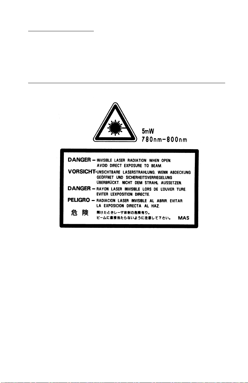
The following laser notice labels may be affixed to this printer as
shown:
Laser advis o ry label
Laser Notices vii
Page 8

4048-00x
Laser Not ice
The printer is certified in the U.S. to conform to the requirements of
DHHS 21 CFR Subchapter J for Class I (1) laser products, and
elsewhere is certified as a Class I laser product conforming to the
requirements of IEC 60825-1.
Class I laser products are not considered to be hazardous. The
printer contains internally a Class IIIb (3b) laser that is nominally a 5
milliwatt gallium arsenide laser operating in the wavelength region of
770-795 nanometers. The laser system and printer are designed so
there is never any human access to laser radiation above a Class I
level during normal operation, user maintenance, or prescribed
service condition.
Laser
Der Drucker erfüllt gemäß amtlicher Bestätigung der USA die
Anforderungen der Bestimmung DHHS (Department of Health and
Human Services) 21 CFR Teil J für Laserprodukte der Klasse I (1).
In anderen Ländern gilt der Drucker als Laserprodukt der Klasse I,
der die Anforderungen der IEC (International Electrotechnical
Commission) 60825-1 gemäß amtlicher Bestätigung erfüllt.
Laserprodukte der Klasse I gelten als unschädlich. Im Inneren des
Druckers befindet sich ein Laser der Klasse IIIb (3b), bei dem es
sich um einen Galliumarsenlaser mit 5 Milliwatt handelt, der Wellen
der Länge 770-795 Nanometer ausstrahlt. Das Lasersystem und der
Drucker sind so konzipiert, daß im Normalbetrieb, bei der Wartung
durch den Benutzer oder bei ordnungsgemäßer Wartung durch den
Kundendienst Laserbestrahlung, die die Klasse I übersteigen würde,
Menschen keinesfalls erreicht.
viii Service Manual
Page 9

4048-00x
Avis relatif à l’utilisation de laser
Pour les Etats-Unis : cette imprimante est cert ifiée conforme aux
provisions DHHS 21 CFR alinéa J concernant les produits laser de
Classe I (1). Pour les autres pays : cette imprimante répond aux
normes IEC 60825-1 relatives aux produits laser de Classe I.
Les produits laser de Classe I sont considérés comme des produits
non dangereux. Cette imprimante est équipée d’un laser de Classe
IIIb (3b) (arséniure de gallium d’une puissance nominale de 5
milliwatts) émettant sur des longueurs d’onde comprises entre 770
et 795 nanomètres. L’imprimante et son système laser sont conçus
pour impossible, dans des conditions normales d’utilisation,
d’entretien par l’utilisateur ou de révision, l’exposition à des
rayonnements laser supérieurs à des rayonnements de Classe I .
Avvertenze sui prodotti laser
Questa stampante è certificata negli Stati Uniti per essere conforme
ai requisiti del DHHS 21 CFR Sottocapitolo J per i prodotti laser di
classe 1 ed è certificata negli altri Paesi come prodotto laser di
classe 1 conforme ai requisiti della norma CEI 60825-1.
I prodotti laser di classe non sono considerati pericolosi. La
stampante contiene al suo interno un laser di classe IIIb (3b)
all’arseniuro di gallio della potenza di 5mW che opera sulla
lunghezza d’onda compresa tra 770 e 795 nanometr i. Il sistema
laser e la stampante sono stati progettati in modo tale che le
persone a contatto con la stampante, durante il normale
funzionamento, le operazioni di servizio o quelle di assistenza
tecnica, non ricevano radiazioni laser superiori al livello della
classe 1.
Laser Notices ix
Page 10

4048-00x
Avisos sobre el láser
Se certifica que, en los EE.UU., esta impresora cumple los
requisitos para los productos láser de Clase I (1) establecidos en el
subcapítulo J de la norma CFR 21 del DHHS (Departamento de
Sanidad y Servicios) y, en los demás países, reúne todas las
condiciones expuestas en la norma IEC 60825-1 para productos
láser de Clase I (1).
Los productos láser de Clase I no se consideran peligrosos. La
impresora contiene en su interior un láser de Clase IIIb (3b) de
arseniuro de galio de funcionamiento nominal a 5 milivatios en una
longitud de onda de 770 a 795 nanómetros. El sistema láser y la
impresora están diseñados de forma que ninguna persona pueda
verse afectada por ningún tipo de radiación láser superior al nivel de
la Clase I durante su uso normal, el mantenimiento realizado por el
usuario o cualquier otra situación de servicio técnico.
Declaração sobre Laser
A impressora está certificada nos E.U.A. em conformidade com os
requisitos da regulamentação DHHS 21 CFR Subcapítulo J para a
Classe I (1) de produtos laser. Em outros locais, está certificada
como um produto laser da Classe I, em conformidade com os
requisitos da norma IEC 60825-1.
Os produtos laser da Classe I não são considerados perigosos.
Internamente, a impressora contém um produto laser da Classe IIIb
(3b), designado laser de arseneto de potássio, de 5 milliwatts
,operando numa faixa de comprimento de onda entre 770 e 795
nanómetros. O sistema e a impressora laser foram concebidos de
forma a nunca existir qualquer possiblidade de acesso humano a
radiação laser superior a um nível de Classe I durante a operação
normal, a manutenção feita pelo utilizador ou condições de
assistência pres critas.
x Service Manual
Page 11

4048-00x
Laserinformatie
De printer voldoet aan de eisen die gesteld worden aan een
laserprodukt van klasse I. Voor de Verenigde Staten zijn deze eisen
vastgelegd in DHHS 21 CFR Subchapter J, voor andere landen in
IEC 60825-1.
Laserprodukt en van klasse I worden niet als ongevaarlijk
aangemerkt. De printer is voorzien van een laser van klasse IIIb
(3b), dat wil zeggen een gallium arsenide-laser van 5 milliwatt m e t
een golflengte van 770-795 nanometer. Het lasergedeelte en de
printer zijn zo ontworpen dat bij normaal gebrui k, bij onderhoud of
reparatie conform de voorschriften , nooit blootste lling mogelijk is
aan laserstraling boven een niveau zoals voorgeschreven is voor
klasse 1.
Lasermeddelelse
Printeren er godkendt som et Klasse I-laserprodukt, i
overenstemmelse med kravene i IEC 60825-1.
Klasse I-laserprodukter betragtes ikke som farlige. Printeren
indeholder internt en Klasse IIIB (3b)-laser, der nominelt er en 5
milliwatt galliumarsenid laser , som arbejder på bølgelængdeområdet
770-795 nanometer. Lasersystemet og printeren er udformet
således, at mennesker aldrig udsættes for en laserstråling over
Klasse I-niveau ved normal drift, brugervedligeholdelse eller
obligatoriske servicebetingelse r.
Laser Notices xi
Page 12

4048-00x
Huomautu s las er laitteesta
Tämä kirjoitin on Yhdysvalloissa luokan I (1) laserlaitteiden DHHS
21 CFR Subchapter J -määrityksen mukainen ja muualla luokan I
laserlaitteiden IEC 60825-1 -määrityksen mukainen.
Luokan I laserlaitteiden ei katsota olevan vaarallisia käyttäjälle.
Kirjoittimessa on sisäinen luokan IIIb (3b) 5 milliwatin
galliumarsenidilaser, joka toimii aaltoalueella 770 - 795 nanometriä.
Laserjärjestelmä ja kirjoitin on suunniteltu siten, että käyttäjä ei
altistu luokan I määrityksiä voimakkaammalle säteilylle kirjoittimen
normaalin toiminnan, käyttäjän tekemien huoltotoimien tai muiden
huoltotoimien yhteydessä.
VARO! Avattaessa ja suojalukitus ohitettaessa olet alttiina
näkymättömälle lasersäteilylle. Älä katso säteeseen.
VARNING! Osynlig laserstrålning när denna del är öppnad och
spärren är urkopplad. Betrakta ej strålen.
Laser-notis
Denna skrivare är i USA certifierad att motsvara kraven i DHHS 21
CFR, underparagraf J för laserprodukter av Klass I (1). I andra
länder uppfyller skrivaren kraven för laserprodukter av Klass I enligt
kraven i IEC 60825-1.
Laserprodukter i Klass I anses ej hälsovådliga. Skrivaren har en
inbyggd laser av Klass IIIb (3b) som består av en laserenhet av
gallium-arsenid på 5 milliwatt som arbetar i våglängdsområdet 770795 nanometer. Lasersyst emet och skrivaren är utfo rmade så att det
aldrig finns risk för att någon person utsätts för laserstrålning över
Klass I-nivå vid normal användning, underhåll som utförs av
användaren eller annan föreskriven serviceåtgärd.
xii Service Manual
Page 13

4048-00x
Laser-melding
Skriveren er godkjent i USA etter kravene i DHHS 21 CFR,
underkapittel J, for klasse I (1) laserprodukter, og er i andre land
godkjent som et Klasse I-laserproduk t i samsvar med kravene i IEC
60825-1.
Klasse I-laserprodukter er ikke å betrakte som farlige. Skriveren
inneholder internt en klasse IIIb (3b)-laser, som består av en
gallium-arsenlaserenhet som avgir stråling i bølgelengdeområdet
770-795 nanometer. Lasersystemet og skriveren er utformet slik at
personer aldri utsettes for laserstråling ut over klasse I-nivå under
vanlig bruk, vedlikehold som utføres av brukeren, eller foreskrevne
serviceopera sjoner.
Avís sobre el Làser
Segons ha estat certificat als Estats Units, aquesta impressora
compleix els requisits de DHHS 21 CFR, apartat J, pels productes
làser de classe I (1), i segons ha estat certificat en altres llocs, és un
producte làser de classe I que compleix els requisits d’IEC 60825-1.
Els productes làser de classe I no es consideren perillosos. Aquesta
impressora conté un làser de classe IIIb (3b) d’arseniür de gal.li,
nominalment de 5 mil.liwats, i funciona a la regió de longitud d’ona
de 770-795 nanòmetres. El sistema làser i la impressora han sigut
concebuts de manera que mai hi hagi exposició a la radiació làser
per sobre d’un nivell de classe I durant una operació normal, durant
les tasques de manteniment d’usuar i ni durant els serveis que
satisfacin les condicions prescrites.
Laser Notices xiii
Page 14
4048-00x
Japanese Laser Notice
Chinese Laser Notice
xiv Service Manual
Page 15
4048-00x
Korean Laser Notice
Laser Notices xv
Page 16

4048-00x
xvi Service Manual
Page 17

4048-00x
Safety Information
• The safety of this product is based on testing and approvals of
the original design and specific components. The manufacturer
is not responsible for safety in the event of use of unauthorized
replacement par ts.
• The maintenance information for this product has been
prepared for use by a professional service person and is not
intended to be used by others.
• There may be an increased risk of electric shock and personal
injury during disassembly and servicing of this product.
Professional service personnel should understand this and take
necessary precaut ions.
• Use of this symbol throughout the service manual indicates the
presence of hazardous voltage in the repair work area. Unplug
the printer before proceeding or proceed with caution, if repair
work requires power.
Consignes de Sécurité
• La sécurité de ce produit repose sur des tests et des
agréations portant sur sa conception d'orig ine et sur des
composants particuliers. Le fabricant n'assume aucune
responsabilité concernant la sécurité en cas d'utilisation de
pièces de rechange non agréées.
• Les consignes d'entretien et de réparation de ce produit
s'adressent uniquement à un personnel de maintenance
qualifié.
• Le démontage et l'entretien de ce produit pouvant présenter
certains r isques électr iqu es, le personnel d'entretien qualifié
devra prendre toutes les précautions nécessaires.
Safety Information xvii
Page 18

4048-00x
Norme di sicurezza
• La sicurezza del prodotto si basa sui test e sull'approvazione
del progetto originale e dei componenti specifici. Il produttore
non è responsabile per la sicurezza in caso di sostituzione non
autorizzata delle parti.
• Le informazioni riguardanti la manutenzione di questo prodotto
sono indirizzate soltanto al personale di assistenza autorizzato.
• Durante lo smontaggio e la manutenzione di questo prodotto,
il rischio di subire scosse elettriche e danni alla persona è più
elevato. Il personale di assistenza autorizzato, deve, quindi,
adottare le precauzioni necessarie.
Sicherheitshinweise
• Die Sicherheit dieses Produkts basiert auf Tests und
Zulassungen des ursprünglichen Modell s und bestimmter
Bauteile. Bei Verwendung nicht genehmigter Ersatzteile wird
vom Hersteller keine Verantwortung oder Haftung für die
Sicherheit übernommen.
• Die Wartungsinformationen für dieses Produkt sind
ausschließlich für die Verwendung durch einen
Wartungsfachmann bestimmt.
• Während des Auseinandernehme ns und der Wartung des
Geräts besteht ein zusätzliches Risiko eines elektrischen
Schlags und körperlicher Verletzung. Das zuständige
Fachpersonal sollte entsprechende Vorsichtsmaßnahmen
treffen.
xviii Service Manual
Page 19

4048-00x
Pautas de Seguridad
• La seguridad de este producto se basa en pruebas y
aprobaciones del diseño original y componentes espec íficos.
El fabricante no es responsable de la seguridad en caso de uso
de piezas de repuesto no autorizadas.
• La información sobre el mantenimiento de este producto está
dirigida exclusivamente al personal cualificado de
mantenimiento.
• Existe mayor riesgo de descarga eléctrica y de daños
personales durante el desmontaje y la reparación de la
máquina. El personal cualificado debe ser consciente de este
peligro y tomar las precauciones necesarias.
Informações de Segurança
• A segurança deste produto baseia-se em testes e aprovações
do modelo original e de componentes específicos. O fabricante
não é responsável pela segunrança, no caso de uso de peças
de substituição não autorizadas.
• As informações de segurança relativas a este produto
destinam-se a profissionais destes serviços e não devem ser
utilizadas por outras pessoas.
• Risco de choques eléctricos e ferimentos graves durante a
desmontagem e manutenção deste produto. Os profissionais
destes serviços devem estar avisados deste facto e tomar os
cuidados necessários.
Safety In fo rmation xix
Page 20
4048-00x
Inf ormació de Seguretat
• La seguretat d'aquest producte es basa en l'avaluació i
aprovació del disseny original i els components específics.
El fabricant no es fa responsable de les qüestions de
seguretat si s'utilitzen peces de recanvi no autoritzades.
• La informació pel manteniment d’aquest producte està
orientada exclusivament a professionals i no està destinada
a ningú que no ho sigui.
• El risc de xoc elèctric i de danys personals pot augmentar
durant el procés de desmuntatge i de servei d’aquest producte.
El personal professional ha d’estar-ne assabentat i prendre
les mesures convenie n ts.
xx Service Manual
Page 21

4048-00x
Safety In fo rmation xxi
Page 22

4048-00x
Preface
This manual contains maintenance procedures for service
personnel. It is divided into the following chapters:
1. General Informati on contains a general description of the
printer and the maintenance approach used to repair it. Special
tools and test equipment are listed in this chapter, as well as
general environmental and safety instructions.
2. D iagnostic Information contains an error indicator table,
symptom tables, and service checks used to isolate failing field
replaceable units (FRUs).
3. D iagnostic Aids contains tests and checks used to locate or
repeat symptoms of printer problems.
4. Repair Information provides instructions for making printer
adjustments and removing and installing FRUs.
5. Locations uses illustrations and tables to identify the locations
and test points on the printer.
6. Preventive Maintenance contains the lubrication specifications
and recommendations to prevent problems.
7. Parts Ca t a l o g contains illustrations and part numbers for
individual FRUs.
xxii Service Manual
Page 23

4048–00x
1. Gen e r a l Informat io n
The Lexmark™ T420(n) laser printer is a monochrome laser printer
designed for single users or small workgroups. There are two
models:
• The T420 Base printer, with 16MB of memory standard , a
parallel port, and a USB port.
• The T420 Network printer, with 32MB of memory standa rd, an
integrated Ethernet adapter, a parallel port, and a USB port.
The purpose of this chapter is to provide an overview of the
capabilities of the printer and available options for each of the
T420 models.
Note: Unless otherwise noted, all references to the Lexmark
T420(n) laser printer are intended to refer equally to both the
T420 Base and the T420 Network models.
Maintenance Approach
The diagnostic information in this manual leads you to the correct
field replaceable unit (FRU) or part. Use the error code charts,
symptom index, and service checks to determine the symptom and
repair the failure. See “Diagnostic In formation” on page 2-1 , for
the location of each section. See the “Repair Information” on
page 4-1 to help identify parts. After completing the repair, perform
tests as needed to verify the repair.
Special Tools
Long Phillips screwdriver (approximately 6–inch shank)
Slotted screwdriver
Small Ph illips screwdr iver
When taking voltage readings, always use the printer frame as
ground unless another ground is specified.
General Information 1-1
Page 24
4048–00x
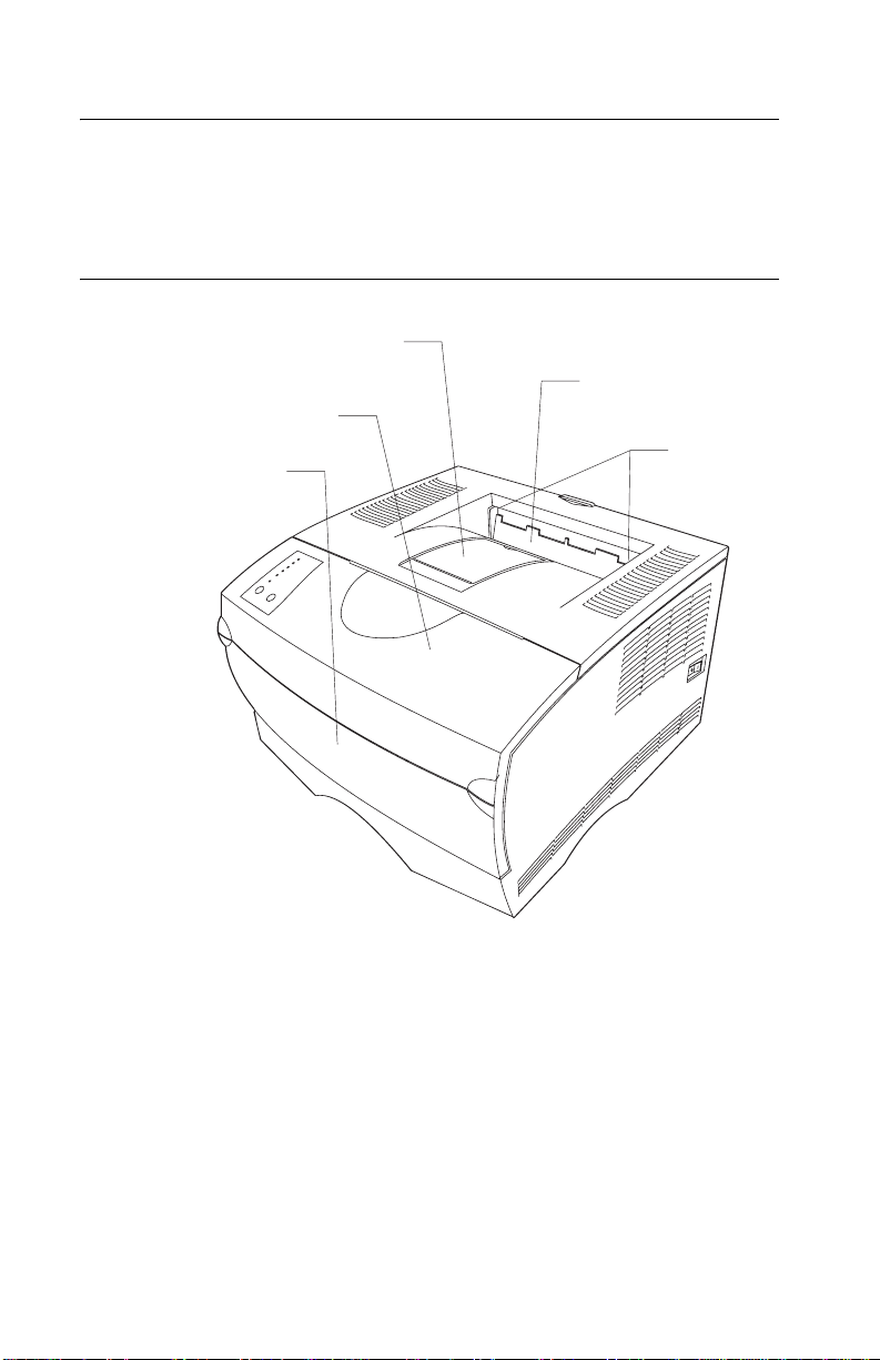
Serial Number
Look for the serial number label on the inside front cover of the
printer.
Printer Identification
Flap
Duct cover Asm
Front cover
Cover MPF Asm
(MPF door)
Flags
1-2 Service Manual
Page 25

4048–00x
Printer Features
Memory and User Flash Memory
Each model has a standard amount of memory (RAM) soldered on the system
card, and a certain number of 100-pin DIMM slots available f or installing
additional memory or user fl ash m emory opti ons.
Memory Base Model Network Model
Standard memory 16MB 32MB
Standard flash memory None None
Memory options
•8MB DIMM
•16MB DIMM
•32MB DIMM
•64MB DIMM
• 128MB DIMM
Maximum # of memory
DIMM
Maximum possible
memory
Flash memory options
• 2MB DIMM
• 4MB DIMM
• 8MB DIMM
•16MB DIMM
Maximum # of flash
memory DIMMs
Maximum possible flash
memory
✓
✓
✓
✓
✓
22
272MB 288MB
✓
✓
✓
✓
11
16MB 16MB
Note: ✓ Indicates option is suppor ted .
✓
✓
✓
✓
✓
✓
✓
✓
✓
General Information 1-3
Page 26

4048–00x
Resolution and Print Quality
Note:
• IET , PQET, PictureGrade™, print resolution, print darkness, and
toner saver can all be set independently of each other through
the data stream.
• Control panel menus allow a user to independently set PQET ,
PictureGrade, and print resolution.
• The IET setting is implicitly selected when a particular print
resolution is selected using the Quality Menu.
• Toner saver and print darkness settings are implicitly set when a
particula r toner darkness is selected using the Quality Me nu.
Print Quality Settin g Base Model Network Model
Print re s o lu tio n :
• 300 dpi
• 600 dpi
• 1200 IQ dpi
Image Enhancement
Technology (IET):
2 Bits /Pel ✓✓
PQET ✓✓
Toner saver ✓✓
Print darkness ✓✓
PictureGrade ✓✓
Note:
✓ Indicates print quality setting is supported.
✓
✓
✓
✓
✓
✓
1-4 S er v ice M anual
Page 27

4048–00x
Print Area
The following print area settings are available.
Print Area Option Base M odel Network Model
Normal ✓✓
Fit to page ✓✓
Edge to edge ✓✓
General Information 1-5
Page 28

4048–00x
Print Media
The following table shows the supported media, medi a weights and
media textures which together are used to select a technology
operating point to provide optimal print quality across a variety of
media.
Media Base Model Network Model
Media Operating Points
Paper ✓✓
Card stock ✓✓
Transparency ✓✓
Labels ✓✓
Envelope ✓✓
Cotton paper ✓✓
Bond ✓✓
Media Weigh ts
Heavy ✓✓
Normal ✓✓
Light ✓✓
Media T extures
Rough ✓✓
Normal ✓✓
Smooth ✓✓
Note:
✓ Indicates media is supported.
1-6 S er v ice M anual
Page 29

4048–00x
Printer Data Streams
Data Stream s Base Model Network Model
PCL 6 emulation ✓✓
Post Scri pt Level 2
emulation
PPDS ✓✓
Note: ✓ Indicates data stream is support ed.
✓✓
• PCL 6 emulation includes the PCL 5e and PCL XL interpreters,
and is fully compatible with Hewlett Packard’s LaserJet 5 Family.
Furthermore, the printer PCL emulation is backward compatible
with the Optra™ T 610/612/614/616 and other members of
Lexmark’s Optra family of laser printers.
• 4048–00x supports version 3010 of the Adobe definition of
PostScript 3, and the interpreter is backward compatible with
the Optra T 610/612/614/616 and other members of Lexmark’s
Optra family of laser printers.
• PPDS is backward compatible with Optra T 610/612/614/616
and Lexmark’s Optra family of laser printers. The PPDS
interpreter is inactive as a factory default. It must be activated
using a PJL command or operator panel operation before it can
be used.
General Information 1-7
Page 30
4048–00x
Fonts
Fonts / Options Base Model Network Model
PCL bitmapped 2 2
PCL scalable 90 90
PS scalable 89 89
PPDS bitmapped 5 5
PPDS scalable 39 39
Paper Handling
Paper Handling Base Model Network Model
Standard
Standard input sources:
• Integrated 250–sheet
tray
The 250 sheet
drawer supports the
following siz es: A4,
A5, JIS B5, folio,
letter, legal,
executive, and
statement.
• Multipurpose feeder
Standard output
destination
• 150–sheet sensing bin
Standard duple x ✓✓
Envelope conditioning ✓✓
2
1
1
1
1
2
1
1
1
1
1-8 S er v ice M anual
Page 31

4048–00x
Paper Handling Base Model Net work M odel
Universal paper size
• Minimum bitmap width
and length
• Maximum bitmap width
• Maximum bitmap
length
Options
Maximum # of optional
drawers
Optional drawers:
• 250–sheet drawer
• 500–sheet drawer
The 500 sheet
drawer supports the
following sizes: A4,
JIS B5, folio, letter,
legal, and executive.
Max im um # of media
input sources
Maximum input sheet
capacity (excluding
envelopes)
✓
64800
183600
306000
11
✓
✓
33
850 850
✓
64800
183600
306000
✓
✓
Maximum sheet capacity
(excluding envel opes)
Note:
✓ Indicates associated capability is support ed.
Assumes 20 lb xerographic paper.
150 150
General Information 1-9
Page 32

4048–00x
Connectivity
Attachments Base Model Network Model
Standard parallel
interface
Parallel interface
connector is a
1284–B connector.
Par allel mode 2 ✓✓
Standard USB interface ✓✓
Standard Ethernet 10/
100 Base–TX
✓✓
✗
✓
Note:
✓ Indicates attachment is part of the model factory shipped
configuration.
✗ Indicates attachment is not par t of the model factory
shipped configuration.
1-10 Service Manual
Page 33

4048–00x
Printer Speed
Speed Base Model Network Model
Pages/ minute in 300 dpi 22 22
Pages/ minute in 600 dpi 22 22
Pages/minute in 1200
Image Quality
Time to first print 10 seconds 10 seconds
Automatic power saver 8 8
22 22
RIP Card Specifications
Feature Base Model Network Model
Processor 922T 922T
Processor/Bus frequency 200/100 MHz 200/100 MHz
Synchronous DRAM 2–64 Mbit 2–128 Mbit
NAND flash 1–64 Mbit 1–64 Mbit
Processor internal bus
width capabilit y
RIP SRAM 0KB 0KB
L1 Cache (instruction/
data)
32 Bit 32 Bit
8KB / 8KB 8KB / 8KB
General Information 1-11
Page 34

4048–00x
Supplies
Print Cartridge Average Yield
Prebate™ print
cartridges
Regular cartridges
(without Prebate terms
and conditions)
5,000
10,000
5,000
10,000
Approximate
Coverage
5%
5%
5%
5%
Operator Panel
The 4048–00x operator panel consists of six light’s and two buttons.
The operator panel is used to indicate status as well as an input to
modify some printer settings. All models have the same operator
panel.
Ready/Data light is on
Toner Low light is off
Load/Remove Paper light is blinking
Paper Jam light is blinking slowly
Error light is off
Press Continue light is off
Continue button
Cancel button
Note: Printer settings such as paper source, paper size, and
orientation may not be selected or modified by the operator panel.
Instead, users must utilize an application print driver and/or the
printer toolkit to modify settings through the host computer. A printer
settings page can be printed by briefly pressing Continue when only
the Ready/Data light is on.
1-12 Service Manual
Page 35

4048–00x
Options
See “Options” on page 7-18 for a list of options available for the
T420(n) printer.
General Information 1-13
Page 36

4048–00x
Acronyms
CCharge Roll
CCW Counterclockwise
CW Clockwise
DC Direct Current
DEV Developer Roll
DIMM Dual Inline Memory Module
DRAM Dynamic Random Access Memory
FRU Field Replaceable Unit
GND Ground
HVPS High Voltage Power Supply
IDE I ntegrated De velopment Envi ronment
IET Image Enhancement Technology
INA Internal Network Adapter
KB Kilobyte
LED Light–Emitti ng Diode
LSU Laser Scanning Unit
LVPS Low Voltage Power Supply
MHz Megahertz
MPF Multipurpose Feeder
NAND Not And (Gate)
NVRAM Nonvolatile Random Access Memory
PCB Printed Circuit Board
PCL 6 Printer Command Language
PJL Printer Job Languag e
POR Power–On Reset
POST Power–On Self Test
PPDS Personal Printer Data Stream
PQET Print Quality Enhancement Technology
PS PostScript
PWB Print ed Wiring Board
RIP Raster Image Processor
ROM Read Only Memory
RS Recommended Standard
T Transfer (Roll)
TAR Toner Adder Roll
USB Universa l S e rial Bus
V ac Volt s Alt ernat ing Current
1-14 Service Manual
Page 37

4048–00x
2. Diagnostic Information
Start
CAUTION: Unplug power from the printer before connecting or
disconnecting any cable, assembly, or electronic card. This is a
precaution for personal safety and to prevent damage to the printer.
This chapter contains the codes and diagnostic tools to aid in
providing corrective action for a malfunctioning printer.
The lights on the operator panel indicate the status of the printer
anytime it is powered on. When the printer experiences a problem
requiring operator intervention, it indicates the source by blinking
one or more lights. See “Status Information Light Patterns” on
page 2-3 for more information. When all six lights blink
simultaneously , a service may need to be performed. See “S ervice
Error Codes” on page 2-11 for more information.
If the printer does not indicate a service error code nor complete
POST without an error but there is a symptom, see “Symptom
Tables” on page 2-26 for more information.
Diagnostic Information 2-1
Page 38

4048–00x
Operator Panel
The 4048–00x operator panel consists of six indicator lights and two
buttons.
Ready/Data
Toner Low
Load/Remove
Paper
Paper Jam
Error
Press Continue
Continue
Cancel
Note: Traditional printer settings such as paper source, paper size,
and orientation may not be selected or modified using the operator
panel. Users must either utilize an application print driver and/or the
printer toolkit to modify settings.
The operator panel may be used for:
• Determining printer status (See “Status Infor mati o n Lig h t
Patterns” on pa ge 2-3 for more information.)
• Reviewing printer settings (See “Power–On Self Test (POST)”
on page 2-26 for more information.)
• Changing printer settings (See “Power–On Operations” on
page 2-25 for more information.)
• Utilizing diagnostic tools (See “Power–On Operations” on
page 2-25 for more information.)
• Obtaining information about printer service errors (See
“Service Error Codes” on page 2-11 for more information.)
2-2 S er v ice M anual
Page 39

4048–00x
Light Patt ern s
The following symbols are used in the status, attendance, and
service information tables.
❍ Ligh t i s o ff.
● Light is on solid.
✳ Light is blinking.
✕ Light is blinking slowly.
Status Information Light Patterns
Status
Ready/Data
T oner Low
Load/Remove Paper
Paper Jam
Error
Press Continue
●❍❍❍❍❍Ready
●❍❍❍❍✳Demo Ready
✕❍❍❍❍❍Hex Trace Ready
✳❍❍❍❍❍Busy
●❍❍❍❍●Waiting
●●❍❍❍❍Ready, with Toner Low
●●❍❍❍✳Demo Ready, with Toner Low
✕ ●❍❍❍❍Hex Trace Ready, with Toner
✳ ●❍❍❍❍Busy, with Toner Low Warning
●●❍❍❍●Waiting, with Toner Low
✳❍❍❍✳❍Flushing
Warning
Warning
Low Warning
Warning
Diagnostic Information 2-3
Page 40

4048–00x
Ready/Data
To ner Low
Status
Load/Remove Paper
Paper Jam
Error
Press Continue
●●●●●●Canceling Job/Res ett ing
All lights cycl ing Restarting P r in te r
❍❍●●❍❍Diagnostics–Memory Test
●●●❍❍❍Programmi ng System Code–
✳✳✳❍❍❍Programming System Code
●❍❍❍●❍Invalid Engine Code/Invalid
Printer/Activating Changes
DO NOT POWER OFF
Note: The Error and
Press Continue lights
cycle through four diff erent
patt erns to i n dicate
progress during
programming.
Partially Complete–Download
System Code Data
Network Code
Note: A double press of
Continue, causes a
secondary light pattern
which indicates further
information on the type of
invalid code status exists.
See “Invalid Code
Secondary Light
Patterns” on page 2-5.
2-4 S er v ice M anual
Page 41

4048–00x
Invalid Code Seco ndary Light Pattern s
Status
Ready/Data
T oner Low
Load/Remove Paper
Paper Jam
Error
Press Continue
●❍●❍●❍Invalid Engine Code
●❍✳❍●❍Invalid Network Code
Attendance Information Light Pattern s
Attendance Condition
Ready/Data
T oner Low
Load/Remove Paper
Paper Jam
Error
Press Continue
❍❍●❍❍●Load Paper–Tray 1, Tray 2 or
MPF
❍❍✳ ❍❍● Load Paper–Manual Feed
❍❍●❍❍✳ Load Paper–Tray 1 for Side 2
Manual Duplex
❍❍●❍❍❍Remove Paper from Output
Bin
❍❍●❍●❍Insert Tray 1
❍❍❍❍●❍Top Cover Open/Cartridge
Missing
❍✳ ❍❍● ❍Defectiv e or Unsu pported Print
Cartridge
❍✳ ❍❍✳ ❍Change Cartridge–Invalid
Refill
Diagnostic Information 2-5
Page 42

4048–00x
Attendance Condition
Ready/Data
To ner Low
❍●❍❍❍●Toner Low Intervention
❍❍❍❍❍●Offline
❍❍❍●❍●Paper Jam
❍❍❍❍●●Printer Error
Load/Remove Paper
Paper Jam
Error
Press Continue
Note: A double press of
Continue causes a
secondary light pattern
which indicates further
information on the type of
paper jam. See “Paper
Jam Secondary Light
Patterns” on page 2-7.
2-6 S er v ice M anual
Note: A double press of
Continue causes a
secondary light pattern
which indicates further
information on the type of
printer error. See “Printer
Error Secondary Light
Patterns” on page 2-8.
Page 43

4048–00x
Paper Jam Secondary Light Patterns
Attendance Condition
Ready/Data
T oner Low
Load/Remove Paper
Paper Jam
Error
Press Continue
●❍❍●❍●Paper Jam–Input Sens or
❍●❍●❍● Paper Jam–Exit Sensor
❍✳ ❍● ❍●Paper Jam–Duplex Sensor
❍❍●●❍● Paper Jam–Fuser Exit Sensor
✳❍❍●❍●Paper Jam–Multipurpose
Feeder Sensor
Diagnostic Information 2-7
Page 44

4048–00x
Printer Error Secondary Light Patterns
To obtain the secondary light pattern, quickly press Continue twice.
Attendance Condition
Ready/Data
Toner Low
●❍❍❍●● Complex Page
❍●❍❍●● Insufficient Collation Area
❍❍●❍●● Defective Flash
❍❍❍●●● Network Interface Error
Load/Remove Paper
Paper Jam
Error
Press Continue
✳ ❍❍❍● ●Resource Save Off–Deficient
❍✳ ❍❍● ●PPDS Font Error
❍❍✳ ❍● ●Insufficient Defrag Memory
❍❍❍✳ ● ●ENA Connection Lost
●●❍❍● ● Memor y Full
●❍●❍●●Short Paper
●❍❍●●●Flash Full
❍●●❍●●Too Many Flash Options
❍●❍●● ● Engine Code Failure
Memory
2-8 S er v ice M anual
Page 45

4048–00x
Service Information Light Patterns
Service Condition
Ready/Data
T oner Low
Load/Remove Paper
Paper Jam
Error
Press Continue
✳✳✳✳✳✳Service Error
Note: A double press of
Continue causes a
secondary light pattern
which indicates further
information on the type of
printer er r or. S e e “Service
Error Codes” on
page 2-11 for m o re
information.
Diagnostic Information 2-9
Page 46

4048–00x
Service Error Secondary Light Patterns
Quickly press and release Continue twice to obtain the secondary
light pattern.
Service Condition
Ready/Data
Toner Low
✳ ❍❍❍❍❍Software Error (90x)
✳ ❍❍❍❍✳ Transfer Roll Error (91x)
✳ ❍❍❍✳ ❍Fuser/Toner Sens or Error (92x)
✳ ❍❍❍✳ ✳ Printhead / Transport Motor
✳ ❍❍✳ ❍❍Controller Card (94x)
Load/Remove Paper
Paper Jam
Error
Press Continue
Error (9 3 x)
✳ ❍❍✳ ❍✳ NVRAM / ROM / NAND Error
(95x)
✳❍❍✳✳❍RAM Memory Error (96x)
✳❍❍✳✳✳Network Error (97x)
✳❍✳❍❍❍Paper Port Communication
Error (9 8 x)
Note: There are many tertiar y codes following these secondary
codes. The following pages show these codes.
2-10 Service Manual
Page 47

4048–00x
Obtaining Information about Printer Service Error Codes
All lights flashing simultaneously on the panel designates a printer
service error as a primar y code. Double press Continue to see the
secondary codes; double press Continue again to see the tertiary
codes; double press Continue the third time to return to the primary
code.
All secondary codes have a flashing Ready/Data light but not the
Toner Low light. All tertiary codes have a flashing Toner Low light
but not a Ready/Data light.
All lights flashing simultaneously, as a result of sending data to the
printer, may indicate a code problem. Call Lexmark Customer
Service at 1–800–539–6275 for assistance.
Service Error Codes
Service error codes are generally non–recoverable except in an
intermittent condition when you can POR the printer to temporarily
recover from the error condition.
RIP Software Erro r / Il le gal Trap
Contact the next level of support or call Lexmark 1–800–539–6275
for assistance.
(900)
Note: The alarm is not actuated for this error.
Diagnostic Information 2-11
Page 48

4048–00x
Engine Flash or Engine Sof tware Error
The first error message below (901) indicates the flash into which
the engine code is programmed is bad. Either the flash cannot be
erased or the program failed when programming was attempted.
The remaining errors, 902–906, indicate an unrecoverable engine
software error. Replace the RIP card.
Primary Code Secondary Code
Ready/Data
Toner Low
Load/
Remove Paper
Paper Jam
Error
Ready/Data
Toner Low
Load/
Remove Paper
Paper Jam
Error
Press Continue
Tertiary Codes
Press Continue
Ready/Data
Toner Low
Load/
Remove Paper
Paper Jam
Error
Press Continue
RIP interface driver error (906).
Interface violation by paper port
device (905).
Interface violation by RIP (904).
Paper port link drive error (903).
General engine software error (902).
Note: If the alarm control is turned on, the alarm does s ound when
this error occurs.
2-12 Service Manual
Page 49

4048–00x
Transfer Roll Error
Indicates a problem in the transfer roll area. Check the cable from
the HVPS (CN1) to t he cont roll er car d (J 3). Al so c heck the vo ltage at
pin #4 of J3.
(917)
Note: If the alarm control is turned on, the alarm does sound when
this error occurs.
Diagnostic Information 2-13
Page 50

4048–00x
Fuser Error
Indicates a problem with the fuser. See the “Fuser Service Check”
on page 2-34 for more information.
Incorrect fuser lamp instal led (925).
Open circuit in thermist or path (924).
Fuser too hot during printing or idl e (923).
Fuser failed to reach standby temperature (922).
Fuser below standby temperature at idle (921).
Fuser below temperature when printing ( 920).
Note: If the alarm control is turned on, the alarm does s ound when
this error occurs.
2-14 Service Manual
Page 51

4048–00x
Fan Stalled
This error indicates a printer fan stall.
Primary Code Secondary Code Tertiary Codes
Ready/Data
Toner Low
Load/
Remove Paper
Paper Jam
Error
Press Continue
Ready/Data
Toner Low
Load/
Remove Paper
Paper Jam
Error
Press Continue
Ready/Data
Toner Low
Load/
Remove Paper
Paper Jam
Error
Press Continue
(927)
T oner Sensor Error
Indicates a problem with either the toner sensor or print cartridge.
(929)
Note: If the alarm control is turned on, the alarm does sound when
this error occurs.
Diagnostic Information 2-15
Page 52

4048–00x
Printhead Error
Indicates a problem with the printhead. Check cables to the
printhead. Replace the printhead as necessary. See “Printhead
Assembly Adjustment” on page 4-2 for realignment procedures.
Mirror motor not at oper ating
speed (935). (Verify +24 V dc
on pin #5 of J7.)
Mirror motor lost lock (934).
Mirror motor locked, no hsync received
(933).
Printhead – lost hsync (932).
Printhead – no first hsync (931).
Printhead – wrong printhead installed (930).
Note: If the alarm control is turned on, the alarm does s ound when
this error occurs.
2-16 Service Manual
Page 53

4048–00x
Transport Motor Error
Indicates a problem with the main drive motor system. The problem
could be the motor, the RIP card, the cabling or the drive assembly.
Check the cable connectors. The tertiary code below, with four
flashing lights indicates a problem in the drive assembly.
Tra nsport motor
lost lock (937 ).
Transport motor initial
lock failure (936).
Note: If the alarm control is turned on, the alarm does sound when
this error occurs.
Diagnostic Information 2-17
Page 54

4048–00x
RIP to Engine C ommunication Failu re (C ontroller Card)
This error indicates that the RIP processor cannot communicate with
the engine processor.
Primary Code Secondary Code Tertiary Codes
Ready/Data
Toner Low
Load/
Remove Paper
Paper Jam
Error
Press Continue
Ready/Data
Toner Low
Load/
Remove Paper
Paper Jam
Error
Press Continue
Ready/Data
Toner Low
Load/
Remove Paper
Paper Jam
Error
Press Continue
(939)
RIP to Engine C ommunication Failu re (C ontroller Card)
This error indicates a failure in the z ero crossing signal which is used
for fuser control. It may indicate the wrong L V PS has been installed.
Primary Code Secondary Code Tertiary Codes
Ready/Data
Toner Low
Load/
Remove Paper
Paper Jam
Error
Ready/Data
Toner Low
Load/
Remove Paper
Paper Jam
Error
Ready/Data
Toner Low
Load/
Remove Paper
Paper Jam
Error
Press Continue
2-18 Service Manual
Press Continue
Press Continue
(940)
Page 55

4048–00x
Engine C ir cui t ry Failure (Controller Ca rd)
This error indicates a failure in the engine circuitry portion of the
controller card.
Primary Code Secondary Code
Ready/Data
Toner Low
Load/
Remove Paper
Paper Jam
Error
Press Continue
Tertiary Codes
Delay line calibration failure (949).
Ready/Data
Toner Low
Load/
Remove Paper
Paper Jam
Error
Press Continue
Ready/Data
Toner Low
Load/
Remove Paper
Paper Jam
Error
Press Continue
Pel clock check failure (948).
(947)
• PQET RAM test incomplete.
• PQET RAM test did not complete.
• PQET RAM test failed MARCH0.
• PQET RAM test failed MARCH1.
• PQET RAM test bu sy failure.
Diagnostic Information 2-19
Page 56

4048–00x
NVRAM Failure
This lighting sequence indicates a problem in the NVRAM. Replace
the RIP card assembly.
Primary Code Secondary Code Tertiary Codes
Ready/Data
Toner Low
Load/
Remove Paper
Paper Jam
Error
Ready/Data
Toner Low
Load/
Remove Paper
Paper Jam
Error
Ready/Data
Toner Low
Load/
Remove Paper
Paper Jam
Error
Press Continue
Press Continue
Press Continue
NVRAM chip
failure (954).
NVRAM CRC failure
(952).
Note:
– If the alarm control is turned on, the alarm does sound when
this error occurs.
– Always check printhead alignment after replacing the RIP
card assembl y . See “Printhead Assembly Adjustment” on
page 4-2 for hardware alignment of the printhead.
2-20 Service Manual
Page 57

4048–00x
RIP Card Error (ROM / NAND)
Indicates a failed RIP card assembly. Replace the RIP card.
SRAM failure (959).
NAND failure (958).
ASIC failure (957).
Processor failure (956).
Code ROM or NAND failed Cyc li c Redundancy Check
(CRC) (955).
Note:
– The alarm is not activated for this error.
– Always check printhead alignment after replacing the RIP
card assembly. See “Printhead Assembly Adjustment” on
page 4-2 for hardware alignment of the printhead.
Diagnostic Information 2-21
Page 58

4048–00x
RAM Memory Error
This error indicates RAM failure . Remove DIMM(s) and re–POR the
printer. If the error persists, replace the card. If the error subsides,
check each DIMM independently. Replace faulty DIMM.
RAM in slot 3 is bad (963).
RAM in slot 2 is bad (962).
RAM in slot 1 is bad (961).
RAM soldered on the board is bad (960).
Note: The alarm is not activated for this error.
2-22 Service Manual
Page 59

4048–00x
Network Error
Indicates an error in the network circuitry. Replace the RIP card
assembly.
Primary Code Secondary Code
Ready/Data
Toner Low
Load/
Remove Paper
Paper Jam
Error
Ready/Data
Toner Low
Load/
Remove Paper
Paper Jam
Error
Press Continue
Tertiary Codes
(971)
(970)
Note:
(972)
(973)
Press Continue
Ready/Data
Toner Low
Load/
Remove Paper
Paper Jam
Error
Press Continue
Flash parts failed
while programm ing
port (979).
Bad checksum while
programming port (978).
Unrecoverable softwar e error in
network port (975).
Unrecognizable network port (974).
– If the alarm control is turned on, the alarm does sound when this
error oc curs.
– Always check printhead alignment after replacing the RIP card
assembly. See “Printhead Assembly Adjustment” on pa ge 4-2
for hardware alignment of the printhead.
Diagnostic Information 2-23
Page 60

4048–00x
Paper Port Communication Failure
Indicates an error communicating with tray 2, if installed. Remove
tray 2 and recheck. If the error doesn’t recur, replace tray 2. If the
error recurs replace the RIP card assembly.
Invali d com m and parameter
received by specified device
(984).
Invalid command recei ved by
specified device (983).
Communications error detected by
specified de vice (982).
Engine protocol violation detected by the
specified device (981).
Engine experiencing unreliable communications to
specified device (980).
Note: Always check printhead alignment after replacing the RIP card
assembl y. See “Printhead Assembly Adjustment” on page 4-2 for
hardware alignment of the printhead.
2-24 Service Manual
Page 61

4048–00x
Power–On Operations
To access the printer operations for the 4048:
1. Turn off the printer .
2. Press and hold the buttons in the following table for the
operation needed.
3. Turn on the printer. Hold the buttons until the lights cycle on the
operator panel.
Operation Power–on action
Enter Configuration
Menu mode
Print the Print Quality
test pages
Enter Diagnostics
mode
Print the Print Quality
test pages
Reset NVRAM and
enter Normal mode
1. Power on with top cover open and Continue
pressed.
2. Close cover once the error lig ht i s display ed.
T op co ver open with Continue pr essed. ( Cartridge
Lockout function enabled)
1. Power on with top cover open and Cancel
pressed.
2. Close cover once the error lig ht i s display ed.
Top cover open with Cancel pressed. (Cartridge
Lockout function disabled)
1. Power on with top cover open and both
Continue and Cancel b uttons pressed.
2. Close cover once the error lig ht i s display ed.
Diagnostic Information 2-25
Page 62

4048–00x
Power–On Self Test (POST)
When you turn the printer on, it performs a Power–On Self Test.
Check for correct POST functioning of the base printer by observing
the following symptoms:
Symptom Tables
POST Symptom Table
Symptom Action
The main motor, cooling fan and
fuser do not come on.
POST completes e xcept one or
more lights do not come on.
None of the lights come on. See the “Operator Panel Service
Main motor does not come on. See the “Main Motor Service
Fan does not come on. See the “Cooling Fan Service
Fuser lamp does not come on. See the “Cold Fuser Service
Fuser lamp never turns off. See the “Hot Fuser Service
The paper feed picks and tries to
feed paper.
See the “Cover Interlock Switch
Service Check” on page 2-30.
See the “Operator Panel Service
Check” on page 2-38.
Check” on page 2-38.
Check” on page 2-37.
Check” on page 2-29.
Check” on page 2-35.
Check” on page 2-37.
See the “Paper Feed Service
Checks” on page 2-41.
2-26 Service Manual
Page 63

4048–00x
Printer Symptom Table
Symptom Action
Dead machine (no power ) See “Dead Machine Service
Fan noisy or not working See “Cooling Fan Service Check”
Fuser parts melted See “Hot Fuser Service Check” on
Fuser lamp doesn’t li ght See “Cold Fuser Service Check”
Toner not fused to the paper See “Poor Fusing of Image” on
Blank page See “Blank Page” on page 2-48.
Black page See “Black Page” on page 2-50.
Heavy background See “Heavy Background” on
Light print See “Light Print” on page 2-53.
White or blac k lines or bands See “White or Black Lines or
Toner on back of page See “Toner on Back of Page” on
Paper jams See “Paper Feed Servi ce Chec ks”
Check” on page 2-33.
on page 2-29.
page 2-37.
on page 2-35.
page 2-53.
page 2-51.
Bands” on page 2-54.
page 2-54.
on page 2-41.
Main motor noisy or does not
move
Paper never pic ks See “Paper Never Picks” on
Paper feeds conti nuously See “Paper Picks During POST
Paper skew See the Note regarding alignment
See “Mai n Motor Servi ce Check”
on page 2-37.
page 2-45.
and/or Continuously” on
page 2-43.
on page 4-47 or “Paper Feed
Service Checks” on page 2-41.
Diagnostic Information 2-27
Page 64

4048–00x
Symptom Action
Printer not communicating with
host
Paper wrinkl ed or bent See “Paper “Trees,” Wrinkles,
Top cover will not close See “Cover Interlock Switch
Operator panel button does not
respond
Operator panel lights do not light
or are very dim
See “Parallel Port Service Check”
on page 2-47.
Stacks Poorly Or Curls” on
page 2-46.
Service Check” on page 2-30.
See “Operator P anel Service
Check” on page 2-38 or “RIP Card
Service Check” on page 2-31.
See “RIP Card Service Check” on
page 2-31.
2-28 Service Manual
Page 65

4048–00x
Servi ce C he cks
Service checks invo lve measuring voltages of the LVPS, HVPS, and
RIP card assembly. Continuity and resistance verifications are done
on cables and components as required.
Note: When looking at the printed side of a PCB, connectors are
designated with “J” followed by a number. Pin #1 is designated on
the PCB by an adjacent “1” or triangle. Pin numbers index
sequentially to the opposite end of the connector. See “RIP Card
Assembly” on page 5-8 for more information.
Cooli ng Fan Ser vice Check
FRU Action
Cooling Fan Make sure the cooling fan motor
cable plug i s properly seated.
Turn the printer off and di sconnect
the cooling fan cable at the cooling
fan.
Turn the printer on. Within
approximately 15 seconds the RIP
card assemb ly shoul d apply +24V dc
to the fan. See “RIP Card
Assembly” on page 5-8 for more
information.
• If voltage is present, replace the
cooling f an.
• If voltage is not present,
disconnect t he cable from the RIP
card (J22) and che ck fo r continu ity
and shorts (connector sockets #1
and #2).
– If the cable is good, see the
“RIP Card Service Check”
on page 2-31 for more
information.
– If the cable is damaged,
replace the cable.
Diagnostic Information 2-29
Page 66

4048–00x
Cover Interlock Switch Service Check
Note: Make sure a toner cartridge is installed and the cover closes
all the way, engaging the cover open switch lever.
FRU Action
Cover Interlock Switch Disconnect the cover interlock cable
from the interlock switch.
Push the cover interlock switch to
the closed position and verify
continuity between the bottom and
middle terminals.
Open the s witc h and veri fy co ntin uity
between the botto m and top
terminals. The top and middl e
terminals should indicate
discontinuity at all times.
• If the switch is good, verify
+5 V dc on the middle spade of
the cable and ground on the top
spade of the cable.
• If voltag e is not present, see “RIP
Card Service Check” on
page 2-31.
Replace the switch if faulty.
2-30 Service Manual
Page 67

4048–00x
RIP Card Service Check
FRU Action
RIP Card Assembly Check for +24 V dc from the LVPS
card to the RIP card assembly.
• Turn the printer off.
• Disconnect the LVPS cabl e from
the RIP card at J20.
• Turn the printer on.
Verify +24 V dc from the cable,
pins #1 and #2.
• If voltages are not present or
incorrect, see the “Low Voltage
Power Supply (LVPS) Service
Check” on page 2-33.
Diagnostic Information 2-31
Page 68

4048–00x
FRU Action
RIP Card Assembly (continued) Note: With all cabl es co nnect ed,
the printer should complete
POST within approximately
12–15 seconds in the following
sequence:
1. All operator panel lights on solid
momentarily.
2. Lights then flash on and off
sequentially.
After lights quit flashing, the
Ready/Data light turns on solid.
3. The cooling fan comes on.
4. The fuser lamp comes on.
5. The drive motor runs.
6. The printhead motor runs.
7. The printer cycles down into
standby mode/ ready.
If immediately following po wer–on
the operator pane l l ights are active
but the printer does not go through
steps 1 and 2 above , replace th e RIP
card assembl y.
2-32 Service Manual
Note: Alwa ys check printhead
alignment after replacing the RIP
card assembly. See “Printhead
Assembly Adjustment” on
page 4-2 for hardware alignment
of the printhead.
Note: U.S. versus non–U.S. and
the printer configuration I D can be
reset. See “Printer Diagnostics
Mode” on page 3-6 for more
information.
If some light s are on or flashing, see
“Status Information Light
Patterns” on page 2-3 to determine
a course of action.
Page 69

4048–00x
Dead Machine Service Check
Note: Check the AC line voltage. The voltage should be within the
following limits:
• 100 V ac–127 V ac for the nominal–110 V model printer
• 200 V ac–240 V ac for the nominal–220 V model printer
Low Voltage Power Supply (LVPS) Service Check
FRU Action
Low Voltage Power Supply Card
(LVPS) (110 V and 220 V)
Unplug the power cord and verify
that the cable is correct. and
functioning. Replace if necessary.
With the poser cord unplugged,
disconnect the 8–pin and 5–pin
connectors from the LVPS.
• On the 8–pin connector (pin #1 is
closest to the HVPS), v eri fy pins
#2, #5, and #6 are ground.
Replug the power cord and turn the
printer on.
CAUTION: Be careful to not
ground pins to cage while
testing.
• Verify pin #4 is +5 V dc.
• Verify pins #7 and #8 are
+24 V dc.
• Verify pin #1 of the 5–pi n
connector (al so closest to the
HVPS) is +5 V d c.
If any one of these are incorrect,
replace the LVPS.
Diagnostic Information 2-33
Page 70

4048–00x
Fuser Service Check
When toner is partially fused to the paper, it is usually caused by low
fuser temperature.
Warning: Avoid handling the lamp as much as possible as it is
easily broken. Be careful not to touch the glass housing with bare
hands, as skin contains acids that can weaken the glass.
The line voltage to the printer must be within the following limits:
• 100 Vac–127 V ac for the nominal–110 V model printer
• 200 V ac–240 V ac for the nominal–220 V model printer
2-34 Service Manual
Page 71

4048–00x
Cold Fuser Service Check
FRU Action
Fuser Lamp
Lamp Cable
LVPS
Unplug the printer and disconnect the
fuser lamp cable from the LVPS card
connecto r ( CN 3). S ee “Power Supply
(LVPS)” on page 5-11 for more
information.
Check for continuity across the fuser
lamp. (Pins #1 and #2)
If there is continuity, go to step 1. If
there is no continuity, go to step 2.
Step 1: Continuity
Reconnect the fuser lamp cable at
CN3.
Replug and turn the printer on.
Measure the voltage at con nector CN4
on the LVPS. It should match the line
voltage.
• If line vol tage is no t p r ese nt, replace
the LVPS.
Make sure the fuser thermistor is
correctly connected to the RIP card
(J22). If the problem persists,
disconnect the thermistor cable from
the RIP card assembly and check for
+4 V to +5 V dc. See “Locations” on
page 5-1 for more information.
• If the voltage is incorrect, see “RIP
Card Service Check” on
page 2-31.
Step 2: No Continuity
Unplug the printer and check the lamp
cable for continuity.
• If correct, replace the lamp .
• If incorrect, replace the lamp cable.
Diagnostic Information 2-35
Page 72

4048–00x
Make sure the correct voltage lamp is installed. The voltage rating is
stamped on one of the lamp contacts.
FRU Action
Fuser assembly If the fuser lamp comes on and a
fuser failure error code displays, be
sure the thermistor is contacting the
hot roll and the thermistor cable is
firmly seated in connect or J22 on the
RIP card assembly. (The thermistor
cable goes thr ough t he fr ame b y w ay
of a connector.)
Check f or exc essi ve t oner b ui ldup on
the surface of the thermistor. Clean
as necessary.
Unplug the printer and disconnect
the thermistor cable from the RIP
card (J22).
Measure the resistance of the
thermistor . The resi stance measures
approximat ely 245K ohm s when cool
(approxi m atel y 40° C) and
2K–3K ohms hot.
Replace the fuser assem bly as
necessary.
2-36 Service Manual
Page 73

4048–00x
Hot Fuser Service Check
Make sure the correc t voltage lamp is ins talled. The voltage rating is
stamped on one of the lamp contacts.
FRU Action
Fuser assemb ly Unplug the printer and measure the
resistance of the thermistor. The
resistance measures approximately
245K ohms when cool
(approximately 40°C) and
2K–3K ohms hot.
Replace the fuser assem bly as
necessary.
Main Motor Service Check
FRU Action
Main Motor
Main Motor Cable
Verify +24V dc on pin #7 at J10 on
the RIP card assembly.
• If the voltage is correct, check the
main mo to r cable for continui ty.
• If the v olta ges ar e not cor rect, see
“Low Voltage Power Supply
(LVPS) Service Check” on
page 2-33 or replace the RIP card
assembly.
Note: Always check pri nthead
alignment after replacing the RIP
card assembl y. See “Printhead
Assembly Adjustm ent” on
page 4-2 for hardware alignment
of the printhead.
If continuity exists on each wire,
replace the main mot o r.
If contin uit y does not exist on one or
more of the wires, replace the motor
cable.
Diagnostic Information 2-37
Page 74

4048–00x
Operator Panel Service Check
Inspect the operator panel cable for damage. Make sure the cab le is
plugged in securely.
Run POST and check each light for proper operation.
FRU Action
Front Cover If mo re than one light does not turn
on or an individual light stays on
solid during POST, check the
operator panel cable for continuity.
Replace if defective.
If the cable has continuity, replace
the front cover.
If the but tons do not depress or click
when pressed, repl ace the front
cover.
2-38 Service Manual
Page 75

4048–00x
FRU Action
Front Cover
Operator Panel Cable
RIP Card Assembly
If all lights are dim and operate
erratically during POST or come on
and stay on solid during POST,
replace the f ollowing FRUs one at a
time in the order shown:
• RIP card as sem bl y
•Front cover
• Operator panel cable
Note: Always check pri nthead
alignment after replacing the RIP
card assembl y. See “Printhead
Assembly Adjustm ent” on
page 4-2 for hardware alignment
of the printhead.
If none of the lights come on, make
sure the cable is properly connected
to the operator panel and the RIP
card assembly. Check the LVPS.
Disconnect t he cab l e and chec k it f or
continui ty. Replace if necessary.
If the cable indicates continuity,
verify +5 V dc at pin #5 on J7. See
“Locations” on page 5-1 for more
information.
• If the voltages are not correct,
replace the RIP card assembly.
• If these voltages are corr ect,
replace the front cover.
Diagnostic Information 2-39
Page 76

4048–00x
Transfer Roll Service Check
FRU Action
Transfer Assembly Roll
Transfer Bearing
Check the springs in the l eft and
right transfer roll bearings. The
bearing assembli es should support
the transf er roll, applying even
pressure to the PC drum. The roll
should rotate evenly and smoothly.
Replace both the transfer roll
bearing assembli es if the springs or
bearings indicate damage or lack of
proper function.
Inspect the transfer rol l for signs of
wear or damage and replace as
necessary.
2-40 Service Manual
Page 77

4048–00x
Paper Feed Service Checks
Paper Picks and Advances Approximately 4 Inches
FRU Action
Plate Assembly (reference edge)
Paper Feed Gear
Drive Assembly
Turn prin te r of f a nd re m ove th e p r in t
cartridge and left side cover.
With a left finger, rotate the main
motor counterclockwise while using
a right finger to resist gear
movement in the plate assembly
(reference edge) in the paper path
below the cartridge.
If the gear motion can be stopped
while continuing to rotate the drive
motor, one of the units has to be
replaced. The paper feed gear is
most likely the failing part.
Remove t he drive assembl y for
further inspection . Replace the fa ulty
unit.
When the plate assembly is
replaced, i t has t o be adjusted. See
“Adjusting Paper Feed
Alignment” on page 4-3 for more
information.
Diagnostic Information 2-41
Page 78

4048–00x
Paper Jam Error Indication During POST
FRU Action
Stack Control Flags
Photo Sensor
Photo Sensors (paper path) Make sure the input paperfeed
If the exit sensor flag is not resting
within the paper exit sensor during
POST, the printer indicates Load/
Remove Paper. Make sure the flag
is operating freely and correctly.
Replace the photo sensor and/ or the
stack control flag as necessary.
sensor is working properly. A stuck
or incorrectly installed sensor
causes this erro r.
Printe r in dicates Paper Jam and
Press Continue. If t he secondary
code indicates additionally:
• Ready/Data, check under the
cartridge for paper, damaged
flags, or malfunctioning sensors.
• Toner Low, check under the
cartridge and/or inside the rear
door for jammed paper.
• Load/Remove Paper, check for a
damaged flag, malfunc ti oning
sensor at the f user exit, or a pap er
jam inside the rear door.
• Flashing Ready/Data, check for
paper jam in the MPF or a
malfunctioning M PF sensor.
• Flashing Toner Low, check the
sensor in the duple x path fo r a jam
or a malfunction.
2-42 Service Manual
Page 79

4048–00x
Paper Picks Durin g POST and/or C onti nuously
FRU Action
Paper Feed Assembly
Paper Feed Solenoid
Check the pick roller clutch for wear.
The solenoid interacts with the
clutch controlling motion of the pick
roller.
If the cam surface of the pick roller
clutch assembly is worn, the
solenoid may not stop the D–roll
(pick roll) from rotating . Repl ace the
paper feed assembly if necessary.
Make sure the spring on the sol enoid
is properly insta ll ed. If the spring is
improperly instal led or missing, the
pick roller will continuously pick
paper.
Replace the solenoid.
Diagnostic Information 2-43
Page 80

4048–00x
Paper Picks but Stops Half Way Through the Printer
FRU Action
Input Paper Feed Sensor
RIP Card Assembly
Make sure the input paper feed
sensor is working properly.
Check for a broken or stuck flag on
the input paper feed sensor.
Make sure the cab le i s se ated on t he
RIP card assembly (J23).
Verify +5 V dc on pins #1, #4, #7,
and ground on pins #3, #6, and #9.
See “Locations” on page 5-1 for
more information.
• If correct, repl ace the input paper
feed sensor.
• If the voltage is not correct,
replace the RIP card assembly.
Note: Always check printhead
alignment after r eplaci ng the RI P
card assembly. See “Printhead
Assembly Adjustment” on
page 4-2 for hardwa re ali gnment
of the printhead.
2-44 Service Manual
Page 81

4048–00x
Paper Never Picks
FRU Action
Paper Tray Make sure the paper tray and paper
Paper Feed Solenoid
RIP Card Assembly
are correctly positioned.
Check the input tray for missing or
broken parts.
Replace the tr ay as necessary.
Make sure solenoid is install ed
correctl y and its cab le is plugged int o
the RIP card assembly. See
“Locations” on page 5-1 for more
information.
• Verify approximately 40 ohm s in
the solenoid. If not correct,
replace the solenoid.
• Verify the solenoid has the spring
in place and functions
mechanically. If this is true and the
resistance is correct, replace the
RIP card assembly.
Note: Always check printhead
alignment af ter replac ing the RIP
card assemb ly. See “Printhead
Assembly Adjustment” on
page 4-2 for hardw ar e alignmen t
of the printhead.
Diagnostic Information 2-45
Page 82

4048–00x
Paper Occasionally Picks or Picks Multiple Sheets at Once
FRU Action
Paper Feed Roll
D–Roll at Tray 1 Spring
Paper F eed Assembly
Check the paper feed roll (D– roll/pic k
roll) for wear. Replace as necessary.
Verify that the extension spring is
working properly. If not, replace the
spring.
If the paper feed roll shaft rotates
freely, replace the paper feed
assembly.
Note: We recommend that the paper
feed roll be r epl aced when the paper
feed assemb ly is replaced.
Paper “Trees,” Wrinkles, Stacks Poorly Or Curls
FRU Action
Fuser Assembly This problem is most likely due to a
worn backup roller. A worn backup
roller causes the prin ter to run hotter
than required for the media being
printed. Excessive heat can cause
paper treeing problems, poor
stacking, or curl.
2-46 Service Manual
Page 83

4048–00x
Parallel Port Service Check
1. Perform a print test to make sure the printer prints correctly. See
“Status In formation Light Patter ns” on page 2-3 for more
information.
2. Be sure the printer cable is designed for bidirectional printing.
3. Be sure the user application is set up correctly.
4. A non–standard parallel cable may require some adjustment in
the Par S strobe. See “Printer Diagnostics Mode” on
page 3-6 item 6 for more information.
5. Some computers assume the printer samples data on the
trailing edge of the strobe. This printer defaults to sample data
on the leading edge. This process can be switched by turning
Parallel Mode 2, off. See “Co nfiguration Menu Group or
Diagnost ic Menu Group” on page 3-2 for more information.
6. If the internal print test page prints correctly, the user
application/printer driver is set up correctly, and the correct
bidirectional parallel cable is installed, yet the printer still f ails to
print on command from the host computer, replace the RIP card
assembly.
Note: Always check printhead alignment after replacing the
RIP ca r d a s sembly. See “Printhead Assembly Adjustment”
on page4-2 for hardware alignment of the printhead.
Diagnostic Information 2-47
Page 84

4048–00x
Print Quality Service Checks
Blank Page
FRU Action
Toner Cartridge Remove the toner cartridge and
gently shake t he assem bly to evenly
distribute the toner .
Ensure clean elect ric al contacts on
the right side.
2-48 Service Manual
Page 85

4048–00x
FRU Action
Printhead
Printhead Cable
HVPS
RIP Card Assembly
Cartridge Contacts Assembl y
Blank pages can be caused by a
defe cti ve printhead ass embly, high
voltage power supply, or RIP card
assembl y. See “RIP Card Service
Check” on page 2-31 and verify the
required v olt ages an d proper g round
at connectors J1 and J3.
With the cartridge removed and the
printer off, check continuity between
HVPS (DC designation on ou tside of
card) and the PC pin inside the
printer. The PC pin is directly above
the transfer roll gear.
If the voltages are correct, check the
printhead cable for conti nuity.
• If the cable measures continuity,
replace the printhead.
• If the cable does not measure
continuity, replace the cable.
See “High Volt age Power Supply
(HVPS)” on page 5-12 and verify
the volt ages.
• If the +24 V dc and +5 V dc input
voltage measurements are
correct, replac e the HVPS.
• If the voltages are incorrect,
replace the RIP card assembly.
Note: Always check pri nthead
alignment after replacing the RIP
card assembl y. See “Printhead
Assembly Adjustm ent” on
page 4-2 for hardware alignment
of the printhead.
Diagnostic Information 2-49
Page 86

4048–00x
Black Page
Note: Incorrect laser exposure or incorrect charging of the
photoconductor by the charge roll causes an all black page.
FRU Action
HVPS Contacts Check the contacts for
contamination and correct
installation. Replace as necessary.
RIP Card Assembly
Controller Card
HVPS Cable
HVPS
Left Guide Assembly
Ensure the HVPS to RIP card and
charge roll cab les are correctly
installed.
Check continuity of the charge roll
cable from C (printed on out side
HVPS) to the bushing at the right
side of the charge roll .
• If continuity fails, replace the left
guide assembly.
Check contin uity from th e char ge rol l
left side bu shing to the right side
shaft.
• If continuity fails, remove the
charge roll and clean the l eft side
shaft and bushing.
See “High Voltage Power Supply
(HVPS)” on page 5-12 and check
the voltage measurements.
• If the +24 V dc and +5 V dc input
voltages are correct, replace the
HVPS.
• If the voltage s are not co rrect , see
“RIP Card Service Check” on
page 2-31.
• Check continui ty on the HVPS/
RIP card cable.
2-50 Service Manual
Page 87

4048–00x
Heavy Background
Poor dev elopment or poorly charged toner particles cause excessive
background. This is more noticeable as the toner cartridge nears
end of life.
FRU Action
Toner Cartridge (not a FRU) Make sure the toner cartridge is
correctl y installed and the high
voltage contacts are clean.
If the cartridge is installed correctly
and the problem persists, try a ne w
cartridge.
HVPS Contacts
HVPS Card
RIP Card Assembly
Cartridge Contacts Assembl y
Check the contacts for co rr ect
installati on and contaminat ion where
contact is made with the toner
cartridge and HVPS card. Clean as
necessary.
If this does not correct the problem,
replace the f ollowing FRUs one at a
time in the order shown:
• HVPS card
• RIP card as sem bl y
Note: Always check pri nthead
alignment after replacing the RIP
card assembl y. See “Printhead
Assembly Adjustm ent” on
page 4-2 for hardware alignment
of the printhead.
Diagnostic Information 2-51
Page 88

4048–00x
Partial Blank Image/White Spots (no periodic pattern)
FRU Action
Toner Cartridge (not a FRU) Remove the t oner cartridge and
Fuser Backup Roll Spri ngs
(not a FRU)
Fuser Assembly
Paper Make sure recommended paper is
gently shake t he assem bly to evenly
distribute the toner .
If the toner cartridge i s lo w, try a new
one.
Check springs at each end of the
backup roll er springs and backup
roller to ensure adequate and even
pres sure is ap p l ied to the fuser hot
roll. Replace the fuser if necessary.
being used.
Variation in Image Density Horizontally Across Page
FRU Action
Toner Cartridge The charge roll may have an
unbalanced pres sure agai ns t the PC
drum. Check for equal forces at both
ends of the charge roll.
Try a new toner cartridge.
Transfer (Roll)/Bea rings
Transfer Assembly Roll
Check the springs and bea rings at
both ends of the transfer roller. The
bearing assembli es should support
the transfer roller, applying even
pressure to the PC drum.
2-52 Service Manual
Replace both bearing assem blies if
either spring sh ows signs of damage
or fatigue.
Inspect the transfer roll er f or si gns of
wear or damage and replace as
necessary.
Page 89

4048–00x
Poor Fusing of Image
FRU Action
Fuser Lamp The fuser may not be operating at
the proper temperature to fuse the
toner to the pape r . See “Cold Fuser
Service Check” on page 2-35.
Make sure recommended paper is
being used.
Light Print
FRU Action
Toner Cartridge Make sure the toner cartridge is
installed correctly and is not low on
toner.
If the problem continues, install a
new toner cartridge.
Transfer Roller
HVPS Contact (Transfer Roller)
HVPS Card
Check the transfer rol ler for signs of
toner buildup and contamination.
Inspect the HVPS contact (transfer
roller) for contamination.
Inspect the HVPS card for
contamination where it meets the
HVPS contacts.
If all components appear free of
contamination, replace the following
FRUs one at a time in the order
shown:
• Transfer rolle r
• HVPS contact (transfer roller)
• HVPS card
Diagnostic Information 2-53
Page 90

4048–00x
White or Bla ck Lines or Bands
FRU Action
Toner Cartridge
Paper F eed Drive Gears
Banding appears as light or dark
horizontal lines on a uniformly gray
page or on a page with a large area
of graphics. Band ing is primarily due
to a variation in the speed of the
paper as it fe eds through the printer
especially in the devel oper and
transfer process. Inspect the toner
cartridge and paper feed
components, especially the driv e
gears, for signs of wear, debris,
binds, or damage.
Toner on Back of Page
FRU Action
Print Cartridge Inspect the overall paper path for
signs of spilled toner.
Gently clean t he contaminat ed areas
with a soft cloth or compr essed air.
Fuser Assembly The fuse r ho t rol l can ca use toner on
the back of the paper, if toner is
building up on the hot roll. This
buildup may transfer to the backup
roller , l ater tr ans fer ring t o the bac k of
the paper.
Inspect the hot roll and backup roller
for signs of contamination and
replace fuser assem bly as
necessary.
Transfer Roller A transfer roller con taminated with
toner can cause toner to transfer to
the back of printed pages.
Inspect the transfer roller for
contamination and replace as
necessary.
2-54 Service Manual
Page 91

4048–00x
Solving Print Quality Problems
Note: To run the print quality test pages:
• Turn the printe r off and open the door.
• Turn the printe r on while pressing Continue.
• Continue to press and hold Continue until lights finish
cycling.
• When the Error light stays on, close the door and wait until
the four top lights are on.
• Press Cancel until the top two lights are on.
• Press Continue for three seconds. The print quality test
pages print. See “Using Print Quality Test Pages” on
page 2-62 for more information.
Problem Action
Light or bl urr ed characters . The print cartridge may be getting
low on toner:
• Remove the print cartridge.
• Shake it from side to side to
redistribute the toner.
• Reinstall it.
• Make sur e you are using
recommended print media (see
media types and sizes in the
User’s Guide.)
• Use MarkVision™ to def ine the
custom type setting for media
type, media te xture, or media
weight.
• The print cartridge may be
defecti ve. Replace it.
Diagnostic Information 2-55
Page 92

4048–00x
Problem Action
Toner smudges appear on the
front or back of the pag e.
Vertical or horizontal streaks
appear on the page.
Toner smears or rubs off the
page.
• Make sure the paper is st raight
and unwrinkled.
• Check fo r loose toner in the
printer.
• Clean the printer.
• If the proble m persists, replace
the cartridge.
• Replace the print cartridge.
• T ry a diffe rent kind of pap er. Paper
designed for copiers gives the
best quality.
• If you are printing on spe cial
media, such as, card stock or
labe ls, be sure you sel ect the
correct paper type in th e print er
driver.
• Change the media textu re setti ng.
You can download the latest driver
from the Lexmark Web site,
www.lexmark.com.
2-56 Service Manual
Page 93

4048–00x
Problem Action
The print is getting light but the
T oner Low light is not on.
The Toner Low light is on. • Remove the print cartridge and
• The Toner Low light does not
come on if the standard 5,000
page print cartridge is installed.
• Remove the print cartridge and
gently shake it fro m side to sid e to
redistribute the toner.
• Replace the print cartridge.
gently shake it fro m side to sid e to
redistribute the toner.
• Replace the print cartridge.
Solid black areas on
transparencies or paper contains
white streak s.
Faint images or repetitive spot s
appear on the page.
• Choose a different fil l pat tern in
your software application.
• Try a different type of pape r . Pape r
designed for copiers gives the
best quality.
• Remove the print cartridge and
gently shake it fro m side to sid e to
redistribute the toner.
• Replace the print cartridge.
• Select a different media type or
form type setting fr om your printer
driver.
• Try a different type of pape r . Pape r
designed for copiers gives the
best quality.
• Replace the print cartridge.
Diagnostic Information 2-57
Page 94
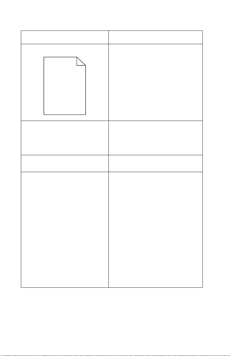
4048–00x
Problem Action
Pages ar e blank. • The print cartridge may be out of
toner or defec ti ve. Replace the
cartridge.
• You may have a sof tware er ror . Try
turning the printer off and bac k on.
• Check the photoconductor circuit
for contin uity.
• Check the printhead.
The operator panel li ghts do not
come on when the printer is
turned on .
The top cover does not close. Make sure the print cartridge is
The printer is on, but nothi ng
prints.
• The lights may ta ke a fe w seconds
to come on.
• Make sure the po we r cord is f irmly
plugged in at the back of the
printer and at the electrical outlet.
positioned correctly.
• Make sure the print cartridge is
installed properly.
• Make sure the parallel or USB
cable is firmly plugged into the
connector on the back of the
printer.
•Press Continue with a brief
button press to print a test page to
determine whether the probl em is
with the printer or the computer.
– If you can print a test
page, the problem is in
the computer or the
software appl ication.
– If you cannot print a t est
page, the problem is in
the printer.
2-58 Service Manual
Page 95

4048–00x
Problem Action
The media ske w s or buckle s. • Don’t overfill t ray 1 or the optional
tray 2 ( see med ia capac iti es in t he
media types and sizes table in the
User’s Guide).
• Make sur e the paper guides are
flush against the edges of the
media.
The paper sticks together/printer
feeds multiple sheets of paper.
The paper fai ls to f eed from tra y1. • Remov e t he paper from tr a y 1 an d
• Remove the paper from tray 1 or
the optional tray 2 and fan the
paper.
• Don’t overfill tray 1 or the optional
tray 2 ( see med ia capac iti es in t he
media types and s izes chart in t he
User’s Guide).
fan the paper.
• Make sur e tr ay 1 is selected from
the printer drive r.
• Do not overfill the tray.
Diagnostic Information 2-59
Page 96

4048–00x
Problem Action
The paper fail s to feed from the
optional tray 2.
• Make sure the option al tray 2 is
selected from the printe r dri ver.
• Remove the paper fr om the
optional tray 2 and fan the paper.
• Make sure the tray is pushed all
the way in.
• Make sure the metal pla te i s
pressed down before inserting it
into the printer.
Note: Once the tray is inserted,
the metal plate springs up so the
paper can feed into the printer.
2-60 Service Manual
• Make sure the paper does not
exceed the stack height indicator .
• Make sure the pa per is un der bot h
corner buckler s (see loading
paper in the User’s Guid e ).
Page 97

4048–00x
Problem Action
The Load Paper light is on even
though there is paper loaded in
the optional tray 2.
The printer does not print after a
paper jam has been cleared.
Unexpected characters print or
characters are missing.
• Make sur e the tray is pushed all
the way in.
• Press Continue.
• Press Continue or open and
close the printer cover to restart
the printer.
• Make sur e the pri nt cartridge is
installed properly.
• Make sur e you are using the
correct printer driver.
• Select hex trace mode to
determine what the problem is.
See “Configuration Menu
Group or Diagnostic Menu
Group” on page 3-2 for more
information.
• Restore factory defaults. See
“Restoring Factory Defaults”
on page 2-62 for more
information.
• Make sur e the parallel cable or
USB cable is firmly plugged in at
the back of the printer.
Jobs are not printing and the
Error light is on solid.
• Make sur e the pri nt cartridge is
installed properly.
• Make sur e the pri nter top cover is
closed.
• Make sur e the t op cover is
activati ng th e swit ch.
Diagnostic Information 2-61
Page 98

4048–00x
Restoring Factory Defaults
Sometimes resetting the printer to the original factory default
settings solves formatting problems.
1. Enter the configuration mode. See “Configuration Menu
Grou p or Diagnost i c Menu Group” on page 3-2 for mo r e
information.
2. Press and release Cancel.
The Ready/Data light is on.
3. Press Continue until lights flash.
The factory defaults are reset.
4. To return the printer online, POR the printer.
Using Print Quality Test Pages
To help isolate print quality problems, like streaking, print test pages
using the print quality test pages setting:
1. Enter the special function menu. See “Configuration Menu
Grou p or Diagnost i c Menu Group” on page 3-2 for mo r e
information.
2. Press Cancel and wait for the Ready/Data light.
3. Press Cancel again and wait for the Tone r Low light.
4. Press Cancel again and wait for both Ready/Data and Toner
Low lights.
5. Press and hold Continue until lig h ts cycl e.
Three pages print to help you evaluate print quality. The first
page has registration marks, the second page is gray, and the
third page is black. Once the paper exits into the output bin, the
printer r e tu rns t o the Ready state.
6. Use the test pages to isolate problems such as print too light,
toner streaks, and so on. See the Trou bleshooting tables in the
User’s Guide for solutions to these problems.
7. To return the printer online, POR the printer.
2-62 Service Manual
Page 99

4048–00x
3. Diagnostic Aids
Operator Panel
Menu De finition
The operator panel settings and operations are divided in two menu
groups.
Configuration Menu Group The Configura tion Men u gr oup cont ains a se t
Diagnostic Menu Group The Diagnostic Menu group contains the
The top four lights are on (home state) when the printer is in either
Configuration or Diagnostic mode. The only items that can be
changed have one or both Error and Continue lights on.
of menus, settings , and operations which are
infrequent ly r equir ed by a us er . Ge neral ly, the
options made availab le in this menu group
are used to configu re a printer for operation.
Access to the Configuration Menu gr oup is
gained by way of a POR key sequence. See
“Power–On Operations” on page 2-25 for
more information.
settings and oper ations used while
manufacturing and servicing the printer. See
“Power–On Operations” on page 2-25 for
more information.
• Press and release Cancel to advance through the menus.
• Press and release Continue to advance through the values for
a menu item until you find the one you want.
• Press and hold Continue until all lights cycle to save the value
for a menu item.
• Press and hold Cancel until all li g hts cycle to go to the home
state.
Diagnostic Aids 3-1
Page 100

4048–00x
Configuratio n Menu Group or Diagnostic Menu Group
Correct entry of either mode is indicated with the four top lights on.
Press and hold Continue (about 4 seconds) for the printer to
produce a page similar to the ones on page 3-4 and page 3-5,
depending on which mode is entered.
Note: For information on how to enter the configuration or
diagnostic modes, see “Power–On Operations” on page 2-25.
Moving Aroun d t he Menu
Referring to page 3-4 and page 3-5, menu items are designated by
the non–indented items listed along the left edge of the page.
(Bottom as printed from printer.)
Note: These items are un–shaded and have the four light pattern
indications printed.
• Press and release Cancel to move sequentially from one of the
menu items to another.
• Press and hold Cancel to jump to home state (top four lights
on).
• Press and release Continue to move through the values of the
item with values.
This action rotates only through the possible values of the
selected menu item.
Note:
– Menu items with values have either (or both) the Error or
Press Continue lights on.
– Menu items without values have neither Error nor Press
Continue lights on.
3-2 S er v ice M anual
 Loading...