

Page 1

Lexmark OptraTM T
• Table of Contents
• Start Diagnostics
• Safety and Notices
• Trademarks
4069-XXX
•Index
• Manuals Menu
Lexmark and Optra are trademarks of
Lexmark International , Inc ., regi st ered
in the United States and/or other
countries.
Page 2

4069-XXX
Edition: March 2001
The following paragraph does not apply to any country where such provisions are
inconsiste nt with local law: LEXMARK INTERNATIONAL, INC. PROV IDES THIS
PUBLICATION “AS IS” WITHOUT WARRANTY OF ANY KIND, EITHER EXPRE SS OR
IMPLIED , INCLUDING, BUT NOT LIMITED TO, THE IMPLIED WARRANTIES OF
MERCHANTABILITY OR FITNESS FOR A PARTICULAR PURPOSE. Some states do
not allow disclaimer of express or implied warranties in certain transactions; therefore,
this statement may not apply to you.
This publication could include technical inaccuracies or typographical errors. Changes
are periodically made to the information herein; these changes will be incorporated in
later editions. Improvements or changes in the products or the programs described may
be made at any time.
Comments may be addressed to Lexmark International, Inc., Department D22A/032-2,
740 West New Circle Road, Lexington, Kentucky 40550, U.S.A or e-mail at
ServiceInfoAndTraining@Lexmark.com. Lexmark may use or distribute any of the
information you supply in any way it believes appropriate without incurring any obligation
to you. You can purchase additional copies of publications related to this product by
calling 1-800-553-9727. In other countries, contact your point of purchase.
Lexmark and Optra are trademarks of Lexmark International, Inc., registered in the United
States and/or other countries.
Other trademarks are the property of their respective owners.
© Copyright Lexmark International, Inc. 1999, 2001.
All rights reserved.
UNITED STA TES GOVERNMENT RESTRICTED RIGHTS
This software and documentation are provided with RESTRICTED RIGHTS. Use,
duplication or disclosure by the Government is subject to restrictions as set forth in
subparagraph (c)(1)(ii) of the Rights in Technical Data and Computer Software clause at
DF ARS 252.227-7013 and in applicable FAR provisions: Lexmark International, Inc.,
Lexington, KY 40550.
P/N: 12G3794
Page 3

4069-XXX
Contents
Notices and Safety Information. . . . . . . . . . . . . . . . . . . . . . .ix
Laser Notices. . . . . . . . . . . . . . . . . . . . . . . . . . . . . . . . . . . . . . . ix
Safety Information . . . . . . . . . . . . . . . . . . . . . . . . . . . . . . . . . . xvii
Preface. . . . . . . . . . . . . . . . . . . . . . . . . . . . . . . . . . . . . . . . . . . . . xxii
General Information . . . . . . . . . . . . . . . . . . . . . . . . . . . . . . . . . . . 1-1
Options . . . . . . . . . . . . . . . . . . . . . . . . . . . . . . . . . . . . . . . . . . 1-3
Maintenance Approach . . . . . . . . . . . . . . . . . . . . . . . . . . . . . . 1-4
Tools Required For Service. . . . . . . . . . . . . . . . . . . . . . . . . . . 1-4
Acronyms. . . . . . . . . . . . . . . . . . . . . . . . . . . . . . . . . . . . . . . . . 1-5
Diagnostic Information. . . . . . . . . . . . . . . . . . . . . . . . . . . . . . . . . 2-1
Start. . . . . . . . . . . . . . . . . . . . . . . . . . . . . . . . . . . . . . . . . . . . . 2-1
Service Error Codes . . . . . . . . . . . . . . . . . . . . . . . . . . . . . . 2-2
User Status Messages . . . . . . . . . . . . . . . . . . . . . . . . . . 2-12
User Error Messages . . . . . . . . . . . . . . . . . . . . . . . . . . . . 2-16
Power-On Self Test (POST). . . . . . . . . . . . . . . . . . . . . . . 2-24
Symptom Tables. . . . . . . . . . . . . . . . . . . . . . . . . . . . . . . . 2-25
Service Checks . . . . . . . . . . . . . . . . . . . . . . . . . . . . . . . . . . . 2-28
Charge Roll Service Check . . . . . . . . . . . . . . . . . . . . . . . 2-29
Cover Open Switch/Cable Service Check . . . . . . . . . . . . 2-31
Dead Machine Service Check . . . . . . . . . . . . . . . . . . . . . 2-32
Duplex Option Service Check. . . . . . . . . . . . . . . . . . . . . . 2-35
Envelope Feeder Option Service Check . . . . . . . . . . . . . 2-38
Erase Lamp Service Check (010/212/414/616) . . . . . . . . 2-45
Fan Service Check . . . . . . . . . . . . . . . . . . . . . . . . . . . . . . 2-46
Fuser Service Check . . . . . . . . . . . . . . . . . . . . . . . . . . . . 2-47
Fuser Solenoid Service Check. . . . . . . . . . . . . . . . . . . . . 2-50
Input Sensor Service Check. . . . . . . . . . . . . . . . . . . . . . . 2-51
Input Tray(s) Option Service Check . . . . . . . . . . . . . . . . . 2-51
High Capacity Feeder Input Tray Service Check . . . . . . . 2-55
Main Drive Service Check . . . . . . . . . . . . . . . . . . . . . . . . 2-68
Operator Panel Service Check. . . . . . . . . . . . . . . . . . . . . 2-69
Options Service Check. . . . . . . . . . . . . . . . . . . . . . . . . . . 2-71
Output Bin Sensor Standard Tray Service Check . . . . . . 2-73
Output Expander Service Check . . . . . . . . . . . . . . . . . . . 2-74
High-Capacity Output Stacker Service Check . . . . . . . . . 2-79
5-Bin Mailbox Service Check . . . . . . . . . . . . . . . . . . . . . . 2-82
Paper Feed Service Check. . . . . . . . . . . . . . . . . . . . . . . . 2-88
Parallel Port Service Check . . . . . . . . . . . . . . . . . . . . . . . 2-90
Contents iii
Page 4

4069-XXX
Printhead Service Check. . . . . . . . . . . . . . . . . . . . . . . . . 2-91
Print Quality Service Check. . . . . . . . . . . . . . . . . . . . . . . 2-92
Smart Cartridge Service Check. . . . . . . . . . . . . . . . . . . 2-105
Serial Port Service Check . . . . . . . . . . . . . . . . . . . . . . . 2-106
Toner Sensor Service Check. . . . . . . . . . . . . . . . . . . . . 2-106
Transfer Roll Service Check . . . . . . . . . . . . . . . . . . . . . 2-107
Diagnostic Aids . . . . . . . . . . . . . . . . . . . . . . . . . . . . . . . . . . . . . . 3-1
Diagnostic Mode . . . . . . . . . . . . . . . . . . . . . . . . . . . . . . . . . . . 3-1
Device Tests. . . . . . . . . . . . . . . . . . . . . . . . . . . . . . . . . . . . . . 3-2
Quick Disk Test . . . . . . . . . . . . . . . . . . . . . . . . . . . . . . . . . 3-2
Disk Test/Clean . . . . . . . . . . . . . . . . . . . . . . . . . . . . . . . . . 3-2
Flash Test . . . . . . . . . . . . . . . . . . . . . . . . . . . . . . . . . . . . . 3-3
Disabling Download Emulations . . . . . . . . . . . . . . . . . . . . 3-3
Duplex Tests. . . . . . . . . . . . . . . . . . . . . . . . . . . . . . . . . . . . . . 3-4
Duplex Quick Test . . . . . . . . . . . . . . . . . . . . . . . . . . . . . . . 3-4
Duplex Sensor Test . . . . . . . . . . . . . . . . . . . . . . . . . . . . . . 3-5
Duplex Motor Test . . . . . . . . . . . . . . . . . . . . . . . . . . . . . . . 3-5
Duplex Feed 1 Test . . . . . . . . . . . . . . . . . . . . . . . . . . . . . . 3-7
Duplex Feed 2 Test . . . . . . . . . . . . . . . . . . . . . . . . . . . . . . 3-7
Error Log. . . . . . . . . . . . . . . . . . . . . . . . . . . . . . . . . . . . . . . . . 3-8
Viewing the Error Log . . . . . . . . . . . . . . . . . . . . . . . . . . . . 3-8
Clearing the Error Log . . . . . . . . . . . . . . . . . . . . . . . . . . . . 3-8
Hardware Tests. . . . . . . . . . . . . . . . . . . . . . . . . . . . . . . . . . . . 3-9
LCD Test . . . . . . . . . . . . . . . . . . . . . . . . . . . . . . . . . . . . . . 3-9
Button Test . . . . . . . . . . . . . . . . . . . . . . . . . . . . . . . . . . . . 3-9
SDRAM Memory Test . . . . . . . . . . . . . . . . . . . . . . . . . . . 3-10
ROM Memory Test . . . . . . . . . . . . . . . . . . . . . . . . . . . . . 3-10
Parallel Wrap Test . . . . . . . . . . . . . . . . . . . . . . . . . . . . . . 3-11
Serial Wrap Test . . . . . . . . . . . . . . . . . . . . . . . . . . . . . . . 3-12
Input Tray Tests . . . . . . . . . . . . . . . . . . . . . . . . . . . . . . . . . . 3-14
Input Tray Feed Test . . . . . . . . . . . . . . . . . . . . . . . . . . . . 3-14
Input Tray Sensor Test . . . . . . . . . . . . . . . . . . . . . . . . . . 3-14
Output Bin Test - Standard Bin . . . . . . . . . . . . . . . . . . . . 3-15
Output Bin Feed Test. . . . . . . . . . . . . . . . . . . . . . . . . . . . 3-15
Output Bin Sensor Test . . . . . . . . . . . . . . . . . . . . . . . . . . 3-16
Output Bin X Sensor Test . . . . . . . . . . . . . . . . . . . . . . . . 3-16
Base Sensor Test . . . . . . . . . . . . . . . . . . . . . . . . . . . . . . 3-17
5-Bin Mailbox Diverter Test . . . . . . . . . . . . . . . . . . . . . . . 3-18
Print Registration . . . . . . . . . . . . . . . . . . . . . . . . . . . . . . . . . 3-19
Printer Setup. . . . . . . . . . . . . . . . . . . . . . . . . . . . . . . . . . . . . 3-20
Setting the Page Count . . . . . . . . . . . . . . . . . . . . . . . . . . 3-20
Viewing the Permanent Page Count . . . . . . . . . . . . . . . . 3-20
iv Service Manual
Page 5

4069-XXX
Maintenance Page Count. . . . . . . . . . . . . . . . . . . . . . . . . 3-21
Setting Configuration ID . . . . . . . . . . . . . . . . . . . . . . . . . . 3-21
Restore EP Factory Defaults . . . . . . . . . . . . . . . . . . . . . . 3-22
Print Tests . . . . . . . . . . . . . . . . . . . . . . . . . . . . . . . . . . . . . . . 3-23
Print Quality Test Pages. . . . . . . . . . . . . . . . . . . . . . . . . . 3-24
Print Test with RIP (Controller Board) Removed . . . . . . . 3-25
Printing Menu Settings Page . . . . . . . . . . . . . . . . . . . . . . 3-26
Autocompensator Operation . . . . . . . . . . . . . . . . . . . . . . . . . 3-26
Autoconnect System, Paper Tray Options, Envelope Feeder and
Output Expander Operations. . . . . . . . . . . . . . . . . . . . . . . . . 3-27
Fuser Operation. . . . . . . . . . . . . . . . . . . . . . . . . . . . . . . . . . . 3-29
Paper Feed Jams . . . . . . . . . . . . . . . . . . . . . . . . . . . . . . . . . 3-30
Repair Information . . . . . . . . . . . . . . . . . . . . . . . . . . . . . . . . . . . . 4-1
Handling ESD-Sensitive Parts. . . . . . . . . . . . . . . . . . . . . . . . . 4-1
Adjustment Procedures . . . . . . . . . . . . . . . . . . . . . . . . . . . . . . 4-2
Duplex Motor Drive Belts . . . . . . . . . . . . . . . . . . . . . . . . . . 4-2
Fuser Solenoid Adjustment . . . . . . . . . . . . . . . . . . . . . . . . 4-3
Gap Adjustment . . . . . . . . . . . . . . . . . . . . . . . . . . . . . . . . . 4-3
Printhead Assembly Adjustment. . . . . . . . . . . . . . . . . . . . . 4-4
Paper Alignment Assembly Adjustment . . . . . . . . . . . . . . . 4-5
Screw Identification Table . . . . . . . . . . . . . . . . . . . . . . . . . . . . 4-7
Removal Procedures . . . . . . . . . . . . . . . . . . . . . . . . . . . . . . . 4-12
Covers . . . . . . . . . . . . . . . . . . . . . . . . . . . . . . . . . . . . . . . 4-12
Center Pan Assembly. . . . . . . . . . . . . . . . . . . . . . . . . . . . 4-16
Controller Board . . . . . . . . . . . . . . . . . . . . . . . . . . . . . . . . 4-17
Developer Drive Assembly. . . . . . . . . . . . . . . . . . . . . . . . 4-18
Duplex Board . . . . . . . . . . . . . . . . . . . . . . . . . . . . . . . . . . 4-19
Duplex Front Cover Assembly . . . . . . . . . . . . . . . . . . . . . 4-19
Duplex Front Cover Door . . . . . . . . . . . . . . . . . . . . . . . . . 4-19
Duplex Motor . . . . . . . . . . . . . . . . . . . . . . . . . . . . . . . . . . 4-20
EMC Shields. . . . . . . . . . . . . . . . . . . . . . . . . . . . . . . . . . . 4-21
Engine Board . . . . . . . . . . . . . . . . . . . . . . . . . . . . . . . . . . 4-23
Fans . . . . . . . . . . . . . . . . . . . . . . . . . . . . . . . . . . . . . . . . . 4-24
Frames . . . . . . . . . . . . . . . . . . . . . . . . . . . . . . . . . . . . . . . 4-26
Fuser . . . . . . . . . . . . . . . . . . . . . . . . . . . . . . . . . . . . . . . . 4-29
Fuser Board . . . . . . . . . . . . . . . . . . . . . . . . . . . . . . . . . . . 4-30
Fuser Cover . . . . . . . . . . . . . . . . . . . . . . . . . . . . . . . . . . . 4-31
Fuser Detack Fingers . . . . . . . . . . . . . . . . . . . . . . . . . . . . 4-31
Fuser Detack Housing Assembly . . . . . . . . . . . . . . . . . . . 4-32
Fuser Transfer Plate. . . . . . . . . . . . . . . . . . . . . . . . . . . . . 4-33
Fuser Envelope Conditioner Solenoid . . . . . . . . . . . . . . . 4-34
Fuser Narrow Media Sensor/Flag Assembly . . . . . . . . . . 4-35
Contents v
Page 6

4069-XXX
Fuser Exit Sensor Flag Assembly . . . . . . . . . . . . . . . . . . 4-35
Fuser Lamp . . . . . . . . . . . . . . . . . . . . . . . . . . . . . . . . . . . 4-35
Fuser Lower Exit Guide Assembly. . . . . . . . . . . . . . . . . . 4-36
High Voltage Power Supply. . . . . . . . . . . . . . . . . . . . . . . 4-37
Integrated Tray Compensator Assembly . . . . . . . . . . . . . 4-38
Integrated Tray Compensator Pick Roll Assembly . . . . . 4-39
Interconnect Board Assembly . . . . . . . . . . . . . . . . . . . . . 4-40
Low Voltage Power Supply . . . . . . . . . . . . . . . . . . . . . . . 4-42
Main Drive Assembly. . . . . . . . . . . . . . . . . . . . . . . . . . . . 4-43
Main Drive Motor . . . . . . . . . . . . . . . . . . . . . . . . . . . . . . . 4-45
Multipurpose Tray/Lower Deflector Assembly . . . . . . . . . 4-46
Operator Panel Assembly . . . . . . . . . . . . . . . . . . . . . . . . 4-48
Operator Panel Cable/Cover Open Switch Assembly . . . 4-49
Optional 250/500 Paper Tray Assembly . . . . . . . . . . . . . 4-50
Paper Alignment Assembly . . . . . . . . . . . . . . . . . . . . . . . 4-51
Paper Deflectors . . . . . . . . . . . . . . . . . . . . . . . . . . . . . . . 4-53
Paper Input Sensor . . . . . . . . . . . . . . . . . . . . . . . . . . . . . 4-54
Paper Size Sensing Board. . . . . . . . . . . . . . . . . . . . . . . . 4-54
Pick Roll. . . . . . . . . . . . . . . . . . . . . . . . . . . . . . . . . . . . . . 4-55
Printhead . . . . . . . . . . . . . . . . . . . . . . . . . . . . . . . . . . . . . 4-56
Redrive Assembly . . . . . . . . . . . . . . . . . . . . . . . . . . . . . . 4-57
Smart Cartridge Contacts . . . . . . . . . . . . . . . . . . . . . . . . 4-58
Toner Sensor. . . . . . . . . . . . . . . . . . . . . . . . . . . . . . . . . . 4-59
Transfer Roll Assembly . . . . . . . . . . . . . . . . . . . . . . . . . . 4-60
Upper Paper Deflector Assembly . . . . . . . . . . . . . . . . . . 4-60
Upper Front Cover Hinge Assembly . . . . . . . . . . . . . . . . 4-61
Upper Front Cover Interlock Switch Assembly . . . . . . . . 4-62
Connector Locations . . . . . . . . . . . . . . . . . . . . . . . . . . . . . . . . . . 5-1
Low Voltage Power Supply . . . . . . . . . . . . . . . . . . . . . . . . 5-1
High Voltage Power Supply. . . . . . . . . . . . . . . . . . . . . . . . 5-3
Engine Board. . . . . . . . . . . . . . . . . . . . . . . . . . . . . . . . . . . 5-4
Fuser Board. . . . . . . . . . . . . . . . . . . . . . . . . . . . . . . . . . . 5-11
Interconnect Board . . . . . . . . . . . . . . . . . . . . . . . . . . . . . 5-12
Envelope Option Board . . . . . . . . . . . . . . . . . . . . . . . . . . 5-15
Duplex Option Board . . . . . . . . . . . . . . . . . . . . . . . . . . . . 5-17
Autoconnect - Top . . . . . . . . . . . . . . . . . . . . . . . . . . . . . . 5-19
Output Expander Control Board . . . . . . . . . . . . . . . . . . . 5-20
High-Capacity Output Stacker Board. . . . . . . . . . . . . . . . 5-22
Preventive Maintenance. . . . . . . . . . . . . . . . . . . . . . . . . . . . . . . . 6-1
Safety Inspection Guide . . . . . . . . . . . . . . . . . . . . . . . . . . . . . 6-1
Lubrication Specifications. . . . . . . . . . . . . . . . . . . . . . . . . . . . 6-1
Scheduled Maintenance . . . . . . . . . . . . . . . . . . . . . . . . . . . . 6-2
vi Service Manual
Page 7

4069-XXX
Parts Catalog . . . . . . . . . . . . . . . . . . . . . . . . . . . . . . . . . . . . . . . . . 7-1
How To Use This Parts Catalog . . . . . . . . . . . . . . . . . . . . . . . 7-1
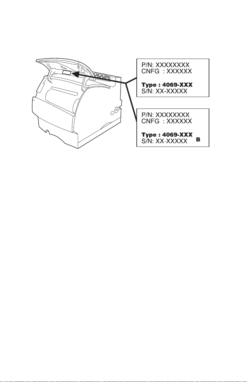
Printer Serial Label. . . . . . . . . . . . . . . . . . . . . . . . . . . . . . . 7-2
Assembly 1: Covers . . . . . . . . . . . . . . . . . . . . . . . . . . . . . . 7-4
Assembly 2: Frame. . . . . . . . . . . . . . . . . . . . . . . . . . . . . . . 7-8
Assembly 3: Printhead . . . . . . . . . . . . . . . . . . . . . . . . . . . 7-12
Assembly 4: Paper Feed (Autocompensator). . . . . . . . . . 7-14
Assembly 5: Paper Feed - Multipurpose Unit. . . . . . . . . . 7-16
Assembly 6: Paper Feed - Alignment. . . . . . . . . . . . . . . . 7-18
Assembly 7: Paper Feed - Output . . . . . . . . . . . . . . . . . . 7-20
Assembly 8: Integrated Paper Tray - 250 Sheet . . . . . . . 7-22
Assembly 9: Integrated Paper Tray - 500 Sheet . . . . . . . 7-24
Assembly 10: Main Drive . . . . . . . . . . . . . . . . . . . . . . . . . 7-26
Assembly 11: Developer Drive. . . . . . . . . . . . . . . . . . . . . 7-28
Assembly 12: Hot Roll Fuser . . . . . . . . . . . . . . . . . . . . . . 7-30
Assembly 13: Transfer . . . . . . . . . . . . . . . . . . . . . . . . . . . 7-34
Assembly 14: Charging . . . . . . . . . . . . . . . . . . . . . . . . . . 7-36
Assembly 15: Electronics . . . . . . . . . . . . . . . . . . . . . . . . . 7-38
Assembly 16: 250 Sheet Tray . . . . . . . . . . . . . . . . . . . . . 7-52
Assembly 17: 500 Sheet Tray . . . . . . . . . . . . . . . . . . . . . 7-58
Assembly 18: Duplex . . . . . . . . . . . . . . . . . . . . . . . . . . . . 7-62
Assembly 19: Output Expander . . . . . . . . . . . . . . . . . . . . 7-68
Assembly 20: Envelope Feeder . . . . . . . . . . . . . . . . . . . . 7-72
Assembly 21: High Capacity Feeder . . . . . . . . . . . . . . . . 7-76
Assembly 22: Kiosk - Vertical Paper Adapter. . . . . . . . . . 7-90
Assembly 23: Kiosk - Horizontal Paper Adapter. . . . . . . . 7-92
Assembly 24: High-Capacity Output Stacker . . . . . . . . . . 7-94
Assembly 25: 5-Bin Mailbox. . . . . . . . . . . . . . . . . . . . . . 7-100
Assembly 26: Options . . . . . . . . . . . . . . . . . . . . . . . . . . 7-104
Assembly 27: Miscellaneous . . . . . . . . . . . . . . . . . . . . . 7-106
Index. . . . . . . . . . . . . . . . . . . . . . . . . . . . . . . . . . . . . . . . . . . . . . . . I-1
Contents vii
Page 8

4069-XXX
viii Service Manual
Page 9
4069-XXX
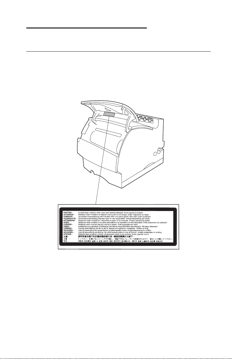
Notices and Safety Information
Laser Notices
The following laser notice labels may be affixed to this printer as
shown:
Laser Advisory Label
Notices and Safety Information ix
Page 10
4069-XXX
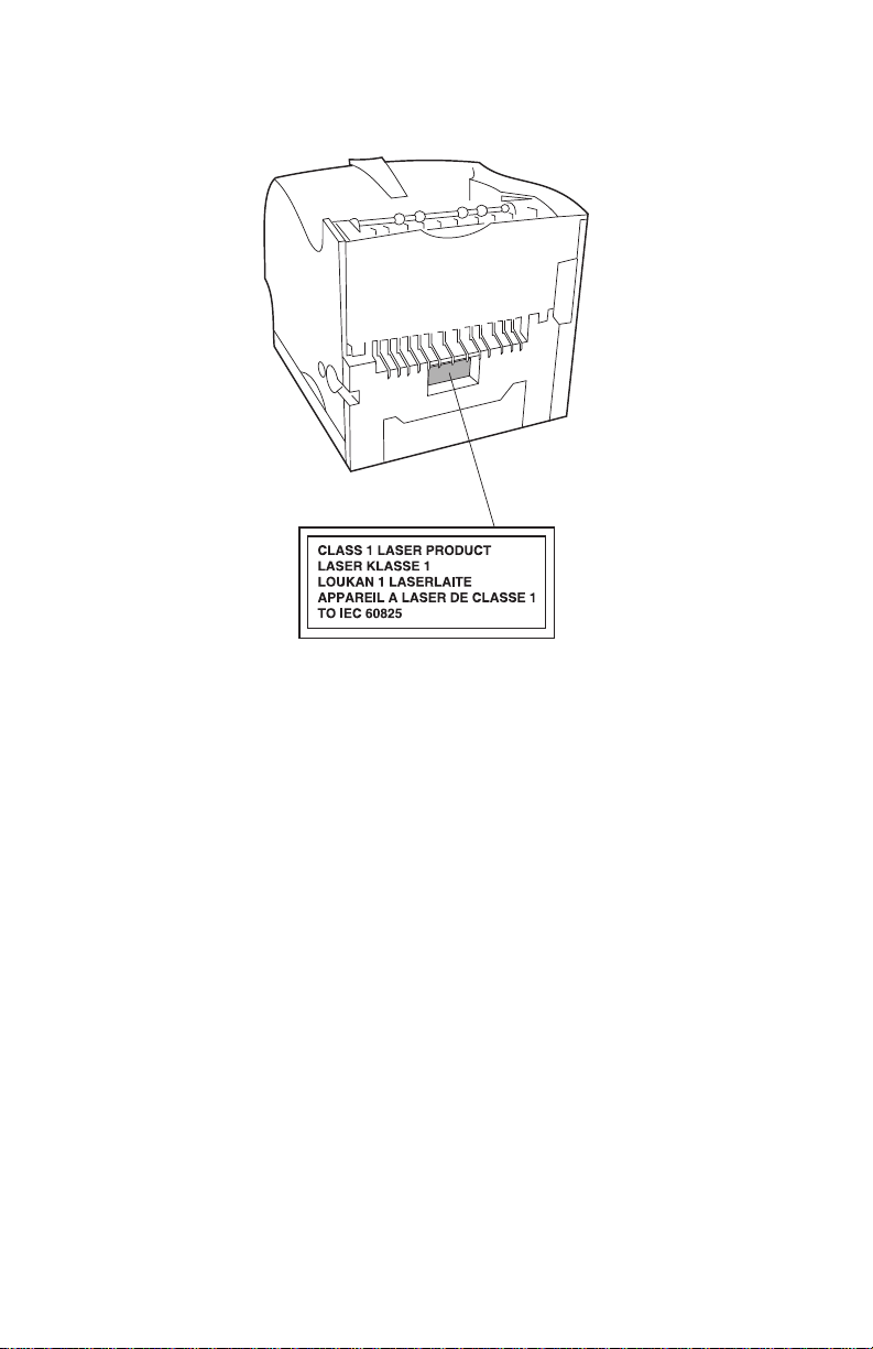
Class 1 Laser Statement Label
x Service Manual
Page 11

4069-XXX
Laser Notice
The printer is certified in the U.S. to conform to the requirements of
DHHS 21 CFR Subchapter J for Class I (1) laser products, and
elsewhere is certified as a Class I laser product conforming to the
requirements of IEC 60825.
Class I laser products are not considered to be hazardous. The
printer contains internally a Class IIIb (3b) laser that is nominally a 5
milliwatt gallium arsenide laser operating in the wavelength region of
770-795 nanometers. The laser system and printer are designed so
there is never any human access to laser radiation above a Class I
level during normal operation, user maintenance, or prescribed
service condition.
Laser
Der Drucker erfüllt gemäß amtlicher Bestätigung der USA die
Anforderungen der Bestimmung DHHS (Department of Health and
Human Services) 21 CFR Teil J für Laserprodukte der Klasse I (1).
In anderen Ländern gilt der Drucker als Laserprodukt der Klasse I,
der die Anforderungen der IEC (International Electrotechnical
Commission) 60825 gemäß amtlicher Bestätigung erfüllt.
Laserprodukte der Klasse I gelten als unschädlich. Im Inneren des
Druckers befindet sich ein Laser der Klasse IIIb (3b), bei dem es
sich um einen Galliumarsenlaser mit 5 Milliwatt handelt, der Wellen
der Länge 770-795 Nanometer ausstrahlt. Das Lasersystem und der
Drucker sind so konzipiert, daß im Normalbetrieb, bei der Wartung
durch den Benutzer oder bei ordnungsgemäßer Wartung durch den
Kundendienst Laserbestrahlung, die die Klasse I übersteigen würde,
Menschen keinesfalls erreicht.
Avis relatif à l’utilisation de laser
Pour les Etats-Unis : cette imprimante est certifiée conforme aux
provisions DHHS 21 CFR alinéa J concernant les produits laser de
Classe I (1). Pour les autres pays : cette imprimante répo nd aux
normes IEC 60825 relatives aux produits laser de Classe I.
Notices and Safety Information xi
Page 12

4069-XXX
Les produits laser de Classe I sont considérés comme des produits
non dangereux. Cette imprimante est équipée d’un laser de Classe
IIIb (3b) (arséniure de gallium d’une puissance nominale de 5
milliwatts) émettant sur des longueurs d’onde comprises entre 770
et 795 nanomètres. L’imprimante et son système laser sont conçus
pour impossible, dans des conditions normales d’utilisation,
d’entretien par l’utilisateur ou de révision, l’exposition à des
rayonnements laser supérieurs à des ra yonnements de Classe I .
Avver tenze sui prodotti laser
Questa stampante è certificata negli Stati Uniti per essere conforme
ai requisiti del DHHS 21 CFR Sottocapitolo J per i prodotti laser di
classe 1 ed è certificata negli altri Paesi come prodotto laser di
classe 1 conforme ai requisiti della norma CEI 60825.
I prodotti laser di classe non sono considerati pericolosi. La
stampante contiene al suo interno un laser di classe IIIb (3b)
all’arseniuro di gallio della potenza di 5mW che opera sulla
lunghezza d’onda compresa tra 770 e 795 nanometri. Il sistema
laser e la stampante sono stati progettati in modo tale che le
persone a contatto con la stampante, durante il normale
funzionamento, le operazioni di servizio o quelle di assistenza
tecnica, non ricevano radiazioni laser superiori al livello della classe
1.
Avisos sobre el láser
Se certifica que, en los EE.UU., esta impresora cumple los
requisitos para los productos láser de Clase I (1) establecidos en el
subcapítulo J de la norma CFR 21 del DHHS (Departamento de
Sanidad y Servicios) y, en los demás países, reúne todas las
condiciones expuestas en la norma IEC 60825 para productos láser
de Clase I (1).
Los productos láser de Clase I no se consideran peligrosos. La
impresora contiene en su interior un láser de Clase IIIb (3b) de
arseniuro de galio de funcionamiento nominal a 5 milivatios en una
longitud de onda de 770 a 795 nanómetros. El sistema láser y la
impresora están diseñados de forma que ninguna persona pueda
verse afectada por ningún tipo de radiac ión láser superior al nivel de
xii Service Manual
Page 13

4069-XXX
la Clase I durante su uso normal, el mantenimiento realizado por el
usuario o cualquier otra situación de servicio técnico.
Declaração sobre Laser
A impressora está certificada nos E.U.A. em conformidade com os
requisitos da regulamen t ação DHHS 21 CFR Subcapítulo J para a
Classe I (1) de produtos laser. Em outros locais, está certificada
como um produto laser da Classe I, em conformidade com os
requisitos da norma IEC 60825.
Os produtos laser da Classe I não são considerados perigosos.
Internamente, a impressora contém um produto laser da Classe IIIb
(3b), designado laser de arseneto de potássio, de 5 milliwatts
,operando numa faixa de comprimento de onda entre 770 e 795
nanómetros. O sistema e a impressora laser foram concebidos de
forma a nunca existir qualquer possiblidade de acesso humano a
radiação laser superior a um nível de Classe I durante a operação
normal, a manutenção feita pelo utilizador ou condições de
assistência prescritas.
Laserinformatie
De printer voldoet aan de eisen die gesteld worden aan een
laserprodukt van klasse I. Voor de Verenigde Staten zijn deze eisen
vastgelegd in DHHS 21 CFR Subchapter J, voor andere landen in
IEC 60825.
Laserprodukten van klasse I worden niet als ongevaarlijk
aangemerkt. De printer is voorzien van een laser van klasse IIIb
(3b), dat wil zeggen een gallium arsenide-laser van 5 milliwatt met
een golflengte van 770-795 nanometer. Het lasergedeelte en de
printer zijn zo ontworpen dat bij normaal gebruik, bij onderhoud of
reparatie conform de voorschriften, nooit blootstelling mogelijk is
aan laserstraling boven een niveau zoals voorgeschreven is voor
klasse 1.
Notices and Safety Information xiii
Page 14

4069-XXX
Lasermeddelelse
Printeren er godkendt som et Klasse I-laserprodukt, i
overenstemmelse med kravene i IEC 60825.
Klasse I-laserprodukter betragtes ikke som farlige. Printeren
indeholder internt en Klasse IIIB (3b)-laser, der nominelt er en 5
milliwatt galliumarsenid laser, som arbejder på bølgelængdeområdet
770-795 nanometer. Lasersystemet og printeren er udformet
således, at mennesker aldrig udsættes for en laserstråling over
Klasse I-niveau ved normal drift, brugervedligeholdelse eller
obligatoriske servicebetingelser.
Huomautus laserlaitteesta
Tämä kirjoitin on Yhdysvalloissa luokan I (1) laserlaitteiden DHHS
21 CFR Subchapter J -määrityksen mukainen ja muualla luokan I
laserlaitteiden IEC 60825 -määrityksen mukainen.
Luokan I laserlaitteiden ei katsota olevan vaarallisia käyttäjälle.
Kirjoittimessa on sisäinen luokan IIIb (3b) 5 milliwatin
galliumarsenidilaser, joka toimii aaltoalueella 770 - 795 nanometriä.
Laserjärjestelmä ja kirjoitin on suunniteltu siten, että käyttäjä ei
altistu luokan I määrityksiä voimakkaammalle säteilylle kirjoittimen
normaalin toiminnan, käyttäjän tekemien huoltotoimien tai muide n
huoltotoimien yhteydessä.
VARO! Avattaessa ja suojalukitus ohitettaessa olet alttiina
näkymättömälle lasersäteilylle. Älä katso säteeseen.
VARNING! Osynlig laserstrålning när denna del är öppnad och
spärren är urkopplad. Betrakta ej strålen.
Laser-notis
Denna skrivare är i USA certifierad att motsvara kraven i DHHS 21
CFR, underparagraf J för laserprodukter av Klass I (1). I andra
länder uppfyller skrivaren kraven för laserprodukter av Klass I enligt
kraven i IEC 60825.
xiv Service Manual
Page 15

4069-XXX
Laserprodukter i Klass I anses ej hälsovådliga. Skrivaren har en
inbyggd laser av Klass IIIb (3b) som består av en laserenhet av
gallium-arsenid på 5 milliwatt som arbetar i våglängdsområdet 770795 nanometer. Lasersystemet och skrivaren är utformade så att det
aldrig finns risk för att någon person utsätts för lasers t r ålning över
Klass I-nivå vid normal användning, underhåll som utförs av
användaren eller annan föreskriven serviceåtgärd.
Laser-melding
Skriveren er godkjent i USA etter kravene i DHHS 21 CFR,
underkapittel J, for klasse I (1) laserprodukter, og er i andre land
godkjent som et Klasse I-laserprodukt i samsvar med kravene i IEC
60825.
Klasse I-laserprodukter er ikke å betrakte som farlige. Skriveren
inneholder internt en klasse IIIb (3b)-laser, som består av en
gallium-arsenlaserenhet som avgir stråling i bølgelengdeområdet
770-795 nanometer. Lasersystemet og skriveren er utformet slik at
personer aldri utsettes for laserstråling ut over klasse I-nivå under
vanlig bruk, vedlikehold som utføres av brukeren, eller foreskrevne
serviceoperasjoner.
Avís sobre el Làser
Segons ha estat certificat als Estats Units, aquesta impressora
compleix els requisits de DHHS 21 CFR, apartat J, pels productes
làser de classe I (1), i segons ha estat certificat en altres llocs, és un
producte làser de classe I que compleix els requisits d’IEC 60825.
Els productes làser de classe I no es consideren perillosos. Aquesta
impressora conté un làser de classe IIIb (3b) d’arseniür de gal.li,
nominalment de 5 mil.liwats, i funciona a la regió de longitud d’ona
de 770-795 nanòmet re s. El siste ma làser i la impressora han sigut
concebuts de manera que mai hi hagi exposició a la radiació làser
per sobre d’un nivell de classe I durant una operació normal, durant
les tasques de manteniment d’usuari ni durant els serveis que
satisfacin les condicions prescrites.
Notices and Safety Information xv
Page 16
4069-XXX
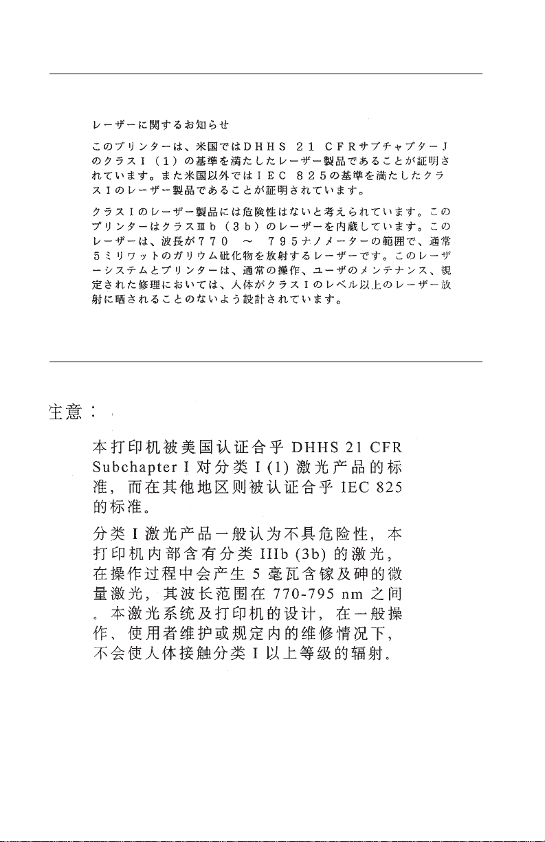
Japanese Laser Notice
Chinese Laser Notice
xvi Service Manual
Page 17
4069-XXX
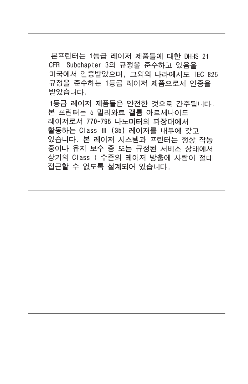
Korean Laser Notice
Safety Information
This product is designed, tested and approved to meet strict
•
global safety standards with the use of specific Lexmark
components. The safety features of some parts may not always
be obvious. Lexmark is not responsible for the use of other
replacement parts.
• The maintenance information for this product has been
prepared for use by a professional service person and is not
intended to be used by others.
• There may be an increased risk of electric shock and personal
injury during disassembly and servicing of this product.
Professional service personnel should understand this and take
necessar y pr ec autions.
Consignes de Sécurité
Ce produit a été conçu, testé et approuvé pour respecter les
•
normes strictes de sécurité globale lors de l'utilisation de
composants Lexmark sp écifiques. Les caractéristiques de
Notices and Safety Information xvii
Page 18

4069-XXX
sécurité de certains éléments ne sont pas toujours évidentes.
Lexmark ne peut être tenu responsable de l'utilisation d'autres
pièces de rechange.
• Les consignes d'entretien et de réparation de ce produit
s'adressent uniquement à un personnel de maintenance
qualifié.
• Le démontage et l'entretien de ce produit pouvant présenter
certains risques électriques, le personnel d'entretien qualifié
devra prendre toutes les précautions nécessaires.
Norme di sicurezza
Il prodotto è stato progettato, testato e approvato in conformità a
•
severi standard di sicurezza e per l’utilizzo con componenti
Lexmark specifici. Le caratteristiche di sicurezza di alcune parti
non sempre sono di immediata comprensione. Lexmark non è
responsabile per l’utilizzo di parti di ricambio di altri produttori.
• Le informazioni riguardanti la manutenzione di questo prodotto
sono indirizzate soltanto al personale di assistenza autorizzato.
• Durante lo smontaggio e la manutenzione di questo prodotto, il
rischio di subire scosse elettriche e danni alla persona è più
elevato. Il personale di assistenza autorizzato, deve, quindi,
adottare le precauzioni necessarie.
Sicherheitshinweise
Dieses Produkt und die zugehörigen Komponenten wurden
•
entworfen und getestet, um beim Einsatz die weltweit gültigen
Sicherheitsanforderungen zu erfüllen. Die sicherheitsrelevanten
Funktionen der Bauteile und Optionen sind nicht immer
offensichtlich. Sofern Teile eingesetzt werden, die nicht von
Lexmark sind, wird von Lexmark keinerlei Verantwortung oder
Haftung für dieses Produkt übernommen.
• Die Wartungsinformationen für dieses Produkt sind
ausschließlich für die Verwendung durch einen
Wartungsfachmann bestimmt.
• Während des Auseinandernehmens und der Wartung des
Geräts besteht ein zusätzliches Risiko eines elektrischen
Schlags und körperlicher Verletzung. Das zuständige
xviii Service Manual
Page 19

4069-XXX
Fachpersonal sollte entsprechende Vorsichtsmaßnahmen
treffen.
Pautas de Segurida d
Este producto se ha diseñado, verificado y aprobado para
•
cumplir los más estrictos estándares de seguridad global
usando los componentes específicos de Lexmark. Puede que
las características de seguridad de algunas piezas no sean
siempre evidentes. Lexmark no se hace responsable del uso de
otras piezas de recambio.
• La información sobre el mantenimiento de este producto está
dirigida exclusivamente al personal cualificado de
mantenimiento.
• Existe mayor riesgo de descarga eléctrica y de daños
personales durante el desmontaje y la reparación de la
máquina. El personal cualificado debe ser consciente de este
peligro y tomar las precauciones necesarias.
Informações de Segurança
Este produto foi concebido, testado e aprovado para satisfazer
•
os padrões globais de segurança na utilização de componentes
específicos da Lexmark. As funções de segurança de alguns
dos componentes podem não ser sempre óbvias. A Lexmark
não é responsável pela utiliza ção de outros componentes de
substituição.
• As informações de segurança relativas a este produto
destinam-se a profissio nai s destes serviços e não devem ser
utilizadas por outras pessoas.
• Risco de choques eléctricos e ferimentos graves durante a
desmontagem e manutenção deste produto. Os profissionais
destes serviços devem estar avisados deste facto e tomar os
cuidados necessários.
Notices and Safety Information xix
Page 20

4069-XXX
Informació de Seguretat
Aquest producte està dissenyat, comprovat i aprovat per tal
•
d'acomplir les estrictes normes de seguretat globals amb la
utililització de components específics de Lexmark. Les
característiques de seguretat d'algunes peces pot ser que no
sempre siguin òbvies. Lexmark no es responsabilitza de l'us
d'altres peces de recanvi.
• La informació pel manteniment d’aquest producte està
orientada exclusivament a professionals i no està destinada a
ningú que no ho sigui.
• El risc de xoc elèctric i de danys personals pot augmentar
durant el procés de desmuntatge i de serv e i d’aquest producte.
El personal professional ha d’estar-ne assabentat i prendre les
mesures convenients.
xx Service Manual
Page 21
4069-XXX
Chinese Safety Information
Korean Safety Information
Ozone Information
This product does not produce measurable amounts of ozone gas.
Notices and Safety Information xxi
Page 22

4069-XXX
Preface
This manual is divided into the following chapters:
• “General Information ” contains a general description of the
printer, options, and the maintenance approach used to repair it.
General environmental and safety instructions as well as
special tools and test equipment are listed in this chapter.
• “Diagnostic Information” contains a service error code table,
user status message table, user error message table, symptom
table, and service checks used to isolate failing field replaceable
units (FRUs).
• “Diagnostic Aids” contains tests and checks used to locate or
repeat symptoms of printer problems. Printer operation
information is provided to enhance the tests and checks.
• “Repair Information” provides instructions for making printer
adjustments and removing and installing FRUs.
• “Connector Locations” uses illustrations to identify the major
components and test points on the printer.
• “Preventive Maintenance” contains safety inspection guidelines,
lubrication specifications, and maintenance information to
prevent problems and maintain performance.
• “Parts Ca talog” contains illustrations and part numbers for
individual FRUs.
xxii Service Manual
Page 23

4069-XXX
1. General Informatio n
The Optra™ T laser printers are letter quality page printers designed
to attach to IBM-compatible PC’s and to most computer networks.
The Optra T laser printer is available in the following models.
Model Name Type
Optra T 610 4069-010
Optra T 610n 4069-01n
Optra T 612 4069-212
Optra T 612n 4069-21n
Optra T 614 4069-414
Optra T 614 4069-41b
Optra T 614n 4069-41e
Optra T 614nl 4069-41l
Optra T 614n 4069-41n
Optra T 616 4069-616
Optra T 616n 4069-61n
Optra T 23v 4069-23v
Optra T 23e 4069-23e
General Information 1-1
Page 24
4069-XXX
Look at the printer serial label to identify the printer you are working
on. There are two service levels of Optra T printers. Some printers
are at a service level B as indicated by the B on the label.
1-2 Service Manual
Page 25

4069-XXX
Options
The following options are available. Some options are not available
in every country. Contact y our point of purchase for options available
in your country.
Memory options of 4MB, 8MB, 16MB, 32MB, 64MB and 128MB
SDRAM DIMM
Flash memory options of 2MB, 4MB, 8MB and 16MB DIMM
Integrated network options
Token-Ring
Ethernet
Tri-Port Adapter
IR Adapter
IPDS SIMM
Prescribe SIM M
TIFF SIMM
Barcode SIMM
Parallel Inter face Card
SCS
USB/Parallel Port
Marknet Print Servers
250 and 500-sheet paper trays of A5, letter, and legal size.
250 Sheet Special Media Tray Assembly
500 Sheet Special Media Tray
2000 Sheet High Capacity Feeder
Envelope feeder
Duplex option - 250 Sheet
Duplex option - 500 Sheet
Hard Disk - 2.1 GB
Forms Hard Disk - 2.1 GB
Vertical Kiosk Presenter
Horizontal Kiosk Presenter
Output Expander
5-Bin Mailbox
High Capacity Output Stacker
General Information 1-3
Page 26

4069-XXX
Maintenance Approach
The diagnostic information in this manual leads you to the correct
field replaceable unit (FRU) or part. Use the service error codes,
user status messages, user error messages, service checks, and
diagnostic aids to determine the printer problem and repair the
failure. After you complete the repair, perform tests as needed to
verify the repair.
Tools Required For Ser vice
Flat-blade screwdriver
#1 Phillips screwdriver
#2 Phillips screwdriver
T10 Torx Screwdriver
7.0 mm nut driver
5.5 mm wrench
Needlenose pliers
Diagonal pliers
Spring hook
Feeler gauges
Analog or digital multimeter
Parallel wrap plug 1319128
Serial wrap plug 1329048
Twinax /s er i al debug cable 1381963
Coax/serial debug cable 1381964
1-4 Service Manual
Page 27

4069-XXX
Acronyms
CSU Customer Setup
DIMM Dual In-Line Memory Module
DRAM Dynamic Random Access Memory
EDO Enhanced Data Out
EP Electrophotographic Process
EPROM Erasable, Programmable Read-Only
Memory
ESD Electrostatic Discharge
FRU Field Replaceable Unit
GB Gigabyte
HVPS High Voltage Power Supply
LASER Light Amplification by Stimulated Emission
of Radiation
LCD Liquid Crystal Display
LED Light-Emitting Diode
LVPS Low Voltage Power Supply
MROM Masked Read Only Memory
NVRAM Nonvolatile Random Access Memory
OEM Original Equipment Manufacturer
PC Photoconductor
POR Power-On Reset
POST Power-On Self Test
RIP Raster Imaging Processor
ROM Read Only Memory
SIMM Single In-Line Memory Module
SDRAM Synchronous Dual Random Access
Memory
SRAM Static Random Access Memory
UPR Used Parts Return
V ac Volts alternating current
V dc Volts direct current
General Information 1-5
Page 28

4069-XXX
1-6 Service Manual
Page 29

4069-XXX
2. Diagnostic Information
Start
CAUTION: Remove the power cord from the printer or wall outlet
before you connect or disconnect any cable or electronic board or
assembly for personal safety and to prevent damage to the printer.
Use the handholds on the side of the printer. Make sure your fingers
are not under the printer when you lift or set the printer down.
Use the service error code, user status message, user error
message, symptom table, service checks, and diagnostic aids in this
chapter to determine the corrective action necessary to repair a
malfunctioning printer.
Service error codes are indicated by a three-digit error code. If a
service error code is displayed, go to the
page 2-2
.
User status messages provide the user with information on the
current status of the printer. Ready is displayed on the first line of the
display unless Power Saver is invoked, and then Power Saver is
displayed. If a user status message is displayed, go to the
Status Messages” on page 2-12
.
“Service Error Codes” on
“User
User error messages are indicated by a two or three-digit error code
that provides the user with information that explains a problem with a
print cartridge, paper jam, option, port, and so on. If a user error
message is displayed, go to the
If your machine completes the
page 2-24
“Symptom Tables” on page 2-25. Locate your symptom and take the
without an error, and you have a symptom, go to the
“User Error Messages” on page2-16.
“Power-On Self Test (POST)” on
appropriate action.
If a service error code appears while you are working on the
machine, go to the
“Service Error Codes” on page 2-2 and take the
indicated action for that error.
Diagnostic Information 2-1
Page 30

4069-XXX
Service Error Codes
Service Error Codes are generally non-recoverable except in an
intermittent cond iti on when you can POR the prin ter to temporar i ly
recover from the error condition.
Error Code Action
900 RIP Software Contact the next support level or call Lexmark.
901 Engine Flash Indicates that the flash which the engine board code is
programmed into is bad. Replace the engine board.
902 General
Engine Software
903 Paperport
Link Driver Error
904 Interface
Violation by the
controller
software
905 Interface
Violation by
Paperport Device
906 ControllerEngine Link
Driver Error
910 DC Pick
Motor DC Pick
Motor Stall
911 DC Pick
Motor Excessive
PWM
912 DC pick
motor below
speed
These errors indicate an unrecoverable engine software
error. Replace the engine board.
Check for correct location of the jumpers on the
interconnect board for the model/type printer you are
servicing. Incorrect jumper settings can cause a 902
service error. If jumpers are set correctly, replace the
engine board.
Error Codes 910,911,912,913 and 914 are indications
that a Tray 1 paper feed problem has been detec ted. Go
to the “Input Tray(s) Option Service Check” on
page 2-51.
913 DC pick
motor over speed
2-2 Service Manual
Page 31

4069-XXX
Error Code A ction
914 DC pick
motor: No
encoder feedback
917 Transfer Roll Indicates a problem in the transfer roll area. Go to the
920 Fuser Error Indicates that the fuser is below temperature when
921 Fuser Error Indicates that the fuser is below standby temperature
922 Fuser Error Fuser failed to reach standby temperature. Go to the
923 Fuser Error Fuser is too hot during printing or when printer is idle . Go
924 Fuser Error An open circuit has been detected in the Fuser
925 Fuser Error Wrong fuser lamp installed. Check the fuser la mp f or the
Check the integr ated pa per tray (tray 1) for correct paper
loading. Reload the paper and POR the printer. If the
error continues, go to the “Input Tray(s) Option Service
Check” on page 2-51.
“Transfer Roll Service Check” on page 2-107.
Note: This error also displays if an incorrect level HVPS
assembly is insta lled in a printer tha t has the er ase lam p
assembly installed. Check to make sure the correct
HVPS assem bly is installed.
printing. Go to the “Fu ser Service Chec k” on pag e 2-47. .
when the printer is idle. Go to the “Fuser Service Chec k ”
on page 2-47.
“Fuser Service Check” on page2-47.
to the “Fuser Service Check” on page 2-47.
Thermistor Circuit. Go to the “Fuser Service Check” on
page 2-47.
correct type of lamp that should be installed.
If the correct lamp has be en instal led and y ou still hav e a
925 error, the following may be the cause:
1. The fuser may have reached stand by temper ature too
quickly.
2. Check too make sure the correct hot roll has been
installed.
3. Check the line voltage to make sure it is not above the
maximum rating for the printer.
927 Fan Stalled Indicates a printer fan stalled. Go to the “Fan Service
Check” on page 2-46.
Diagnostic Information 2-3
Page 32

4069-XXX
Error Code Action
928 Erase Lamps Models 010/212/414/616
929 T one r Sensor The toner sensor is n ot operat ing properly, the devel oper
930 Printhead
Error
931-935
Printhead Error
932 - Printhead:
Lost Hsync
933 - Mirror Motor
Locks/Lost Hsync
934 - Mirror Motor
Lost Lock
Indicates that the engine has detected that either the
erase lamp assemb l y is mi ss ing or disco nne cted. Go to
the “Erase Lamp Service Check (010/212/414/616)” on
page 2-45.
Models 41b/41e/41l and models 010/212/414/616 at
service level B do not have erase lamps installed. Go to
“Printer Serial Label” on page 7-2 to identify the printer
service level. Check to make sure the correct HVPS is
installed if this error displays on these models.
drive assembly is not operating properly or the print
cartridge is defective. Go to the “Toner Sensor Service
Check” on page2-106.
The wrong printhead is installed. Replace with the
correct printhead.
These errors represe nt a p rob lem with the p rinthead. G o
to the “Printhead Service Check” on page 2-91.
935 - Mirror Motor
unable to reach
operating speed.
936-937
Transport Motor
936 - Main Drive
Motor initial lock
failure
937 - Main Drive
Motor lost lock
2-4 Service Manual
Indicates a problem with the mai n drive motor. Go to the
“Main Dr ive Service Check” on page 2-68.
Page 33

4069-XXX
Error Code A ction
939 Controller Engine
Communications
Error
940 Service LV
Power Supply
941 Controller
Code CRC
The controller board and the engine board cannot
communicate with one another. The controller board,
engine board or interconnect board is defective. Check
each board for correct installation and secure ground. If
no problem is found, replace the FRUs in the following
order:
controller board
engine board
interconnect board
Note: T he contro ller softw are als o can caus e a 939 error
code. Contact your next level for software support.
The low voltage power supply zero crossover test failed.
• Check the LVPS for correct installation. Ensure that
the connector on the LVPS assembly is firmly seated
with the connector on the interconnect card connector.
• This error can be caused by a noisy AC input power
source.
• Check to make sure the correct LVPS has been
installed.
• If all the above are correct, replace the LVPS
assembly.
A 941 error can be created by a defective code overlay
SIMM, a code upgrade, a defective IPDS or a prescribe
SIMM. These should be checked before replacing the
controller board.
941 Controller
Font CRC
943 Controller
Font Version
944 Controller
Board Failure
945 Controller
Board Failure ASIC Failure
946 Controller
Board Failure SRAM Failure
Replace the controller board.
Indicates that the controller code and FONT ROM are
incompatible.
Replace the controller board.
Replace the controller board.
Replace the controller board.
Diagnostic Information 2-5
Page 34

4069-XXX
Error Code Action
947 Engine
Board
948 PEL Clock
Error
949 Delay Line
Calibration
Failure
953 NVRAM
Failure
954 NVRAM
Failure
956 Configura tion IDIndicates a problem with the Configuration ID. This error
960 RAM
Memory Error
Replace the engine board.
Indicates the PEL clock check failed, replace the
controller board.
Indicates a delay line calibration failure. Replace the
controller board.
Indicates the NVRAM chip on the engine board has
failed. Replace the engine board.
Indicates the NVRAM experienced a CRC failure.
Replace the engine board.
occurs because the engine received a configuration ID
from the controller software which is not valid for the
level of engine code existing in the printer. Setting the
configuration ID correctly should fix this error . Th e ID can
be set via the NPA data stream or operator panel.
Note: This error is not generated at POR to allow the
servicer a method of resetting the configuration ID.
However, setting the configuration ID is the only
operation that the servicer can perform. See “Setting
Configuration ID” on page 3-21.
Indicates a DRAM Memory Error on th e controll er board.
Replace the controller board.
961 RAM in Slot
1 is Bad.
962 RAM in Slot
2 is Bad.
963 RAM in slot 3
is Bad.
964 Emulation
Error
965 Emulation
Error
2-6 Service Manual
Replace the DIMM in Slot 1. If this does not fix the
problem, replace the contro lle r board.
Replace the DIMM in Slot 2. If this does not fix the
problem, replace the contro lle r board.
Replace the DIMM in slot 3. If this does not fix the
problem, replace the contro lle r board.
Indicates a failure within the Download Emulation which
is programmed in to the co de o v erla y SIM M. The sp ecifi c
error is as follows:
964 - Download Emulation CRC Failure. Checksum
Failure.
965 - Download Emulation Outdated, The Download
Emulation and the controller code are incompatible. Go
to “Disabling Download Emulations” on page 3-3.
Page 35

4069-XXX
Error Code A ction
975 - 979
Network Card X
980 <device>
Comm
981 <device> The engine protocol violation detected by the specified
982 <device>
Comm
983 <device> Invalid command received by the specified device.
984 <device> Invalid command parameter received by the specified
The following errors indicate a failure with the network
card in the specified slot. X=any card installed in slots
1,2 or 3. 975 - Unrecog niz able Network Card x . R e pla ce
Network Card x.
976 - Unrecoverable software error in Network Card x.
977 - Controller software detects that a Network Card is
installed in slot x but cannot establish communications
with it.
978 - Bad checksum while programming Network Card
x. Replace Network Card x.
979 - Flash parts failed while programming Network
Card x.
If the printer is a network model, replace the controller
board.
The engine is experiencing unreliable communications
to the specified device.
device.
Communications error detected by the specified device.
device.
Note: Service Errors 980 thru 984 <device> can be one
of the following: engine board, duplex, tray x (1,2,3,4 or
5), envelope feeder or output bin x (1,2 or 3).
990 <device> Indicates an equipment check condition has occurred in
991 <device>
Card
the specified device, but the device is unable to identify
the exact component failure.
Note: <device> can be one of the following: duplex, tray
x (1,2,3,4 or 5), en velope f eed er o r ou tput bin x(1,2 or 3).
The specified device has detected an equipment check
in its system card.
Note: <device> can be one of the following: duplex, tray
x(1,2,3,4 or 5), en velope f eed er o r out put bin x (1,2 or 3).
Diagnostic Information 2-7
Page 36

4069-XXX
Sub Error Codes For 9XX and 2XX Error Codes
The sub error codes are helpful troubleshooting a paper path
problem, especially paper jams in the base printer, envelope feeder
and duplex unit.
When a 9XX or 2XX error displays:
Press and hold return and press select to enter for sub error codes.
The foll o wing is an e xa mpl e of ho w th e print er disp lays a duple x uni t
sub error code.
DU
DU
Byte 1
XX
XX
Byte 5
Byte 2
XX
XX
Byte 6
Byte 3
XX
XX
Byte 7
Byte 4
XX
XX
Byte 8
Base Printer Sub Error Codes
Each status byte has a different level of troubleshooting value for
each area of the printer. The following table displays status bytes 1,
2 and 3. This set of status bytes is designed to help isolate paper
jams and paper feed problems in the base printer.
Status
Bytes 1, 2,3
84 xx 00 The input sensor is still covered by the first sheet of paper
84 xx 01 Video information has not started on the page at the input
84 xx 02 The media takes too long to complete a pass through the
Explanation
through the printer and the sec on d sh ee t is ready to arrive at
the sensor.
sensor within two inche s after ac tiv atin g the inpu t senso r flag.
input sensor.
84 xx 04 This can occur when a sheet of paper is in the machine
during POST and the input sensor flag has tripped the input
sensor.
2-8 Service Manual
Page 37

4069-XXX
Status
Bytes 1, 2,3
84 xx 05 This error is generated whenever media is seen at the input
84 xx 06 A paper jam is detected by the tray you are trying to feed
84 xx 07 A paper jam is detected by a smart option and an error
84 xx 08 Paper Tray 5 pass thru sensor is not activated by a sheet of
84 xx 09 Paper Tray 4 pass thru sensor is not activated by a sheet of
84 xx 0A Paper Tray 3 pass thru sensor is not activated by a sheet of
84 xx 0B Paper Tray 2 pass thru sensor is not activated by a sheet of
84 xx 0C Paper Tray 5 pass thru sensor is not activated and never
84 xx 0D Paper Tray 4 pass thru sensor is not activated and never
Explanation
sensor before the sensor flag activates the input sensor.
from.
message displays.
paper.
paper.
paper.
paper.
deactivated. A sheet of paper may still be over the sensor or
the flag is still activated.
deactivated. A sheet of paper may still be over the sensor or
the flag is still activated.
84 xx 0E Paper Tray 3 pass thru sensor is not activated and never
84 xx 0F Paper Tray 2 pass thru sensor is not activated and never
84 xx 10 The main motor is stalled or the incorrect main motor is
84 xx 11 The paper activated the input sensor too soon.
84 xx 13 The paper activated the input sensor too soon.
84 xx 1D The envelope feeder pass thru sensor is activated and never
84 xx 1E The envelope feeder pass thru sensor is not activated.
deactivated. A sheet of paper may still be over the sensor or
the flag is still activated.
deactivated. A sheet of paper may still be over the sensor.
installed in the printer.
deactivated.
Diagnostic Information 2-9
Page 38

4069-XXX
Status
Bytes 1, 2,3
84 xx 1F The paper fed too early from Tray 1.
84 xx 21 The smart option did not pick the paper.
84 xx 22 The smart option did not pick the paper.
8E xx 02 The input sensor is not activated even though the paper is
8E xx 0B The autocompensator DC motor stalls when attempting to
8E xx 11 The autocompensator DC motor takes too long to ramp up.
Explanation
picked from the source.
pick a sheet of paper.
Envelope Feeder Sub Error Codes
Status byte 1 contains the most valuable information to help isolate a
feed problem with the envelope feeder and is the only byte contained
in the following table.
Status
Byte 1
00 There was no envelope feeder error reported.
Explanation
10 Printer failed POST - Homing of Envelope feeder
11 Printer failed POST - Halted Envelope Feeder
21 The envelope feeder failed to feed, envelope jam.
30 The D.C. motor failed to reach operating speed.
32 The motor stalled.
36 The motor failed to stop.
2-10 Service Man ual
Page 39

4069-XXX
Duplex Unit Sub Error Codes
Status byte 4 contains the most valuable information to help isolate a
failing part or assembly in the duplex option and is the only byte
contained in the following table.
Status
Byte 4
00 No duplex error. No problem was reported to the engine by the
01 The leading edge of the sheet of paper never arrived at the input
02 The duplex option s ystem board ne v er r eceiv ed media no tificatio n
03 The trailing edge of the sheet of paper never cleared the input
04 The leading edge of the sheet of paper never arrived at the exit
05 The duplex logic thinks a sheet of paper is feeding to the duplex
06 The exit sensor detected a sheet of paper too early.
07 The sheet of paper’s trailing edge did not clear the exit sensor in
Explanation
duplex system card.
sensor.
from the printer.
sensor.
sensor.
Note: This error is the most comm on due t o the lon g length of the
paper path between the input sensor and the exit sensor.
unit due to a sensor malf unction in the paper pa th when in fac t the
printer has not sent a command to send a sheet of paper to the
duplex unit.
the desired length of time.
08 The feed motor experienced a complete motor stall.
0E The D.C. motor is under speed. The motor never reached the
13 There is paper left in the duplex option. P ape r was sensed during
15 There is paper left in the duplex option. P ape r was sensed during
18 The D.C. motor experienced an acceleration error.
3D There is paper left in th e dup lex option. Paper was sensed during
correct operating speed.
the homing operation during POST.
the DC motor diagnostic test during POST.
IR clear during POST.
Diagnostic Information 2-11
Page 40

4069-XXX
User Status Messages
User Status Message Status Action
Ready The printer is ready to
receive and process
data.
Ready/Hex The printer is ready and
HEX Trace is active,
which is known as HEX
Trace Ready.
Busy The printer is busy
receiving or processing
data, or printing data.
Note: The printer
indicator light blinks
while the printer is
processing data.
Press Menu> or
<Menu to take the
printer out of Ready
and enter all the
Menus except the
TESTS MENU (Busy
State).
Press Menu> or
<Menu to take the
printer out of Ready
and enter the TESTS
MENU (Busy State).
Press Select for the
value s. Press Menu>
until Reset Printer is
on the second line of
the display. Press
Select to Reset the
printer.
Press Stop to take the
printer out of Busy.
The Not Ready
message is displ ay ed.
No more data is
processed, but the
printer processes all
paper currently in the
printer paper path.
Press Go to return to
Ready.
Flushing Buffer The printer is flushing
corrupted print data and
the current print job is
being discarded.
2-12 Service Man ual
No button actions are
possible while this
message is displayed.
Page 41

4069-XXX
User Status Mess age Status Action
Printing Menu Settings The printer is processing
or printing a list of
current settings menus
because Print Menu
Settings is selected fro m
the menu.
Printing Directory List A directory of the flash
and disk contents is
processing or printing
because Print Directory
is selected from the
menu.
Press Stop to take the
printer out of Ready.
The Not Ready
message is displa y ed.
No more data is
processed, but the
printer processes all
paper currently in the
printer paper path.
Press Go to return to
Ready after the page
prints. Press Menu>
or <Menu to take the
printer out of Ready
and enter the TESTS
MENU (Busy State).
Press Select for the
values. Press Menu>
until Reset Printer is
on the second line of
the display. Press
Select to reset the
printer.
Press Stop to take the
printer out of Ready.
The Not Ready
message is displa y ed.
No more data is
processed, but the
printer processes all
paper currently in the
paper path. Press Go
to return to Ready
after the page prints.
Press Menu> or
<Menu to take the
printer out of Ready
and enter the TESTS
MENU (Busy Stat).
Press Select for the
values. Press Menu>
until Reset Printer is
on the second line of
the display. Press
Select to reset the
printer.
Diagnostic Information 2-13
Page 42

4069-XXX
User Status Message Status Action
Restorin g Factory
Defaults
Performing Self Tests The printer is running
Not Ready
(Press Go)
Resetting Printer The printer is deleting
The printer is restoring
factory defaults.
the normal series of
start-up tests after it is
powered On. When the
tests are complete, the
printer returns to Ready.
The printer is in the Not
Ready state, which
means it is not ready to
receive or process data .
This message displays
when Menu> or <Menu
is pressed during a print
job.
any print jobs i n proc ess
and restoring all s ettings
to user defaults.
No button actions are
possible while this
message is displayed.
No button actions are
possible while this
message is displayed.
Press Go to take the
printer out of the Not
Ready state. Pres s
Menu> or <Menu to
take the printer out of
Ready and enter the
TESTS MENU (Busy
state). Press Menu>
until Reset Printer is
on the second line of
the display. Press
Select to reset the
printer.
No button actions are
possible while this
message is displayed.
Formatting Flash
(Do Not Power Off)
Program Flash
(Do Not Power Off)
Formatting Disk The disk is being
The flash memory is
being formatted.
The flash memory is
being programmed,
which means fonts or
macros are being w ritten
to flash memory.
formatted.
2-14 Service Man ual
No button actions are
possible while this
message is displayed.
Do not perform any
button actions while
this message is
displayed.
No button actions are
possible while this
message is displayed.
Page 43

4069-XXX
User Status Mess age Status Action
Programming Disk
(Do Not Power Off)
Menus Disabled The printer menus have
Activating Menu
Changes
The disk is being
programmed, which
means fonts or macros
are being written to disk.
been disabled. This
occurs when Menu> or
<Menu is pressed while
the printer is Ready and
Menu Lockout is active.
The printer display
shows this message for
one second and then
returns to the Ready
message.
The printer is reset to
activate a printer setting
changed in the menus.
No button actions are
possible while this
message is displa y ed.
Note: If information is
written to flash
memory and to disk at
the same time, the
Program Flash
message is displayed.
No button actions are
possible while this
message is displayed.
No button actions are
possible while this
message is displayed.
Diagnostic Information 2-15
Page 44

4069-XXX
User Error Mess ages
User Error Message Explanation
200 Paper Jam
Remove Cartridge
201 Paper Jam
Remove Cartridge
202 Paper Jam
Open Rear Door
230 Paper Jam
Check Duplex
24X Paper Jam
Check Tray X
250 Paper Jam
Check MP Feeder
Paper is jammed at the printer Input Sensor.
Open the printer’s upper front door and remove
the print cartridge to access the paper jam area.
Paper is jammed between the printer’s input and
exit sensors. Open the printer’s upper front door
and remove the print cartridge to access the jam
area.
Paper is jammed at the printer exit sensor. Open
the printer rear door to access the jam area.
The paper is most likely jammed in the Duplex
Unit. Remove t he duple x fron t cov er to a ccess the
jam area. If th e p ap er i s ja mm ed i n the rear of the
duplex, then replace the duplex front cover and
open the duplex rear door. If the paper is not
jammed in the duplex unit, then it may be jammed
in the rear of the printer. Open the printer rear
door to access the jam.
Paper is jammed around Tray X (X=tray 1 thru 5).
Try opening Tray X. If the tray is difficult to
remove, then you may have to remove the tray
above or below tray X to remove the jammed
pages.
Paper is jamm ed in the multipurpose feeder.
260 Paper Jam
Check Envelope Feeder
27X Paper Jam
Check Output B in X
Insert Cartridge or Close
Door
2-16 Service Man ual
Paper is jamm ed in the envelope f eeder.
Paper is jammed in output bin X (X=1 thru 3).
Open the rear door of Output Bin X to access the
jammed pages.
This message displays when the printer’s front
door is open or the print cartridge is missing.
If this message cannot be cleared go to “Cover
Open Switch/Cab le Service Chec k” on page2-31.
Page 45

4069-XXX
User Error Message Explanation
31 Defective Print
Cartridge
32 Unsupported Print
Cartridge
34 Short Paper The printer determines the paper length is too
Error code 31 is displayed when the top front
cover is closed and a defective print cartridge is
detected. It ma y take the printer 10-20 seco nds to
determine if the print cartridge is defective.
Depending on the set ting of the M achine Cla ss ID
the printer may be allowed to print pages during
this 10-20 second in terval. If page s are allo wed to
print, they are not reprinted once a good print
cartridge is inserted.
Note: This error indicates the printer was able to
read the cartridge ID, but the ID did not pass the
verification test. To pass the verification test, the
ID read from the print cartridge must mat ch the ID
from the last “good” print cartridge or the sam e ID
must be read from the print cartridge twice. The
last “good” print cartridge ID is stored in NVRAM.
Error 32 is displa y ed when the top co v er i s closed
and an unsupported print cartridge is detected. It
may take the printer 10-20 seconds to determine
if the print cartridge is supported. Depending on
the setting of the Machine Class ID the printer
may be allowed to print pages during this 10-20
second interval. If pages are allo wed t o print, th en
they are not reprinted on ce a good print cartridge
is inserted. If this does not fix the problem, go to
“Smart Cartridge Service Check” on page 2-105.
short to print the formatted data. This occurs
when the printer does not know the actual paper
size loaded in the tray. For auto-s ize sensing
trays, this error occurs if the paper stop is in the
incorrect position. Make sure the Paper Size
setting is correct for the size paper that is being
used.
36 Resolution Reduced The resolution o f the page ha s been r educed from
600 dpi to 300 dpi in order to prevent a Memory
Full error. This message can only occur if the
Resolution Reduction setting is turned on.
Note: 1200 dpi page s a re n ot re solution reduced.
If a 1200 dpi job runs out of memory, a Memory
Full error is displayed.
Diagnostic Information 2-17
Page 46

4069-XXX
User Error Message Explanation
37 Insufficient Collation
Memory
38 Memory Full This message is displayed when the printer
39 Complex Page This message is displayed when the page is too
51 Defective Flash This message is displayed when the printer
52 Flash Full This message is displayed when there is not
53 Unformatted Flash This message is displayed when the printer
This message is displayed when the printer
memory used to store pages is too full to collate
the print job.
memory used to store pages is full.
complex to print.
detects a defective flash. This error may occur at
power on, or during flash format and write
operations. Press Go to clear the message. The
flash is marked as bad and normal operation
continues. Fla sh operations are not allowed until
the problem is resolved.
enough free space in the flash memory to hold
the resources that have been requested to be
written to flash.
detects an unformatted flash at power on. Press
Go to clear the message. The fla sh is marked as
bad and normal operation continues. Flash
operations are not allo wed until the flash is
formatted.
54 Standard Serial Error This error is displayed when a serial error
54 Serial Option X Error This error is displayed when a serial error
56 Standard Serial
Disabled
(framing or parity) is detected on the standard
serial port. This usually indicate s the s erial po rt is
not set up correctly.
(framing or parity) is detected on the optional
serial po rt. Th is usually indicates the optional
serial port is not set up correctly.
This error is displayed when data is sent to the
printer across the standard serial port, but the
port has been disabled.
2-18 Service Man ual
Page 47

4069-XXX
User Error Message Explanation
56 Parallel Port Disabled This error is displayed when data is sent to the
58 Too Many Trays
Attached
58 Too Many Bins
Attached
58 Too Many Disks
Installed
61 Defective Disk This error code is displayed when the printer
62 Disk Full This error code is displayed when there is not
printer across the parallel port, but the parallel
port has been disabled. Once this message is
displayed, reporting of further errors is
suppressed until the menus are entered, or the
printer is reset.
This error code is displayed when too many input
trays are attached to the printer.
This error code is displayed when too many
optional output bins are attached to the printer.
This error is displayed when too many disks are
attached to the printer.
detects a defective disk. This error may occur at
power on or during disk format and write
operations. The following actions may be taken
while this message is displayed: Press Go to
clear the message. The disk is marked defective
and normal printer operations continue. Disk
operations are not allowed with a defective disk.
The Format Disk menu is not shown.
enough free space on the disk to hold the
resources that ha ve been requested to be written
to the disk. This message displays for both
resource and PostScript Disk operators when the
disk is full.
63 Unformatted Disk This error code displays when the printer detects
80 Scheduled
Maintenance
an unformatted disk at power on. Press Go to
clear the message. The disk is marked as bad
and normal operation continues. Disk operations
are not allowed until the disk is formatted.
The operator panel disp lays this message at each
300K page count interval. It is necessary to
replace the fuser assembly, transfer roller, and
charge roll at this interval to maintain the print
quality and reliability of the printer. The parts are
available as a maintenance kit. For more
information, go to “Scheduled Maintenance” on
page 6-2.
Diagnostic Information 2-19
Page 48

4069-XXX
User Error Message Explanation
81 Engine Code CRC
Failure
88 Toner Low This message displays when toner low occurs
This error displays when the microcode to be
programmed in the engine f lash code modu le has
failed a CRC check. Press Go to clear the
message. The microcode data is discarded and
must be re-transmitted from the host computer.
and the toner low alarm is activated. Press Go to
clear this m essage.
User Line 2 Messages
If none of the conditions exist that are listed in the following table,
line 2 is blank. If any of the messages in the table are displayed the
following actions can be taken:
Press Menu> or <Menu to take the printer offline and access the
Ready Menu group.
Note: The Menu buttons are not active if Menu Lockout is turned
on.
Press Stop to take the printer offline. The Not Ready message is
displayed. No more data is processed from the host computer. Press
the Go button to return the printer to the Ready state.
User Message Explanation
Toner Low If the toner cartridge is low, then “Toner Low”
Tray X Missing If any of the input trays are missing, then “Tray X
displays . The Toner Low condition clears
whenever the upper front door is opened, and
Toner Low displays again if the condition exists
after the upper front door is closed.
Missing” displays (where X designat es which Tray
(1 through 5) is missing. If multiple trays are
missing, they are prioritized in this order: Tray 1,
2..., then tray 5. Tray X Missing status clears
whenever Tray X is reinserted.
2-20 Service Man ual
Page 49

4069-XXX
User Message Explanation
Tray X Empty If any of the input trays are empty, then “Tray X
Tray X Low If any of the input trays are low, then “Tray X Low”
Empty” displays where X designates which tray
(Tray 1 through 5) is empty. If multiple trays are
empty, then they are prioritized in this order: T ray
5, Tray 4,...Tray 1.
Note: Tray X Empty status clears whenever Tray
X is removed. When Tray X is reinserted, it is
examined and the appropriate status, if any,
displays. Also note that Empty status is not
displayed for the Envelope Feede r or
Multipurpose Feeder.
displays where X designates which tray (1
through 5) displays. If multiple trays are low, they
are prioritized in the following order: Tray
5,4,3,2,1.
Note: Tray X Low clears whenever Tray X goes
empty, or Tray X is removed. When Tray X is
reinserted, it is examined and the appropriate
status, if any, displays.
Note: The printer cannot detect when the
envelope feeder or multipurpose feeder are low.
User Line 2 Link Messages
If the printer is locked on a particular link, the link indication displays.
If the printer is ready to process any link, no messages display. The
link messages are listed in the following table.
User Message Explanation
Parallel Standard Parallel Port, if available.
Serial Standard Serial Port, if available.
Serial X Serial Port, where X=1,2,3, is attached to PCI
connector X.
Network X Network card X, X=1,2,3, is attached to PCI
connector X.
Diagnostic Information 2-21
Page 50

4069-XXX
User Message Explanation
LocalTalk X LocalTalk Card X,X=1,2,3, is attached to PCI
Infrared Standard Infrared port, if available.
Infrared X Infrared Port X, X=1,2,3, is attached to PCI
connector X.
connector X.
Check Device Connection Messages
The messages in the following table display when the printer looses
communications with one of the following devices.
User Status Message Explanation
Check Output B in X
Connection
Check Env Feeder
Connection
Check Tray X
Connection
Check Duplex
Connection
Check Output Bin X (X=1,2,or 3).
Check Envelope Feeder Option Connection.
Check Tray X (X=1,2,3,4 or 5).
Check Duplex Option Connection.
2-22 Service Man ual
Page 51

4069-XXX
The messages in the following table can occur in two ways. The
specified device could have been removed from the printer, for
instance to clear a paper jam. Otherwise, the device can still be
attached to the printer, but is experiencing a communications
problem, not fully connected, or having a hardware failure.
• If the device is temporarily removed or not connected properly,
then reattach it. When the option is recognized, the printer
automatically clears the error and continues.
• If the option is experiencing a hardware problem, turn the printer
off and back on. If the error occurs again, turn the printer off,
remove the option and call for service.
User Status Mess age Explanation
Turn Printer OFF to
Enable Option
Insert Duplex Front
Cover
Close Duplex Rear Door This message displa ys when t he duplex rear door
This message displays when a printer option,
Input Tray, Output Bin or Envelope Feeder, has
been attached while the printer i s p o wered On. In
order to use the option, the printer must first be
powered off and back on again. Data loss results
if print jobs are active when the printer is power
cycled. If a print job is active, then remove the
option and fini sh the job . T he printer a utomatic ally
clears the message once the option is removed.
Once the job is complete, turn off the printer and
attach the option again.
This message displays when the duplex front
access cover is not installed.
is open.
Diagnostic Information 2-23
Page 52

4069-XXX
Power-On Self Test (POST)
When you turn the printer On, it performs a Power-On Self Test.
Check for correct POST functioning of the base printer by observing
the following:
1. The LED comes on.
2. The operator panel displays one and a half row of pels, and then
clears.
3. Diamonds scroll across the display, and then clear.
4. The operator panel displays one and a half row of pels, and then
clears.
5. The top line of the operator panel displays one square block of
pels that turn on one at a time until all sixteen blocks display and
then they all turn off.
6. “Performing Self Test” appears on the display.
– The 2000 sheet high capacity option elevator tray moves to
the uppermost position if installed.
– The duplex option is checked if installed.
– The output expander option exit rollers turn if installed.
7. “Busy” appears on the display.
8. The fuser lamp turns on. The fuser takes longer to warm up
from a cold start than a warm start.
9. The main fan turns on.
10.The main drive motor turns on.
11.The developer drive assembly drives the developer shaft in the
toner cartridge.
12. The exit rollers turn.
13. The operator panel LED starts blinking.
14. Models 414 and 616 only - The auxiliary fan turns on and
continues to run until the printer is powered off.
15. “Ready” appears on the display.
2-24 Service Man ual
Page 53

4069-XXX
Symptom Tables
Symptom Table - Base Printer
Symptom Action
Auxiliary F an (414 /616) fail s to run
or is noisy.
Dead Machine Go to the “Dead Machine Service
Operator Panel - One or more
buttons do not work.
Operator Panel - Display is blank.
Printer sounds 5 beeps.
Operator Panel - Display is blank.
Printer does not sound 5 beeps.
Operator Panel continuously
displays all diamonds, sounds 5
beeps and does not comp let e
POST.
Paperfeed problems - Base
printer or Integrat ed 250 Paper
Tray
Paper jams at exit of Redrive
Assembly - No Duplex Option
installed.
Paper jams at exit of Redrive
Assembly - Duplex Option
installed
Go to the “Auxiliary Fan Service
Check” on page 2-46.
Check” on page 2-32.
Go to the “Operator Panel Buttons
Service Check” on page 2-69.
Go to the “Operator Panel Service
Check” on page 2-69.
Replace the operator panel
assembly.
Go to the “Operator Panel Service
Check” on page 2-69.
Go to the “Paper Feed Service
Check” on page 2-88.
Go to the “Paper Feed Service
Check” on page 2-88.
Go to the “Duplex Option Service
Check” on page 2-35.
Fuser Solenoid fails to operate. Go to the “Fuser Solenoid Service
Print quality - Black page Go to “Print Quality - All Blac k P ag e”
Print quality - Blank page Go to “Print Q ualit y - Bla nk Page” on
Print quality - Light print Go to “Print Quality - Light Print” on
Check” on page 2-50.
on page 2-93.
page 2-93.
page 2-103.
Diagnostic Information 2-25
Page 54

4069-XXX
Symptom Action
Print quality - Background Go to “Print Quality - Background”
Print quality - Residual image Go to “Print Quality - Residual
Print quality - Skew Go to the “Paper Feed Service
Print quality - Banding Go to “Print Quality - Banding” on
Print quality - Random marks Go to “Print Quality - Random
Print quality - Toner on backside
of printed page
Print quality - Vertical black ba nds
on edge of copy
Unable to clear a
“32-Unsupported Print Cartridge”
User Error Message
on page 2-97.
Image” on page 2-102.
Check” on page 2-88.
page 2-100.
Marks” on page 2-95.
Go to “Print Quality - Toner on
backside of printed page” on
page 2-104.
Go to “Print Qual ity - Black ba nds on
outer edges of the page” on
page 2-100.
Go to “Smart Cartridge Service
Check” on page 2-105
Symptom Table - High Capacity Feeder Option (2000 Sheet)
Symptom Action
The printer does not recognize
the high capacity feeder option
installed.
Paper feed problem with the high
capacity feeder option.
Go to the “High Capacity Feeder
Input Tray Service Check” on
page 2-55.
Go to the“High Capaci ty Feeder
Input Tray Service Check” on
page 2-55.
2-26 Service Man ual
Page 55

4069-XXX
Symptom Table: Paper Tray Options
Symptom Action
Paper feed problem with 250
Sheet Paper Tray Option.
Paper feed problem with 500
Sheet Paper Tray Option.
Media fails to pass thru from the
lower attached Paper Tray option
to the next higher mounted option.
Go to the “Input Tray(s) Option
Service Check” on page 2-51.
Go to the “Input Tray(s) Option
Service Check” on page 2-51.
Go to the “Input Tray(s) Option
Service Check” on page 2-51.
Symptom Table - Duplex
Symptom Action
Paper feed problem with Dupl ex Go to the “Duplex Option Service
Paper jams at Paper Removal
Tray
Paper skews in the Duplex Option Go to the “Duplex Option Service
Paper fails to pass from lower
option thru the Duplex Option.
Check” on page 2-35.
Go to the “Duplex Option Service
Check” on page 2-35.
Check” on page 2-35.
Go to the “Duplex Option Service
Check” on page 2-35.
Symptom Table - Envelope Feeder Option
Symptom Action
Envelopes do not feed from the
envelope feeder.
Envelopes do not feed properly
into base printer.
Go to the “Envelope Feeder Option
Service Check” on page 2-38.
Go to the “Envelope Feeder Option
Service Check” on page 2-38.
Diagnostic Information 2-27
Page 56

4069-XXX
Symptom Table - Output Expander
Symptom Action
Printer does not display Output
Bin Full
Paper does not feed all the way
into the output tray.
Go to the “Output Bin Sensor
Standard Tray Service Check” on
page 2-73.
Go to the “Output Expander Service
Check” on page 2-74
Service Checks
Note: Anytime the engine board is replaced, the Configuration ID
must be reset in NVRAM on the new engine board. Go to
Configuration ID” on page 3-21
Review the following information before performing any service
checks.
.
“Setting
• Paperfeed Problems (especially paper jams): Go to “Viewing the
Error Log” on page 3-8
indications of repetitive entries that help to isolate a problem to
a particular area of the printer or option.
and check the printer error log for
• Paperfeed Problems with error message: Use the “Sub Error
Codes For 9XX and 2XX Error Codes” on pa ge 2-8
the problem.
to help diagnose
• Print Quality Problems: Go to “Print Quality Test Pages” on
page 3-24
before changing any settings or working on the printer.
and print a test page to help diagnose problems
• Use the resident diagnostics test provided to help isolate a
problem before taking the machine apart or removing any
options.
2-28 Service Man ual
Page 57

4069-XXX
Charge Roll Service Check
Service Tip: Close and evenly spaced repetitive marks 47.19 mm
(1.86 inch) apart or spots on the page can be caused by a damaged
or contaminated charge roll.
Service Tip: Check to make sure the right charge roll arm bushing is
correctly installed and operates correctly.
To remove the charge roll:
1. Wrap a piece of plain white paper around the charge roll to
prevent contamination or damage.
2. Carefully remove the roll by pressing outward and to the right on
the charge roll link arm and remove the charge roll from the right
side charge roll bearing.
3. Remove the charge roll from the left side charge roll bearing
and remove the roll from the printer. Leave the paper wrapped
around the charge roll until it is reinstalled.
FRU Action
1 Charge Roll Assembly Check the charge roll for correct
installation, toner buildup, marks,
cuts or other signs of contamination
or damage. Replace as necessary.
2 Left Side Charge Roll Link Check the left side charge roll link
assembly for correct assembly
operation. Check for damage to the
arm or bearing assembly.
Diagnostic Information 2-29
Page 58

4069-XXX
FRU Action
3 Right Side Charge Roll Link
Right Charge Roll Bushing
Check the right side charge roll link
assembly for correct assembly
operation. If incorrect, replace the
charge roll link assembly with the
charge roll link assembly kit. If
correct, check the right charge roll
link assembly bearing for signs of
wear or contamination. Excessive
contamination could cause
intermittent charging of the charge
roll. If incorrect, replace the link
assembly. Check fo r cont inu ity o f the
right link assembly from the bearing
to the charge roll high voltage
contact on the right side frame. If
incorrect, replace the link assembly.
Make sure the char ge ro ll bushing is
installed and operating correctly.
Note: The screw that attaches the
charge roll lead to the contact must
be secure.
2-30 Service Man ual
Page 59

4069-XXX
Cover Open Switch/Cable Service Check
FRU Action
1 Toner Cartridge Check the toner cartridge to make
2 Cover Open Switch/Cable
Assembly
sure it is correctly installed and that
the right and left ca rtridge tracks are
not loose or broken. Check to make
sure the cov er open s witch activ ation
tab on the toner cartridge is not
broken and that the tab correctly
activates the cover open switch
spring.
Check the cover open switch for
proper mechanical operation. If
incorrect, repair as necessary.
Disconnect the cover open switch
cable from J4 at the engine board
and measure the voltage at J4-3. It
measures approximately +5 V dc. If
the voltage is incorrect, replace the
engine board. If the voltage is
correct, check the voltage at J4-1. If
the voltage measures greater than
+1.0 V dc, replace th e engin e board .
If the voltage is correct, check the
continuity between J4-1 and J4-3 on
the cable. If no change in continuity
occurs as the switch is activated,
replace the cover open switch/cable
assembly. If the continuity changes
as the switch is activated, replace
the engine board.
Note: It is easier to check the
voltages on J4 with the con trol ler
board removed.
Diagnostic Information 2-31
Page 60

4069-XXX
Dead Machine Service Check
Note: If a high capacity input tray is installed, remove the option and
check the base printer for correct operation. If the base printer
operates correctly, go to
Check” on page 2-55
correctly, remove any other attached paper handling options.
Observe all necessary ESD precautions when removing and
handling the controller board, engine board or any of the installed
option cards or assemblies.
Service Tip: When removing the LVPS from the printer observe the
following:
1. The LVPS uses a self docking connector that mates with
another connector mounted on the left side frame assembly.
Some force may be required to pull the LVPS loose from the
connector.
2. Gently remove the LVPS supply using caution not to damage
the printed circuit board. Pull the LVPS out far enough to reach
the fuser lamp cable.
3. The fuser lamp cable uses a locking type of connector system.
Unlock the fuser lamp cable connector, disconnect the cable
and remove the LVPS from the printer.
Note: If the LVPS is blowing fuses, remove the LVPS from the
printer. Check the metal LVPS shield for signs of damage that
causes the shield to touch components on the LVPS board
assembly.
“High Capacity Feeder Input Tray Service
. If the base printer continues to not operate
FRU Action
1 Line Voltage Check the AC line vol t age. If the line
2 AC Line Cord Check the line cord for any signs of
voltage is incorrect, inform the
customer.
damage. If correct, check the
continuity of the line cord and
replace if necessary.
2-32 Service Man ual
Page 61

4069-XXX
FRU Action
3 +5 V dc at any Option
Connector
4 +5 V dc at the controller
board test point
5 +5 V dc at t he engine board
Test P oint
6 LVPS Fuse F1 Remove the LVPS from the printer
7 LVPS Fuse F1 - Continues
to blow after LVPS installed
in the printer.
Check for +5 V dc on any of the
option connectors. The easiest to
access is the enve lop e feeder
connector located behind the lower
front door. If +5 V dc is present at
any of the connec tors, go to ste p 9. If
+5 V dc is not present, go to step 4.
Check f or + 5 V dc at the + 5 V dc test
pad located on the controller board.
If correct, go to step 9.
Check f or + 5 V dc at the + 5 V dc test
point on the engine boa rd. If correct,
replace the engine board. If
incorrect, go to step 6.
and check fuse F1 . Replace the fuse
if the fuse is blown.
Replace fuse F1 if necessary. Turn
the LVPS on/off switch Off and
connect the AC line cord and turn
the LVPS On.
CAUTION: Before checking fuse F1
turn the LVPS Off and disconnect
the AC line cord. Check fuse F1. If
the fuse is blown, replace the LVPS.
8 LVPS Remove the LVPS from the machine.
CAUTION: Before making any
measurements on the LVPS output
connector, observe all necessary
safety precautions before applying
AC power. Measure the voltage on
LVPS output connector CN3. The
voltage measures +5 V dc. If
incorrect, replace the LVPS.
Diagnostic Information 2-33
Page 62

4069-XXX
FRU Action
9 Engine Board Turn the printer off and disconnect
all the cables from the eng ine bo ard.
Check for +5 V dc at the engine
board test point. If incorrect, replace
the FRUs in the following order:
engine board
interconnect board
If correct, turn the printer off and
reconnect one cable at a time until
you find the defective assembly.
Service Tip: A short or low
resistance load that is attached to
the engine board can cause the
LVPS to overcurrent and shut the
+5 V dc supply down to 0 V dc.
Service Tip: Check the engi ne b oard
for burn marks or other damage,
especially R20,R21, R22 and R23
located next to the upper left engine
board mounting screw. If this screw
is overtightened it might deform the
engine board shield and cause it to
short out these resistors.
2-34 Service Man ual
Page 63

4069-XXX
Duplex Option Service Check
The printer does not recognize the Duplex Option is attached. The
printer does not recognize tray options below the duplex option
are installed.
FRU Action
1 Fuse F1 on Duplex Option
System Board
2 Autoconnect Cables /
Connectors
If fuse F1 is blown, replace the fuse.
If fuse F1 continues to blow, check
the stepper motor for a short
between the motor case and pins
J3-1 through J3-4. If no problem is
found, check the D .C. servo motor
pins J1-1 and J1-2 to the motor
housing for a short. If a short is
found, replac e the motor assemb ly . If
no short is found, replace the system
board.
Check the autoconnect cables for
damage to the cables or the pins in
the connectors. If damaged, replace
the cable(s). If no damage is found,
check to make sure the cables are
connected to J9, J10, J11 and J12
on the duplex system board. If no
problem is found, replac e th e du plex
system board.
Diagnostic Information 2-35
Page 64

4069-XXX
POST fails, 230 Paper Jam, Check Duplex message displays.
FRU Action
1 Duplex D.C. Servo Drive
Motor
2 Input Sensor, Input Sensor
Flag
3 Paper Exit Sensor and Flag Check the duplex exit sensor for
Check the D.C. servo motor cables
for signs of cuts or other damage.
Check the D.C. servo motor sensor
cable connector fo r pin damage. If
no problem is found, replace the
FRUs in the fo llowing order:
D.C. motor assembly
duplex option system board
Run the Duple x Sensor Test from the
diagnostics menu. If the test fails,
check the input sensor cable at J5
on the system board fo r correct
installation. If no problem is found,
replace the FRUs in the following
order:
input sens or assembly
duplex option system board
correct installation and free
movement of the sensor flag. Check
to make sure the sensor cable is
connected to J8 on the system
board. If no problem is found,
replace the FRUs in the following
order:
2-36 Service Man ual
exit sensor assembly
duplex option system board
Page 65

4069-XXX
230 Paper Jam - Check Duplex message displays. The page is not
duplexed and only exits half way out of the redrive.
FRU Action
1 Duplex Stepper Motor Check the stepper motor cable for
cuts or pinc hed wiring. Check the
routing of the motor leads along the
left side of the bottom tr a y. Check for
correct installati on of the motor cable
connector at J3 on the system
board. Check for a ny shorts betw een
each pin of the motor cable and the
motor housing. If shorts are found,
replace the motor. Check the
resistance of the stepper motor
between J3-1 (Stpmtr A-) to J3-2
(Stpmtr A+). The resistance
measures approximately 10 ohms.
The resistance between J3-3
(Stpmtr B-) to J3-4 (Stpmtr B+)
measures appro xim ately 1 0 ohms . If
the resistance is incorrect, replace
the stepper motor. Check for shorts
between windings on pins J3-1 to
J3-2 and pins J3-3 to J3-4. If a s ho rt
is found, replace the stepper motor
assembly. If no short is found,
replace the duplex system board.
Diagnostic Information 2-37
Page 66

4069-XXX
Envelope Feeder Option Service Check
Service Tip: Check the envelope feeder paper path for any debris,
pieces of envelope and so on. If any other options are installed make
sure they are operating normally. If only the envelope feeder is failing
to operate correctly, continue with this service check, otherwise go to
the Interconnect Card Service Check.
Service Tip: The envelope feeder option receives its +5 V dc
operating voltage from the +24 V dc bulk at J1-7. If +24 V dc is not
present at J1-7, tray 1 is the only tray option that is recognized.
Note: If a 260 Paper Jam Check Envelope message displays, check
“Sub Error Codes For 9XX and 2XX Error Codes” on page 2-8.
the
Printer does not recognize the envelope feeder as an attached
input option.
FRU Action
1 Envelope Feeder Check to make sure the envelope
2 Front Autoconnect on
Printer
feeder is correctly installed and
mated to the autoco nnect at t he front
of the printer.
Check the connector for signs of
damage to the connector or
contacts. If y ou find dam age, repla ce
the damaged cable/conn ec tor
assembly. Remove the envelope
feeder option a nd chec k the volta ges
at the autoconnect on the fro nt of the
printer. If incorrect, check the
interconnect board. If correct,
reinstall the envelope option and
continue with step 3.
2-38 Service Man ual
Page 67

4069-XXX
FRU Action
3 Autoconnect on the
Envelope Option
Check the conn ector f or an y signs of
damage to the connector or
contacts. If y ou find da mage, rep lace
the damaged cable/connector
assembly. Disconnect the
autoconnect cable at J1 on the
envelope system board and
measure the following voltages:
J1-3 measures +5 V dc
J1-5 measures +5 V dc
J1-7 measures +24 V dc
If any of the voltages are incorrect,
replace the autoconnect
cable/connector. If the voltages are
correct, replace th e envel ope system
board.
Diagnostic Information 2-39
Page 68

4069-XXX
Operator panel displays 260 Paper Jam immediately when
envelope feed is requested - POST incomplete.
FRU Action
1 Pass through Sensor Check for any debris, pieces of
envelope and so on over the pass
thru sensor. Check for correct
installation of the pass thru sensor
flag. Make sure the sensor cable is
attached to the envelope system
board. Perform an envelope feeder
sensor test to check both the sensor
and sensor flag.
Note: It may be necessary to use a
small tool to actuate the sensor flag
because it is located under the front
cover. Be careful not to damage the
flag.
If the test fails , chec k the fla g f or an y
signs of damage or binds. If
incorrect, replace the flag. If the flag
is operating correctly, check the
voltage at J3-3. The voltage
measures approximately +5 V dc. If
incorrect, replace the envelope
system bo ard. If correct, check the
voltage at J3-2. The voltage c hanges
from 0 to +5 V dc when the flag is
moved in and out of the sensor. If
incorrect, replace the sensor
assembly. If this does not fix the
problem, replace the envelope
system bo ard.
2-40 Service Man ual
Page 69

4069-XXX
Operator panel displays 260 Paper Jam after attempted feed but
before envelopes are put in the hopper OR the operator panel
continues to display "Load Envelopes" after envelopes are placed
in the hopper.
Service Tip: The kick rolls rotate during the attempted feed cycles.
FRU Action
1 Envelope Out Hopper
Sensor Flag
2 Envelope Out Hoppe r Input
Sensor
Check the envelope out sensor flag
for damage, correct installation and
operation. If incorrect, repair or
replace the flag.
Check the sensor to make sure it is
installed correctly and the sensor
cable is properly connected to the
envelope system board. If correct,
perform the Envelo pe Feed Sensor
Test to check both the sensor and
flag. If the test fails, remove any
envelopes in the hopper, turn the
printer off and disconnect J3 from
the system bo ard. Turn the printer on
and check the voltage at J 3-3 on the
system board. The voltage
measures approximately +5 V dc. If
incorrect, replace the envelope
system board. If correct, replace the
input sensor assembly.
Diagnostic Information 2-41
Page 70

4069-XXX
990 Service Error, Envelopes fail to feed from the hopper.
FRU Action
1 D.C. Fee d Motor Assembly Check the motor an d moto r cab le f o r
2 Envelope Feeder System
Board
any signs of loose wires or poor
connections. Check to make sure
the motor cable is connected to the
envelope system board.
Check the voltage on J4-1. The
voltage measures approximately
+24 V dc. If incorrect, replace the
envelope system board, if correct,
measure the voltage at J4-6. The
voltage measures approximately
+5 V dc. If incorrect, disconnect J4
and measure the voltage again. If
incorrect, replace the envelope
feeder system board. If correc t,
replace the D.C. motor assembly.
260 Paper Jam displays, unable to clear and envelopes fail to feed
from the hopper. Kick rolls ARE NOT rotating.
FRU Action
1 Main Drive Belt Check the belt for correct installation
and for signs of damag e. Re place as
necessary.
2 Gears Check all the gears for correct
3 Clutch Latch Assembly Check the clutch latch assembly to
4 Master Cam Gear Master/
Kick Gear
installation and for signs of damage.
Repair or replace parts as
necessary.
make sure it move s freely.
Check the master cam gear and
master/kick gea r to make sure they
rotate together. If not, then the
tenons on the master kick gear may
be sheared off. If incorrect, replace
the master kick gear.
2-42 Service Man ual
Page 71

4069-XXX
260 Paper Jam displays, unable to clear and envelopes fail to feed
from the hopper. Kick rolls ARE rotating.
Check the deflector gap adjustment before continuing this service
check.
FRU Action
1 Defle cto r Gap Adju stm en t Check the defl ec tor gap adju stment.
The adjustment may be too narrow.
2 Weight Assembly Check the weight assembly to make
3 Envelope Edge Guide Check the envelope edge guide to
sure it moves up and down freely
without any binds. Also check to
make sure the weight assembly
rests on all the rear kic k rollers when
the hopper is empty. Replace the
weight assembly if it is damaged or
does not operate properly.
make sure it is n ot warped or set too
close to the en v elopes in the hop per .
Replace the edge guide if it is
damaged or does not operate
properly.
Diagnostic Information 2-43
Page 72

4069-XXX
260 Paper Jam displays, envelope stops in feeder paper path.
FRU Action
1 Kick Rolls/Feed Rolls/Drive
Rolls
2 Deflector Gap Adjustment Check the deflector gap adjustment.
Check all the ro lls fo r any signs of oil,
grease or other contam ination. If yo u
find a problem, clean the rolls. If this
does not correct the pr oblem,
replace the envelope feeder option.
The adjustment may be too narrow.
Envelope Feeder multifeeds or may not display a 260 Paper Jam
message.
FRU Action
1 Envelopes Check the envelopes being used in
2 Deflecto r Check the deflector ga p adjustment.
3 Restraint Roll Bias Spring Check for a missing, broken or
the feeder. Check for signs of the
envelop es being stu ck together or
signs of glue. Check to make sure
the flaps are not interleav ed .
The adjustment may be too wide.
incorrectly installed restr aint roll bias
spring. If incorrect, reinstall or
replace the spring.
260 Paper Jam displays. An envelop e st opped in t he p a per path of
the feeder and an envelope also stopped in the base printer paper
path.
FRU Action
1 Latch Lever Check to make sure the tip of the
latch lev er is cent ered in the o pening
in the floor of the paper path. The
latch lever may not be detented on
the latch.
2-44 Service Man ual
Page 73

4069-XXX
Erase Lamp Service Check (010/212/414/616)
Error code 928 may be displayed when the printer detects that the
erase lamp assembly, cab le or engine board is defective.
Note: If the erase lamp assembly is defective, both the erase lamp
and lens are replaced as a kit. Models 41b/41e/41l and any model at
service level B do not have erase lamps installed. Go to
Label” on page 7-2
to identify the printer service level.
Make the following checks when a 928 service error displays.
FRU Action
“Printer Serial
1 Cable, Front Harness Check the connection of the front
2 Engine Board Remove the controller board and
harness to connector J10 on the
engine board for correct installation.
If incorrect, repair as necessary.
Check the front harness to erase
lamp assembly for co rrect
installation. If incorrect, repair as
necessary.
toner cartridge from the machine.
Ground pin J10-15 . The erase l amps
turn on. The lamps can be o bse rved
through the front of the mach ine with
the cover open and print cartridge
remove d. If the lamps do not turn on,
measure the v oltage on J10-14. The
voltage reads approximately
+24 V dc. If incorrect, replace the
engine board. If correct, chec k the
voltage at J10-1 5. The v oltage re ads
between +15 V dc to +20 V dc. If
incorrect, check the continuity of the
erase lamp lines in the main
harness. If incorrect, replace the
cable harness. If c orrect, repla ce the
erase lamp a ssembly.
Diagnostic Information 2-45
Page 74

4069-XXX
Fan Service Check
Auxiliary Fan Service Check
The auxiliary fan is in models 414 and 616.
Fan does not run or is noisy.
FRU Action
1 Fan Assembly Check the fan for proper installation
2 Engine Board Check to make sure the auxil iary fan
and for excessive noise. If incorrect,
replace the fan and cable assembly.
cable is seated on connector J7 on
the engine board. If correct, check
for +24 V dc on J7-1 on the engine
board. If incorrect, replace the
engine board. If correct, replace the
fan assembly.
Note: When the printer is in warmup the voltage at J7-1 measures
approximately +12 V dc. When the
printer is running, the voltage
measures approximately +24 V dc.
Main Fan Service Check
Check the cable connections at J1 on the engine board and at the
main fan assembly . The main fan runs continuously when the printer
is powered on unless the printer is in the Power Saver mode.
FRU Action
1 Main F an Manually spin the f an and c hec k t hat
2 Main Fan to Engine Board
Cable
it rotates freely. Check the cable
connection to the engine board, J1
for correct insta lla tio n.
Check the continuity of the cable. If
incorrect, replace the cable.
2-46 Service Man ual
Page 75

4069-XXX
FRU Action
3 Error Code 927 (Fan runs) Check the voltage at J1-1 on the
4 Error Code 927
(Fan not running)
engine board. T he vo ltage measure s
+5 V dc (static) 0 V dc (fan running).
If incorrect, replace the main fan. If
this does not fix t he proble m, replace
the engine board.
Check the voltage at J1-3 on the
engine board. The voltages are as
follows:
+22 V dc to +24 V dc
(printer and fan running)
+12 V dc to +15 V dc
(printer not running - fan running
about half speed).
If incorrect, replace the engine
board. If this does not fix the
problem, replace the main fan.
Fuser Service Check
Hot Roll Fuser
Cold Fuser Service Check
Error codes 920, 921, and 922 may display for a cold fuser failure. A
920 error caused by low line voltage can sometimes be cleared by
turning the machine off and then on again. A 925 service error
indicates the wrong fuser lamp is installed in the printer and does not
match the one stored in the printer code.
Note: Make sure the fuser is correctly installed before proceeding
with this service check. The fuser must be firmly seated in the two
rear connectors. Both the right and left lock down screws must be
tight.
Service Tip: Set the Fuser Temperature to NORMAL before starting
this service check.
Diagnostic Information 2-47
Page 76

4069-XXX
FRU Action
1 Fuser Lamp (Incorrect
Lamp/925 Service Error)
2 Fuser Lamp Remove the controller board. Run
3 LVPS
LVPS to Fuser Auto
Docking Connector
Fuser AC Cable
4 Fuser Top Cover Assembly
(Thermal Fuse/Thermistor
Assembly)
Install the correct voltage and
wattage lamp or fuser assembly.
the Diagnostic Print Test and
observe the lamp through the left
side frame. If the lamp doesn’t come
on, unplug the printer and check the
continuity between the two pins on
the fuser lamp cable going to the
fuser assembly. If you do not
measure continuity, remove the fuser
assembly and c heck t he contin uity of
the lamp. If incorrect, replace the
lamp. If correct, replace the fuser
cover asse m bly.
Turn the printer off. Remove the
fuser assembly. Turn the printer
power on. Measure across the AC
fuser cable pins for line voltage with
the cable connected. If incorrect,
turn the printer off and disconnect
the power cord. Check the continuity
of the LVPS to fuser AC cable. If
incorrect, replace the cable. If
correct, replace the LVPS.
Disconnect the thermistor cab le from
the fuser board a t J2. Th e resist ance
is as follows:
2-48 Service Man ual
HOT - J2-1 - J2-2 = 2.5K ohms
COLD = 150K ohms to 260K ohms
Page 77

4069-XXX
Hot Fuser Service Check
Error codes 923 and 924 may display for a hot fuser failure.
CAUTION: The fuser may be hot, use caution before removing or
servicing.
FRU Action
1 Fuser Cover Assembly
(Assembl y inc lu des
Thermistor and Thermal
Fuses.)
2 Engine Board Error code 924 indicates the engine
Check for damage to the thermistor
assembly. Check the resistance of
the thermistor:
HOT - J2-1 to J2-2 = 2.5K ohms
COLD =150K ohms to 260K ohms
Check the continuity from each pin
of J2 to ground. If there is cont in ui ty,
replace the fuser cover assembly
board detects an open circuit in the
thermistor circuit for the fuser
assembly. The voltage on J2-6 on
the engine board measures
approximately +5 V dc. If incorrect,
replace the engine board. If correct,
check the continuity of the DC fuser
cable (fuser board to auto docking
connector) in the fuser asse mbly and
the DC fuser cable (engine board to
auto docking connector) in the
printer. If there is no continuity,
replace the cable. If there is
continuity, check the voltag e on J2-2
on the fuser control board. It
measures approximately +5 V dc. If
incorrect, replace the fuser control
board.
3 Fuser Hot Roll
Backup Roll Bearings
Examine the fuser assembly for
signs of overheating or damage.
Check the h ot roll and bac kup roll for
signs of excessive toner, label glue,
labels or other contaminants. If any
are found, repair as necessary or
replace the fuser assembly.
Diagnostic Information 2-49
Page 78

4069-XXX
Fuser Solenoid Service Check
Service Tip: Try changing the envelope enhance level setting. A
different setting may correct the problem.
Note: Check the fuser envelope conditioner solenoid adjustment as
described in the adjustment section
page 4-3
.
FRU Action
“Fuser Solenoid Adjustment” on
1 Fuser Envelope Conditioner
Solenoid
2 Fuser Control Board The solenoid receives power from the
3 LVPS
Interconnect Board
The operation of the fuser solenoid
can be observed by removing the
redrive assembly. Check f o r proper
mechanical operation of the solenoid
and associated hardware, link and so
on. If correct, check the resistanc e of
the solenoid between J4-1 and J4-2.
The resistance measures between 5
ohms and 10 ohms. If incorrect,
replace the solenoid assembly.
engine board. The fuser co ntrol board
receives +42Vdc from the LVPS via
the interconnect board. Check for
approximately + 42 V dc at the
+42 V dc test point o n the fuser co ntrol
board. If the v oltag e is cor rect, repla ce
the fuser control board.
If the +42 V dc test point does not
measure approximately +42 V dc,
check the voltage at CN3-18 on the
LVPS. The voltage measures
approximately
+42 V dc. If the voltage is correct,
replace the interconnect board
assembly. If the voltage is incorrect,
replace the LVPS.
4 Fuser DC Cable (Engine
Board to Fuser Board Cable)
Engine Board
2-50 Service Man ual
Check for continuity of the DC fuser
cable that is attached between J2 on
the engine board and J1 on the fuser
control board. If the cable does not
measure cont inuity, replace the cable.
If the cable measures continuity,
replace the engine board.
Page 79

4069-XXX
Input Sensor Service Check
Service Tip: Run the Base Sensor Test. Check the input sensor for
proper operation. The display changes from open to closed as the
sensor flag is manually moved in and out of the sensor.
Service Tip: Run a Diagnostic Print Test in the continuous mode with
the controller board removed. A defective input sensor or circuit
causes the first copy to exit only partially through the fuser assembly.
FRU Action
1 Input Sensor Flag Check the input sensor flag for
2 Engine Board Check for approximately +5 V dc at
3 Input Sensor Cable Check the continuity of the input
damage and proper operation. If a
problem is found, repair as
necessary.
J10-10 on the engine board. If
incorrect, replace the engine board.
sensor cable section of the front
wiring harness. If incorrect, replace
the harness. If correct, replace the
input sensor assembly.
Input Tray(s ) Option Service Check
250 Sheet and 500 Sheet Trays
Service Tip: Try all the other input paper sources to make sure they
are properly feeding paper.
For 990 Error Code- Service Tray X, X= displays the number of the
tray that has a problem or needs service.
Diagnostic Information 2-51
Page 80

4069-XXX
FRU Action
1 Tray X option System Board
or Compensator A ssembly
or Autoconnect Cable
Check the autoconect cables and
connectors for an y sig ns of damage .
Replace if necessary. Check the
cables for continuity. If incorrect,
replace the compensator assembly
cable. If the cables, connectors and
connections are good, replace the
FRUs in the fo llowing order:
autocompensator assembly option
system bo ard
2-52 Service Man ual
Page 81

4069-XXX
24X Paper Jam message displays, Paper jammed over the Pass
Thru Sensor. (The printer displays the value of X for the paper tray
where the error occurs. Example: 241 is a Paper Jam Tray 1)
FRU Action
1 P ass Thru Sens or and Flag
Assembly
2 Power Takeoff Shaft and
Spring, Bevel Gear,
Feedroll Gear, Drive Roll
Assembly, Wear Plate,
Drive Shaft Bearings and
Skewed Backup Roller
The tray x option system board did
not detect a pi ece of pape r actuati ng
the pass thru sensor. Remove any
jammed sheets of paper from the
printer and check the pass thru
sensor and flag for proper operation
by running the appropriate Tray
Sensor Test from the diagnostics
menu. If the test fails, check the
sensor fo r correct install ation and the
flag for proper operation. Also check
the sensor cable to make sure it is
correctly connected to the option
system board. If incorrect, replace
the tray x option pas s thru senso r
assembly.
Check these parts for signs of
broken or damaged parts,
contamination on the drive rollers or
wear plate and wear or damage to
the drive shaft bearings. Check the
drive roll assembly and skewed
backup roller for signs of wear, slick
spots, material buildup, and oil or
grease on the rollers. Also check for
proper operation of the paper
aligning asse mbly. Repair or replace
parts as necessary.
Diagnostic Information 2-53
Page 82

4069-XXX
Tray X Low message displays when Tray X is full or has adequate
paper in the tray.
FRU Action
1 Paper Low Sensor
Assembly
Paper Low Sensor Flag
Tray X Option System
Board
Run the Tray X Sensor Test and
check the sensor for proper
operation. If incorrect, check the
following:
Paper low sensor flag for smooth
and correct operation.
Paper low sensor for correct
installation on the autocompensator
housing.
Paper low sensor cable for signs of
cuts, pinched wiring or other
damage especially at connector J5
on the system board.
If no problem is found, replace the
paper low sensor assembly. If this
does not correct the pr oblem,
replace the option system board.
Tray X Empty message displays when Tray X has paper in the tray.
FRU Action
1 Paper Out Sensor Flag Check the paper out sensor flag for
2 Paper Out Sensor (On
Option System Board)
correct operation and installation. If
correct, replace the option system
board. (The paper out sensor is
mounted on the system board).
2-54 Service Man ual
Page 83

4069-XXX
Printer does not recognize Tray X is installed.
FRU Action
1 Autoconect Cables
Tray X System Board
Check the autoconnect from the
printer or option above tray x. Check
for signs of cuts, pinched wiring or
damage to the contacts in the
connector. Check the autoconnect
cable(s) for correct installation at t he
tray x system board. If correct, check
the continuity of the autoconnect
cable(s). If correc t, repl ace th e tray x
system board. If incorrect, replace
the cable.
Paper from Tray X does not reach the Pass Thru Sensor.
Service Tip: Check the media in tray x to make sure it is within
specifications. Some types of labels, foil material and slick papers
can cause misfeeds and slippage of the rollers.
FRU Action
1 Autocompensator
Assembly
Check the autocompensator pick
arm rollers for any sign of glazing,
toner or other buildup. Clean or
replace as necessary.
High Capacity Feeder Input Tray Service Check
Note: Voltage measurements in the high capacity feeder input tray
service checks must be made with the high capacity feeder attached
to the base printer to obtain accurate results.
Service Tip: Be sure the paper size switch is set to the correct paper
size setting and the rear paper guides are in the correct locations for
the size of paper installed in the high capacity feeder tray.
Service Tip: Check the other paper sources to be sure they are
operating correctly.
Diagnostic Information 2-55
Page 84

4069-XXX
The base printer indicates a dead machine condition when the
high capacity input tray is installed.
FRU Action
1 AC Line Cord
AC Jumper (HCIT to
Printer)
AC input and Output
Receptacles
AC Wiring Harness
If the base printer works normally
using the AC line cord from the AC
wall outlet and does not work when
using the AC jumper from the HCIT,
check the AC jumper cord. If
defective, replace the cord. If not
defective, check the AC input and
output receptacles and wiring
harness in the HCIT. Repair or
replace the receptac le s o r AC wiring
harness as required.
NOTE: Make sure the ground wire is
installed correctly from the AC wiring
harness to the frame of the HCIT
and the nut and lockwasher are
tightened down.
2-56 Service Man ual
Page 85

4069-XXX
The base printer does not recognize that the high capacity input
tray is installed.
FRU Action
1 High Capa ci ty Feeder
Autoconnect Mechanical
Check
2 Base Printer or option
mounted above
3 LVPS
Option System Board
Check the hi gh capac ity f e eder in put
tray to make sure it is mounted
correctly and is not pushed down
into the frame assembly or
damaged. Be sure the high capacity
feeder input tray autoconnect is
properly connected to the high
capacity feeder tray option board
assembly.
Check the option or base printer
autoconnect f or sig ns of damag e .
Repair the high capacity option
autoconnect as neces sa ry.
Check the voltages at J11-2 and
J11-4. The voltage measures
+24 V dc, If the voltage is correct,
replace the high capacity system
board assembly. If the voltage is
incorrect, check the continuity of the
AC input cable to the LVPS. If
correct, replace the LVPS assembly.
If incorrect, replace the AC cable to
the input of the LVPS.
Diagnostic Information 2-57
Page 86

4069-XXX
FRU Action
4 High Capacity Feeder
Option Control Board
Check the voltage on J8-1 (green).
The voltage measures +24 V dc. If
incorrect, check the autoconnect
system for any problems. +24 V dc
must come from the base printer
through the autoconnect system to
the high capacity input for the high
capacity feeder to be recognized. If
the voltage is correct, check the
voltages at J11-3(red) and J114(red). The voltage s m eas ure +24 V
dc. If correct, replace the high
capacity f eeder option sy stem board.
If incorrect, disconnect J8 from the
system board and measure the
voltages again. If incorrect, check
the LVPS cable and the A.C. internal
wiring from the input appliance
receptacle. If incorrect, replace as
necessary. If correct, replace the
LVPS. If the voltages are correct,
check the stepper motor for shorts
from the motor housing to each pin
on the motor connector. If you find a
short between any pin an d the moto r
housing, replace the motor
assembly. If no shorts are found,
replace the high capacity feeder
option control board.
2-58 Service Man ual
Check the voltage at J9-1 (light
blue). The voltage measures
approximately +24 V dc. If incorrect,
disconnect the c able at J9 and check
the voltage again. If the voltage
continues to be incorrect, replace
the high capacity fee de r option
system board. If the vol tage
measures correctly, check the cable .
If the cable is damaged, replace as
necessary. If no problem is found
with the cable, replac e the high
capacity feeder option control board.
Page 87

4069-XXX
24X Paper Jam message displays, Paper jammed over the Pass
Thru Sensor. (X=The printer displays the value of X for the paper
tray where the error occurs. Example: 242 is a Paper Jam Tray 2)
FRU Action
1 P ass Thru Sens or and Flag
Assembly
2 Power Takeoff Shaft and
Spring, Bevel Gear,
Feedroll Gear, Drive Roll
Assembly, Wear Plate,
Drive Shaft Bearings and
Skewed Backup Roller
The tray x option system board did
not detect a pi ece of pape r actuati ng
the pass thru sensor. Remove any
jammed sheets of paper from the
printer and check the pass thru
sensor and flag for proper operation
by running the appropriate Tray
Sensor Test from the diagnostics
menu. If the test fails, check the
sensor fo r correct install ation and the
flag for proper operation. Also check
the sensor cable to make sure it is
correctly connected to the option
system board. If incorrect, replace
the tray x option pas s thru senso r
assembly.
Check these parts for signs of
broken or damaged parts,
contamination on the drive rollers or
wear plate and wear or damage to
the drive shaft bearings. Check the
drive roll assembly and skewed
backup roller for signs of wear, slick
spots, material buildup, and oil or
grease on the rollers. Also check for
proper operation of the paper
aligning asse mbly. Repair or replace
parts as necessary.
Diagnostic Information 2-59
Page 88

4069-XXX
Tray X Paper Low Message displays when Tray X is full or has
adequate Paper in the tray.
FRU Action
1 Paper Low Switch
Paper Low Switch Cable
High Capacity F eeder Inp ut
System Board
Run the sensor diagnosti cs fo r tray X
(X=the number that represents the
high capacity input tray). If the test
fails, di sconnect the pa per low s witch
cable from J3 on the high capacity
system board. Short pins 1 and 2
together while observing the sensor
test on the display. If the display
does not change, replace the high
capacity feeder system board. If the
display ch anges chec k th e contin uity
of the switch . If incorre ct, replac e the
switch. If correct, replace the switch
cable.
Tray X empty message displays when there is paper in the high
capacity feeder input tray.
FRU Action
1 Paper Out Sensor Flag Check the paper out sensor flag for
2 Paper Out Sensor
(On Option System Board)
correct operation and installation. If
correct, replace the high capaci ty
feeder syste m board. (Th e paper ou t
sensor is mounted on th e high
capacity feeder system board).
2-60 Service Man ual
Page 89

4069-XXX
The elevator tray fails to stop a t the correct posit ion and continues
to drive into the bottom frame.
FRU Action
1 Low er Lim it Switc h
Lower Limit Switch Cabl e
2 High Capa ci ty Feeder
Control Board
Check continuity of the lower limit
switch. If incorrect, replace the
switch. If correct, check the switch
cable. If incorrect, replace the cable.
If correct, replace the high capacity
feeder option control board.
Disconnect the lower limit switch
cable and check the voltage at J2-1
(orange). The voltage measures
approximately +5 V dc. If incorrect,
replace the high capacity feeder
option control board.
The elevator tray down button does not operate. The t ray moves to
the upper position.
Service Tip: Open the high capacity feeder option front door and
check the black rubber bumper attached to the door switch spring.
Be sure the rubber button is centered and not touching the sides of
the hole or the switch will not function properly.
FRU Action
1 Low er Lim it Switc h
Lower Limit Switch Cab l e
High Capacity F ee der
Control Board
Check the lower limit switch to make
sure it is not closed (normally open).
If incorrect, replace the switch.
Check the l ower limit s witc h cab le f or
a short between pins 1 and 2. If
incorrect, replace the cable. If
correct, replace the high capacity
feeder option control board.
Diagnostic Information 2-61
Page 90

4069-XXX
Paper from the high capacity feeder input tray does not reach the
pass thru sensor.
Service Tip: Check to be sure the paper in tray is within
specifications.
FRU Action
1 Autocompensator
Assembly
2 Wear Strips Check the wear strips for glazing or
Check the autocompensator pick
arm rollers for sign of glazing, toner
or other buildup . Repl ac e as
necessary.
contamination. Repla ce as re qu ired .
It is advisabl e to replace all fo ur wear
strips at the same time.
2-62 Service Man ual
Page 91

4069-XXX
The elevator tray does not move up or down. The printer
recognizes that the option is installed.
FRU Action
1 DC Drive Motor High
Capacity Feeder Option
System Board
Be sure the motor cable is correctly
installed at J1 on the board. Chec k
the cables, damaged or loose wires.
Disconnect the motor. Check for a
short between each pin and the
motor housing. If a prob lem is f ound,
replace the motor assembly. If no
problem is found, measure the
resistance between the following
pins on the motor cable connector:
Pins 1 (brown) and pin 2 (Yellow)
The resistance measures between
approximately 7.5 and 10.5 ohms. If
incorrect, replace the motor
assembly. If correct, replace the hi gh
capacity f eeder option system bo ard .
Diagnostic Information 2-63
Page 92

4069-XXX
The elevator moves in one direction only.
FRU Action
1 DC Drive Motor
Assembly High
Capacity Feeder
System Board
Check the voltages at J1 on the high
capacity system board. The voltages
measure as follows:
Static (Motor Not Running)
J1-1 (Brown): approximately 0 V dc
J1-2 (yellow): approximately 0V dc
Motor Running Forward
J1-1 (Brown): Approximately 0 V dc
J1-2 (Yellow): Approximately +24V dc
Motor Running Reverse
J1-1 (Brown): Approximately +24 V dc
J1-2 (Yellow): Approximately 0 V dc
If any of the voltages are incorrect,
disconnect the motor and me asu re the
resistance between J-1 and J-2. The
resistance me asu res b etween 7.5 and 1 0.5
ohms. If incorrect replace the motor. If
correct, replace the system board.
2-64 Service Man ual
Page 93

4069-XXX
Paper size switch not selecting paper size that is selected.
FRU Action
1 Paper Size Switch
High Capacity F ee der
Option Contr ol Board
Check for continuity between the
common pin (J5-1) and the pi n of the
paper size selected.
J5-1 (Black): Common Lead
J5-2 (Blue)B5
J5-3 (Green) Executive
J5-4 (Yellow) A4
J5-5 (Orange) Letter
J5-6 (Red) Legal
J5-7 (Brown) A5
If any position does not measure
continuity when selected , replace
the paper size switch assembly. If
the switch assembly is operating
correctly, replace the high capacity
feeder option control board.
24X Paper Jam Check Tray X Message displays when Tray X is
empty. No Tray X Message displays.
FRU Action
1 High Capa ci ty Feeder
Option Contr ol Board
Check the voltages on the board at
J4-1(red) and J4-3 (blue). The
voltages mea su re approximately
+5 V dc. If incorrect, disconnect J4
from the board and measure the
voltages again. If incorrect, replace
the high capacity feeder option
control board.
2 Elevator Top Optical
Sensor Cable
Elevator Top Optical
Sensor
Check the continuity of the sensor
cable. If incorrect, replace the cable.
If correct, replace the top optical
sensor assembly.
Diagnostic Information 2-65
Page 94

4069-XXX
Tray X Empty message displays. T ray does not respond to loading
paper. No response from the front door switch.
FRU Action
1 High Capacity Feeder
Option Control Board
2 Elevator Top Optical
Sensor Cable
Elevator Top Optical
Sensor
Check the voltage on the board at
J4-2 (green). The voltage measures
approximately +5 V dc. If incorrect,
disconnect the c able at J4 and check
the voltage again. If incorrect,
replace the high capacity feeder
option control board.
Check the continuity of the sensor
cable. If incorrect, replace the cable.
If correct, replace the top optical
sensor assembly.
Tray X Paper Low Message displays when the high capacity feeder
input tray is full or has adequate paper in the tray.
FRU Action
1 Paper Low Switch
Paper Low Switch Cable
High Capacity Feeder
Option Control Board
Run the sensor diagnosti cs fo r tray X
(X=the number that represents the
high capacity input tray). If the test
fails, check the voltage at J3-1
(grey). The voltage measures
approximately +24 V dc. If incorrect,
disconnect the paper low switch
cable from J3 and measure the
voltage again on J3-1. If incorrect,
replace the high capacity feeder
option control board. If correct,
check the cable for a short between
pins 1 and 2 on the cable. If
incorrect, replace the cable. If
correct, check the switch for a bent
or deformed actuator lever or
defective switch. If in co rrec t, re pla ce
the switch.
2-66 Service Man ual
Page 95

4069-XXX
Excessive Noise or Vibration
FRU Action
1 DC Motor Assembly Check to make sure all the motor
2Idler Pulley
DC Motor Assembly
3 Driv e Pull ey Check the drive pulley for any signs
4 Motor Drive Belt
Tray Drive Belt
plate mounting screws are tight.
Check to mak e sure the idler pull ey
is not binding on the pulley shaft.
Check the pulley for any signs of
wear. Check the idler pulley shaft on
the motor mounting plate for any
signs of damage or contamination.
of wear, binds or damage to the
pulley or pulley shaft. Make sure the
pulley turns freely on the pulley
shaft.
Check the DC motor drive belt for
any signs of damage. Check to make
sure the belt is tracking correctly on
the drive pulley, idler pulley and
motor pulley. Check the tray drive
belt for any signs of damage. Check
to make sure the belt is tracking
correctly on the lower section of the
drive pulley and lead screw pulleys.
Diagnostic Information 2-67
Page 96

4069-XXX
Main Drive Service Check
Service Tip: Excessive gear or main drive assembly noise is usually
caused by a defective motor assembly or engine board.
Service Tip: If there are equally spaced horizontal lines across the
page, go to
page 2-96
WARNING: Whenever the gearbox assembly is removed from the
machine it must be handled very carefully. Do not allow any of the
gears to come in contact with any metal or other hard surface to
avoid gear damage. It is also very important not to let any dirt, paper,
staples or other material come intact with the grease in the gearbox
assembly.
FRU Action
“Print Quality - Evenly spaced horizontal lines or marks” on
.
1 Main Drive Assembly
(Excessive noise or
vibration)
2 Main Drive Motor Assembly
(Excessive noise, gears
ratcheting and so on)
3 Main Drive Motor Cable Check the continuity of the main
Remove the c ontroller board and run
a Diagnostic Print Test in the
continuous mode. Check the main
drive assembly for any excessive
noise or vibration. Determine if the
noise is in the main drive, toner
cartridge, fuser or main drive
gearbox. Look for any loose or worn
parts in the developer drive
assembly, main drive gearbox or
fuser. Repair as necessary.
A service error code 936 - Transport
Motor may be displayed. Check the
voltage at J12-6 on the engine
board. It measures approximately
+5 V dc when the motor is not
running and goes to 0 V dc whe n the
motor is running. If incorrec t, replace
the engine board. If this does not fix
the problem, replace the main drive
motor.
drive motor cable. If incorrect,
replace the cable.
2-68 Service Man ual
Page 97

4069-XXX
FRU Action
4 Motor does not turn, no
gear error code 936 or User
message 201 Paper Jam
displays.
Check the voltages at J12 on the
engine board.
Pin number and voltage:
J12-1 = +24 V dc
J12-4 = +5 V dc (static) 0 V dc
(when main drive motor running)
J12-5 = + 5 V dc (static) 0 V dc
(when main drive motor running)
J12-6 = +5 V dc (static) +2.5 V dc
(when main drive motor running)
J12-7 = +5 V dc (static) 0 V dc
(when main drive motor running)
J12-8 = +5 V dc (static) +5 V dc
(when main drive motor running)
J12-11 = + 5 V dc (static) 0 V dc
(when main drive motor running)
If the voltag e is incorrect, repl ace the
FRUs in the following order:
main drive motor assembly
engine board
Operator Panel Service Check
Operator Panel Buttons Service Check
Note: Before continuing with this service check do the “Button Test”
on page 3-9
FRU Action
1 Operator Panel Assembly If any button fails the Button Test,
in the diagnostic aids chapter.
replace the op erator panel as se mbly.
Diagnostic Information 2-69
Page 98

4069-XXX
FRU Action
2 Engine Board
(No buttons work)
Check the voltage at J11-5. The
voltage measures approximately
+5 V dc with the controller board
removed. If incorrect, replace the
engine board. If correct, check the
continuity of the operator panel
cable. If incorrect, replace the cable.
If correct, replace the oper at or panel
assembly.
Operator Panel Display Service Check
SERVICE TIP: The printer has detected a problem with the engine
board, operator panel cable or operator panel assembly if POST
does not complete and the printer emits 5 beeps and stops in a
continuous pattern until the printer is turned off. The operator panel
cable is an individual cable on some printers and a combination
cable assembly with the cover switch cable on later models.
Note: If the operator panel is operating properly except for a PEL or
a few PELS missing or broken, run the
“LCD Test” on page 3-9 from
the hardware tests before continuing with this diagnostic service
check.
FRU Action
1 Operator Panel Cable Check for proper installation of the
2 Operator Panel Display
blank, 5 beeps, LED Off
3 Operator Panel Display
blank, 5 beeps, LED On
cable at the engine board (J11) and
at the operator panel. Check the
continuity of the operator panel
cable. If incorrect, replace the cable.
Check the voltage at J11-2 on the
engine board. It measures
approximately +5 V dc. If incorrect,
replace the engine board. If correct,
replace the operator pan el asse mb l y.
Check f or ground betw een J13-4 and
ground. If correct, replace the
operator panel ass embly. If incorrect,
replace the engine board.
2-70 Service Man ual
Page 99

4069-XXX
FRU Action
4 Operator Panel all
diamonds, No Beeps
5 Operator Panel all
diamonds, 5 Beeps
Check to make sure a SIMM is not
plugged in backward. This condition
causes the printer to fail POST
displaying all diamonds on the
operator panel with no beeps.
Check the voltage at Pin J11-1 and
J11-3. The voltage measures
approximately +5 V dc. If incorrect,
replace the FRUs in the following
order:
operator panel assembly
engine board
Options Service Check
Service Tip: When you have a problem with any of the options
installed in the options slots on the interconnect board on a 212/414/
616 (the 010 and 010 at service level B have only one slot), switch
the non operating option to one of the other option slots to isolate the
failure.
Flash Memory Option(s)
Run a copy of the test page and check to see if the option you are
checking is listed. The printer does not recognize the option being
installed if the option is not listed. Check to make sure that the
Memory DIMM is installed correctly and is not broken or damaged. If
the Memory DIMM is correctly installed not broken or damaged then
run the
DIMM. If the problem continues, replace the controller board.
“Flash Test” on page 3-3. If the test fails, replace the FLASH
DRAM Memory Option(s)
This service check is the same as the flash memory option service
check with the following exception:
Run the
“SDRAM Memory Test” on page 3-10 from the menu if the
SDRAM Memory DIMM is correctly installed and not broken or
damaged. If the test fails, replace the SDRAM DIMM. If the problem
continues, replace the controller board.
Diagnostic Information 2-71
Page 100

4069-XXX
Hard Disk Option
Service Tip: The Optra T printers support one hard disk option.
Check to make sure only one hard disk option is installed.
• 2.1 GB or larger
Check to make sure the fixed disk and the fixed disk board are
correctly installed. Run the
Device Test on the Diagnostic Menu when a problem is suspected
either with the hard disk system board or with the hard disk.
Note: The Quick Disk Test is a non-destructive test and indicates
Pass or Fail. If the test fails, replace the hard disk. If a problem still
exists, replace the hard disk board.
“Disk Test/Clean” on page 3-2 is used to help restore the disk if the
The
disk contains bad data and is unusable. This test is divided into a
cleaning and a verifying or testing section.
WARNING: This can be a very lengthy test depending on the disk
size. This test leaves the hard disk unformatted. The servicer or user
must reformat the disk using the Format Disk Menu operation. This
is a destructive type of test. All the data on the disk is destroyed and
should not be performed on a known good disk.
“Quick Disk Test” on page 3-2 from the
Network Card Option
Note: The network is installed on the controller board on network
model printers.
Error Code 976 - Network Card X (X=Network card 1, 2, or 3)
A 976 error code indicates an unrecoverable software error in
network card x. V erify that network card x is correctly installed in the
socket on the interconnect board and is properly grounded. If you
find no problem, contact your next level of support before replacing
the network card.
Error Code 977 - Network Card X
A 977 error displays when the RIP software detects that a network
card is installed in slot x on the interconnect board but cannot
establish communications with the network card.
2-72 Service Man ual
 Loading...