

Page 1
MB2650, MX622, & XM3250 MFPs
www MK-Electronic de
7018-67x
Service Manual
• Start diagnostics
• Maintenance
• Safety and notices
• Trademarks
• Index
September 14, 2018 www.lexmark.com
Page 2

Product information
www MK-Electronic de
Product name:
Lexmaek MB2650; Lexmark MX622ade, MX622adhe, MX622adthe; Lexmark XM3250 MFPs
Machine type:
7018
Model(s):
676, 678, 679
7018
Edition notice
September 14, 2018
The following paragraph does not apply to any country where such provisions are inconsistent with local law: LEXMARK
INTERNATIONAL, INC., PROVIDES THIS PUBLICATION “AS IS” WITHOUT WARRANTY OF ANY KIND, EITHER EXPRESS OR
IMPLIED, INCLUDING, BUT NOT LIMITED TO, THE IMPLIED WARRANTIES OF MERCHANTABILITY OR FITNESS FOR A PARTICULAR
PURPOSE. Some states do not allow disclaimer of express or implied warranties in certain transactions; therefore, this statement
may not apply to you.
This publication could include technical inaccuracies or typographical errors. Changes are periodically made to the information
herein; these changes will be incorporated in later editions. Improvements or changes in the products or the programs described
may be made at any time.
References in this publication to products, programs, or services do not imply that the manufacturer intends to make these available
in all countries in which it operates. Any reference to a product, program, or service is not intended to state or imply that only that
product, program, or service may be used. Any functionally equivalent product, program, or service that does not infringe any
existing intellectual property right may be used instead. Evaluation and verification of operation in conjunction with other products,
programs, or services, except those expressly designated by the manufacturer, are the user’s responsibility.
Trademarks
Lexmark and the Lexmark logo are trademarks of Lexmark International, Inc., registered in the United States and/or other countries.
PCL® is a registered trademark of the Hewlett-Packard Company. PCL is Hewlett-Packard Company’s designation of a set of printer
commands (language) and functions included in its printer products. This printer is intended to be compatible with the PCL language.
This means the printer recognizes PCL commands used in various application programs, and that the printer emulates the functions
corresponding to the commands.
PostScript is a registered trademark of Adobe Systems Incorporated in the United States and/or other countries.
All other trademarks are the property of their respective owners.
© 2018 Lexmark International, Inc.
All rights reserved.
P/N
Page 3
7018
www MK-Electronic de
General information
Printer model configurations
The LexmarkTM MX622ade, MX622adhe, MB2650ade, and XM3250 printers are network‑capable,
multifunction laser printers. The printers support monochrome printing and are embedded with home screen
solutions and applications. All information in this service manual pertains to all models unless explicitly noted.
The printers are available in the following models:
Model Configurations Machine type / model
MX622ade Monochrome laser 4‑in‑1 MFP with 7.0" color touch
screen and fax
MX622adhe Monochrome laser 4‑in‑1 MFP with 7.0" color touch
screen, fax, and hard drive
MB2650ade Monochrome laser 4‑in‑1 MFP with 7.0" color touch
screen and fax
XM3250 Monochrome laser 4‑in‑1 MFP with 7.0" color touch
screen, fax, and hard drive
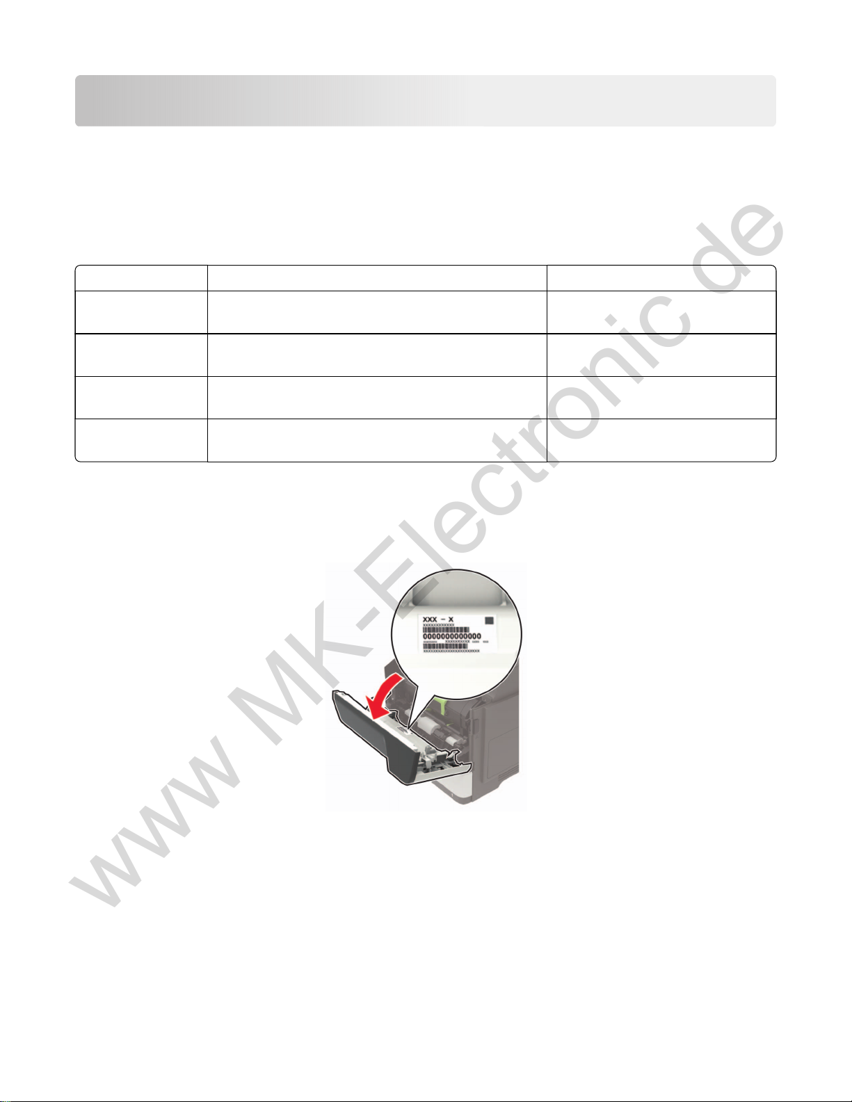
Finding the serial number
Open door A, and then find the serial number at the right side of the printer.
7018-676
7018-678
7018-676
7018-679
General information
23
Page 4

Parts catalog
www MK-Electronic de
Legend
The following column headings are used in the parts catalog:
• ASM‑index—Identifies the assembly and the item in the diagram. For example, 3‑1 indicates Assembly 3
and item 1 in the table.
• Part number—Identifies the unique number that correlates with the part.
• Units/mach—Refers to the number of units actually used in the base machine or product.
• Units/option—Refers to the number of units in a particular option.
• Units/FRU—Refers to the number of units in a particular FRU.
• Description—A brief description of the part.
The following abbreviations are used in the parts catalog:
• NS (not shown) in the Asm‑index column indicates that the part is procurable but is not pictured in the
illustration.
• PP (parts packet) in the Description column indicates that the part is contained in a parts packet.
7018
Parts catalog
380
Page 5
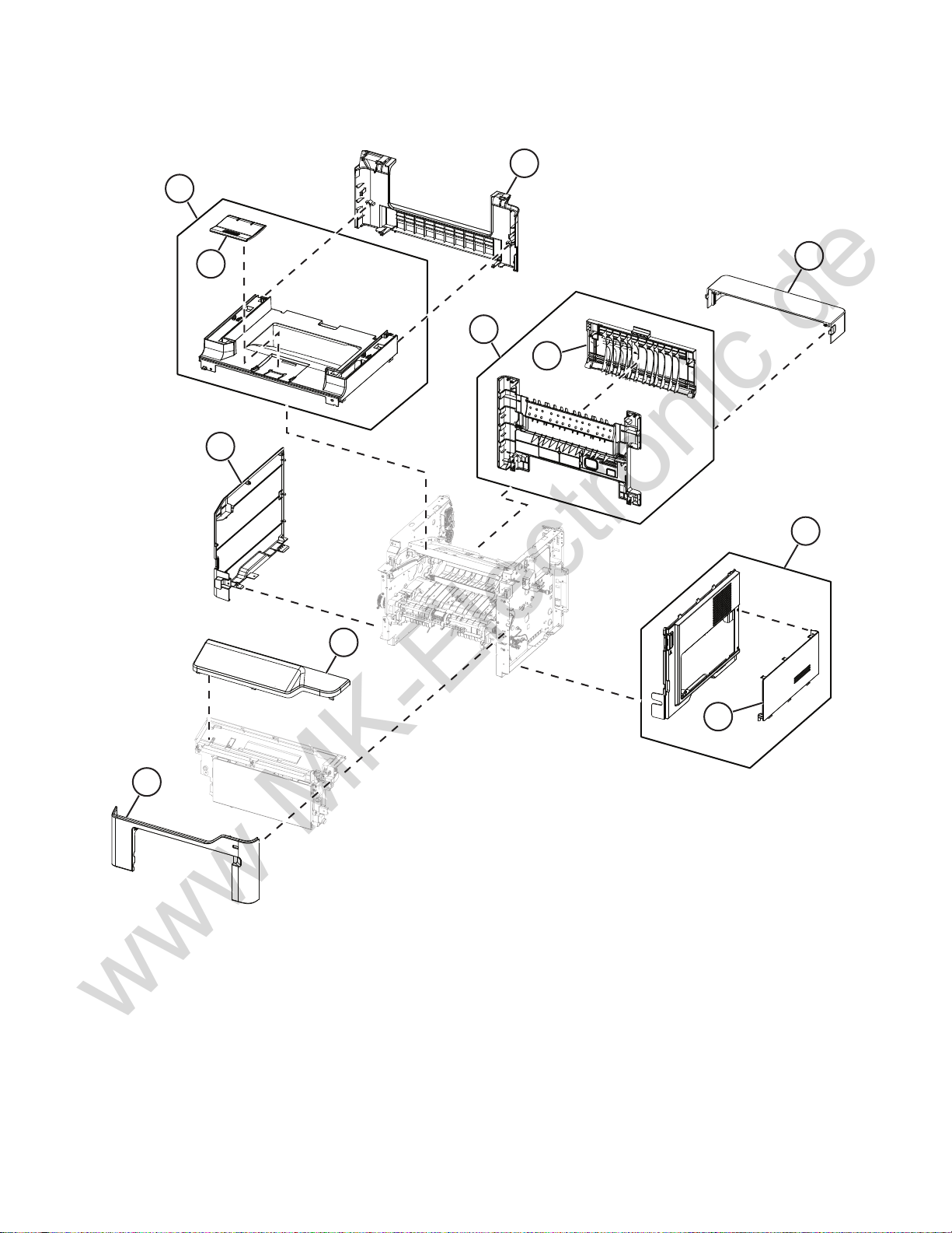
Assembly 1: Covers
www MK-Electronic de
1
7018
11
2
3
4
9
10
5
6
7
8
Parts catalog
381
Page 6
Assembly 1: Covers
www MK-Electronic de
Asm-index P/N Units/mach Units/FRU Description Removal procedure
7018
1 41X1343 1 1 Top cover
2 40X9102 1 1 Output extender --
3 41X1357 1 1 Rear door and cover
4 41X2275 1 1 Rear access door --
540X8521 1 1Dust cover --
6 41X1166 1 1 Right cover
7 41X1233 1 1 Controller board access
cover
8 41X1164 1 1 Nameplate
9 41X1168 1 1 Left cover
10 41X1358 1 1 Top access cover
11 41X2501 1 1 Scanner rear cover
“Top cover removal” on page 289
“Rear door and cover removal” on
page 287
“Right cover removal” on page 230
“Right cover removal” on page 230
“Nameplate removal” on page 245
“Left cover removal” on page 219
“Top access cover removal” on
page 247
“Scanner rear cover removal” on
page 286
Parts catalog
382
Page 7
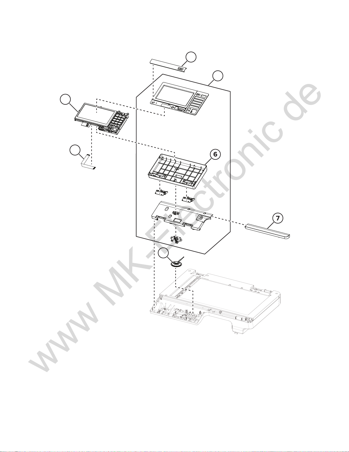
Assembly 2: Control panel
www MK-Electronic de
3
4
7018
1
2
5
Parts catalog
383
Page 8
Assembly 2: Control panel
www MK-Electronic de
Asm-index P/N Units/mach Units/FRU Description Removal procedure
7018
1 41X2439 1 1 Bezel (MX622)
2 41X2440 1 1 Control panel cover
and buttons
3 41X0051 1 1 Control panel display
assembly
4 41X2232 1 1 Control panel flat cable
541X2230 1 1Speaker
6 41X1354 1 1 Control panel rear
cover
741X1345 1 1Scanner front cover
“Bezel removal” on page 248
“Control panel covers and buttons
removal” on page 249
“Control panel display assembly
removal” on page 248
“Control panel flat cable removal” on
page 255
“Speaker removal” on page 252
“Control panel covers and buttons
removal” on page 249
“Scanner front cover removal” on
page 252
Parts catalog
384
Page 9
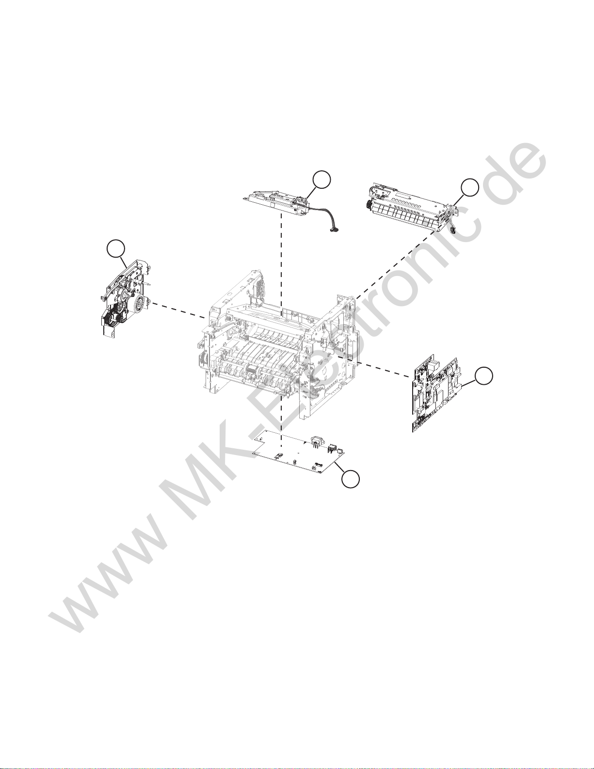
Assembly 3: Electronics 1
www MK-Electronic de
7018
1
5
2
3
4
Parts catalog
385
Page 10
Assembly 3: Electronics 1
www MK-Electronic de
Asm-index P/N Units/mach Units/FRU Description Removal procedure
7018
1 41X1185 1 1 Printhead
2 41X1178 1 1 Fuser, 110V
2 41X1179 1 1 Fuser, 220V
2 41X1180 1 1 Fuser, 100V
3 41X1363 1 1 Controller board
4 41X1201 1 1 Power supply,
100V/110V
4 41X1202 1 1 Power supply, 220V
5 41X1224 1 1 Main drive gearbox
“Printhead removal” on page 294
“Fuser removal” on page 288
“Fuser removal” on page 288
“Fuser removal” on page 288
“Controller board removal” on page
238
“Power supply removal” on page 265
“Power supply removal” on page 265
“Main drive gearbox removal” on
page 220
Parts catalog
386
Page 11
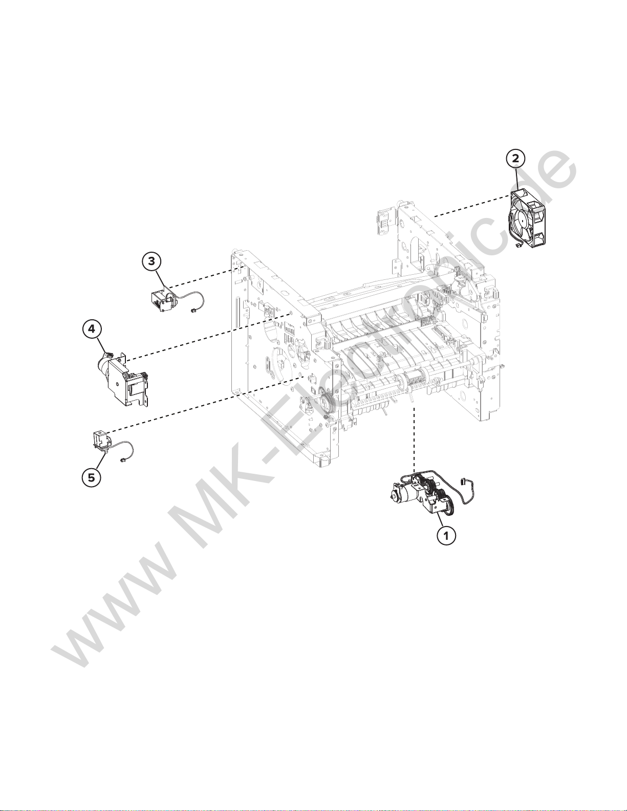
Assembly 4: Electronics 2
www MK-Electronic de
7018
Parts catalog
387
Page 12
Assembly 4: Electronics 2
www MK-Electronic de
Asm-index P/N Units/mach Units/FRU Description Removal procedure
7018
1 41X1989 1 1 Pick/lift motor
gearbox
2 41X2259 1 1 Cooling fan
3 41X1214 1 1 Reverse solenoid
4 41X1237 1 1 Cartridge gearbox
5 41X1213 1 1 MPF solenoid
“Pick/lift motor gearbox removal” on
page 283
“Cooling fan removal” on page 236
“Reverse solenoid removal” on page
226
“Cartridge gearbox removal” on
page 229
“MPF solenoid removal” on page 228
Parts catalog
388
Page 13
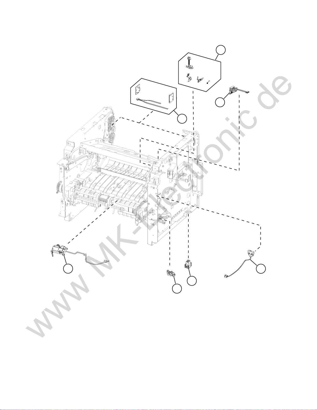
Assembly 5: Electronics 3
www MK-Electronic de
7018
1
2
3
7
5
6
Parts catalog
389
4
Page 14
Assembly 5: Electronics 3
www MK-Electronic de
Asm-index P/N Units/mach Units/FRU Description Removal procedure
7018
141X1988 1 1Sensor (cartridge
barrel)
2 41X1162 1 1 Toner cartridge smart
chip contact
3 41X2274 1 1 Sensor (bin full)
4 41X1209 1 1 Sensor (front door)
5 41X1236 1 1 Interconnect cable
6 41X1238 1 1 Sensor (tray present)
7 41X1210 1 1 Sensor (MPF paper
present)
“Cartridge barrel shutter sensor kit
removal” on page 242
“Toner cartridge smart chip contact
removal” on page 240
“Sensor (bin full) removal” on page
293
“Sensor (front door) removal” on
page 257
“Interconnect cable removal” on
page 233
“Sensor (tray present) removal” on
page 235
“Sensor (MPF paper present) removal”
on page 262
Parts catalog
390
Page 15

Assembly 6: Electronics 4
www MK-Electronic de
7018
1
2
3
4
5
6
Parts catalog
391
Page 16

Assembly 6: Electronics 4
www MK-Electronic de
Asm-index P/N Units/mach Units/FRU Description Removal procedure
7018
1 41X1208 1 1 Sensor (trailing edge)
241X1206 1 1Sensor (duplex and
input)
3 41X1238 1 1 Sensor (paper present)
4 40X8800 1 1 Paper present sensor
flag
5 40X8046 1 1 Sensor (toner density)
6 40X8044 1 1 Sensor (index)
“Sensor (trailing edge) removal” on
page 279
“Sensors (duplex and input) removal”
on page 270
“Sensor (paper present) removal” on
page 277
“Paper present sensor flag removal” on
page 280
“Sensor (toner density) removal” on
page 275
“Sensor (index) removal” on page 272
Parts catalog
392
Page 17

Assembly 7: Paper transport 1
www MK-Electronic de
6
5
4
7018
1
2
3
Parts catalog
393
Page 18

Assembly 7: Paper transport 1
www MK-Electronic de
Asm-index P/N Units/mach Units/FRU Description Removal procedure
7018
1 41X1183 1 1 Jam access cover
2 41X1184 1 1 Front input guide
3 41X1176 1 1 Duplex assembly
4 41X1182 1 1 MPF gearbox
5 41X2255 1 1 Fuser actuator
6 41X2256 1 1 Redrive gear plate
“Jam access cover removal” on page 257
“Front input guide removal” on page 263
“Duplex removal” on page 267
“MPF gearbox removal” on page 222
“Fuser actuator removal” on page 224
“Redrive gear assembly removal” on
page 288
Parts catalog
394
Page 19

Assembly 8: Paper transport 2
www MK-Electronic de
5
7018
1
4
Parts catalog
395
4
2
3
Page 20

Assembly 8: Paper transport 2
www MK-Electronic de
Asm-index P/N Units/mach Units/FRU Description Removal procedure
7018
1 40X8393 1 1 Transfer roller
2 41X1197 1 1 MPF pick roller and
separator pad
3 41X1196 1 1 Pick roller assembly
441X1198 2 2Pick tire --
5 41X1371 1 1 Redrive assembly
“Transfer roller removal” on page 256
“MPF pick roller and separator pad
removal” on page 259
“Pick roller assembly removal” on
page 272
“Redrive assembly removal” on
page 287
Parts catalog
396
Page 21

Assembly 9: MPF and standard tray
www MK-Electronic de
7018
1
3
2
Parts catalog
397
Page 22

Assembly 9: MPF and standard tray
www MK-Electronic de
Asm-index P/N Units/mach Units/FRU Description Removal procedure
7018
1 41X2605 1 1 MPF with front access cover
2 41X1987 1 1 Standard 550-sheet tray
insert
3 41X1212 1 1 Separator roller assembly --
“MPF with front access cover
removal” on page 245
--
Parts catalog
398
Page 23

Assembly 10: Optional trays
www MK-Electronic de
1
7018
2
4
3
Parts catalog
399
Page 24

Assembly 10: Optional trays
www MK-Electronic de
Asm-index P/N Units/opt Units/FRU Description Removal procedure
1 41X1216 1 1 Optional 550-sheet tray --
1 41X1217 1 1 Optional 250-sheet tray --
241X12391 1Pick roller --
3 41X1222 1 1 550-sheet tray insert (optional tray) --
3 41X1221 1 1 250-sheet tray insert (optional tray) --
7018
4 41X1212 1 1 Separator roller assembly
“Separator roller assembly
removal” on page 313
Parts catalog
400
Page 25

Assembly 11: Imaging
www MK-Electronic de
7
7018
3
12
13
Parts catalog
401
Page 26

Assembly 11: Imaging
www MK-Electronic de
Asm-index P/N Units/mach Units/FRUDescription Removal procedure
7018
1 41X1329 1 1 ADF assembly
2 41X1335 1 1 ADF tray
3 41X2221 1 1 ADF cable cover --
441X1321 1 1ADF right hinge
5 41X1324 1 1 ADF cushion --
640X9129 1 1ADF left hinge
7 41X1318 1 1 ADF access door
8 41X1326 1 1 ADF roller
9 41X1325 1 1 ADF separator roller
10 41X1322 1 1 ADF restraint pad
11 41X1332 1 1 Flatbed scanner
12 41X1315 1 1 ADF cable --
13 41X1316 1 1 ADF flat cable
“ADF assembly removal” on page 302
“ADF tray remo val ” o n pag e 299
“ADF right hinge removal” on page 304
“ADF left hinge removal” on page 303
“ADF access door removal” on page 305
“ADF roller removal” on page 298
“ADF separator roller removal” on
page 298
“ADF restraint pad removal ” on page
297
“Flatbed scanner assembly removal” on
page 306
“AD F flat cable removal” on page 308
Parts catalog
402
Page 27

Assembly 12: Fax card and hard disk
www MK-Electronic de
7018
Parts catalog
403
Page 28

7018
www MK-Electronic de
Assembly 12: Fax card and hard disk
Asm-index P/N Units/mach Units/FRUDescription Removal procedure
1 41X1374 1 1 Fax card (MX622) ‑‑
2 40X9934 1 1 Printer hard disk (MX622adhe), 500GB ‑‑
Parts catalog
404
Page 29

Assembly 13: Staple finisher option
www MK-Electronic de
7018
1
Parts catalog
405
Page 30

Assembly 13: Staple finisher option
www MK-Electronic de
Asm-index P/N Units/mach Units/FRU Description Removal procedure
7018
1 40X8121 1 1 Staple finisher option
“Staple finisher option removal” on
page 315
Parts catalog
406
Page 31

Assembly 14: Staple finisher (right)
www MK-Electronic de
2
7018
3
4
7
1
5
6
Parts catalog
407
Page 32

Assembly 14: Staple finisher (right)
www MK-Electronic de
Asm-index P/N Units/mach Units/FRU Description Removal procedure
7018
1 40X8144 1 1 Stapler interface cable
2 40X7592 1 1 Sensor (stapler access
door)
3 40X8139 1 1 Stapler door close limit
switch with cable
4 40X8142 1 1 Stapler carriage
assembly
540X8130 1 1Stapler right cover
6 40X8129 1 1 Stapler cartridge
access door
7 40X8149 1 1 Staple roll holder
“Stapler interface cable removal” on
page 339
“Sensor (stapler access door) removal”
on page 323
“Stapler door close limit switch
removal” on page 325
“Stapler carriage assembly removal”
on page 323
“Stapler right cover removal” on
page 320
“Stapler cartridge access door
removal” on page 318
“Staple roll holder removal” on
page 319
Parts catalog
408
Page 33

Assembly 15: Staple finisher (top)
www MK-Electronic de
7018
1
2
3
4
5
6
Parts catalog
409
Page 34

Assembly 15: Staple finisher (top)
www MK-Electronic de
Asm-index P/N Units/mach Units/FRU Description Removal procedure
7018
1 40X8140 1 1 Stapler service cover
2 40X8141 1 1 Stapler top cover
3 40X8137 1 1 Stapler controller
board
4 40X8125 1 1 Stapler tamper motor
5 40X8131 1 1 Sensor (stapler bin full
send)
6 40X8132 1 1 Sensor (stapler bin full
receive)
“Stapler service cover removal” on
page 333
“Stapler top cover removal” on page
341
“Stapler controller board removal” on
page 333
“Motor (stapler left tamper) removal” on
page 333 or “Motor (stapler right tamper)
removal” on page 334
“Sensor (stapler bin full send) removal”
on page 346
“Sensor (stapler bin full receive)
removal” on page 344
Parts catalog
410
Page 35

Assembly 16: Staple finisher (rear)
www MK-Electronic de
7018
Parts catalog
411
Page 36

Assembly 16: Staple finisher (rear)
www MK-Electronic de
Asm-index P/N Units/mach Units/FRU Description Removal procedure
7018
1 40X8148 1 1 Stapler cooling fan
2 40X8135 1 1 Stapler power supply
unit
2 40X8540 1 1 Stapler power supply
unit—China
3 40X8128 1 1 Stapler rear door
4 40X8458 1 1 Trapped staple access
door
5 40X8134 1 1 Sensor (stapler pass
through)
6 40X8138 1 1 Stapler rear door close
limit switch with cable
7 40X7592 1 1 Sensor (stapler rear
door)
“Stapler cooling fan removal” on
page 337
“Stapler power supply unit removal”
on page 337
“Stapler power supply unit removal”
on page 337
“Stapler rear door removal” on
page 322
“Trapped staple access door removal”
on page 332
“Sensor (stapler pass through)
removal” on page 349
“Stapler rear cover close limit switch
removal” on page 335
“Sensor (stapler rear cover) removal”
on page 330
Parts catalog
412
Page 37

Assembly 17: Staple finisher exit assembly
www MK-Electronic de
7018
Parts catalog
413
Page 38

Assembly 17: Staple finisher exit assembly
www MK-Electronic de
Asm-index P/N Units/mach Units/FRU Description Removal procedure
7018
1 40X8748 1 1 Stapler tamper main
assembly
2 40X8751 1 1 Stapler accumulator
assembly
“Tamper main assembly removal” on
page 351
“Stapler accumulator assembly
removal” on page 358
Parts catalog
414
Page 39

Assembly 18: Staple finisher tamper assembly
www MK-Electronic de
7018
Parts catalog
415
Page 40

Assembly 18: Staple finisher tamper assembly
www MK-Electronic de
Asm-index P/N Units/mach Units/FRU Description Removal procedure
7018
1 40X8754 1 1 Sensor (stapler
paddle HP)
2 40X8754 1 1 Sensor (stapler left
tamper HP)
3 40X8750 2 2 Stapler tamper drive
belt
4 40X8754 1 1 Sensor (stapler right
tamper HP)
5 40X8125 2 1 Stapler tamper motor
6 40X8749 1 1 Tamper sub-assembly
“Sensor (stapler paddle HP) removal” on
page 360
“Sensor (stapler left tamper HP)
removal” on page 359
“Tamper drive belt removal” on
page 354
“Sensor (stapler right tamper HP)
removal” on page 358
“Motor (stapler left tamper) removal” on
page 333 or “Motor (stapler right
tamper) removal” on page 334
“Tamper sub-assembly removal” on
page 352
Parts catalog
416
Page 41

Assembly 19: Staple finisher accumulator assembly
www MK-Electronic de
7018
Parts catalog
417
Page 42

Assembly 19: Staple finisher accumulator assembly
www MK-Electronic de
Asm-index P/N Units/mach Units/FRU Description Removal procedure
7018
1 40X8752 1 1 Stapler diverter
gearbox
2 40X8753 1 1 Motor (stapler paddle)
“Diverter gearbox removal” on
page 355
“Motor (stapler paddle) removal” on
page 329
Parts catalog
418
Page 43

Assembly 20: Maintenance kits
www MK-Electronic de
Asm-index P/N Units/mach Units/FRU Description Removal procedure
7018
NS 41X1227 1 1 Maintenance Kit (100 V)
• Fuser (100 V)
• MPF pick roller and separator pad
• Pick tires
• Separator roller assembly
• Transfer roller
NS 41X1225 1 1 Maintenance Kit (110 V)
• Fuser (110 V)
• MPF pick roller and separator pad
• Pick tires
• Separator roller assembly
• Transfer roller
NS 41X1226 1 1 Maintenance Kit (220 V)
• Fuser (220 V)
• MPF pick roller and separator pad
• Pick tires
• Separator roller assembly
• Transfer roller
N/A
N/A
N/A
Parts catalog
419
Page 44

7018
www MK-Electronic de
Parts catalog
420
Page 45

7018
www MK-Electronic de
Assembly 21: Miscellaneous
Asm-index P/N Units/mach Units/FRU Description Removal procedure
NS 40X9934 1 1 Hard disk, SATA --
NS 41X1010 1 1 User Flash Memory, 256MB --
NS 41X1002 1 1 Forms and Bar Code card --
NS 41X1004 1 1 IPDS card --
NS 41X1006 1 1 PRESCRIBE card --
NS 41X1014 1 1 Font card, Traditional Chinese --
NS 41X1013 1 1 Font card, Simplified Chinese --
NS 41X1015 1 1 Font card, Korean --
NS 41X1016 1 1 Font card, Japanese --
NS 41X1872 1 1 Marknet N8372, Front WiFi—FSM --
NS 40X8523 1 1 RS‑232C Serial Interface card --
NS 40X8524 1 1 Parallel 1284‑B Interface card --
NS 41X1945 1 1 MarkNet N8230 Fiber Ethernet 100BASE-
FX (LC), 1000BASE-SX (LC) (Fiber + side
backpack)
NS 41X2055 1 1 Smart card --
NS 40X1367 1 1 Parallel cable, 10 feet --
NS 40X1368 1 1 USB 2.0 cable, 2 meters --
NS 3086579 1 1 Software CD
Note: The part number is for internal use
only and is not orderable.
--
‑‑
Parts catalog
421
 Loading...