

Page 1

Lexmark OptraTM M410/M412
• Table of Contents
• Start Diagnostics
• Safety and Notices
• Trademarks
4045-XXX
•Index
Lexmark and Lexmark with diamond
design are trademarks of Lexmark
International, Inc., registered in the
United States and/or other countries.
Page 2

4045-XXX
Edition: May 2000
The following paragraph does not apply to any country where such provisions are
inconsistent with local law: LEXMARK INTERNATIONAL, INC. PROVIDES THIS
PUBLICATION “AS IS” WITHOUT WARRANTY OF ANY KIND, EITHER EXPRESS OR
IMPLIED, INCLUDING, BUT NOT LIMITED TO, THE IMPLIED WARRANTIES OF
MERCHANTABILITY OR FITNESS FOR A PARTICULAR PURPOSE. Some states do not
allow disclaimer of express or implied warranties in certain transactions; therefore, this
statement may not apply to you.
This publication could include technical inaccuracies or typographical errors. Changes are
periodically made to the information herein; these changes will be incorporated in later
editions. Improvements or changes in the products or the programs described may be
made at any time.
A form for reader’s comments is provided at the back of this publication. If the form has
been removed, comments may be addressed to Lexmark International, Inc., Department
D22A/032-2, 740 West New Circle Road, Lexington, Kentucky 40550, U.S.A. Lexmark
may use or distribute any of the information you supply in any way it believes appropriate
without incurring any obligation to you. You can purchase additional copies of publications
related to this product by calling 1-800-553-9727. In other countries, contact your point of
purchase.
Lexmark and Optra are trademarks of Lexmark International, Inc., registered in the United
States and/or other countries.
Color Jetprinter is a trademark of Lexmark International, Inc.
Other trademarks are the property of their respective owners.
© Copyright Lexmark International, Inc. 2000.
All rights reserved.
UNITED STATES GOVERNMENT RESTRICTED RIGHTS
This software and documentation are provided with RESTRICTED RIGHTS. Use,
duplication or disclosure by the Government is subject to restrictions as set forth in
subparagraph (c)(1)(ii) of the Rights in Technical Data and Computer Software clause at
DFARS 252.227-7013 and in applicable FAR provisions: Lexmark International, Inc.,
Lexington, KY 40550.
Page 3

4045-XXX
Table of Contents
Notices and Safety Information . . . . . . . . . . . . . . . . . . . . . . . . . . . . vii
Laser Notices . . . . . . . . . . . . . . . . . . . . . . . . . . . . . . . . . . . . . . . . . . . vii
Safety Information . . . . . . . . . . . . . . . . . . . . . . . . . . . . . . . . . . . . . . . xv
General Information . . . . . . . . . . . . . . . . . . . . . . . . . . . . . . . . . . . . 1-1
Options . . . . . . . . . . . . . . . . . . . . . . . . . . . . . . . . . . . . . . . . . . . . . . . 1-2
Printer Specifications . . . . . . . . . . . . . . . . . . . . . . . . . . . . . . . . . . . . 1-3
Diagnostic Information . . . . . . . . . . . . . . . . . . . . . . . . . . . . . . . . . 2-1
Start . . . . . . . . . . . . . . . . . . . . . . . . . . . . . . . . . . . . . . . . . . . . . . . . . 2-1
Service Error Codes. . . . . . . . . . . . . . . . . . . . . . . . . . . . . . . . . . . 2-2
User Status Messages . . . . . . . . . . . . . . . . . . . . . . . . . . . . . . . . 2-5
User Error Messages . . . . . . . . . . . . . . . . . . . . . . . . . . . . . . . . . . 2-9
Power-On Self Test (POST). . . . . . . . . . . . . . . . . . . . . . . . . . . . 2-14
Symptom Tables . . . . . . . . . . . . . . . . . . . . . . . . . . . . . . . . . . . . 2-15
Charge Roll Service Check . . . . . . . . . . . . . . . . . . . . . . . . . . . . 2-17
Cover Open Switch/Cable Service Check . . . . . . . . . . . . . . . . . 2-19
Dead Machine Service Check . . . . . . . . . . . . . . . . . . . . . . . . . . 2-20
Erase Lamp Service Check . . . . . . . . . . . . . . . . . . . . . . . . . . . . 2-22
Fan Service Check . . . . . . . . . . . . . . . . . . . . . . . . . . . . . . . . . . . 2-23
Fuser Service Check . . . . . . . . . . . . . . . . . . . . . . . . . . . . . . . . . 2-23
Input Sensor Service Check. . . . . . . . . . . . . . . . . . . . . . . . . . . . 2-25
Input Tray(s) Option Service Check . . . . . . . . . . . . . . . . . . . . . . 2-26
Main Drive Service Check . . . . . . . . . . . . . . . . . . . . . . . . . . . . . 2-29
Operator Panel Service Check. . . . . . . . . . . . . . . . . . . . . . . . . . 2-30
Options Service Check. . . . . . . . . . . . . . . . . . . . . . . . . . . . . . . . 2-32
Paper Feed Service Check . . . . . . . . . . . . . . . . . . . . . . . . . . . . 2-33
Parallel Port Service Check . . . . . . . . . . . . . . . . . . . . . . . . . . . . 2-35
Printhead Service Check . . . . . . . . . . . . . . . . . . . . . . . . . . . . . . 2-36
Print Quality Service Check . . . . . . . . . . . . . . . . . . . . . . . . . . . . 2-37
Serial Port Service Check . . . . . . . . . . . . . . . . . . . . . . . . . . . . . 2-47
Transfer Roll Service Check . . . . . . . . . . . . . . . . . . . . . . . . . . . 2-48
Diagnostic Aids . . . . . . . . . . . . . . . . . . . . . . . . . . . . . . . . . . . . . . . 3-1
Configuration Mode . . . . . . . . . . . . . . . . . . . . . . . . . . . . . . . . . . . . . 3-1
Print Quality Test Pages . . . . . . . . . . . . . . . . . . . . . . . . . . . . . . . 3-2
Panel Menus . . . . . . . . . . . . . . . . . . . . . . . . . . . . . . . . . . . . . . . . 3-2
PPDS Emulation . . . . . . . . . . . . . . . . . . . . . . . . . . . . . . . . . . . . . 3-3
Discard Buffered Jobs . . . . . . . . . . . . . . . . . . . . . . . . . . . . . . . . . 3-3
Download Emulation . . . . . . . . . . . . . . . . . . . . . . . . . . . . . . . . . . 3-3
iii
Page 4

4045-XXX
Demo Mode. . . . . . . . . . . . . . . . . . . . . . . . . . . . . . . . . . . . . . . . . .3-4
Restore Factory Defaults. . . . . . . . . . . . . . . . . . . . . . . . . . . . . . . .3-4
Narrow Media . . . . . . . . . . . . . . . . . . . . . . . . . . . . . . . . . . . . . . . .3-5
Exiting the Configuration Mode . . . . . . . . . . . . . . . . . . . . . . . . . . .3-5
Diagnostic Mode . . . . . . . . . . . . . . . . . . . . . . . . . . . . . . . . . . . . . . . .3-5
Exiting the Diagnostic Mode . . . . . . . . . . . . . . . . . . . . . . . . . . . . .3-5
Print Registration . . . . . . . . . . . . . . . . . . . . . . . . . . . . . . . . . . . . . .3-6
Print Tests . . . . . . . . . . . . . . . . . . . . . . . . . . . . . . . . . . . . . . . . . . .3-6
Hardware Tests. . . . . . . . . . . . . . . . . . . . . . . . . . . . . . . . . . . . . . .3-8
Input Tray Tests . . . . . . . . . . . . . . . . . . . . . . . . . . . . . . . . . . . . .3-13
Base Sensor Test . . . . . . . . . . . . . . . . . . . . . . . . . . . . . . . . . . . .3-14
Printer Setup . . . . . . . . . . . . . . . . . . . . . . . . . . . . . . . . . . . . . . . .3-14
Error Log . . . . . . . . . . . . . . . . . . . . . . . . . . . . . . . . . . . . . . . . . . .3-17
Device Tests . . . . . . . . . . . . . . . . . . . . . . . . . . . . . . . . . . . . . . . .3-17
Hardware Test Mode . . . . . . . . . . . . . . . . . . . . . . . . . . . . . . . . . . . .3-20
Operator Panel Test . . . . . . . . . . . . . . . . . . . . . . . . . . . . . . . . . .3-21
Main Motor Test . . . . . . . . . . . . . . . . . . . . . . . . . . . . . . . . . . . . .3-22
Solenoid Test . . . . . . . . . . . . . . . . . . . . . . . . . . . . . . . . . . . . . . .3-22
Tray 2 Motor Test . . . . . . . . . . . . . . . . . . . . . . . . . . . . . . . . . . . .3-23
Mirror Motor Test . . . . . . . . . . . . . . . . . . . . . . . . . . . . . . . . . . . . .3-23
Sensor Monitor Test . . . . . . . . . . . . . . . . . . . . . . . . . . . . . . . . . .3-24
Cooling Fan / Fuser Control Test . . . . . . . . . . . . . . . . . . . . . . . .3-25
Erase Lamp Test . . . . . . . . . . . . . . . . . . . . . . . . . . . . . . . . . . . . .3-26
Reset Test Mode . . . . . . . . . . . . . . . . . . . . . . . . . . . . . . . . . . . . .3-26
Engine Firmware . . . . . . . . . . . . . . . . . . . . . . . . . . . . . . . . . . . . .3-26
Printer Operation . . . . . . . . . . . . . . . . . . . . . . . . . . . . . . . . . . . . . . .3-27
Electrophotographic Process . . . . . . . . . . . . . . . . . . . . . . . . . . . . . .3-27
Paper Feeding, Transferring and Fusing . . . . . . . . . . . . . . . . . . . . .3-27
Paper Path/Sensor Locations . . . . . . . . . . . . . . . . . . . . . . . . . . . . .3-28
Cable Locations . . . . . . . . . . . . . . . . . . . . . . . . . . . . . . . . . . . . . . . .3-29
Repair Information . . . . . . . . . . . . . . . . . . . . . . . . . . . . . . . . . . . . . .4-1
Handling ESD-Sensitive Parts . . . . . . . . . . . . . . . . . . . . . . . . . . . . . .4-1
Adjustment Procedures . . . . . . . . . . . . . . . . . . . . . . . . . . . . . . . . . . .4-2
Printhead Assembly . . . . . . . . . . . . . . . . . . . . . . . . . . . . . . . . . . .4-2
Paper Alignment . . . . . . . . . . . . . . . . . . . . . . . . . . . . . . . . . . . . . .4-3
Removal Procedures . . . . . . . . . . . . . . . . . . . . . . . . . . . . . . . . . . . . .4-4
Covers . . . . . . . . . . . . . . . . . . . . . . . . . . . . . . . . . . . . . . . . . . . . . .4-4
Charge Roller . . . . . . . . . . . . . . . . . . . . . . . . . . . . . . . . . . . . . . . .4-8
Controller Board . . . . . . . . . . . . . . . . . . . . . . . . . . . . . . . . . . . . . .4-9
Cooling Fan . . . . . . . . . . . . . . . . . . . . . . . . . . . . . . . . . . . . . . . . .4-11
Developer Drive Assembly . . . . . . . . . . . . . . . . . . . . . . . . . . . . .4-13
Engine Board. . . . . . . . . . . . . . . . . . . . . . . . . . . . . . . . . . . . . . . .4-14
iv Service Manual
Page 5

4045-XXX
Fuser . . . . . . . . . . . . . . . . . . . . . . . . . . . . . . . . . . . . . . . . . . . . . 4-15
HVPS . . . . . . . . . . . . . . . . . . . . . . . . . . . . . . . . . . . . . . . . . . . . . 4-17
Inner Deflector . . . . . . . . . . . . . . . . . . . . . . . . . . . . . . . . . . . . . . 4-18
Left Side Frame . . . . . . . . . . . . . . . . . . . . . . . . . . . . . . . . . . . . . 4-20
LVPS . . . . . . . . . . . . . . . . . . . . . . . . . . . . . . . . . . . . . . . . . . . . . 4-21
Main Drive Assembly . . . . . . . . . . . . . . . . . . . . . . . . . . . . . . . . . 4-23
Multipurpose Tray . . . . . . . . . . . . . . . . . . . . . . . . . . . . . . . . . . . 4-24
Paper Alignment Assembly . . . . . . . . . . . . . . . . . . . . . . . . . . . . 4-25
Pick Roll . . . . . . . . . . . . . . . . . . . . . . . . . . . . . . . . . . . . . . . . . . . 4-27
Printhead . . . . . . . . . . . . . . . . . . . . . . . . . . . . . . . . . . . . . . . . . . 4-28
Redrive Assembly . . . . . . . . . . . . . . . . . . . . . . . . . . . . . . . . . . . 4-29
Right Side Frame . . . . . . . . . . . . . . . . . . . . . . . . . . . . . . . . . . . . 4-30
Transfer Roller . . . . . . . . . . . . . . . . . . . . . . . . . . . . . . . . . . . . . . 4-30
Connector Locations . . . . . . . . . . . . . . . . . . . . . . . . . . . . . . . . . . . 5-1
Low Voltage Power Supply . . . . . . . . . . . . . . . . . . . . . . . . . . . . . 5-1
High Voltage Power Supply . . . . . . . . . . . . . . . . . . . . . . . . . . . . . 5-2
Engine Board . . . . . . . . . . . . . . . . . . . . . . . . . . . . . . . . . . . . . . . . 5-4
Interconnect Board . . . . . . . . . . . . . . . . . . . . . . . . . . . . . . . . . . . 5-10
Option Tray Board . . . . . . . . . . . . . . . . . . . . . . . . . . . . . . . . . . . 5-12
Parts Catalog . . . . . . . . . . . . . . . . . . . . . . . . . . . . . . . . . . . . . . . . . 6-1
Assembly 1: Covers . . . . . . . . . . . . . . . . . . . . . . . . . . . . . . . . . . . 6-2
Assembly 2: Frame . . . . . . . . . . . . . . . . . . . . . . . . . . . . . . . . . . . 6-6
Assembly 3: Printhead . . . . . . . . . . . . . . . . . . . . . . . . . . . . . . . . . 6-8
Assembly 4: Paper Feed - Multipurpose Unit. . . . . . . . . . . . . . . 6-10
Assembly 5: Paper Feed - Alignment. . . . . . . . . . . . . . . . . . . . . 6-12
Assembly 6: Paper Feed - Output . . . . . . . . . . . . . . . . . . . . . . . 6-14
Assembly 7: Main Drive . . . . . . . . . . . . . . . . . . . . . . . . . . . . . . . 6-16
Assembly 8: Developer Drive. . . . . . . . . . . . . . . . . . . . . . . . . . . 6-18
Assembly 9: Fuser . . . . . . . . . . . . . . . . . . . . . . . . . . . . . . . . . . . 6-20
Assembly 10: Transfer . . . . . . . . . . . . . . . . . . . . . . . . . . . . . . . . 6-24
Assembly 11: Charging . . . . . . . . . . . . . . . . . . . . . . . . . . . . . . . 6-26
Assembly 12: Electronics . . . . . . . . . . . . . . . . . . . . . . . . . . . . . . 6-28
Assembly 13: 250-Sheet Tray . . . . . . . . . . . . . . . . . . . . . . . . . . 6-34
Assembly 14: 500-Sheet Tray . . . . . . . . . . . . . . . . . . . . . . . . . . 6-36
Assembly 15: Options . . . . . . . . . . . . . . . . . . . . . . . . . . . . . . . . 6-40
Index. . . . . . . . . . . . . . . . . . . . . . . . . . . . . . . . . . . . . . . . . . . . . . . . . . I-1
v
Page 6

4045-XXX
vi Service Manual
Page 7
4045-XXX
Notices and Safety Information
Laser Notices
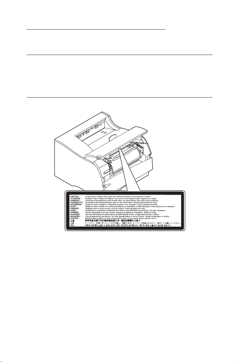
The following laser notice labels may be affixed to this printer as
shown:
Laser Advisory Label
Notices and Safety Information vii
Page 8
4045-XXX
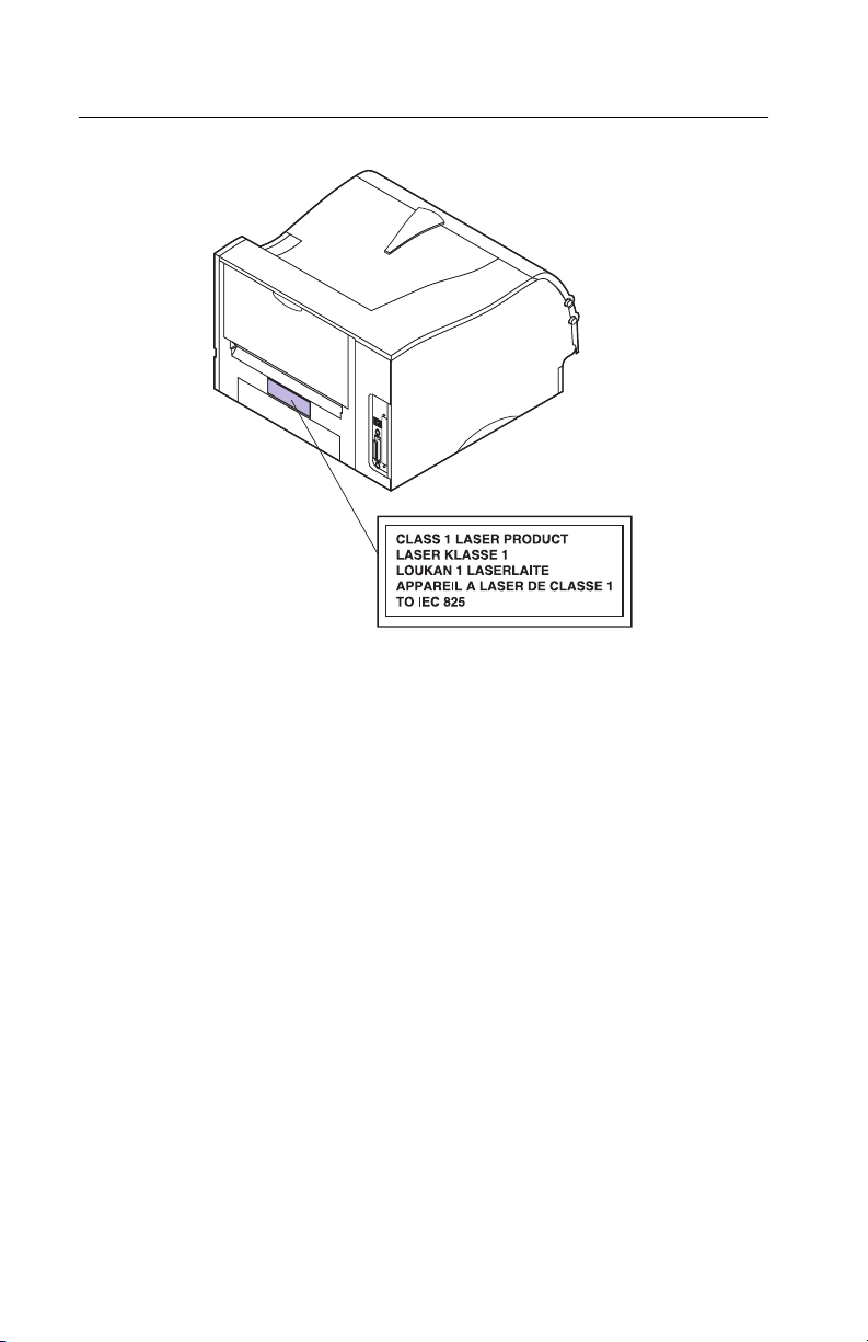
Class 1 Laser Statement Label
viii Service Manual
Page 9

4045-XXX
Laser Notice
The printer is certified in the U.S. to conform to the requirements of
DHHS 21 CFR Subchapter J for Class I (1) laser products, and
elsewhere is certified as a Class I laser product conforming to the
requirements of IEC 825.
Class I laser products are not considered to be hazardous. The
printer contains internally a Class IIIb (3b) laser that is nominally a 5
milliwatt gallium arsenide laser operating in the wavelength region of
770-795 nanometers. The laser system and printer are designed so
there is never any human access to laser radiation above a Class I
level during normal operation, user maintenance, or prescribed
service condition.
Laser
Der Drucker erfüllt gemäß amtlicher Bestätigung der USA die
Anforderungen der Bestimmung DHHS (Department of Health and
Human Services) 21 CFR Teil J für Laserprodukte der Klasse I (1).
In anderen Ländern gilt der Drucker als Laserprodukt der Klasse I,
der die Anforderungen der IEC (International Electrotechnical
Commission) 825 gemäß amtlicher Bestätigung erfüllt.
Laserprodukte der Klasse I gelten als unschädlich. Im Inneren des
Druckers befindet sich ein Laser der Klasse IIIb (3b), bei dem es
sich um einen Galliumarsenlaser mit 5 Milliwatt handelt, der Wellen
der Länge 770-795 Nanometer ausstrahlt. Das Lasersystem und der
Drucker sind so konzipiert, daß im Normalbetrieb, bei der Wartung
durch den Benutzer oder bei ordnungsgemäßer Wartung durch den
Kundendienst Laserbestrahlung, die die Klasse I übersteigen würde,
Menschen keinesfalls erreicht.
Avis relatif à l’utilisation de laser
Pour les Etats-Unis : cette imprimante est certifiée conforme aux
provisions DHHS 21 CFR alinéa J concernant les produits laser de
Classe I (1). Pour les autres pays : cette imprimante répond aux
normes IEC 825 relatives aux produits laser de Classe I.
Notices and Safety Information ix
Page 10

4045-XXX
Les produits laser de Classe I sont considérés comme des produits
non dangereux. Cette imprimante est équipée d’un laser de Classe
IIIb (3b) (arséniure de gallium d’une puissance nominale de 5
milliwatts) émettant sur des longueurs d’onde comprises entre 770
et 795 nanomètres. L’imprimante et son système laser sont conçus
pour impossible, dans des conditions normales d’utilisation,
d’entretien par l’utilisateur ou de révision, l’exposition à des
rayonnements laser supérieurs à des rayonnements de Classe I .
Avvertenze sui prodotti laser
Questa stampante è certificata negli Stati Uniti per essere conforme
ai requisiti del DHHS 21 CFR Sottocapitolo J per i prodotti laser di
classe 1 ed è certificata negli altri Paesi come prodotto laser di
classe 1 conforme ai requisiti della norma CEI 825.
I prodotti laser di classe non sono considerati pericolosi. La
stampante contiene al suo interno un laser di classe IIIb (3b)
all’arseniuro di gallio della potenza di 5mW che opera sulla
lunghezza d’onda compresa tra 770 e 795 nanometri. Il sistema
laser e la stampante sono stati progettati in modo tale che le
persone a contatto con la stampante, durante il normale
funzionamento, le operazioni di servizio o quelle di assistenza
tecnica, non ricevano radiazioni laser superiori al livello della classe
1.
Avisos sobre el láser
Se certifica que, en los EE.UU., esta impresora cumple los
requisitos para los productos láser de Clase I (1) establecidos en el
subcapítulo J de la norma CFR 21 del DHHS (Departamento de
Sanidad y Servicios) y, en los demás países, reúne todas las
condiciones expuestas en la norma IEC 825 para productos láser de
Clase I (1).
Los productos láser de Clase I no se consideran peligrosos. La
impresora contiene en su interior un láser de Clase IIIb (3b) de
arseniuro de galio de funcionamiento nominal a 5 milivatios en una
longitud de onda de 770 a 795 nanómetros. El sistema láser y la
impresora están diseñados de forma que ninguna persona pueda
verse afectada por ningún tipo de radiación láser superior al nivel de
x Service Manual
Page 11

4045-XXX
la Clase I durante su uso normal, el mantenimiento realizado por el
usuario o cualquier otra situación de servicio técnico.
Declaração sobre Laser
A impressora está certificada nos E.U.A. em conformidade com os
requisitos da regulamentação DHHS 21 CFR Subcapítulo J para a
Classe I (1) de produtos laser. Em outros locais, está certificada
como um produto laser da Classe I, em conformidade com os
requisitos da norma IEC 825.
Os produtos laser da Classe I não são considerados perigosos.
Internamente, a impressora contém um produto laser da Classe IIIb
(3b), designado laser de arseneto de potássio, de 5 milliwatts
,operando numa faixa de comprimento de onda entre 770 e 795
nanómetros. O sistema e a impressora laser foram concebidos de
forma a nunca existir qualquer possiblidade de acesso humano a
radiação laser superior a um nível de Classe I durante a operação
normal, a manutenção feita pelo utilizador ou condições de
assistência prescritas.
Laserinformatie
De printer voldoet aan de eisen die gesteld worden aan een
laserprodukt van klasse I. Voor de Verenigde Staten zijn deze eisen
vastgelegd in DHHS 21 CFR Subchapter J, voor andere landen in
IEC 825.
Laserprodukten van klasse I worden niet als ongevaarlijk
aangemerkt. De printer is voorzien van een laser van klasse IIIb
(3b), dat wil zeggen een gallium arsenide-laser van 5 milliwatt met
een golflengte van 770-795 nanometer. Het lasergedeelte en de
printer zijn zo ontworpen dat bij normaal gebruik, bij onderhoud of
reparatie conform de voorschriften, nooit blootstelling mogelijk is
aan laserstraling boven een niveau zoals voorgeschreven is voor
klasse 1.
Notices and Safety Information xi
Page 12

4045-XXX
Lasermeddelelse
Printeren er godkendt som et Klasse I-laserprodukt, i
overenstemmelse med kravene i IEC 825.
Klasse I-laserprodukter betragtes ikke som farlige. Printeren
indeholder internt en Klasse IIIB (3b)-laser, der nominelt er en 5
milliwatt galliumarsenid laser, som arbejder på bølgelængdeområdet
770-795 nanometer. Lasersystemet og printeren er udformet
således, at mennesker aldrig udsættes for en laserstråling over
Klasse I-niveau ved normal drift, brugervedligeholdelse eller
obligatoriske servicebetingelser.
Huomautus laserlaitteesta
Tämä kirjoitin on Yhdysvalloissa luokan I (1) laserlaitteiden DHHS
21 CFR Subchapter J -määrityksen mukainen ja muualla luokan I
laserlaitteiden IEC 825 -määrityksen mukainen.
Luokan I laserlaitteiden ei katsota olevan vaarallisia käyttäjälle.
Kirjoittimessa on sisäinen luokan IIIb (3b) 5 milliwatin
galliumarsenidilaser, joka toimii aaltoalueella 770 - 795 nanometriä.
Laserjärjestelmä ja kirjoitin on suunniteltu siten, että käyttäjä ei
altistu luokan I määrityksiä voimakkaammalle säteilylle kirjoittimen
normaalin toiminnan, käyttäjän tekemien huoltotoimien tai muiden
huoltotoimien yhteydessä.
VARO! Avattaessa ja suojalukitus ohitettaessa olet alttiina
näkymättömälle lasersäteilylle. Älä katso säteeseen.
VARNING! Osynlig laserstrålning när denna del är öppnad och
spärren är urkopplad. Betrakta ej strålen.
Laser-notis
Denna skrivare är i USA certifierad att motsvara kraven i DHHS 21
CFR, underparagraf J för laserprodukter av Klass I (1). I andra
länder uppfyller skrivaren kraven för laserprodukter av Klass I enligt
kraven i IEC 825.
xii Service Manual
Page 13

4045-XXX
Laserprodukter i Klass I anses ej hälsovådliga. Skrivaren har en
inbyggd laser av Klass IIIb (3b) som består av en laserenhet av
gallium-arsenid på 5 milliwatt som arbetar i våglängdsområdet 770795 nanometer. Lasersystemet och skrivaren är utformade så att det
aldrig finns risk för att någon person utsätts för laserstrålning över
Klass I-nivå vid normal användning, underhåll som utförs av
användaren eller annan föreskriven serviceåtgärd.
Laser-melding
Skriveren er godkjent i USA etter kravene i DHHS 21 CFR,
underkapittel J, for klasse I (1) laserprodukter, og er i andre land
godkjent som et Klasse I-laserprodukt i samsvar med kravene i IEC
825.
Klasse I-laserprodukter er ikke å betrakte som farlige. Skriveren
inneholder internt en klasse IIIb (3b)-laser, som består av en
gallium-arsenlaserenhet som avgir stråling i bølgelengdeområdet
770-795 nanometer. Lasersystemet og skriveren er utformet slik at
personer aldri utsettes for laserstråling ut over klasse I-nivå under
vanlig bruk, vedlikehold som utføres av brukeren, eller foreskrevne
serviceoperasjoner.
Avís sobre el Làser
Segons ha estat certificat als Estats Units, aquesta impressora
compleix els requisits de DHHS 21 CFR, apartat J, pels productes
làser de classe I (1), i segons ha estat certificat en altres llocs, és un
producte làser de classe I que compleix els requisits d’IEC 825.
Els productes làser de classe I no es consideren perillosos. Aquesta
impressora conté un làser de classe IIIb (3b) d’arseniür de gal.li,
nominalment de 5 mil.liwats, i funciona a la regió de longitud d’ona
de 770-795 nanòmetres. El sistema làser i la impressora han sigut
concebuts de manera que mai hi hagi exposició a la radiació làser
per sobre d’un nivell de classe I durant una operació normal, durant
les tasques de manteniment d’usuari ni durant els serveis que
satisfacin les condicions prescrites.
Notices and Safety Information xiii
Page 14
4045-XXX
Japanese Laser Notice
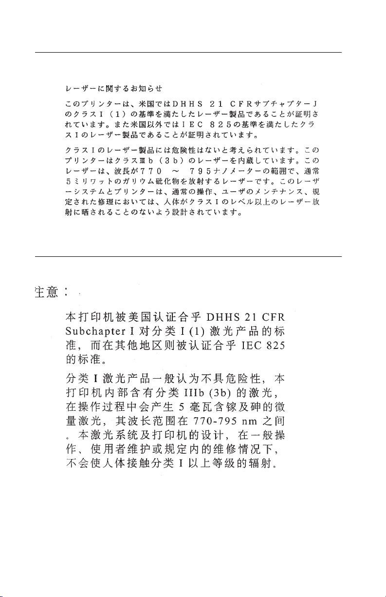
Chinese Laser Notice
xiv Service Manual
Page 15
4045-XXX
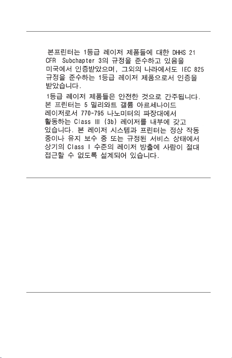
Korean Laser Notice
Safety Information
• This product is designed, tested and approved to meet strict
global safety standards with the use of specific Lexmark
components. The safety features of some parts may not always
be obvious. Lexmark is not responsible for the use of other
replacement parts.
• The maintenance information for this product has been
prepared for use by a professional service person and is not
intended to be used by others.
• There may be an increased risk of electric shock and personal
injury during disassembly and servicing of this product.
Professional service personnel should understand this and take
necessary precautions.
Consignes de Sécurité
• Ce produit a été conçu, testé et approuvé pour respecter les
normes strictes de sécurité globale lors de l'utilisation de
composants Lexmark spécifiques. Les caractéristiques de
Notices and Safety Information xv
Page 16

4045-XXX
sécurité de certains éléments ne sont pas toujours évidentes.
Lexmark ne peut être tenu responsable de l'utilisation d'autres
pièces de rechange.
• Les consignes d'entretien et de réparation de ce produit
s'adressent uniquement à un personnel de maintenance
qualifié.
• Le démontage et l'entretien de ce produit pouvant présenter
certains risques électriques, le personnel d'entretien qualifié
devra prendre toutes les précautions nécessaires.
Norme di sicurezza
• Il prodotto è stato progettato, testato e approvato in conformità a
severi standard di sicurezza e per l’utilizzo con componenti
Lexmark specifici. Le caratteristiche di sicurezza di alcune parti
non sempre sono di immediata comprensione. Lexmark non è
responsabile per l’utilizzo di parti di ricambio di altri produttori.
• Le informazioni riguardanti la manutenzione di questo prodotto
sono indirizzate soltanto al personale di assistenza autorizzato.
• Durante lo smontaggio e la manutenzione di questo prodotto, il
rischio di subire scosse elettriche e danni alla persona è più
elevato. Il personale di assistenza autorizzato, deve, quindi,
adottare le precauzioni necessarie.
Sicherheitshinweise
• Dieses Produkt und die zugehörigen Komponenten wurden
entworfen und getestet, um beim Einsatz die weltweit gültigen
Sicherheitsanforderungen zu erfüllen. Die sicherheitsrelevanten
Funktionen der Bauteile und Optionen sind nicht immer
offensichtlich. Sofern Teile eingesetzt werden, die nicht von
Lexmark sind, wird von Lexmark keinerlei Verantwortung oder
Haftung für dieses Produkt übernommen.
• Die Wartungsinformationen für dieses Produkt sind
ausschließlich für die Verwendung durch einen
Wartungsfachmann bestimmt.
• Während des Auseinandernehmens und der Wartung des
Geräts besteht ein zusätzliches Risiko eines elektrischen
Schlags und körperlicher Verletzung. Das zuständige
xvi Service Manual
Page 17

4045-XXX
Fachpersonal sollte entsprechende Vorsichtsmaßnahmen
treffen.
Pautas de Seguridad
• Este producto se ha diseñado, verificado y aprobado para
cumplir los más estrictos estándares de seguridad global
usando los componentes específicos de Lexmark. Puede que
las características de seguridad de algunas piezas no sean
siempre evidentes. Lexmark no se hace responsable del uso de
otras piezas de recambio.
• La información sobre el mantenimiento de este producto está
dirigida exclusivamente al personal cualificado de
mantenimiento.
• Existe mayor riesgo de descarga eléctrica y de daños
personales durante el desmontaje y la reparación de la
máquina. El personal cualificado debe ser consciente de este
peligro y tomar las precauciones necesarias.
Informações de Segurança
• Este produto foi concebido, testado e aprovado para satisfazer
os padrões globais de segurança na utilização de componentes
específicos da Lexmark. As funções de segurança de alguns
dos componentes podem não ser sempre óbvias. A Lexmark
não é responsável pela utilização de outros componentes de
substituição.
• As informações de segurança relativas a este produto
destinam-se a profissionais destes serviços e não devem ser
utilizadas por outras pessoas.
• Risco de choques eléctricos e ferimentos graves durante a
desmontagem e manutenção deste produto. Os profissionais
destes serviços devem estar avisados deste facto e tomar os
cuidados necessários.
Notices and Safety Information xvii
Page 18

4045-XXX
Informació de Seguretat
• Aquest producte està dissenyat, comprovat i aprovat per tal
d'acomplir les estrictes normes de seguretat globals amb la
utililització de components específics de Lexmark. Les
característiques de seguretat d'algunes peces pot ser que no
sempre siguin òbvies. Lexmark no es responsabilitza de l'us
d'altres peces de recanvi.
• La informació pel manteniment d’aquest producte està
orientada exclusivament a professionals i no està destinada a
ningú que no ho sigui.
• El risc de xoc elèctric i de danys personals pot augmentar
durant el procés de desmuntatge i de servei d’aquest producte.
El personal professional ha d’estar-ne assabentat i prendre les
mesures convenients.
xviii Service Manual
Page 19
4045-XXX
Chinese Safety Information
Korean Safety Information
Notices and Safety Information xix
Page 20

4045-XXX
xx Service Manual
Page 21
4045-XXX
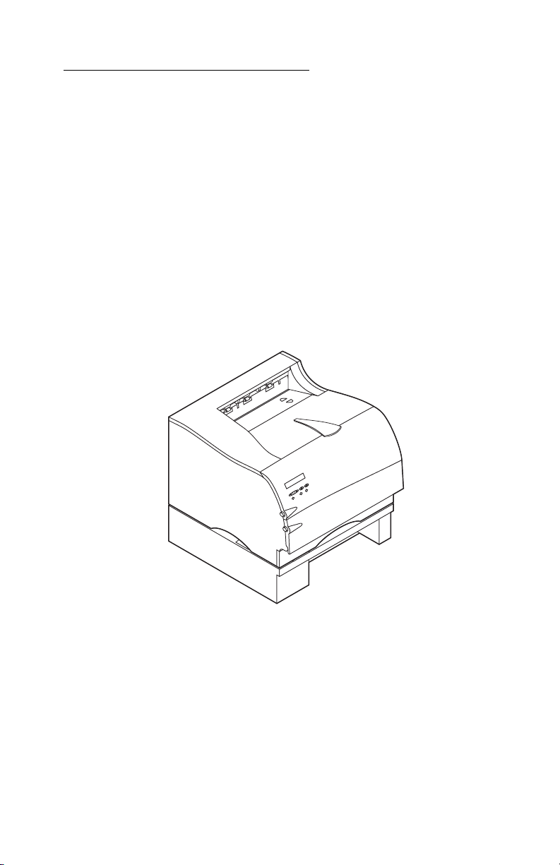
1. General Information
The Lexmark OptraTM M410 and M412 laser printers are letterquality laser page printers designed to attach to an IBM compatible
Personal Computer and to most computer networks.
The M410 printer is capable of printing at speeds of 12 pages per
minute. The M412 is capable of printing at speeds of 17 pages per
minute. Both models print with a true 600 x 600 dpi resolution or
1200 x 1200 dpi Image Quality resolution. Each model of the base
printer comes with 4MB of memory and is expandable to 132MB
using both SDRAM DIMM slots. User flash memory is also available
up to 16MB.
General Information 1-1
Page 22

4045-XXX
Options
The following options are available. Some options are not available
in every country. Contact your point of purchase for options available
in your country.
500-Sheet Drawer
SDRAM Memory DIMMs: 4MB, 8MB, 16MB, 32MB and 64MB
Flash Memory DIMMs: 2MB, 4MB, 8MB and 16MB
Internal Network Options
Token Ring
Ethernet 10/100BaseTX
10Base2/T
Tri -Po rt Car d
Hard Disk - 2.1GB
Coax/Twinax Adapter for SCS
External Network Adapter: Marknet Pro 1 and 3 series
compatible
1-2 Service Manual
Page 23

4045-XXX
Printer Specifications
Acoustics Operating: <50 dBA
Sensors Paper Present Sensing (MPF) Tray 1 inserted (only when
Environment Ozone free Blue Angel Energy Star
Warm-up less than 70 seconds (from power on to Ready)
First page time Tray 1: Less than 12 seconds from standby
Dimensions Width - 405 mm (15.9”)
Weight 14.8 Kg (32.6 lbs.) with supplies installed
Idle: <30 dBA
Sleep: background noise
Tray 2 option is installed)
Input/Exit sensors Rear Exit sensor
Tray 2: Less than 13 seconds from standby
MPF: Less than 12 seconds from standby
Height - 314 mm (12.4”)
Depth - 435 mm (17.1”)
Height of Tray 2 - 130 mm (5.1”)
Footprint - 246 square inches
General Information 1-3
Page 24

4045-XXX
Maintenance Approach
The diagnostic information in this manual leads you to the correct
field replaceable unit (FRU) or part. Use the service error codes,
user status messages, user error messages, service checks, and
diagnostic aids to determine the printer problem and repair the
failure. After you complete the repair, perform tests as needed to
verify the repair.
Tools Required For Service
Flat-blade screwdriver
#1 Phillips screwdriver
#2 Phillips screwdriver
Needlenose pliers
Diagonal pliers
Spring hook
Analog or digital multimeter
Parallel wrap plug 1319128
Serial wrap plug 1329048
Twinax/serial debug cable 1381963
Coax/serial debug cable 1381964
1-4 Service Manual
Page 25

4045-XXX
Acronyms
CSU Customer Setup
DIMM Dual In-Line Memory Module
DRAM Dynamic Random Access Memory
EDO Enhanced Data Out
EP Electrophotographic Process
EPROM Erasable, Programmable Read-Only
Memory
ESD Electrostatic Discharge
FRU Field Replaceable Unit
GB Gigabyte
HVPS High Voltage Power Supply
LASER Light Amplification by Stimulated Emission
of Radiation
LCD Liquid Crystal Display
LED Light-Emitting Diode
LVPS Low Voltage Power Supply
MROM Masked Read Only Memory
NVRAM Nonvolatile Random Access Memory
OEM Original Equipment Manufacturer
PC Photoconductor
POR Power-On Reset
POST Power-On Self Test
RIP Raster Imaging Processor
ROM Read Only Memory
SIMM Single In-Line Memory Module
SRAM Static Random Access Memory
UPR Used Parts Return
V ac Volts alternating current
V dc Volts direct current
General Information 1-5
Page 26

4045-XXX
1-6 Service Manual
Page 27

4045-XXX
2. Diagnostic Information
Start
CAUTION: Remove power from the printer before you connect or
disconnect any cable or electronic board or assembly for personal
safety and to prevent damage to the printer. Use the handholds on
the side of the printer. Make sure your fingers are not under the
printer when you lift or set the printer down.
Use the service error code, user status message, user error
message, symptom table, service checks, and diagnostic aids in this
chapter to determine the corrective action necessary to repair a
malfunctioning printer.
Service error codes are indicated by a three-digit error code. If a
service error code is displayed, go to the “Service Error Codes” on
page 2-2.
User status messages provide the user with information on the
current status of the printer. Ready is displayed on the first line of the
display unless Power Saver is invoked, and then Power Saver is
displayed. If a user status message is displayed, go to the “User
Status Messages” on page 2-5.
User error messages are indicated by a two or three-digit error code
that provides the user with information that explains a problem with a
print cartridge, paper jam, option, port, and so on. If a user error
message is displayed, go to the “User Error Messages” on page 2-9.
If your machine completes the without an error, and you have a
symptom, go to the “Symptom Tables” on page 2-15. Locate your
symptom and take the appropriate action.
If a service error code appears while you are working on the
machine, go to the “Service Error Codes” on page 2-2 and take the
indicated action for that error.
Diagnostic Information 2-1
Page 28

4045-XXX
Service Error Codes
Service Error Codes are generally non-recoverable except in an
intermittent condition when you can POR the printer to temporarily
recover from the error condition.
Error Code Action
900 RIP Software Replace the controller board.
902
Engine Software
920 Fuser Error Indicates that the fuser is below temperature when
921 Fuser Error Indicates that the fuser is below standby temperature
922 Fuser Error Fuser failed to reach standby temperature. Go to the
923 Fuser Error Fuser is too hot during printing or when printer is idle. Go
924 Fuser Error An open circuit has been detected in the Fuser
931-935
Printhead Error
931 - Printhead:
no first Hsync
932 - Printhead:
Lost Hsyncs
Indicates an unrecoverable engine software error.
Replace the engine board.
printing. Go to the “Cold Fuser Service Check” on
page 2-23.
when the printer is idle. Go to the “Cold Fuser Service
Check” on page 2-23.
“Cold Fuser Service Check” on page 2-23.
to the “Hot Fuser Service Check” on page 2-25.
Thermistor Circuit. Go to the “Hot Fuser Service Check”
on page 2-25.
These errors represent a problem with the printhead. Go
to the “Printhead Service Check” on page 2-36.
935 - Mirror Motor
unable to reach
operating speed.
936
Transport Motor
2-2 Service Manual
Indicates a problem with the main drive motor. Go to the
“Main Drive Service Check” on page 2-29.
Page 29

4045-XXX
Error Code Action
939 Controller Engine
Communications
Error
941 Controller
Code CRC
941 Controller
Font CRC
943 Controller
Font Version
944 Controller
Board Failure
945 Controller
Board Failure ASIC Failure
The controller board and the engine board cannot
communicate with one another. The controller board,
engine board or interconnect board is defective. Check
each board for correct installation and secure ground. If
no problem is found, replace the FRUs in the following
order:
controller board
engine board
interconnect board
Note: The controller software also can cause a 939 error
code. Contact your next level for software support.
Replace the controller board.
Replace the controller board.
Indicates that the controller code and FONT ROM are
incompatible.
Replace the controller board.
Replace the controller board.
946 Controller
Board Failure SRAM Failure
947 Engine
Board
953 NVRAM
Failure
954 NVRAM
Failure
960 RAM
Memory Error
Replace the controller board.
Replace the engine board.
Indicates the NVRAM chip on the engine board has
failed. Replace the engine board.
Indicates the NVRAM experienced a CRC failure.
Replace the engine board.
Indicates a DRAM Memory Error on the controller board.
Replace the controller board.
Diagnostic Information 2-3
Page 30

4045-XXX
Error Code Action
961 RAM in Slot
1 is Bad.
962 RAM in Slot
2 is Bad.
964 Emulation
Error
965 Emulation
Error
975 - 979
Network Card
Replace the SIMM in Slot 1. If this does not fix the
problem, replace the controller board.
Replace the SIMM in Slot 2. If this does not fix the
problem, replace the controller board.
Indicates a failure within the Download Emulation which
is programmed into the code overlay SIMM. The specific
error is as follows:
964 - Download Emulation CRC Failure. Checksum
Failure.
965 - Download Emulation Outdated, The Download
Emulation and the controller code are incompatible. Go
to “Download Emulation” on page 3-3.
The following errors indicate a failure with the network
card. 975 - Unrecognizable Network Card. Replace
Network Card.
976 - Unrecoverable software error in Network Card.
978 - Bad checksum while programming Network Card.
Replace Network Card.
979 - Flash parts failed while programming Network
Card.
2-4 Service Manual
Page 31

4045-XXX
User Status Messages
User Status Message Status Action
Ready or Power Saver The printer is ready to
receive and process
data.
Ready/Hex The printer is ready and
HEX Trace is active,
which is known as HEX
Trace Ready.
Busy The printer is busy
receiving or processing
data, or printing data.
Note: The printer
indicator light blinks
while the printer is
processing data.
Press Menu> or
<Menu to take the
printer out of Ready
and enter all the
Menus except the
TESTS MENU (Busy
State).
Press Menu> or
<Menu to take the
printer out of Ready
and enter the TESTS
MENU (Busy State).
Press Select for the
values. Press Menu>
until Reset Printer is
on the second line of
the display. Press
Select to Reset the
printer.
Press Stop to take the
printer out of Busy.
The Not Ready
message is displayed.
No more data is
processed, but the
printer processes all
paper currently in the
printer paper path.
Press Go to return to
Ready.
Flushing Buffer The printer is flushing
corrupted print data and
the current print job is
being discarded.
No button actions are
possible while this
message is displayed.
Diagnostic Information 2-5
Page 32

4045-XXX
User Status Message Status Action
Printing Menu Settings The printer is processing
or printing a list of
current settings menus
because Print Menu
Settings is selected from
the menu.
Printing Directory List A directory of the flash
and disk contents is
processing or printing
because Print Directory
is selected from the
menu.
Press Stop to take the
printer out of Ready.
The Not Ready
message is displayed.
No more data is
processed, but the
printer processes all
paper currently in the
printer paper path.
Press Go to return to
Ready after the page
prints. Press Menu>
or <Menu to take the
printer out of Ready
and enter the TESTS
MENU (Busy State).
Press Select for the
values. Press Menu>
until Reset Printer is
on the second line of
the display. Press
Select to reset the
printer.
Press Stop to take the
printer out of Ready.
The Not Ready
message is displayed.
No more data is
processed, but the
printer processes all
paper currently in the
paper path. Press Go
to return to Ready
after the page prints.
Press Menu> or
<Menu to take the
printer out of Ready
and enter the TESTS
MENU (Busy Stat).
Press Select for the
values. Press Menu>
until Reset Printer is
on the second line of
the display. Press
Select to reset the
printer.
2-6 Service Manual
Page 33

4045-XXX
User Status Message Status Action
Restoring Factory
Defaults
Performing Self Tests The printer is running
Not Ready
(Press Go)
Resetting Printer The printer is deleting
The printer is restoring
factory defaults.
the normal series of
start-up tests after it is
powered On. When the
tests are complete, the
printer returns to Ready.
The printer is in the Not
Ready state, which
means it is not ready to
receive or process data.
This message displays
when Menu> or <Menu
is pressed during a print
job.
any print jobs in process
and restoring all settings
to user defaults.
No button actions are
possible while this
message is displayed.
No button actions are
possible while this
message is displayed.
Press Go to take the
printer out of the Not
Ready state. Press
Menu> or <Menu to
take the printer out of
Ready and enter the
TESTS MENU (Busy
state). Press Menu>
until Reset Printer is
on the second line of
the display. Press
Select to reset the
printer.
No button actions are
possible while this
message is displayed.
Formatting Flash
(Do Not Power Off)
Program Flash
(Do Not Power Off)
Formatting Disk The disk is being
The flash memory is
being formatted.
The flash memory is
being programmed,
which means fonts or
macros are being written
to flash memory.
formatted.
No button actions are
possible while this
message is displayed.
Do not perform any
button actions while
this message is
displayed.
No button actions are
possible while this
message is displayed.
Diagnostic Information 2-7
Page 34

4045-XXX
User Status Message Status Action
Programming Disk
(Do Not Power Off)
Menus Disabled The printer menus have
Activating Menu
Changes
The disk is being
programmed, which
means fonts or macros
are being written to disk.
been disabled. This
occurs when Menu> or
<Menu is pressed while
the printer is Ready and
Menu Lockout is active.
The printer display
shows this message for
one second and then
returns to the Ready
message.
The printer is reset to
activate a printer setting
changed in the menus.
No button actions are
possible while this
message is displayed.
Note: If information is
written to flash
memory and to disk at
the same time, the
Program Flash
message is displayed.
No button actions are
possible while this
message is displayed.
No button actions are
possible while this
message is displayed.
2-8 Service Manual
Page 35

4045-XXX
User Error Messages
User Error Message Explanation
200 Paper Jam
Remove Cartridge
201 Paper Jam
Remove Cartridge
202 Paper Jam
Open Rear Door
203 Paper Jam
Short Paper
250 Paper Jam
Check MP Feeder
Insert Cartridge or Close
Door
34 Short Paper The printer determines the paper length is too
Paper is jammed at the printer Input Sensor.
Open the printer’s upper front door and remove
the print cartridge to access the paper jam area.
Paper is jammed between the printer’s input and
exit sensors. Open the printer’s upper front door
and remove the print cartridge to access the jam
area.
Paper is jammed at the printer exit sensor. Open
the printer rear door to access the jam area.
Paper stops behind the rear door when feeding to
the top output bin. Paper or envelopes that are
shorter than 6.2 inches (157.5 mm) in length must
exit through the rear exit.
Paper is jammed in the multipurpose feeder.
This message displays when the printer’s front
door is open or the print cartridge is missing.
If this message cannot be cleared go to “Cover
Open Switch/Cable Service Check” on page 2-19.
short to print the formatted data. This occurs
when the printer does not know the actual paper
size loaded in the tray. For auto-size sensing
trays, this error occurs if the paper stop is in the
incorrect position. Make sure the Paper Size
setting is correct for the size paper that is being
used.
35 Res Save Off
Deficient Memory
37 Insufficient Collation
Memory
38 Memory Full This message is displayed when the printer
This message displays when the printer has
insufficient memory to enable Resource Save.
Modification of user settings that use memory can
cause this error.
This message is displayed when the printer
memory used to store pages is too full to collate
the print job.
memory used to store pages is full.
Diagnostic Information 2-9
Page 36

4045-XXX
User Error Message Explanation
39 Complex Page This message is displayed when the page is too
51 Defective Flash This message is displayed when the printer
52 Flash Full This message is displayed when there is not
53 Unformatted Flash This message is displayed when the printer
54 Network Software
Error
56 Parallel Port Disabled This error is displayed when data is sent to the
complex to print.
detects a defective flash. This error may occur at
power on, or during flash format and write
operations. Press Go to clear the message. The
flash is marked as bad and normal operation
continues. Flash operations are not allowed until
the problem is resolved.
enough free space in the flash memory to hold
the resources that have been requested to be
written to flash.
detects an unformatted flash at power on. Press
Go to clear the message. The flash is marked as
bad and normal operation continues. Flash
operations are not allowed until the flash is
formatted.
This error is displayed when the connection to the
network port is lost during power on. Press Go to
clear the message. The printer clears the setting,
but no communication can exist with the network
until the network software is reloaded.
printer across the parallel port, but the parallel
port has been disabled. Once this message is
displayed, reporting of further errors is
suppressed until the menus are entered, or the
printer is reset.
61 Defective Disk This error code is displayed when the printer
detects a defective disk. This error may occur at
power on or during disk format and write
operations. The following actions may be taken
while this message is displayed: Press Go to
clear the message. The disk is marked defective
and normal printer operations continue. Disk
operations are not allowed with a defective disk.
The Format Disk menu is not shown.
2-10 Service Manual
Page 37

4045-XXX
User Error Message Explanation
62 Disk Full This error code is displayed when there is not
63 Unformatted Disk This error code displays when the printer detects
enough free space on the disk to hold the
resources that have been requested to be written
to the disk. This message displays for both
resource and PostScript Disk operators when the
disk is full.
an unformatted disk at power on. Press Go to
clear the message. The disk is marked as bad
and normal operation continues. Disk operations
are not allowed until the disk is formatted.
User Line 2 Messages
If none of the conditions exist that are listed in the following table,
line 2 is blank. If any of the messages in the table are displayed the
following actions can be taken:
Press Menu> or <Menu to take the printer offline and access the
Ready Menu group.
Note: The Menu buttons are not active if Menu Lockout is turned
on.
Press Stop to take the printer offline. The Not Ready message is
displayed. No more data is processed from the host computer. Press
the Go button to return the printer to the Ready state.
User Message Explanation
Tray 1 Missing This message displays when tray 1 is missing and
tray 2 is installed.
Diagnostic Information 2-11
Page 38

4045-XXX
User Line 2 Link Messages
If the printer is locked on a particular link, the link indication displays.
If the printer is ready to process any link, no messages display. The
link messages are listed in the following table.
User Message Explanation
Check Configuration ID The printer configuration ID is not set or is invalid.
This condition can only be cleared when a valid
configuration ID is set. Go to “Setting
Configuration ID” on page 3-15.
Parallel This is the host interface from which the printer is
Serial
Network
LocalTalk
Infrared
USB
Fax
currently drawing data.
2-12 Service Manual
Page 39

4045-XXX
Check Device Connection Messages
The messages in the following table display when the printer looses
communications with one of the following devices.
User Status Message Explanation
Check Tray 2
Connection
This message can occur in two ways. The
specified device could have been removed from
the printer, for instance to clear a paper jam.
Otherwise, the device can still be attached to the
printer, but is experiencing a communications
problem, not fully connected, or having a
hardware failure.
If the device is temporarily removed or not
connected properly, then reattach it. When the
option is recognized, the printer automatically
clears the error and continues.
If the option is experiencing a hardware problem,
turn the printer off and back on. If the error occurs
again, turn the printer off, remove the option and
call for service.
Diagnostic Information 2-13
Page 40

4045-XXX
Power-On Self Test (POST)
When you turn the printer On, it performs a Power-On Self Test.
Check for correct POST functioning of the base printer by observing
the following:
1. The LED comes on.
2. The operator panel displays one row of pels, and then clears.
3. The operator panel displays one and a half rows of diamonds,
and then clears.
4. “Performing Self Test” appears on the display.
5. “Ready” appears on the display.
6. The fuser lamp turns on. The fuser takes longer to warm up
from a cold start than a warm start.
7. The cooling fan turns on and runs full speed.
8. The main drive motor turns on.
9. The developer drive assembly drives the developer shaft in the
toner cartridge.
10. The exit rollers turn.
11. The printhead mirror motor turns on.
12. The cooling fan turns on and runs slowly.
13. The main drive motor turns off.
14. The exit rollers stop turning.
15. The printhead mirror motor turns off.
16. The LED stays on solid and the operator panel displays
“Ready”.
2-14 Service Manual
Page 41

4045-XXX
Symptom Tables
Symptom Action
Dead Machine Go to the “Dead Machine Service
Operator Panel - One or more
buttons do not work.
Operator Panel - Display is blank.
Printer sounds 5 beeps.
Operator Panel - Display is blank.
Printer does not emit 5 beeps.
Operator Panel continuously
displays all diamonds, sounds five
beeps and does not complete
POST.
Paper feed problems - Base
printer or Integrated 250 Paper
Tr a y
Paper jams at exit of Redrive
Assembly.
Print quality - Black page Go to “Print Quality - All Black Page”
Print quality - Blank page Go to “Print Quality - Blank Page” on
Check” on page 2-20.
Go to the “Operator Panel Buttons
Service Check” on page 2-30.
Go to the “Operator Panel Service
Check” on page 2-30.
Replace the operator panel
assembly.
Go to the “Operator Panel Service
Check” on page 2-30.
Go to the “Paper Feed Service
Check” on page 2-33.
Go to the “Paper Feed Service
Check” on page 2-33.
on page 2-38.
page 2-38.
Print quality - Light print Go to “Print Quality - Light Print” on
Print quality - Background Go to “Print Quality - Background”
Print quality - Residual image Go to “Print Quality - Residual
Print quality - Skew Go to the “Paper Feed Service
Print quality - Banding Go to “Print Quality - Banding” on
Print quality - Random marks Go to “Print Quality - Random
page 2-46.
on page 2-42.
Image” on page 2-45.
Check” on page 2-33.
page 2-44.
Marks” on page 2-39.
Diagnostic Information 2-15
Page 42

4045-XXX
Symptom Action
Print quality - Toner on backside
of printed page.
Print quality - Vertical black bands
on edge of copy.
Paper feed problem with 500
sheet paper tray option.
Go to “Print Quality - Toner on
backside of printed page” on
page 2-47.
Go to “Print Quality - Black bands on
outer edges of the page” on
page 2-44.
Go to “Input Tray(s) Option Service
Check” on page 2-26.
2-16 Service Manual
Page 43

4045-XXX
Service Checks
Note: Anytime the engine board is replaced, the Configuration ID
must be reset in NVRAM on the new engine board.
Review the following information before performing any service
checks.
• Paper feed Problems (especially paper jams): Go to “Viewing
the Error Log” on page 3-17 and check the printer error log for
indications of repetitive entries that help to isolate a problem to
a particular area of the printer or option.
• Paper feed Problems with error message: Use the “User Error
Messages” on page 2-9 to help diagnose the problem.
• Print Quality Problems: Go to “Print Quality Test Pages” on
page 3-2 and print a test page to help diagnose problems
before changing any settings or working on the printer.
• Use the resident diagnostics test provided to help isolate a
problem before taking the machine apart or removing any
options.
Charge Roll Service Check
Service Tip: Close and evenly spaced repetitive marks 47.5 mm
apart or spots on the page can be caused by a damaged or
contaminated charge roll.
FRU Action
1 Charge Roll Assembly Check the charge roll for correct
2 Left Side Charge Roll Arm
and Bushing
installation, toner buildup, marks,
cuts or other signs of contamination
or damage. Replace as necessary.
Check the left side charge roll arm
and bushing for correct assembly
operation. Check for damage to the
arm or bearing assembly.
Diagnostic Information 2-17
Page 44

4045-XXX
FRU Action
3 Right Side Charge Roll Arm
and Bushing
Check the right side charge roll arm
and bushing for correct assembly
operation. Check the right charge roll
bushing for signs of wear or
contamination. Excessive
contamination could cause
intermittent charging of the charge
roll. If incorrect, replace the bushing.
Check for continuity from the
bushing to the charge roll high
voltage contact on the right side
frame. If incorrect, replace the right
charge roller arm.
Note: The screw that attaches the
charge roll lead to the contact must
be secure.
2-18 Service Manual
Page 45

4045-XXX
Cover Open Switch/Cable Service Check
FRU Action
1 Toner Cartridge Check the toner cartridge to make
2 Cover Open Switch/Cable
Assembly
sure it is correctly installed and that
the right and left cartridge tracks are
not loose or broken. Check to make
sure the cover open switch activation
tab on the toner cartridge is not
broken and that the tab correctly
activates the cover open switch
spring.
Check the cover open switch for
proper mechanical operation. If
incorrect, repair as necessary.
Disconnect the cover open switch
cable from J4 at the engine board
and measure the voltage at J4-6. It
measures approximately +5 V dc. If
the voltage is incorrect, replace the
engine board. If the voltage is
correct, check for ground at J4-8. If
incorrect, replace the engine board.
If the ground is correct, check the
continuity between J4-6 and J4-7 on
the cable. If no change in continuity
occurs as the switch is activated,
replace the cover open switch/cable
assembly. If the continuity changes
as the switch is activated, replace
the engine board.
Note: It is easier to check the
voltages on J4 with the controller
board removed.
Diagnostic Information 2-19
Page 46

4045-XXX
Dead Machine Service Check
Note: Remove any paper handling options before servicing the
printer for a dead machine condition. Observe all necessary ESD
precautions when removing and handling the controller board,
engine board or any of the installed option cards or assemblies.
Service Tip: The LVPS uses a self-docking connector that mates
with another connector mounted on the left side frame assembly.
Some force may be required to pull the LVPS loose from the
connector.
FRU Action
1 Line Voltage Check the AC line voltage. If the line
2 AC Line Cord Check the line cord for any signs of
3 +24 V dc at Tray 2
Connector
4 Controller Board Remove the controller board. Turn
5 Engine Board Test Points Check for +5 V dc at the TP5 test
6 LVPS Fuse F1 Remove the LVPS from the printer
voltage is incorrect, inform the
customer.
damage. If correct, check the
continuity of the line cord and
replace if necessary.
Check for +24 V dc at pin 7 of the
tray 2 connector located under the
printer. If +24 V dc is present at the
connector, go to step 9. If +24 V dc is
not present, go to step 4.
on the printer. If the printer powers
on in the Hardware Test Mode,
replace the controller board. If the
printer does not power on, go to step
5.
point and +24 V dc at the TP6 test
point on the engine board. If correct,
replace the engine board. If
incorrect, go to step 6.
and check fuse F1. Replace the fuse
if the fuse is blown.
2-20 Service Manual
Page 47

4045-XXX
FRU Action
7 LVPS Fuse F1 - Continues
to blow after LVPS installed
in the printer.
8 LVPS Remove the LVPS from the machine.
9 Engine Board Turn the printer off and disconnect
Replace fuse F1 if necessary. Turn
the LVPS on/off switch Off and
connect the AC line cord and turn
the LVPS On.
CAUTION: Before checking fuse F1
turn the LVPS Off and disconnect
the AC line cord. Check fuse F1. If
the fuse is blown, replace the LVPS.
CAUTION: Before making any
measurements on the LVPS output
connector, observe all necessary
safety precautions before applying
AC power. Measure the voltages on
LVPS output connector CN1. If any
voltages are incorrect, replace the
LVPS.
all the cables from the engine board.
Check for +5 V dc at TP5 test point
and +24 V dc at test point TP6 on
the engine board. If incorrect,
replace the FRUs in the following
order:
engine board
interconnect board
If correct, turn the printer off and
reconnect one cable at a time until
you find the defective assembly.
Service Tip: A short or low
resistance load that is attached to
the engine board can cause the
LVPS to overcurrent and shut the
+5 V dc supply down to 0 V dc.
Diagnostic Information 2-21
Page 48

4045-XXX
Erase Lamp Service Check
Error code 928 may be displayed when the printer detects that the
erase lamp assembly, cable or engine board is defective.
Note: If the erase lamp assembly is defective, both the erase lamp
and lens are replaced as a kit.
Make the following checks when a 928 service error displays.
FRU Action
1 Cable, Front Harness Check the connection of the front
2 Engine Board Remove the controller board and
harness to connector J10 on the
engine board for correct installation.
If incorrect, repair as necessary.
Check the front harness to erase
lamp assembly for correct
installation. If incorrect, repair as
necessary.
toner cartridge from the machine.
Perform the Erase Lamp Test in the
Hardware Test Mode. The erase
lamps turn on. The lamps can be
observed through the front of the
machine with the cover open and
print cartridge removed. If the lamps
do not turn on, measure the voltage
on J12-1. The voltage reads
approximately +24 V dc. If incorrect,
replace the engine board. If correct,
check the voltage at J12-2. The
voltage reads between 0.6 V dc to
0.8 V dc. If incorrect, check the
continuity of the erase lamp cable. If
incorrect, replace the cable. If
correct, replace the erase lamp
assembly.
2-22 Service Manual
Page 49

4045-XXX
Fan Service Check
Check the cable connections at J13 on the engine board and at the
main fan assembly. The main fan runs continuously when the printer
is powered on unless the printer is in the Power Saver mode.
FRU Action
1 Fan Manually spin the fan and check that
2 Engine Board Check the continuity of the cable. If
it rotates freely. Check the cable
connection to the engine board, J13
for correct installation.
incorrect, replace the cable. Perform
the Cooling Fan Test in the
Ha rd wa re Tes t Mo de . Tu rn t he
cooling fan on to slow or fast.
Disconnect the fan connector at J13
and measure the voltage. The
voltage measures
+24 V dc. If correct, replace the fan.
If incorrect, replace the engine
board.
Fuser Service Check
Cold Fuser Service Check
Error codes 920, 921, and 922 may display for a cold fuser failure. A
920 error caused by low line voltage can sometimes be cleared by
turning the machine off and then on again.
Service Tip: Set the Fuser Temperature to NORMAL before starting
this service check.
Diagnostic Information 2-23
Page 50

4045-XXX
FRU Action
1 Fuser Lamp Remove the controller board and run
2 LVPS Turn the printer off. Disconnect the
the Cooling Fan Test in the
Hardware Test Mode. Observe the
lamp through the left side frame. If
the lamp doesn’t come on, unplug
the printer and check the continuity
between the two pins on the fuser
lamp cable going to the fuser
assembly. If you do not measure
continuity, remove the fuser
assembly and check the continuity of
the lamp. If incorrect, replace the
lamp. If correct, replace the contact
in the fuser cover.
fuser lamp connectors at the fuser
assembly. Turn the printer on and
check across the cable for line
voltage. If incorrect, remove the
LVPS and check both F1 and F2
fuses. Remove the LVPS from the
printer. Replace any open fuses and
attach the power cord. If the fuses
open, replace the LVPS. If the fuses
open after the lamp cables are
connected to the fuser, the fuser
lamp circuit is shorted. Inspect the
fuser lamp contacts in the fuser
cover. Replace the contacts as
necessary.
3 Thermistor Disconnect the thermistor cable from
the engine board. The resistance is
as follows:
HOT - 1K ohms
COLD = 150K ohms to 475K ohms
2-24 Service Manual
Page 51

4045-XXX
Hot Fuser Service Check
Error codes 923 and 924 may display for a hot fuser failure.
CAUTION: The fuser may be hot, use caution before removing or
servicing.
FRU Action
1 Fuser Thermistor Check for damage to the thermistor
2 Engine Board Error code 924 indicates the engine
3 Fuser Hot Roll
Backup Roll Bearings
assembly. Check the resistance of
the themistor:
HOT - 1K ohms
COLD =150K ohms to 475K ohms
With the cable connected, check the
continuity from J8-6 and J8-7 to
ground. If there is continuity, replace
the fuser thermistor.
board detects an open circuit in the
thermistor circuit for the fuser
assembly. The voltage on J8-6 on
the engine board measures
approximately +5 V dc. If incorrect,
replace the engine board.
Examine the fuser assembly for
signs of overheating or damage.
Check the hot roll and backup roll for
signs of excessive toner, label glue,
labels or other contaminants. If any
are found, repair as necessary or
replace the fuser assembly.
Input Sensor Service Check
Service Tip: Run the Base Sensor Test. Check the input sensor for
proper operation. The display changes from open to closed as the
sensor flag is manually moved in and out of the sensor.
Diagnostic Information 2-25
Page 52

4045-XXX
Service Tip: Run the Sensor Monitor Test in the Hardware Test
Mode with the controller board removed.
FRU Action
1 Input Sensor Flag Check the input sensor flag for
2 Engine Board Check for approximately +5 V dc at
3 Input Sensor Cable Check the continuity of the input
damage and proper operation. If a
problem is found, repair as
necessary.
J2-3 on the engine board. If
incorrect, replace the engine board.
sensor cable. If incorrect, replace the
cable. If correct, replace the input
sensor assembly.
Input Tray(s) Option Service Check
500-Sheet Input Tray Option
Service Tip: Try all the other input paper sources to make sure they
are properly feeding paper. Run the Tray 2 Motor Test in the
Hardware Test Mode to verify motor and related paper feed
components are working properly. With the motor on, actuate the
tray 2 solenoid from the Solenoid Test to feed paper.
2-26 Service Manual
Page 53

4045-XXX
Printer does not recognize Tray 2 is installed
FRU Action
1 Tray 2 Interconnect Cable Make sure the printer is positioned
correctly on top of tray 2. The tray 2
interconnect cable contacts must
engage the tray 2 cable on the base
printer. Replace the cable if the
contacts are defective.
Printer displays message “Insert Tray 1” when trying to print from
Tray 2
FRU Action
1 Tray 1 Inserted Sensor Check the tray 2 option for correct
installation with the base printer. Run
the Sensor Test in the Hardware Test
Mode to verify the printer detects the
tray 1 present sensor. If the sensor is
not detected, check the sensor for
correct installation and connection at
the tray 2 board. If the installation is
correct, replace the sensor.
200 Paper Jam message displays, paper is jammed before the
input sensor OR Tray 2 Empty message displays when tray 2 has
paper in the tray.
FRU Action
1 Paper Path/Guides/Tray 2 Check the paper path for any foreign
2 Pick Roll Check the pick roll for signs of wear
3 Solenoid Check the solenoid for correct
objects. Make sure tray 2 is fully
installed and the lift plate raises
when the tray is inserted.
and correct installation. Replace as
necessary.
operation. Use the Solenoid Test to
check for correct operation. Replace
as necessary.
Diagnostic Information 2-27
Page 54

4045-XXX
FRU Action
4 Tray 2 Motor Use the Tray 2 Motor Test to check
the tray 2 motor. Replace as
necessary.
2-28 Service Manual
Page 55

4045-XXX
Main Drive Service Check
Service Tip: Excessive gear or main drive assembly noise is usually
caused by a defective motor assembly or engine board.
Service Tip: If there are equally spaced horizontal lines across the
page, go to “Print Quality - Evenly spaced horizontal lines or marks”
on page 2-41.
WARNING: Whenever the gearbox assembly is removed from the
machine it must be handled very carefully. Do not allow any of the
gears to come in contact with any metal or other hard surface to
avoid gear damage. It is also very important not to let any dirt, paper,
staples or other material come intact with the grease in the gearbox
assembly.
FRU Action
1 Main Drive Assembly
(Excessive noise or
vibration)
2 Main Drive Motor Cable Check the continuity of the main
Remove the controller board and run
the Main Motor Test in the Hardware
Test Mode. If the noise goes away
with the toner cartridge removed,
inform the customer to replace the
toner cartridge. Determine if the
noise is in the main drive assembly,
fuser, developer drive assembly or
alignment assembly. Look for any
loose, worn or binding parts in all
assemblies. Repair as necessary.
If a service error code 936 Transport Motor message displays,
check the voltage at J3-6 and J3-8
on the engine board. The voltages
measure approximately +5 V dc
when the motor is not running and
go to 0 V dc when the motor is
running. If incorrect, replace the
engine board.
drive motor cable. If incorrect,
replace the cable.
Diagnostic Information 2-29
Page 56

4045-XXX
FRU Action
3 Motor does not turn, no
gear error code 936 or User
message 201 Paper Jam
displays.
Check the voltages at J3 on the
engine board with the main motor
cable connected.
J3-1 - +24 V dc
J3-2 - +24 V dc
J3-3 - Ground
J3-4 - Ground
J3-5 - +2.5 V dc
J3-7 - +5 V dc
J3-9 - +5 V dc
If any voltage is incorrect, replace
the FRUs in the following order:
main drive motor assembly
engine board
Operator Panel Service Check
Operator Panel Buttons Service Check
Note: Before continuing with this service check do the “Button Test”
on page 3-9 and “Operator Panel Test” on page 3-21.
FRU Action
1 Operator Panel Assembly If any button fails the Button Test,
2 Engine Board
(No buttons work)
replace the operator panel assembly.
Check the voltage at J1-2. The
voltage measures approximately
+5 V dc with the controller board
removed. If incorrect, replace the
engine board. If correct, check the
continuity of the operator panel
cable. If incorrect, replace the cable.
If correct, replace the operator panel
assembly.
2-30 Service Manual
Page 57

4045-XXX
Operator Panel Display Service Check
SERVICE TIP: The printer has detected a problem with the engine
board, operator panel cable or operator panel assembly if POST
does not complete and the printer emits 5 beeps and stops in a
continuous pattern until the printer is turned off. The operator panel
cable is an individual cable on some printers and a combination
cable assembly with the cover switch cable on later models.
Note: If the operator panel is operating properly except for a PEL or
a few PELS missing or broken, run the “LCD Test” on page 3-8 from
the hardware tests before continuing with this diagnostic service
check.
FRU Action
1 Operator Panel Cable Check for proper installation of the
2 Operator Panel Display
blank, 5 beeps, LED Off
3 Operator Panel Display
blank, 5 beeps, LED On
4 Operator Panel all
diamonds, No Beeps
5 Operator Panel all
diamonds, 5 Beeps
cable at the engine board (J1) and at
the operator panel. Check the
continuity of the operator panel
cable. If incorrect, replace the cable.
Check the voltage at J1-2 on the
engine board. It measures
approximately +5 V dc. If incorrect,
replace the engine board. If correct,
replace the operator panel assembly.
Check for ground between J1-4 and
ground. If correct, replace the
operator panel assembly. If incorrect,
replace the engine board.
Check to make sure a DIMM is not
plugged in backward. This condition
causes the printer to fail POST
displaying all diamonds on the
operator panel with no beeps.
Check the voltage at Pins J1-1, J1-3
and J1-5. The voltage measures
approximately +5 V dc. If incorrect,
replace the FRUs in the following
order:
operator panel assembly
engine board
Diagnostic Information 2-31
Page 58

4045-XXX
Options Service Check
Flash Memory Option(s)
Run a copy of the test page and check to see if the option you are
checking is listed. The printer does not recognize the option being
installed if the option is not listed. Check to make sure that the
Memory DIMM is installed correctly and is not broken or damaged. If
the Memory DIMM is correctly installed not broken or damaged then
run the “Flash Test” on page 3-19. If the test fails, replace the
FLASH DIMM. If the problem continues, replace the controller
board.
DRAM Memory Option(s)
This service check is the same as the flash memory option service
check with the following exception:
Run the “DRAM Memory Test” on page 3-9 from the menu if the
DRAM Memory DIMM is correctly installed and not broken or
damaged. If the test fails, replace the DRAM DIMM. If the problem
continues, replace the controller board.
Hard Disk Option
Check to make sure the fixed disk and the fixed disk board are
correctly installed. Run the “Quick Disk Test” on page 3-17 from the
Device Test on the Diagnostic Menu when a problem is suspected
either with the hard disk system board or with the hard disk.
Note: The Quick Disk Test is a non-destructive test and indicates
Pass or Fail. If the test fails, replace the hard disk. If a problem still
exists, replace the hard disk board.
The “Disk Test/Clean” on page 3-18 is used to help restore the disk if
the disk contains bad data and is unusable. This test is divided into a
cleaning and a verifying or testing section.
WARNING: This can be a very lengthy test depending on the disk
size. This test leaves the hard disk unformatted. The servicer or user
must reformat the disk using the Format Disk Menu operation. This
is a destructive type of test. All the data on the disk is destroyed and
should not be performed on a known good disk.
2-32 Service Manual
Page 59

4045-XXX
Network Card Option
Error Code 976 - Network Card
A 976 error code indicates an unrecoverable software error in the
network card. Verify that the network card is correctly installed in the
socket on the interconnect board and is properly grounded. If you
find no problem, contact your next level of support before replacing
the network card.
Error Code 54 - Network Card
A 54 error displays when the RIP software detects that a network
card is installed in slot 1 on the interconnect board but cannot
establish communications with the network card.
Paper Feed Service Check
If you have a 936 Transport Motor Error go to the “Main Motor Test”
on page 3-22.
FRU Action
1 Alignment Assembly Check to ensure the alignment
2 Inner Deflector Check the inner paper deflector for
assembly is correctly attached to the
left side frame and the mounting
screws are tight. Check the
alignment assembly for any signs of
worn rollers, contaminated rollers or
binds. Replace the alignment
assembly if any problem is found.
correct installation. If the deflector is
bowed or not fitting correctly, replace
the deflector.
Diagnostic Information 2-33
Page 60

4045-XXX
Pick roll fails to feed paper.
FRU Action
1 Pick Roll Check the pick roll for signs of wear
2 Pick Roll Solenoid Check the solenoid for correct
and correct installation. Replace as
necessary.
operation and installation. Use the
Solenoid Test in the Hardware Test
Mode to check operation. Replace
as necessary.
Printer continually feeds paper.
FRU Action
1 Pick Roll Solenoid Check the solenoid for correct
2 Pick Roll Shaft Assembly Inspect the cam surface of the pick
operation and installation. Use the
Solenoid Test in the Hardware Test
Mode to check operation. Replace
as necessary.
roller shaft assembly to make sure
the solenoid actuator correctly
interlocks with the cam. Replace the
pick roll shaft assembly if the cam is
worn.
Paper feed failures occur only near the top of the stack of paper.
The most common cause of this problem is paper curl. Remove the
paper from tray x and check for the natural curvature in the paper.
Reinstall the paper in the correct manner. If the problem persists, it
may be necessary to reduce the stack height. Replace the pick roll if
the paper appears to be flat in the tray but there is still a problem.
Failures occur mainly near the bottom of the stack of paper.
Check the paper tray lift plate for proper operation. A fatigued lift
plate spring can cause paper feed problems near the bottom of the
stack.
2-34 Service Manual
Page 61

4045-XXX
Double Feeding Paper
Note: If double feeding paper occurs mostly from the bottom of the
stack, check for missing or damaged restraint pads in the tray.
FRU Action
1 Paper Paper is usually the primary cause of
a double feeding paper problem.
Flex the paper before placing the
paper in the tray. Edge-welded paper
is the most common cause of double
feeding. Loading the paper in the
tray in different locations and
directions and using rough paper
and short grain paper also causes
double feeding.
Multipurpose Tray
Paper fails to feed from the multipurpose tray.
The pick roll should make one complete revolution and stop with the
flat side down. If the pick roll turns but does not pick paper, check the
roll for signs of wear, oil or grease on the surface of the pick roll or
slick spots. If you find a problem, replace the pick roll assembly.
Check to ensure the media that is being fed through the
multipurpose tray assembly meets recommended paper
specifications.
Parallel Port Service Check
Run the “Parallel Wrap Test” on page 3-10.
Note: The Parallel Wrap Test is designed to check the parallel port
hardware by using a wrap plug (P/N 1319128) and invoking the
Parallel Diagnostic Test. This test helps isolate the printer from the
parallel cable and host. The test provides failure information on the
display for approximately three seconds. If the test indicates that a
problem is detected, replace the controller board.
Diagnostic Information 2-35
Page 62

4045-XXX
Printhead Service Check
The printhead assembly does not contain any service replaceable
parts or components.
Service Error Code Explanation
1 Error Code 931
No first HYSNC Signal
Error Code 932
Lost HYSNC
2 Error Code 935
Mirror Motor unable to
reach operating speed
These errors usually indicate a
failure in the HYSNC signal to the
printhead. Check the continuity of
the cable connected to J5 on the
engine board. If incorrect, replace
the defective cable. The voltage at
J5-6 measures approximately +5 V
dc. If incorrect, replace the engine
board. If correct, replace the
printhead assembly.
These error codes indicate a
problem with the mirror motor circuit
in the printhead assembly or the
mirror motor cable to the engine
board cable or engine board
assembly. Check the continuity of
the mirror motor cable connected to
J8 on the engine board. If incorrect,
replace the cable. The voltage at
J8-5 measures approximately
+24 V dc. If incorrect, replace the
engine board. If correct, replace the
FRUs in the following order:
printhead assembly
engine board
2-36 Service Manual
Page 63

4045-XXX
Print Quality Service Check
Service Tip: Before troubleshooting any print quality problems do the
following:
• Install another print cartridge if available before proceeding with
the service checks.
• Use Tray 1 to test for print quality of the base printer.
Select the following menu settings as indicated. Be sure and note
the original settings so you can return the printer to the original
customer printer setup.
• Print Resolution: Set to 300 dpi (print quality problems should
be checked at different resolution settings).
• Print Darkness: Set to NORMAL.
• Toner Saver: Set to OFF.
• PQET: Set to OFF.
An incorrect printer driver for the installed software can cause
problems. Incorrect characters could print and the copy may not fit
the page correctly.
Measure all voltages from the connector to printer ground. All
voltages measured during the print cycle are measured with the
controller board removed while running the print test.
Diagnostic Information 2-37
Page 64

4045-XXX
Print Quality - All Black Page
Service Tip: An all black page is generally caused by a problem in
the high voltage system or an incorrect high voltage in the printing
process resulting in toner development on the entire photoconductor
drum.
FRU Action
1 High Voltage Contacts Check the high voltage contacts on
2 Engine Board Check the voltages on J9-1 through
3 HVPS Cable/HVPS Check the continuity of the HVPS
the right side frame to ensure they fit
securely and are not pitted,
contaminated or damaged. If
incorrect, replace the contact.
J9-9. If incorrect, replace the HVPS.
cable. If incorrect, replace the cable
assembly. If correct, replace the
HVPS.
Print Quality - Blank Page
FRU Action
1 Print Cartridge Check the print cartridge for any
2 Developer Drive and
Coupler
signs of damage, especially the PC
drum contact on the cartridge.
Make sure the developer drive is
working properly and the coupler is
correctly installed between the main
drive and the developer drive.
2-38 Service Manual
Page 65

4045-XXX
FRU Action
3 High Voltage Contact Check the contacts on the right side
4 HVPS/HVPS Cable/
Engine Board
5 Printhead Assembly Generally a 93x service error is
frame for damage, cartridge contact
wear or contamination. If the
contacts are bent or damaged,
replace the contacts.
Note: Inspect the HVPS contacts on
the board for any signs of damage or
contamination.
If the voltages at J9 are incorrect,
replace the engine board. If the
voltages are correct, check the
HVPS cable for continuity. If you
measure continuity, replace the
HVPS.
posted if the printhead assembly
fails and the printer does not give a
blank copy symptom.
The printhead used in the printer
does not have a mechanical shutter
as previous laser printers. The
printer is interlocked through the
front top cover switch.
Print Quality - Random Marks
Service Tip: The primary cause of random marks is due to loose
material moving around inside the printer and attaching to the
photoconductor, charge roll or transfer roll.
Symptom Action
1 Random Marks Check the print cartridge for any
signs of loose or foreign material that
might be on the photoconductor.
Check the transfer roll and charge
roll for any pieces of material that are
stuck to the rolls.
Diagnostic Information 2-39
Page 66

4045-XXX
Print Quality - Blurred or Fuzzy Print
Blurred or fuzzy print is usually caused by a problem in the main
drive gearbox assembly, alignment assembly, any feed roller or in the
transfer roll bearings or transfer roll. Check the gearbox assembly for
correct operation. Check the transfer roll for binds or a contaminated
shaft or bearings.
Blurred print can also be caused by incorrect feeding from one of the
input paper sources.
Check the high voltage contacts to ensure they are not bent,
corroded or damaged. Replace as necessary.
2-40 Service Manual
Page 67

4045-XXX
Print Quality - Evenly spaced horizontal lines or marks
FRU Action
1 Lines spaced 2.2 mm (.08
inch) apart
2 Lines spaced 211.5 mm
(8.33 inches) apart
Lines spaced 141 mm (5.56
inches) apart
3 Lines spaced 15.6 mm
(0.61 inch) apart
4 Lines spaced 47 mm
(1.85 inch) apart
5 Lines spaced 38.0 mm
(1.50 inches) apart
Lines spaced 46.5 mm
(1.83 inches) apart
This can be caused by the motor
pinion gear on the main drive motor.
Replace the main drive assembly.
This can be caused by a defective
gear in the main drive assembly.
Replace the main drive gearbox
assembly.
Replace the FRUs in the following
order:
developer drive assembly
main drive assembly
Replace the FRUs in the following
order:
toner cartridge
charge roll
main drive assembly
This can be caused by a defective
gear in the developer drive
assembly. Replace the developer
drive assembly.
6 Lines spaced 80.0 mm
(3.14 inches) apart
7 Lines spaced 77 mm
(3.03 inches) apart
8 Lines spaced 52 mm
(2.06 inches) apart
Replace the hot roll.
Replace the backup roll
Replace the transfer roll.
Diagnostic Information 2-41
Page 68

4045-XXX
FRU Action
9 Lines spaced 112.8 mm
(4.45 inches) apart
10 Lines spaced 94 mm
(3.7 inches) apart
11 Lines spaced 45.1 mm
(1.78 inches) apart
Lines spaced 52.6 mm
(2.07 inches) apart
Lines spaced 75.2 mm
(2.96 inches) apart
Replace the FRUs in the following
order:
alignment assembly
main drive assembly
Replace the FRUs in the following
order:
toner cartridge
main drive assembly
Replace the alignment assembly.
Print Quality - Background
Service Tip: Some background problems can be caused by rough
papers or non-Lexmark toner cartridges. If the rough paper mode is
on, turn it off and run the print test.
Some slick or coated papers may also cause background. Some
problems occur with printers that run a large amount of graphics in a
humid environment. The customer may try to improve the print
quality by increasing the transfer setting.
2-42 Service Manual
Page 69

4045-XXX
FRU Action
1 Erase Lamp/Lens
Assembly
2 Printhead The printhead on the Optra M410
3 Transfer Roll Assembly Check the high voltage contact from
Check the erase lamp lens for any
signs of toner, paper dust or other
types of contamination. Clean the
lens with a soft dry cloth if
necessary. If unable to clean the
contamination off the lens, replace
the lens and lamp assembly. Check
the erase lamp assembly. Use the
same procedure as outlined in the
“Erase Lamp Test” on page 3-26.
printers cannot be cleaned. Try
another printhead if all other
attempts fail to correct a background
problem.
the HVPS to the transfer roll. Check
the transfer arm assembly right side
bearing for any signs of
contamination, pitting or a loose
cable to the bearing. If any problems
are found, replace the defective part.
Check the transfer roll shaft for any
signs of contamination, wear or
pitting on the ends of the shaft that
go into the bearings. If a problem is
found, clean the ends of the shaft or
replace the transfer roll assembly.
4 High Voltage Contacts Check the high voltage contacts on
the right side frame to ensure they
are clean and not bent, deformed, or
pitted. If incorrect, replace the
contact.
Diagnostic Information 2-43
Page 70

4045-XXX
Print Quality - Banding
Service Tip: Banding is difficult to detect except on a page with a
uniform gray or a large amount of graphics printed on the page.
Banding is primarily due to a variation in the speed of the paper as it
feeds through the printer, especially in the development and transfer
process. Inspect the alignment assembly, main drive assembly and
all other paper feed components for signs of wear, dirt, binds, or
damage, especially the drive gears. Banding appears as light or dark
horizontal lines on a uniformly gray page.
Print Quality - Black bands on outer edges of the page
This print quality problem appears as vertical black bands on one or
both sides of the copy and can be wide, narrow, light or dark.
FRU Action
1 Charge Roll Linkage
Springs
2 Charge Roll Assembly
Charge Roll Link Arm
If the problem is just on one side of
the page, check the charge roll
linkage spring on that side. You can
check to see if enough force is being
applied to the charge roll by applying
a slight downward pressure with
your finger to the charge roll link arm
that the spring is attached to while
you run a print test sample. See if
the problem changes or goes away.
If this fixes or changes the problem,
then check the springs and charge
roll link arm assemblies for binds or
defective parts. Replace as
necessary.
Check the charge roll for any signs
of toner buildup or other
contamination on the outer edges
that correspond to the bands on the
page. Check the charge links and
arms for proper operation, binds or
incorrectly mounted counterbalance
springs. Repair or replace as
necessary.
2-44 Service Manual
Page 71

4045-XXX
FRU Action
3 HVPS Check the following voltages at
J9-7 on the engine board:
Printer Idle
J9-7 measures 0 V dc
Printer Printing Test Page
J9-7 voltage changes from 0 V dc to
+4 V dc
If the voltage does not vary, check
the continuity of line J9-7 in the front
cable harness. If there is no
continuity, replace the cable
harness. If there is continuity,
replace the HVPS. If this does not
correct the problem, replace the
engine board.
Turn the printer Off and check the
resistance between J9-9 and printer
ground. The resistance measures
approximately 0 ohms. If incorrect,
make sure the engine board is
mounted correctly and securely
grounded. If correct, replace the
engine board.
Print Quality - Residual Image
Service Tip: Install a new print cartridge if available before doing this
service check. Residual image can be caused by the
photoconductor, cleaning blade and other parts inside the print
cartridge.
Diagnostic Information 2-45
Page 72

4045-XXX
FRU Action
1 Erase Lamp Assembly Check the erase lamp lens assembly
2 Fuser Assembly Check the fuser assembly for signs
for any signs of paper dust, toner
buildup or any other contamination.
Clean with a soft cloth or replace the
lens and lamp assembly which are
provided together in a kit. If the lens
is clean then check the erase lamp
assembly for failed erase lamps. If
defective, replace the erase lamp
assembly.
of toner contamination. The hot roll
especially might cause toner to be
retained and deposited on the page.
Print Quality - Light Print
FRU Action
1 Transfer Roll Check the right end of the transfer
roll shaft for signs of wear or
contamination. If incorrect, replace
the transfer roll.
2 Right Side Transfer Roll
Arm Assembly
2-46 Service Manual
Check the right side transfer roll arm
assembly bearing for any signs of
wear or contamination. Also check to
ensure the transfer cable is firmly
attached to the bearing. If incorrect,
reposition the bearing to make
contact with the wire. Replace the
bearing as necessary. Check the
connection of the transfer roll
assembly cable to the transformer
on the HVPS board. Check the
continuity of the cable from the
bearing to the spade terminal on the
cable. If incorrect, replace the right
side transfer arm assembly. If
correct, replace the HVPS.
Page 73

4045-XXX
Print Quality - Toner on backside of printed page
Service Tip: This is generally caused by loose toner in the machine
in the paper path being carried through the printer on the backside of
the paper.
FRU Action
1 Fuser Assembly Toner is being carried out on the
backside of the media. This problem
is generally caused by a toner
buildup on the fuser hotroll or backup
roll. Check the fuser hotroll and
backup roll for any noticeable
buildup of toner. Repair as
necessary.
2 Transfer Roll Check the transfer roll for any signs
of toner buildup or loose toner. Clean
the area and run another copy. If the
problem continues, replace the
FRUs in the following order:
HVPS
engine board
Serial Port Service Check
Run the “Serial Wrap Test” on page 3-11.
Note: The Serial Wrap Test is designed to check the serial port
hardware by using a wrap plug (P/N 1329048) and invoking the
Serial Post Diagnostic Test. The test helps isolate the printer from
the serial cable and host. The test provides failure information on the
display for approximately three seconds. If the test indicates a
problem, replace the controller board.
Diagnostic Information 2-47
Page 74

4045-XXX
Transfer Roll Service Check
Service Tip: The circumference of the transfer roll is 52 mm. Any
print quality problems such as lines that are spaced 52 mm apart
indicate you should check the transfer roll for damage, toner or
foreign material buildup.
CAUTION: Make sure the printer is powered Off before making any
checks on the transfer roll or associated parts for personal safety
and to prevent damage to the printer.
FRU Action
1 Transfer Roll Assembly Check the transfer roll for any signs
of toner buildup, surface damage to
the roll, oil or other contaminants on
the surface of the roll. Replace the
transfer roll as necessary.
2 Left Transfer Arm Assembly Check the left transfer roll arm
3 Right Transfer Arm
Assembly
assembly to make sure it is fastened
and locked in the down position. If
the arm is not locked down, check to
ensure the arm is not broken and will
lock into the EP frame correctly.
Check the left transfer arm assembly
spring for proper operation.
Check the right transfer arm
assembly to make sure it is fastened
and locked in the down position. If
the arm is not locked down, check to
make sure the arm is not broken and
will lock into the EP frame correctly.
Check the right transfer arm
assembly spring for proper
operation. For any background
problems, check to ensure the
contact to the HVPS board is correct
and that there is approximately 0
ohms resistance between the
transfer roll shaft and the HVPS
contact. If correct, go to “Print
Quality - Background” on page 2-42.
2-48 Service Manual
Page 75

4045-XXX
3. Diagnostic Aids
This chapter explains the tests and procedures to identify printer
failures and verify repairs have corrected the problem.
To run the printer diagnostic tests described in this chapter, you must
put the printer in Diagnostic Mode.
Configuration Mode
Configuration Mode contains a set of menus, settings and
operations which are used to configure the
access any of the Configuration Mode functions, you must put the
printer in Configuration Mode.
To enter the Configuration Mode:
1. Turn the printer off.
2. Press and hold the Select and Return buttons.
3. Turn the printer on.
4. Release the buttons when “Performing Self Test” displays on the
operator panel. The operator panel will display “CONFIG
MENU” once the printer reaches Configuration Mode.
5. Press either of the Menu buttons (<>) to scroll throught the
“CONFIG MENU” options.
6. Press the Select button to open sub menu options.
7. Press either of the Menu buttons (<>) to scroll through the sub
menu.
8. Press the Return button to go back to the previous level from a
sub menu.
printer for operation. To
The CONFIG MENU items display on the operator panel in the order
shown:
Prt Quality Pgs
Panel Menus
PPDS Emulation
Buffered Jobs (only displayed if buffered jobs have been stored
on the disk)
Diagnostic Aids 3-1
Page 76

4045-XXX
Download Emuls (only displayed if at least one downloaded
emulator is installed)
Demo Mode
Factory Defaults
Narrow Media
Exit Config Menu
To exit the Configuration Mode:
1. Go to Exit Config Menu.
2. Press the Select button to exit and to save any changes.
Print Quality Test Pages
The purpose of this diagnostic function is to allow printing of the print
quality test pages with the toner cartridge lockout function disabled.
The print quality test consists of three pages. Page one contains a
mixture of graphics and text. Pages two and three only contain
graphics. The Print Quality Test pages must always be printed on
letter, legal or A4 paper.
To run the Print Quality Test Pages in the Configuration Mode:
1. Select Prt Quality Pgs from the CONFIG MENU.
The following is printed on page 1.
• Margin Settings
• Contents of the Diagnostic Error Log.
• Printer configuration information:
– printer serial number, controller code level, engine code
level, operator panel code level, smart option code levels,
font versions, and so on.
• Values for the Quality Menu settings used to print the pages.
Panel Menus
This function prevents users from accessing the “Ready Menu
Group” and modifying default printer settings. If a user attempts to
access the “Ready Menu Group” while the menus are disabled, the
printer posts the message “Menus Disabled” to inform the user the
menus are not accessible.
3-2 Service Manual
Page 77

4045-XXX
To Enable/Disable the menus:
1. Select Panel Menus from the CONFIG MENU.
2. Select Enable or Disable.
– Enable will unlock menus.
– Disable will lock menus.
PPDS Emulation
This function is used to activate/deactivate the PPDS emulation
setting.
To change this setting:
1. Select PPDS Emulation from the CONFIG MENU.
2. Select Activate or Deactivate.
– If Activate is selected, the printer language is set to PPDS
Emulation and the PCL and PS Smartswitch settings are
turned off.
– If Deactivate is selected, the printer language is set to PCL 5
Emulation and the PCL and PS Smartswitch settings are
turned on.
Discard Buffered Jobs
If the printer is power cycled after jobs have been buffered to the
disk, then the printer attempts to print all buffered jobs stored on the
disk. If many jobs have been buffered to the disk, then it may take
the printer a long time to complete power cycle initialization since
each buffered job must be processed during the initialization phase.
The user can terminate the processing of buffered job during
initialization by executing an operation to discard all buffered jobs.
To discard all buffered jobs:
1. Select Buffered Jobs from the CONFIG MENU.
2. Select Disable.
Download Emulation
To help resolve Download Emulation problems, the following steps
are necessary to instruct the printer to POR without activating any
download emulations.
Diagnostic Aids 3-3
Page 78

4045-XXX
To disable the Download Emulation:
1. Select Download Emuls from the CONFIG MENU.
2. Select Disable.
The printer automatically exits the Configuration Menu Group and
initializes as if the Download Emulator were not installed. Once the
printer is idle, a new Emulator can be downloaded again.
Note: If the user power cycles the printer after selecting the Disable
option, the Downloaded Emulator will be reactivated.
Demo Mode
The Demo Mode setting is used to remember whether or not demo
mode is active. If the Demo Mode setting is set to On, then demo
mode is entered each time the printer is powered on. If the Demo
Mode setting is set to Off, then normal mode is entered each time
the printer is powered on.
To Activate/Deactivate Demo Mode:
1. Select Demo Mode from the CONFIG MENU.
2. Press the Menu button to locate Activate or Deactivate.
3. Press the Select button to store your selection.
Restore Factory Defaults
This operation will the restore factory default values for most printer
settings.
WARNING: Extreme care should be used when using this operation
as it cannot be undone.
To Restore Factory Defaults:
1. Select Factory Defaults from the CONFIG MENU.
2. Select Factory Defaults=Restore All.
The actual restoration of the factory default values occurs upon
exiting of the CONFIG MENU.
3-4 Service Manual
Page 79

4045-XXX
Narrow Media
The Narrow Media selection is used to set media width.
To change media width:
1. Select Narrow Media from the CONFIG MENU.
2. Locate your media choice using either Menu button.
3. Press the Select button to store your selection.
Exiting the Configuration Mode
Select Exit Config Menu to exit the Configuration Mode and return to
the normal mode.
Diagnostic Mode
To enter the Diagnostic Mode:
1. Turn the printer off.
2. Press and hold the Go and Return buttons.
3. Turn the printer on.
4. Release the buttons when "Performing Self Test" displays on the
operator panel.
The tests display on the operator panel in the order shown:
• Print Registration
• Print Tests
• Hardware Tests
• In pu t Tray Tes ts
• Base Sensor Test
• Printer Setup
• Error Log
• Device Tests (if installed)
Exiting the Diagnostic Mode
Select Exit Diagnostics to exit the Diagnostics Mode and return to
normal mode.
Diagnostic Aids 3-5
Page 80

4045-XXX
Print Registration
The print registration range is as follows:
Bottom Margin: -20 to +20
Top Margin: -25 to +25
Left Margin: -25 to +25
Right Margin: -10 to +10
To set Print Registration:
1. Select Registration from the Diagnostic menu.
2. The Top margin sign/value pair blinks. This indicates it is the
margin value being changed.
3. To select the margin value to be changed press Select until the
margin value pair you want to change is blinking.
4. To change the margin value press either Menu> or <Menu.
When the value you want is displayed, press Select to save the
value.
5. To exit the Registration menu, press Return.
To verify the margin values are correct you must print the "Quick Test
Page" from the registration screen. Press Go to print the test page.
While printing the Quick Test Page the “Quick Test Printing”
message displays. Once the Quick Test Page completes printing, the
Registration screen displays again.
The "Quick Test Page" should be printed on letter or A4 paper.
Print Tests
The purpose of the diagnostic Print Tests is to verify that the printer
can print on media from each of the installed input options. Each of
the installed options is listed in the following order in the menu:
Tray 1
Tray 2 (if installed)
Multipurpose Feeder
3-6 Service Manual
Page 81

4045-XXX
For each input source selected you have the following choice:
• Single (prints the Print Test Page once)
• Continuous (continue printing the Print Test Page until Return or
Stop is pressed).
The contents of the Print Test Page varies depending on the media
installed in the selected input source.
To run the Print Test Page:
1. Select Print Tests from the Diagnostic menu.
2. Select the media source.
3. Select Single or Continuous.
– If single is selected no buttons are active during printing.
– If continuous is selected, Return or Stop can be selected to
cancel the test.
Check each Test Page from each source to assist in Print Quality
and Paper Feed problems.
Print Quality Test Pages
The purpose of this diagnostic function is to allow printing of the print
quality test pages with the toner cartridge lockout function disabled.
The print quality test consists of three pages. Page one contains a
mixture of graphics and text. Pages two and three only contain
graphics. The Print Quality Test pages must always be printed on
letter, legal or A4 paper.
To run the Print Quality Test Pages in Diagnostic Mode:
1. Enter the Diagnostic Mode.
2. Select Print Tests from the Diagnostic menu.
3. Select Print Quality Pages from the Print Tests menu.
Diagnostic Aids 3-7
Page 82

4045-XXX
The following is printed on page 1:
• Margin Settings
• Contents of the Diagnostic Error Log.
• Printer configuration information:
– printer serial number, controller code level, engine code
level, operator panel code level, smart option code levels,
font versions, and so on.
• Values for the Quality Menu settings used to print the pages.
Printing Menu Settings Page
Note: This test page must be printed on letter, legal or A4 paper.
To print the Menu Settings Page:
1. Perform a normal POR into user mode.
2. Select the Utilities menu.
3. Select the Print menu from the Utilities menu.
Hardware Tests
The following Hardware Tests can be selected from this menu:
LCD Test
Button Test
DRAM Memory Test
ROM Memory Test
Parallel Wrap
Serial 1 Wrap (if available)
LCD Test
To run the LCD Test:
1. Select LCD Test from the Diagnostic menu.
– The LCD test continually executes the LCD display test.
2. Press Return/Stop to cancel the test.
3-8 Service Manual
Page 83

4045-XXX
Button Test
To run the Button Test:
1. Select Button Test from the Diagnostic menu.
– With no buttons pressed, several OP (Open) appear on the
display.
2. Press each button one at a time and a CL (Closed) displays in
place of an OP. The proper operation of each button can be
checked.
3. Press Return/Stop to cancel the test.
DRAM Memory Test
The purpose of this test is to check the validity of DRAM, both
standard and optional. The test writes patterns of data to DRAM to
verify that each bit in memory can be set and read correctly.
To run the DRAM Memory Test:
1. Select DRAM Memory Test from the menu.
– The power indicator blinks indicating the test is in progress.
2. Press Return/Stop to exit the test.
P:###### represents the number of times the memory test has
passed and finished successfully. Initially 000000 displays with the
maximum pass count being 999,999.
F:##### represents the of time the memory test has failed and
finished with errors. Initially 00000 displays with the maximum fail
count being 99,999.
Once the maximum pass count or fail count is reached, the test is
stopped, the power indicator is turned on solid, and the final results
display. If the test fails, the message DRAM Error, displays for
approximately three seconds and the failure count increases by 1.
Diagnostic Aids 3-9
Page 84

4045-XXX
ROM Memory Test
The ROM Memory Test is used to check the validity of the RIP code
and fonts.
To run the ROM Memory Test:
1. Select ROM Memory Test from the menu. P and F represent the
same numbers for DRAM.
– The power indicator blinks indicating the test is in process.
The test runs continuously.
2. Press Return/Stop to exit the test.
Each time the test finishes, the screen updates with the result. If the
test passes, the Pass Count increases by 1, however if the test fails,
one of the following messages displays for approximately three
seconds:
ROM Checksum Error
ROM Burst Read Error
Once the maximum pass count or fail count is reached, the test
stops with the power indicator on solid. The final results display on
the screen.
Parallel Wrap Test
This test is used with a wrap plug to check operation of the parallel
port hardware. Each parallel signal is tested.
To run the Parallel Wrap Test:
1. Disconnect the parallel interface cable and install the wrap plug
(P/N 1319128).
2. Select the Parallel Wrap Test from the menu.
– The power indicator blinks indicating the test is in progress.
The test runs continuously until canceled.
3-10 Service Manual
Page 85

4045-XXX
Each time the test finishes, the screen updates. If the test passes,
the Pass Count increases by 1, however if the test fails, one of the
following messages displays for approximately three seconds:
Sync Busy Error
Byte Interrupt Request Error
Strobe Interrupt Request Error
Init Fail Error
Init Busy Error
Init Rise Error
Host Busy Error
RAM Data FF Error
RAM Data AA Error
RAM Data 00 Error
RAM Data 55 Error
DMA Count Error
DMA Address Error
DMA Interrupt Error
DMA Memory Error
DMA Background Error
Clear Init Rise Error
False Init Rise Error
Autofeed Rising Interrupt Error
Clear Autofeed Rise Error
False Autofeed Rise Error
Autofeed Falling Interrupt Error
Clear Autofeed Fall Error
Once the maximum count is reached the test stops. The power
indicator goes on solid and the final results display.
Press Return/Stop to exit the test.
Serial Wrap Test
This test is used to check the operation of the Serial Port Hardware
using a wrap plug. Each signal is tested.
Diagnostic Aids 3-11
Page 86

4045-XXX
To run the Serial Wrap Test:
1. Disconnect the serial interface cable and install the wrap plug.
2. Select the Serial 1 Wrap Test from the menu. P and F represent
the same numbers for DRAM.
– The power indicator blinks indicating the test is running.
3. This test runs continuously unless canceled by pressing Return/
Stop.
Each time the test finishes, the screen updates with the result. If the
test passes, the Pass Count increases by 1, however if the test fails,
one of the following failure messages displays for approximately
three seconds and the Fail Count increases by 1:
Receive Status Interrupt Error
Status Error
Receive Data Interrupt Error
Transmit Data Interrupt Error
Transmit Empty Error
Threshold Error
Receive Data Ready Error
Break Interrupt Error
Framing Error
Parity Error
Overrun Error
Data Error
Data 232 Error
Data 422 Error
FIFO Error
DSR Error
DSR PIO Error
DSR Interrupt Error
CTS Error
CTS PIO Error
CTS Interrupt Error
Once the maximum count is reached the test stops. The power
indicator goes on solid and the final results display.
Press Return/Stop to exit the test.
3-12 Service Manual
Page 87

4045-XXX
Input Tray Tests
Feed Test
This test lets you observe the paper path as media is feeding
through the printer. A blank sheet of paper feeds through the printer
as the laser turns off during this test. The only way to observe the
paper path is to open the lower front door that is used to access the
envelope or multipurpose feeder. The paper is placed in the output
bin.
To run the Feed Test:
1. Select Feed Test from the menu.
2. Select the input source from the sources displayed on the Feed
Test menu. All installed sources are listed.
3. Select either Single (feeds one sheet of media from the selected
source) or Continuous (continues feeding media from the
selected source until Return/Stop is pressed).
4. Press Return/Stop to exit test.
Sensor Test
This test is used to determine if the input tray sensors are working
correctly.
To run the Sensor Test:
1. Select the Sensor Test from the Input Tray Test menu.
– "Input Tray/Empty=OP/Pass=OP" message displays.
– EM = Input Tray Empty Sensor
– IN = Input Tray Inserted Sensor
2. Once this message displays, you can manually actuate each
sensor. The tray empty sensor can be actuated by hand,
however a sheet of paper can be used to cover the pass through
sensor. When the sensor is closed, CL displays, when the
sensor is open, OP displays.
3. Press Return/Stop to exit the test.
The multipurpose tray and the envelope feeder do not have a paper
low sensor. The multipurpose tray does not have a pass through
sensor.
Diagnostic Aids 3-13
Page 88

4045-XXX
Base Sensor Test
This test is used to determine if the sensors located inside the
printer are working correctly.
The following sensors can be checked:
Upper Front Door Sensor
Rear Exit Door Sensor
To run the Base Sensor Test:
1. Select the Base Sensor Test.
– The operator panel displays OP for open and CL for closed.
2. Manually toggle the sensors by hand to verify that each sensor
switches from open to closed.
Printer Setup
Setting the Page Count
This lets you change the page count from the Diagnostic menu. This
is used whenever the engine board is replaced because this board
contains the printer's NVRAM Memory where the page count is
stored.
To set the Page Count:
1. Select Page Count from the diagnostic menu.
– The current page count displays.
– The leftmost digit blinks, indicating it is the first digit to be
changed.
2. Press either Menu> or <Menu until the value you want displays.
3. Press Select to move to the next digit, press Menu> or <Menu
until the value you want displays. Continue with each digit until
you set the page count. You can skip any digit by pressing
Select.
4. Press Select to save the new page count in NVRAM.
5. Press Return/Stop to exit the Diagnostic menu.
3-14 Service Manual
Page 89

4045-XXX
Viewing the Permanent Page Count
The Permanent Page Count can only be viewed and cannot be
changed.
To view the Permanent Page Count:
1. Select Permanent Page Count from the menu.
2. Press Return/Stop to exit the Diagnostic menu.
Setting Configuration ID
The configuration ID is used to communicate information about
certain areas of the printer that cannot be determined using
hardware sensors. The Configuration ID is originally set at the
factory when the printer is manufactured, however it requires
resetting whenever you replace the engine board and can be set on
the operator panel. However the Configuration ID is the only
diagnostic function displayed until a valid ID is entered.
To set the Configuration ID:
1. Select Configuration ID from the Printer Setup menu.
– The current ID displays on the screen. The Configuration ID
is on a label located inside the printer. The label is visible
when the top front cover is open.
– The leftmost digit blinks indicating that it is the first digit to be
changed.
2. To change the value, press either Menu> or <Menu until the
value you want is reached. Press Select to move to the next
digit, or press Select again to skip a digit. Change each digit as
required. When the last digit is changed, press Select to
validate the Configuration ID. If the ID is invalid then "INVALID
ID" message displays on Line 2 before the ID redisplays. You
have to reenter the Configuration ID until a valid ID is verified. If
the ID is valid then the ID is saved in NVRAM and the printer
automatically PORs to activate the new setting.
Note: When the printer PORs it does so in the normal mode.
Diagnostic Aids 3-15
Page 90

4045-XXX
Factory Defaults
You can select either U.S. or non-U.S. as the factory default. The
table shows the differences between the two settings.
Paper Size Envelopes Symbol Set Lines Per Page
U.S. Letter 10 Envelope PC-8 60
NonU.S.
A4 DL Envelope PC-850 64
Serial Number
This setting lets you change the serial number when you replace the
controller board. This number should match the serial number
printed on the label. The label is visible when you open the upper
front cover.
Edge To Edge
When Edge To Edge is set to “On”, the printer’s graphics and
printing engine shift all four margins (top, bottom, right and left) to
the physical edges of the page. When Edge To Edge is set to “Off”,
the printing area is set back to the margin settings.
Parallel Strobe Adjust
This setting lets you adjust the factory setting for the amount of time
the strobe is sampled to determine that valid data is available on the
parallel port. Increasing the value by each increment means the
strobe is sampled 50ns longer. Decreasing the value by each
increment means the strobe is sampled 50ns less.
3-16 Service Manual
Page 91

4045-XXX
Error Log
Viewing the Error Log
The error log is helpful by providing a history of printer errors. The
error log contains the 12 most recent errors that have occurred on
the printer. The most recent error displays in position 1 and the
oldest error displays in position 12 (if 12 errors have occurred). If an
error occurs after the log is full, the oldest error is discarded.
Identical errors in consecutive positions in the log are entered. All
2xx and 9xx error messages are stored in the error log.
To view the Error Log:
1. Select Display Log from the Error Log menu.
– The Error log displays on three screens as only four entries
display at a time.
2. To move to the next screen press Menu> to move forward or
<Menu to move backward.
3. Press Return/Stop to exit the Error Log.
Clearing the Error Log
To clear the Error Log:
1. Select Clear Log from the Error Log menu.
2. Select "YES" to clear the Error Log or "NO" to exit the Clear Log
menu.
– If "YES" is selected, the Empty Error Log displays on the
screen.
3. Press Return/Stop to exit the Clear Log menu.
Device Tests
Quick Disk Test
This test performs a non-destructive read/write on one block per
track on the disk. The test reads one block on each track, saves the
data, and proceeds to write and read four test patterns to the bytes
in the block. If the block is good, the saved data is written back to the
disk.
Diagnostic Aids 3-17
Page 92

4045-XXX
To run the Quick Disk Test:
1. Select the Quick Disk Test from the Device Tests menu.
– The power indicator blinks while the test is in progress.
–“Quick Disk Test/Test Passed” message displays if the test
passes and the power indicator turns on solid.
–“Quick Disk Test/Test Failed” message displays if the test
failed and the power indicator turns on solid.
– Press Go, Return, or Stop to return to the Device Tests
menu.
Disk Test/Clean
WARNING: This test destroys all data on the disk and should not be
attempted on a good disk. Also note that this test may run
approximately 1 1/2 hours depending on the disk size.
To run the Disk Test/Clean Test:
1. Select Disk Test/Clean from the Device Tests menu.
– "Files will be lost/Go or Stop?" message displays to warn the
user that all contents on the disk will be lost.
2. To exit the test immediately and return to the Device Tests
menu, press Return/Stop. To continue with the test, press Go.
– If go is selected, "Disk Test/Clean/BAD:000000 00%"
message displays. The screen updates periodically
indicating the percentage of test completed and the number
of bad blocks found.
3. The power indicator blinks during the test. The test can be
canceled anytime during the test by pressing Return/Stop.
– Once the test is complete, the power indicator turns on solid
and a message displays.
–“xxxx Bad Blocks/yyyyyy Usable” message displays if fewer
than 2000 bad blocks are detected. xxxx indicates the
number of bad blocks and yyyyyy indicates the number of
usable blocks.
–“xxxx Bad Blocks/Replace Disk” message displays if more
than 2000 bad blocks are detected. The disk cannot be
recovered because too many bad blocks exist on the disk.
4. Press Go or Return/Stop to return to the Device Tests menu.
3-18 Service Manual
Page 93

4045-XXX
Flash Test
This test causes the file system to write and read data on the flash to
test the flash.
WARNING: This test destroys all data on the flash because the
flash is reformatted at the end of the test.
To run the Flash Test:
1. Select Flash Test from the Device Tests menu.
– The power indicator blinks while the test is running.
–“Flash Test/Test Passed” message displays if the test passes
and the power indicator turns on solid.
–“Flash Test/Test Failed” message displays if the test fails and
the power indicator turns on solid.
Press Go or Return/Stop to return to the Device Tests menu.
Diagnostic Aids 3-19
Page 94

4045-XXX
Hardware Test Mode
In addition to the Hardware Tests of the Diagnostic Mode, the
Hardware Test Mode lets you check various hardware components.
This mode is unique as it operates only when the controller board is
removed. This eliminates the controller board as the failing FRU
since the controller board is not part of the test.
To enter the Hardware Test Mode:
1. Turn the printer off.
2. Disconnect all cables connected to the controller board.
3. Remove the controller board and shield assembly from the
printer.
4. Turn the printer on.
The following menu items are displayed on the operator panel:
Op Panel Test
Main Motor
Solenoid Test
Tray 2 Mo to r
Mirror Motor
Sensor Monitor
Cooling Fan (status)
Fuser Ctrl
Erase Lamp
Reset Test Mode
Engine Firmware
Note: The Operator Panel Test is the first menu item to appear on
the operator panel when the printer is powered on in the Hardware
Test Mode. You can scroll through the menu items to select the next
test. However, the printer must be powered off and on to display the
Operator Panel Test again once you scroll past it. You can scroll
forward and backward through the other tests without powering the
printer off and on.
Service Tip: If "Engine Service" appears on the operator panel once
the printer is turned on, one of the operator panel buttons is stuck.
3-20 Service Manual
Page 95

4045-XXX
Operator Panel Test
Use the Operator Panel Test to diagnose both the operator panel
display and buttons.
To run the Operator Panel Test:
1. Press GO to initiate Operator Panel Test.
2. Press the buttons in the order shown in the following table and
check the results on the display. If you do not get the expected
results, replace the operator panel.
Button Result
< (Menu) < and PUSH display on the operator panel.
> (Menu) > and PUSH display on the operator panel.
* (Select) * and PUSH display on the operator panel. The LED also
^ (Return) ^ and PUSH display on the operator panel. The bottom row
Green (GO) Green and PUSH display on the operator panel. The top
Red (STOP) Red and PUSH display on the operator panel. The
flashes.
of pels turn on.
row of pels turn on.
Operator Panel Test automatically exits back to the menu.
Diagnostic Aids 3-21
Page 96

4045-XXX
Main Motor Test
The Main Motor Test lets you turn the main motor on. This causes all
gears in the printer to turn. Remove the print cartridge before
performing this test to prevent toner from spilling into the printer. The
MPF and Tray 1 pick roller solenoids can be actuated from the
Solenoid Test while the main motor is on during the Main Motor Test.
The pick rollers make one full turn when the solenoids are activated.
To run the Main Motor Test:
1. Select Main Motor from the menu.
2. Press GO to turn the main motor on. The operator panel
displays "Rotating Main Mo" while the motor is turning.
3. Press STOP to turn the main motor off.
Once the main motor is turned on, select either the Tray 1 or MPF
solenoid from the Solenoid Test to cause the pick roller to turn.
Solenoid Test
This test lets you actuate the three different pick roller solenoids (two
within the base printer and one within the Tray 2 option).
To run the Solenoid Test:
1. Select Solenoid Test from the menu and press Select (*).
2. Select which solenoid to test by pressing the Menu buttons (<
or >).
3. Press and hold GO to activate the selected solenoid. Check that
the selected solenoid is working properly. Release the button to
deactivate the solenoid.
4. Press Return (^) to return to the menu.
If the selected solenoid did not function properly, check the cable
connections leading to the solenoid.
3-22 Service Manual
Page 97

4045-XXX
Tray 2 Mo to r Test
This test lets you turn the Tray 2 motor on. In conjunction with the
Tray 2 Motor Test, the Tray 2 pick roller solenoid can be actuated
from the Solenoid Test while the Tray 2 motor is on. The Tray 2 pick
roller makes one full turn when the solenoid is activated.
To run the Tray 2 Motor Test:
1. Select Tray 2 Motor from the menu.
2. Press GO to turn the main motor on. The operator panel
displays "Driving T2 Motor" while the motor is turning.
3. Press STOP to turn the main motor off.
Once the Tray 2 motor is turned on, select the Tray 2 solenoid from
the Solenoid Test to cause the pick roller to turn.
Mirror Motor Test
This test lets you turn on the printhead mirror motor.
To run the Mirror Motor Test:
1. Select Mirror Motor from the menu.
2. Press GO to turn the mirror motor on. The operator panel
displays "Rotating Mirror" while the motor is turning.
3. Press STOP to turn the main motor off.
Diagnostic Aids 3-23
Page 98

4045-XXX
Sensor Monitor Test
This test lets you monitor signals from all photo sensors and
switches in the printer. While each sensor/switch is actuated, the
operator panel displays a value of opened or closed.
To run the Sensor Monitor Test:
1. Select Sensor Monitor from the menu.
2. Toggle or actuate each sensor/switch. The second row of the
operator panel displays the signal status. Only the first six
positions of the second row are used in this test. Check the
corresponding position on the operator panel with the table for
the correct signal status.
Sensor/Switch
MPF Paper Present Sensor 1 o = No paper is present
Paper Input Sensor 2 o = No paper is present.
Paper Exit Sensor 3 o = No paper is present.
Cover Open/Cartridge
Present Switch
Rear Door Open Sensor 5 O = Rear door is open.
Tray 2 Attached 6 o = Tray 2 is not (correctly)
Display
Position
4 O = Cover is open and/or
Signal Status
1 = Paper is present
1 = Paper is present
1 = Paper is present
cartridge is missing.
C = Cover is closed and
cartridge is present.
C = Rear door is closed.
attached to printer.
1 = Tray 2 is attached to
printer.
3-24 Service Manual
Page 99

4045-XXX
Cooling Fan / Fuser Control Test
This test lets you turn on the cooling fan to slow and fast speeds.
The fuser warms to standby temperature when the fan is set to slow
speed and to printing temperature when the fan is set to fast speed.
The fuser turns off when the fan turns off.
To run the Cooling Fan Test/Fuser Control Test:
1. Select Cooling Fan (status) from the menu. Status displays the
current status of the fan (Stop, Slow, or Fast).
2. Press GO to turn the fan on to Fast. Pressing GO again
alternates the fan speed from Fast to Slow. Press STOP to turn
the fan off.
Once the cooling fan turns on, press the right menu > button to
monitor fuser temperature rise. "Heating Print" displays on the top
line of the operator panel. The number displayed on the bottom left
of the operator panel is a preset thermistor value corresponding to
either standby or printing fuser temperatures, depending on whether
the cooling fan is set to slow or fast. The number displayed on the
bottom right of the operator panel is the current thermistor value.
This value increases from 0 and stabilizes somewhat near the preset
thermistor value. The numbers themselves are not actual
temperature measurements. However, the higher the value, the
higher the thermistor temperature. The two numbers are used only
in comparison with each other to assure the fuser temperature
control system is working properly.
Note: The message “Error!! 00 10 24” displays if the thermistor is
disconnected or defective. The message “Error!! 00 20 23” displays
if the thermistor detects the fuser is too hot or if the thermistor circuit
is shorted.
Diagnostic Aids 3-25
Page 100

4045-XXX
Erase Lamp Test
This test is used to activate the LEDs of the Erase Lamp. When the
LEDs turn on, they are visible with the front cover open and the
cartridge removed.
To run the Erase Lamp Test:
1. Select Erase Lamp from the menu.
2. Press GO to unlock the LED value indicated in the bottom left of
the operator panel. The brackets around the number will turn to
" ) ( " indicating the value can now be changed with the menu
buttons.
3. Press the left menu button ( < ) once to turn the LEDs on and
change the value to 255. Open the front cover and view the
LEDs. If the LEDs are working properly, they should be on.
4. Press the right menu button ( > ) once to turn off the LEDs and
change the value back to 0. Press STOP to relock the value.
Reset Test Mode
This function lets you reset any changes made during the test mode.
To reset test mode, select Reset Test Mode from the menu and
press GO.
Engine Firmware
The purpose of this function is to display the current level engine
code. To view the code, select Engine Firmware from the menu. The
engine code version level displays on the second line of the operator
panel.
3-26 Service Manual
 Loading...