

Lexmark CS310, CS410, CS510, C21312, 5027-2x0 Service Manual
...
CS310, CS410, CS510, and C21312
Machine Type 5027-2x0, -4x0, -6x0, -639
Service Manual
• Start diagnostics
• Maintenance
• Safety and notices
• Trademarks
• Index
June 10, 2014 www.lexmark.com
P/N 12G3220

5027
Parts catalog
• “Legend” on page 316
• “Assembly 1: Covers” on page 317
• “Assembly 2: Frames” on page 321
• “Assembly 3: Electronics” on page 323
• “Assembly 4: Cables and sensors” on page 327
• “Assembly 5: Media drawers and trays” on page 329
• “Assembly 6: Options and miscellaneous” on page 331
Legend
The following column headings are used in the parts catalog:
• Asm‑index—Identifies the assembly and the item in the diagram. For example, 3‑1 indicates Assembly 3 and item
1 in the table.
• Part number—Identifies the unique number that correlates with the part.
• Units/mach—Refers to the number of units actually used in the base machine or product.
• Units/option—Refers to the number of units in a particular option.
• Description—A brief description of the part.
The following abbreviations are used in the parts catalog:
• NS (not shown) in the Asm‑index column indicates that the part is procurable but is not pictured in the illustration.
• PP (parts packet) in the Description column indicates that the part is contained in a parts packet.
Parts catalog
316
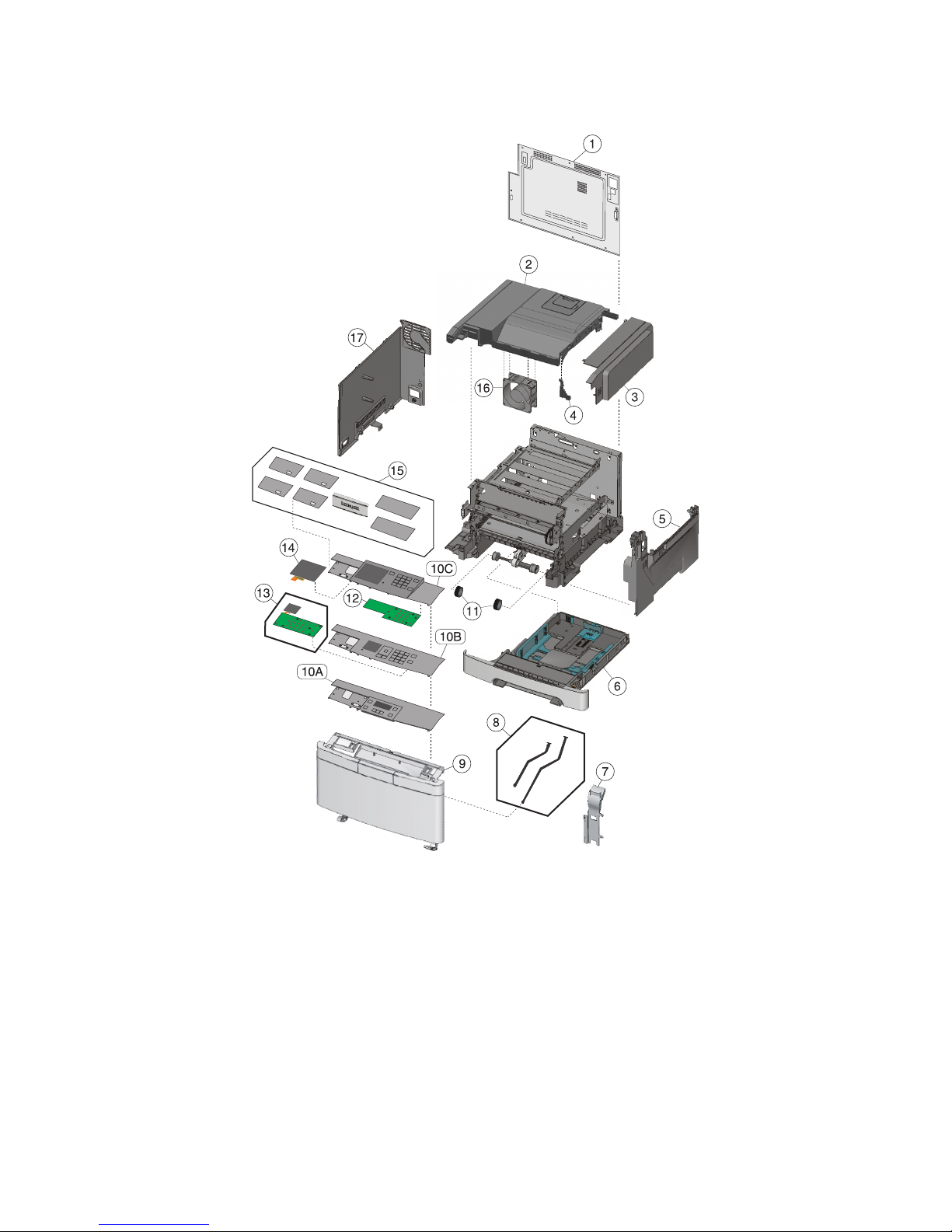
Assembly 1: Covers
5027
Parts catalog
317
Assembly 1: Covers
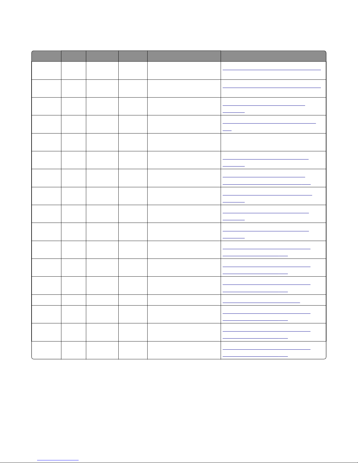
Asm-index P/N Units/mach Units/FRU Description Removal procedure
5027
1‑1 40X7643 1 1 Controller board cover
(CS310, CS410)
1 40X7644 1 1 Controller board cover
(CS510, C2132)
2 40X7633 1 1 Top cover assembly
3 40X7621 1 1 Toner supply door
4 40X9244 1 1 Bracket, front toner door
pivot
5 40X7630 1 1 Right cover assembly
6 40X7645 1 1 250‑sheet tray assembly
7 40X5803 1 1 Duplex reference edge
8 40X7619 2 2 Front cover straps
9 40X7635 1 1 Front cover assembly
“Controller board removal” on page 291
“Controller board removal” on page 291
“Top cover assembly removal” on
page 294
“Toner supply door removal” on page
233
N/A
“Right cover assembly removal” on
page 232
“Paper pick motor drive assembly
standard tray removal” on page 287
“Duplex reference edge removal” on
page 265
“Front cover assembly removal” on
page 252
“Front cover assembly removal” on
page 252
10A 40X7638 1 1 Operator panel and display
assembly (CS310)
10B 40X7640 1 1 Operator panel (CS410)
10C 40X7642 1 1 Operator panel (CS510,
C2132)
11 40X5168 2 2 Pick tires
12 40X7650 1 1 UICC card (CS510, C2132)
13 40X7651 1 1 2.4” Display and UICC card
(CS410)
14 40X7116 1 1 4.3” Display
“Operator panel removal (for CS310
models only)” on page 254
“Operator panel removal (for CS410
models only)” on page 256
“Operator panel removal (for CS510
models only)” on page 259
“Pick tire removal” on page 303
“Operator panel removal (for CS510
models only)” on page 259
“Operator panel removal (for CS410
models only)” on page 256
“Operator panel removal (for CS510
models only)” on page 259
Parts catalog
318
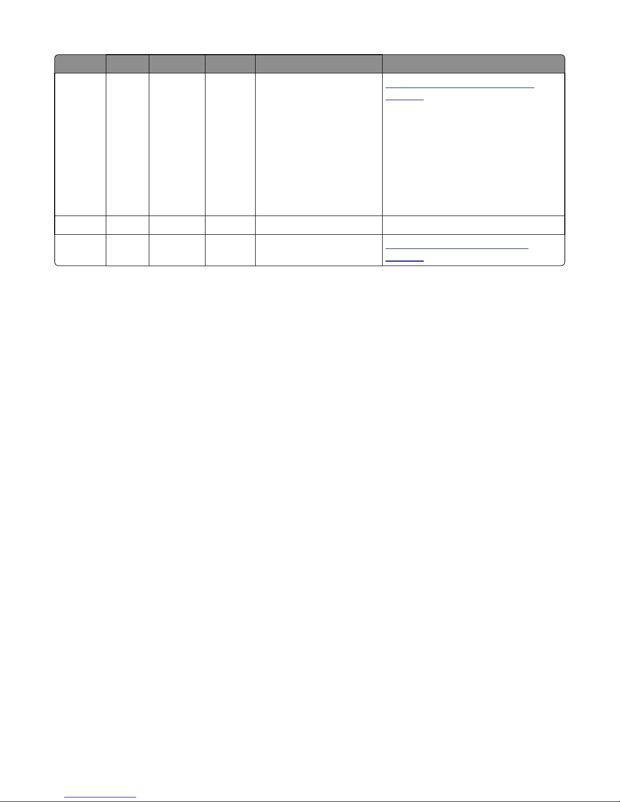
Asm-index P/N Units/mach Units/FRU Description Removal procedure
5027
15 40X7637 1 1 Operator panel bezel and
name plates, including:
“Operator panel bezel removal” on
page 254
• Bezel (1)
• Name plates (4)
• Logo plate (1)
• CS310 cover (1)
• CS310 cover (1)
• CS510 USB cover (1)
• CS510 USB cover (1)
16 40X7579 1 1 System fan N/A
17 40X7632 1 1 Left cover assembly
“Left cover assembly removal” on
page 219
Parts catalog
319

5027
Parts catalog
320
 Loading...