

Page 1

Revised March 24, 2006
Lexmark C510
• Table of Contents
•Start Diagnostics
5021-0XX
• Safety and Notices
• Trademarks
•Index
Lexmark and Lexmark with diamond
design are trademarks of Lexmark
International, Inc., registered in the
United States and/or other countries.
Page 2

5021-0XX
Edition: March 24, 2006
The following paragraph does not apply to any country where such provisions are
inconsistent with local law: LEXMARK INTERNATIONAL, INC. PROVIDES THIS
PUBLICATION “AS IS” WITHOUT WARRANTY OF ANY KIND, EITHER EXPRESS OR
IMPLIED, INCLUDING, BUT NOT LIMITED TO, THE IMPLIED WARRANTIES OF
MERCHANTABILITY OR FITNESS FOR A PARTICULAR PURPOSE. Some states do
not allow disclaimer of express or implied warranties in certain transactions; therefore,
this statement may not apply to you.
This publication could include technical inaccuracies or typographical errors. Changes
are periodically made to the information herein; these changes will be incorporated in
later editions. Improvements or changes in the products or the programs described may
be made at any time.
Comments may be addressed to Lexmark International, Inc., Department D22A/032-2,
740 West New Circle Road, Lexington, Kentucky 40550, U.S.A or electronically mailed
(e-mail) to ServiceInfoAndTraining@Lexmark.com. Lexmark may use or distribute any of
the information you supply in any way it believes appropriate without incurring any
obligation to you.
Lexmark and Lexmark with diamond design are trademarks of Lexmark International,
Inc., registered in the United States and/or other countries.
ImageQuick, Optra Forms, and PrintCryption are trademarks of Lexmark International,
Inc.
PCL® is a registered trademark of the Hewlett-Packard Company.
PostScript® is a registered trademark of Adobe Systems Incorporated.
Other trademarks are the property of their respective owners.
© 2004 Lexmark International, Inc.
All rights reserved.
UNITED STATES GOVERNMENT RIGHTS
This software and any accompanying documentation provided under this agreement are
commercial computer software and documentation developed exclusively at private
expense.
P/N 12G9320
Page 3

5021-0XX
Table of contents
Laser notices. . . . . . . . . . . . . . . . . . . . . . . . . . . . . . . . . . . . . . . . . . . xi
Safety information. . . . . . . . . . . . . . . . . . . . . . . . . . . . . . . . . . . . . . xxi
Preface . . . . . . . . . . . . . . . . . . . . . . . . . . . . . . . . . . . . . . . . . . . . . . xxvi
Definitions . . . . . . . . . . . . . . . . . . . . . . . . . . . . . . . . . . . . . . . . . xxvi
General information . . . . . . . . . . . . . . . . . . . . . . . . . . . . . . . . . . . . 1-1
Maintenance approach . . . . . . . . . . . . . . . . . . . . . . . . . . . . . . . . 1-1
Tools required for service . . . . . . . . . . . . . . . . . . . . . . . . . . . . . . 1-1
Serial number . . . . . . . . . . . . . . . . . . . . . . . . . . . . . . . . . . . . . . . 1-2
Acronyms . . . . . . . . . . . . . . . . . . . . . . . . . . . . . . . . . . . . . . . . . . 1-3
Specifications . . . . . . . . . . . . . . . . . . . . . . . . . . . . . . . . . . . . . . . 1-4
Resolution. . . . . . . . . . . . . . . . . . . . . . . . . . . . . . . . . . . . . . . . 1-4
Model differences . . . . . . . . . . . . . . . . . . . . . . . . . . . . . . . . . . 1-4
Technical specifications . . . . . . . . . . . . . . . . . . . . . . . . . . . . . 1-4
Physical specifications and weight . . . . . . . . . . . . . . . . . . . . . 1-5
Operating clearances . . . . . . . . . . . . . . . . . . . . . . . . . . . . . . . 1-6
Packaging and shipping dimension s. . . . . . . . . . . . . . . . . . . . 1-6
Print speed and performance . . . . . . . . . . . . . . . . . . . . . . . . . 1-7
Time to first print . . . . . . . . . . . . . . . . . . . . . . . . . . . . . . . . . . . 1-7
Duty cycle . . . . . . . . . . . . . . . . . . . . . . . . . . . . . . . . . . . . . . . . 1-8
Printer memory . . . . . . . . . . . . . . . . . . . . . . . . . . . . . . . . . . . . 1-8
Paper and media specifications . . . . . . . . . . . . . . . . . . . . . . . 1-8
Media sizes. . . . . . . . . . . . . . . . . . . . . . . . . . . . . . . . . . . . . . 1-11
Output capacity by media and source. . . . . . . . . . . . . . . . . . 1-12
Media guidelines. . . . . . . . . . . . . . . . . . . . . . . . . . . . . . . . . . 1-12
Connectivity. . . . . . . . . . . . . . . . . . . . . . . . . . . . . . . . . . . . . . 1-14
Power and electrical specifications. . . . . . . . . . . . . . . . . . . . 1-15
Environment . . . . . . . . . . . . . . . . . . . . . . . . . . . . . . . . . . . . . 1-16
Printer identification . . . . . . . . . . . . . . . . . . . . . . . . . . . . . . . . . . 1-17
Options identification . . . . . . . . . . . . . . . . . . . . . . . . . . . . . . . . . 1-18
Printer theory of operation . . . . . . . . . . . . . . . . . . . . . . . . . . . . . 1-19
Printer paper path . . . . . . . . . . . . . . . . . . . . . . . . . . . . . . . . . . . 1-20
Printer systems description . . . . . . . . . . . . . . . . . . . . . . . . . . . . 1-21
Basic principles of color printing . . . . . . . . . . . . . . . . . . . . . . 1-21
Mechanical and electrical structures. . . . . . . . . . . . . . . . . . . 1-21
Printer component systems . . . . . . . . . . . . . . . . . . . . . . . . . 1-23
Basic process of color printing . . . . . . . . . . . . . . . . . . . . . . . 1-24
Print system and transfer system . . . . . . . . . . . . . . . . . . . . . 1-25
Structure of OPC belt (photo developer cartridge) . . . . . . . . 1-26
iii
Page 4

5021-0XX
Basic structure of the print system. . . . . . . . . . . . . . . . . . . . .1-27
Details of the print system . . . . . . . . . . . . . . . . . . . . . . . . . . . . .1-29
Charging process. . . . . . . . . . . . . . . . . . . . . . . . . . . . . . . . . .1-29
Exposing process. . . . . . . . . . . . . . . . . . . . . . . . . . . . . . . . . .1-31
Developing process . . . . . . . . . . . . . . . . . . . . . . . . . . . . . . . .1-32
First transfer (drum) process . . . . . . . . . . . . . . . . . . . . . . . . .1-34
Belt discharge (erase lamp) process . . . . . . . . . . . . . . . . . . .1-35
Belt cleaning process. . . . . . . . . . . . . . . . . . . . . . . . . . . . . . .1-36
Details of the transfer system . . . . . . . . . . . . . . . . . . . . . . . . . . .1-38
Second transfer (paper) process . . . . . . . . . . . . . . . . . . . . . .1-38
Transfer belt cleaning process. . . . . . . . . . . . . . . . . . . . . . . .1-39
Details of the optical system . . . . . . . . . . . . . . . . . . . . . . . . . . . .1-40
Details of the paper transportation system . . . . . . . . . . . . . . . . .1-42
Fusing unit . . . . . . . . . . . . . . . . . . . . . . . . . . . . . . . . . . . . . . .1-44
Fusing process. . . . . . . . . . . . . . . . . . . . . . . . . . . . . . . . . . . .1-46
Control system structure . . . . . . . . . . . . . . . . . . . . . . . . . . . . . .1-47
Electrical system and function . . . . . . . . . . . . . . . . . . . . . . . .1-47
Control of print process . . . . . . . . . . . . . . . . . . . . . . . . . . . . .1-48
Print sequence diagram . . . . . . . . . . . . . . . . . . . . . . . . . . . .1-49
Laser drive control circuit. . . . . . . . . . . . . . . . . . . . . . . . . . . .1-50
Interface control . . . . . . . . . . . . . . . . . . . . . . . . . . . . . . . . . . .1-51
Diagnostic information . . . . . . . . . . . . . . . . . . . . . . . . . . . . . . . . . .2-1
Start . . . . . . . . . . . . . . . . . . . . . . . . . . . . . . . . . . . . . . . . . . . . . . .2-1
Service error codes . . . . . . . . . . . . . . . . . . . . . . . . . . . . . . . . . . .2-2
Operator messages . . . . . . . . . . . . . . . . . . . . . . . . . . . . . . . . . . .2-9
Paper jam messages . . . . . . . . . . . . . . . . . . . . . . . . . . . . . . . . .2-22
Symptom tables . . . . . . . . . . . . . . . . . . . . . . . . . . . . . . . . . . . . .2-25
Printer symptom table . . . . . . . . . . . . . . . . . . . . . . . . . . . . . .2-25
Print quality symptom table . . . . . . . . . . . . . . . . . . . . . . . . . .2-27
Printer service checks . . . . . . . . . . . . . . . . . . . . . . . . . . . . . . . .2-29
901—Yellow developer clutch service check. . . . . . . . . . . . .2-29
902—Magenta developer clutch service check . . . . . . . . . . .2-31
903—Cyan developer clutch service check . . . . . . . . . . . . .2-33
904—Black developer clutch service check . . . . . . . . . . . . .2-35
905—Yellow toner retract solenoid service check . . . . . . . . .2-37
906—Magenta toner retract solenoid service check . . . . . . .2-39
907—Cyan toner retract solenoid service check . . . . . . . . . .2-41
908—Black toner retract solenoid service check. . . . . . . . . .2-43
910—Developer motor service check . . . . . . . . . . . . . . . . . .2-45
911—Main motor service check. . . . . . . . . . . . . . . . . . . . . . .2-48
912—Power supply fan service check . . . . . . . . . . . . . . . . . .2-51
913—Fuser fan service check . . . . . . . . . . . . . . . . . . . . . . . .2-52
iv Service Manual
Page 5

5021-0XX
914—Laser fan service check. . . . . . . . . . . . . . . . . . . . . . . . 2-53
915—Erase lamp service check . . . . . . . . . . . . . . . . . . . . . . 2-54
916—Toner empty sensor (sender-TPD) service check. . . . 2-56
917—Toner empty sensor (receiver-TTR) service check. . . 2-57
918—HVPS connection service check . . . . . . . . . . . . . . . . . 2-58
919—Lower feed unit (secondary paper assembly) service check
2-59
920—Fuser thermistor service check . . . . . . . . . . . . . . . . . . 2-60
921,922,923,924,925—Fuser assembly service check . . . . 2-61
930,931,932—Laser unit assembly service check . . . . . . . . 2-62
985—Duplex connection error 1 service check. . . . . . . . . . . 2-63
986—Duplex connection error 2 service check. . . . . . . . . . . 2-64
990—Transfer belt unit service check. . . . . . . . . . . . . . . . . . 2-65
991—Transfer roller clutch service check. . . . . . . . . . . . . . . 2-67
992—Transfer belt cleaning roller clutch service check . . . . 2-68
993—Fuser clutch service check . . . . . . . . . . . . . . . . . . . . . 2-69
994—OPC belt marker sensor service check. . . . . . . . . . . . 2-70
995—High voltage power supply (HVPS) service check . . . 2-72
996—Low voltage power supply (LVPS) service check . . . . 2-74
Cover open service check. . . . . . . . . . . . . . . . . . . . . . . . . . . 2-75
Incorrect media service check. . . . . . . . . . . . . . . . . . . . . . . . 2-78
Missing photodeveloper cartridge service check . . . . . . . . . 2-80
Missing toner cartridge service check. . . . . . . . . . . . . . . . . . 2-81
OPC belt (photodeveloper) cartridge dr iv e service check . . 2-83
Operator panel service check . . . . . . . . . . . . . . . . . . . . . . . . 2-84
Output tray full service check . . . . . . . . . . . . . . . . . . . . . . . . 2-85
Paper size sensing service check. . . . . . . . . . . . . . . . . . . . . 2-87
Printer no power service check. . . . . . . . . . . . . . . . . . . . . . . 2-89
Toner feed service check . . . . . . . . . . . . . . . . . . . . . . . . . . . 2-91
Toner low/empty service check. . . . . . . . . . . . . . . . . . . . . . . 2-92
Transfer roller missing service check . . . . . . . . . . . . . . . . . . 2-93
Tray empty service check . . . . . . . . . . . . . . . . . . . . . . . . . . . 2-95
Waste toner bottle service check . . . . . . . . . . . . . . . . . . . . . 2-97
Waste toner feed service check . . . . . . . . . . . . . . . . . . . . . . 2-98
Paper feed service checks . . . . . . . . . . . . . . . . . . . . . . . . . . . . 2-99
Printer paper feed service check . . . . . . . . . . . . . . . . . . . . . 2-99
Print quality service checks . . . . . . . . . . . . . . . . . . . . . . . . . . . 2-101
Background service check . . . . . . . . . . . . . . . . . . . . . . . . . 2-101
Back stain service check . . . . . . . . . . . . . . . . . . . . . . . . . . 2-102
Banding service check . . . . . . . . . . . . . . . . . . . . . . . . . . . . 2-103
Black line service check . . . . . . . . . . . . . . . . . . . . . . . . . . . 2-104
Color misregistration service check . . . . . . . . . . . . . . . . . . 2-105
Insufficient fusing service check . . . . . . . . . . . . . . . . . . . . . 2-107
v
Page 6

5021-0XX
Insufficient gloss service check . . . . . . . . . . . . . . . . . . . . . .2-108
Jitter service check . . . . . . . . . . . . . . . . . . . . . . . . . . . . . . .2-109
Missing image at edge service check . . . . . . . . . . . . . . . . .2-110
Mixed color image service check . . . . . . . . . . . . . . . . . . . .2-111
Mottle service check . . . . . . . . . . . . . . . . . . . . . . . . . . . . . .2-112
Residual image service check . . . . . . . . . . . . . . . . . . . . . . .2-113
Ribbing service check . . . . . . . . . . . . . . . . . . . . . . . . . . . . .2-114
Toner drop service check . . . . . . . . . . . . . . . . . . . . . . . . . .2-116
Vertical line service check . . . . . . . . . . . . . . . . . . . . . . . . . .2-118
Vertical staggering image service check . . . . . . . . . . . . . . .2-119
Vertical white band service check . . . . . . . . . . . . . . . . . . . .2-120
White band service check . . . . . . . . . . . . . . . . . . . . . . . . . .2-121
White line I service check . . . . . . . . . . . . . . . . . . . . . . . . . .2-122
White line II service check . . . . . . . . . . . . . . . . . . . . . . . . . .2-123
White spot / black spot service check . . . . . . . . . . . . . . . . .2-124
White print service check . . . . . . . . . . . . . . . . . . . . . . . . . .2-125
Wrinkle / image migration service check . . . . . . . . . . . . . . .2-126
Uneven density (right and left). . . . . . . . . . . . . . . . . . . . . . .2-127
Spacing table . . . . . . . . . . . . . . . . . . . . . . . . . . . . . . . . . . . . . .2-129
Roller specifications . . . . . . . . . . . . . . . . . . . . . . . . . . . . . .2-129
Diagnostic aids . . . . . . . . . . . . . . . . . . . . . . . . . . . . . . . . . . . . . . . .3-1
Disabling download emulations . . . . . . . . . . . . . . . . . . . . . . . . . .3-1
Paper jam sequence . . . . . . . . . . . . . . . . . . . . . . . . . . . . . . . . . .3-2
Diagnostic mode . . . . . . . . . . . . . . . . . . . . . . . . . . . . . . . . . . . . . .3-4
Diagnostics menu structure . . . . . . . . . . . . . . . . . . . . . . . . . . .3-5
Print quality test pages. . . . . . . . . . . . . . . . . . . . . . . . . . . . . . .3-5
Print registration . . . . . . . . . . . . . . . . . . . . . . . . . . . . . . . . . . . . . .3-6
Setting tray 2 left margin . . . . . . . . . . . . . . . . . . . . . . . . . . . . .3-6
Setting top margin . . . . . . . . . . . . . . . . . . . . . . . . . . . . . . . . . .3-7
Print tests . . . . . . . . . . . . . . . . . . . . . . . . . . . . . . . . . . . . . . . . . . .3-7
Hardware tests . . . . . . . . . . . . . . . . . . . . . . . . . . . . . . . . . . . . . . .3-8
LCD test . . . . . . . . . . . . . . . . . . . . . . . . . . . . . . . . . . . . . . . . . .3-9
Button test . . . . . . . . . . . . . . . . . . . . . . . . . . . . . . . . . . . . . . . .3-9
Parallel wrap test . . . . . . . . . . . . . . . . . . . . . . . . . . . . . . . . . . .3-9
ROM memory test . . . . . . . . . . . . . . . . . . . . . . . . . . . . . . . . .3-10
DRAM memory test . . . . . . . . . . . . . . . . . . . . . . . . . . . . . . . .3-11
Serial wrap test. . . . . . . . . . . . . . . . . . . . . . . . . . . . . . . . . . . .3-11
Duplex tests . . . . . . . . . . . . . . . . . . . . . . . . . . . . . . . . . . . . . . . .3-13
Duplex left margin . . . . . . . . . . . . . . . . . . . . . . . . . . . . . . . . .3-13
Device tests . . . . . . . . . . . . . . . . . . . . . . . . . . . . . . . . . . . . . . . .3-14
Quick disk test . . . . . . . . . . . . . . . . . . . . . . . . . . . . . . . . . . . .3-14
Disk test/clean . . . . . . . . . . . . . . . . . . . . . . . . . . . . . . . . . . . .3-14
vi Service Manual
Page 7

5021-0XX
Flash test. . . . . . . . . . . . . . . . . . . . . . . . . . . . . . . . . . . . . . . . 3-15
Printer setup . . . . . . . . . . . . . . . . . . . . . . . . . . . . . . . . . . . . . . . 3-16
Setting the page count . . . . . . . . . . . . . . . . . . . . . . . . . . . . . 3-16
Viewing the permanent page count. . . . . . . . . . . . . . . . . . . . 3-16
Serial number . . . . . . . . . . . . . . . . . . . . . . . . . . . . . . . . . . . . 3-17
Setting configuration ID. . . . . . . . . . . . . . . . . . . . . . . . . . . . . 3-17
Parallel strobe adjustment. . . . . . . . . . . . . . . . . . . . . . . . . . . 3-18
Error log . . . . . . . . . . . . . . . . . . . . . . . . . . . . . . . . . . . . . . . . . . 3-19
Viewing the error log. . . . . . . . . . . . . . . . . . . . . . . . . . . . . . . 3-19
Printing the error log . . . . . . . . . . . . . . . . . . . . . . . . . . . . . . . 3-19
Clearing the error log . . . . . . . . . . . . . . . . . . . . . . . . . . . . . . 3-20
Restore EP factory defaults . . . . . . . . . . . . . . . . . . . . . . . . . 3-20
Exiting diagnostic mode . . . . . . . . . . . . . . . . . . . . . . . . . . . . . . 3-21
Repair information . . . . . . . . . . . . . . . . . . . . . . . . . . . . . . . . . . . . . 4-1
Removal and cleaning precautions . . . . . . . . . . . . . . . . . . . . . . . 4-1
Handling the printed circuit boards with
MOS ICs . . . . . . . . . . . . . . . . . . . . . . . . . . . . . . . . . . . . . . . . . . . 4-2
During transportation/storage:. . . . . . . . . . . . . . . . . . . . . . . . . 4-2
During replacement: . . . . . . . . . . . . . . . . . . . . . . . . . . . . . . . . 4-2
During inspection:. . . . . . . . . . . . . . . . . . . . . . . . . . . . . . . . . . 4-2
Photodeveloper cartridge . . . . . . . . . . . . . . . . . . . . . . . . . . . . . . 4-3
During transportation/storage . . . . . . . . . . . . . . . . . . . . . . . . . 4-3
Handling . . . . . . . . . . . . . . . . . . . . . . . . . . . . . . . . . . . . . . . . . 4-3
Parts not to be touched. . . . . . . . . . . . . . . . . . . . . . . . . . . . . . 4-3
Printer removal procedures . . . . . . . . . . . . . . . . . . . . . . . . . . . . . 4-4
Precautions to take before maintenance work . . . . . . . . . . . . 4-4
CRU/FRU and supplies removals . . . . . . . . . . . . . . . . . . . . . . . . 4-5
Cleaning roller cover removal. . . . . . . . . . . . . . . . . . . . . . . . . 4-6
Transfer belt cleaning roller removal. . . . . . . . . . . . . . . . . . . . 4-6
Transfer belt unit removal . . . . . . . . . . . . . . . . . . . . . . . . . . . . 4-7
Transfer roller removal . . . . . . . . . . . . . . . . . . . . . . . . . . . . . . 4-8
Fuser assembly removal. . . . . . . . . . . . . . . . . . . . . . . . . . . . . 4-9
Waste toner bottle removal. . . . . . . . . . . . . . . . . . . . . . . . . . 4-10
Photodeveloper cartridge removal . . . . . . . . . . . . . . . . . . . . 4-11
Duplex unit assembly removal . . . . . . . . . . . . . . . . . . . . . . . 4-13
Secondary paper feed assembly removal. . . . . . . . . . . . . . . 4-16
Cover removals . . . . . . . . . . . . . . . . . . . . . . . . . . . . . . . . . . . . . 4-17
Top cover assembly removal . . . . . . . . . . . . . . . . . . . . . . . . 4-18
Front cover assembly removal . . . . . . . . . . . . . . . . . . . . . . . 4-19
Right cover removal . . . . . . . . . . . . . . . . . . . . . . . . . . . . . . . 4-22
Rear cover assembly removal. . . . . . . . . . . . . . . . . . . . . . . . 4-22
Left cover removal. . . . . . . . . . . . . . . . . . . . . . . . . . . . . . . . . 4-24
vii
Page 8

5021-0XX
Laser unit assembly (printhead) removal. . . . . . . . . . . . . . . .4-24
Laser unit fan assembly removal . . . . . . . . . . . . . . . . . . . . . .4-26
Erase lamp removal . . . . . . . . . . . . . . . . . . . . . . . . . . . . . . . .4-27
Right side removals . . . . . . . . . . . . . . . . . . . . . . . . . . . . . . . . . .4-29
Front door interlock switch removal . . . . . . . . . . . . . . . . . . . .4-29
Front door interlock switch with bracket. . . . . . . . . . . . . . . . .4-31
Developer motor removal. . . . . . . . . . . . . . . . . . . . . . . . . . . .4-31
Waste toner bottle holder removal . . . . . . . . . . . . . . . . . . . . .4-32
Developer drive assembly removal . . . . . . . . . . . . . . . . . . . .4-32
Toner sensor (sender) removal . . . . . . . . . . . . . . . . . . . . . . .4-35
Cleaning roller clutch removal . . . . . . . . . . . . . . . . . . . . . . . .4-36
Main motor assembly removal . . . . . . . . . . . . . . . . . . . . . . . .4-38
Clutch removal . . . . . . . . . . . . . . . . . . . . . . . . . . . . . . . . . . . .4-40
Main drive gear assembly removal. . . . . . . . . . . . . . . . . . . . .4-41
Waste toner feeder removal. . . . . . . . . . . . . . . . . . . . . . . . . .4-42
Rear removals . . . . . . . . . . . . . . . . . . . . . . . . . . . . . . . . . . . . . .4-44
RIP board removal . . . . . . . . . . . . . . . . . . . . . . . . . . . . . . . . .4-45
Bracket assembly removal. . . . . . . . . . . . . . . . . . . . . . . . . . .4-45
Paper guide assembly removal . . . . . . . . . . . . . . . . . . . . . . .4-46
Paper guide (C) assembly removal . . . . . . . . . . . . . . . . . . . .4-47
Paper feed roller removal. . . . . . . . . . . . . . . . . . . . . . . . . . . .4-48
Paper exit assembly removal. . . . . . . . . . . . . . . . . . . . . . . . .4-49
Registration assembly removal . . . . . . . . . . . . . . . . . . . . . . .4-52
Left side removals . . . . . . . . . . . . . . . . . . . . . . . . . . . . . . . . . . .4-53
Operator panel cable removal . . . . . . . . . . . . . . . . . . . . . . . .4-54
Engine controller board removal . . . . . . . . . . . . . . . . . . . . . .4-55
RIP board cage removal. . . . . . . . . . . . . . . . . . . . . . . . . . . . .4-57
High voltage power supply (HVPS) removal . . . . . . . . . . . . .4-59
Low voltage power supply (LVPS) with cage removal . . . . . .4-60
HVPS cage removal. . . . . . . . . . . . . . . . . . . . . . . . . . . . . . . .4-62
Toner present sensor remov al . . . . . . . . . . . . . . . . . . . . . . . .4-63
Toner sensor (receiver) removal . . . . . . . . . . . . . . . . . . . . . .4-64
Toner retract solenoid and cam removal . . . . . . . . . . . . . . . .4-64
Left tray guide assembly removal. . . . . . . . . . . . . . . . . . . . . .4-65
Top removals . . . . . . . . . . . . . . . . . . . . . . . . . . . . . . . . . . . . . . .4-68
Marker sensor assembly removal . . . . . . . . . . . . . . . . . . . . .4-69
I/O board removal. . . . . . . . . . . . . . . . . . . . . . . . . . . . . . . . . .4-70
Waste toner auger removal . . . . . . . . . . . . . . . . . . . . . . . . . .4-72
Waste toner agitator removal . . . . . . . . . . . . . . . . . . . . . . . . .4-73
Power supply fan removal . . . . . . . . . . . . . . . . . . . . . . . . . . .4-74
viii Service Manual
Page 9

5021-0XX
Locations and connectors . . . . . . . . . . . . . . . . . . . . . . . . . . . . . . . 5-1
Printer . . . . . . . . . . . . . . . . . . . . . . . . . . . . . . . . . . . . . . . . . . . 5-1
Options . . . . . . . . . . . . . . . . . . . . . . . . . . . . . . . . . . . . . . . . . . 5-3
Electronic components . . . . . . . . . . . . . . . . . . . . . . . . . . . . . . . . 5-4
Sensor locations . . . . . . . . . . . . . . . . . . . . . . . . . . . . . . . . . . . 5-4
Printer circuit board locations . . . . . . . . . . . . . . . . . . . . . . . . . 5-6
Fan/motor locations . . . . . . . . . . . . . . . . . . . . . . . . . . . . . . . . 5-7
Interlock switch locations . . . . . . . . . . . . . . . . . . . . . . . . . . . . 5-8
Solenoid/clutch locations . . . . . . . . . . . . . . . . . . . . . . . . . . . . 5-9
Symbol and part name table . . . . . . . . . . . . . . . . . . . . . . . . 5-11
Wiring diagram / cable harness reference . . . . . . . . . . . . . . 5-14
RIP board . . . . . . . . . . . . . . . . . . . . . . . . . . . . . . . . . . . . . . . 5-15
Engine controller board . . . . . . . . . . . . . . . . . . . . . . . . . . . . 5-16
Input/output (I/O) board . . . . . . . . . . . . . . . . . . . . . . . . . . . . 5-17
Low voltage power supply (LVPS) board . . . . . . . . . . . . . . . 5-18
High voltage power supply (HVPS) board. . . . . . . . . . . . . . . 5-18
Printer cables . . . . . . . . . . . . . . . . . . . . . . . . . . . . . . . . . . . . . . 5-19
Cable 1 connector assignments . . . . . . . . . . . . . . . . . . . . . . 5-19
Cable 1 connector pin assignments . . . . . . . . . . . . . . . . . . . 5-19
Cable 2 connector assignments . . . . . . . . . . . . . . . . . . . . . . 5-22
Cable 2 connector pin assignments . . . . . . . . . . . . . . . . . . . 5-22
Cable 3 connector assignments . . . . . . . . . . . . . . . . . . . . . . 5-24
Cable 3 connector pin assignments . . . . . . . . . . . . . . . . . . . 5-24
Cable 4 connector assignments . . . . . . . . . . . . . . . . . . . . . . 5-26
Cable 5 connector assignments . . . . . . . . . . . . . . . . . . . . . . 5-27
Cable 6 connector assignments . . . . . . . . . . . . . . . . . . . . . . 5-32
Cable 6 connector pin assignments . . . . . . . . . . . . . . . . . . . 5-32
Cable 7 connector assignments . . . . . . . . . . . . . . . . . . . . . . 5-36
Cable 7 connector pin assignments . . . . . . . . . . . . . . . . . . . 5-36
Cable 9 connector assignments . . . . . . . . . . . . . . . . . . . . . . 5-42
Cable 9 connector pin assignments . . . . . . . . . . . . . . . . . . . 5-42
Cable 10 connector assignments . . . . . . . . . . . . . . . . . . . . . 5-44
Cable 10 connector pin assignments . . . . . . . . . . . . . . . . . . 5-44
Cable 11 connector assignments . . . . . . . . . . . . . . . . . . . . . 5-46
Cable 11 connector pin assignments . . . . . . . . . . . . . . . . . . 5-46
Cable 12 connector assignments . . . . . . . . . . . . . . . . . . . . . 5-47
Cable 12 connector pin assignments . . . . . . . . . . . . . . . . . . 5-47
Cable 13 connector assignments . . . . . . . . . . . . . . . . . . . . . 5-48
Cable 13 connector pin assignments . . . . . . . . . . . . . . . . . . 5-48
ix
Page 10

5021-0XX
Preventive maintenance . . . . . . . . . . . . . . . . . . . . . . . . . . . . . . . . .6-1
Parts catalog . . . . . . . . . . . . . . . . . . . . . . . . . . . . . . . . . . . . . . . . . .7-1
How to use this parts catalog . . . . . . . . . . . . . . . . . . . . . . . . . . . .7-1
Index . . . . . . . . . . . . . . . . . . . . . . . . . . . . . . . . . . . . . . . . . . . . . . . . . I-1
Part number index . . . . . . . . . . . . . . . . . . . . . . . . . . . . . . . . . . . . . . I-5
x Service Manual
Page 11

Laser notices
The following laser notice labels may be affixed to this printer as
shown:
Laser advisory label
5021-0XX
Laser notices xi
Page 12
5021-0XX
Class 1 Laser statement label
xii Service Manual
Page 13

5021-0XX
Laser notice
The printer is certified in the U.S. to conform to the requirements of
DHHS 21 CFR Subchapter J for Class I (1) laser products, and
elsewhere is certified as a Class I laser product conforming to the
requirements of IEC 60825-1.
Class I laser products are not considered to be hazardous. The
printer contains internally a Class IIIb (3b) laser that is nominally a 5
milliwatt gallium arsenide laser operating in the wa velength region of
770-795 nanometers. The laser system and printer are designed so
there is never any human access to laser radiation above a Class I
level during normal operation, user maint enance, or prescribed
service condition.
Laser
Der Drucker erfüllt gemäß amtlicher Bestätigung der USA die
Anforderungen der Bestimmung DHHS (Department of Health and
Human Services) 21 CFR Teil J für Laserprodukte der Klasse I (1).
In anderen Ländern gilt der Drucker als Laserprodukt der Klasse I,
der die Anforderungen der IEC (International Electrotechnical
Commission) 60825-1 gemäß amtlicher Bestätigung erfüllt.
Laserprodukte der Klasse I gelten als unschädlich. Im Inneren des
Druckers befindet sich ein Laser der Klasse IIIb (3b), bei dem es
sich um einen Galliumarsenlaser mit 5 Milliwatt handelt, der Wellen
der Länge 770-795 Nanometer ausstr ahlt. Das Lasersystem und der
Drucker sind so konzipiert, daß im Normalbetrieb, bei der Wartung
durch den Benutzer oder bei ordnungsgemäßer Wartung durch den
Kundendienst Laserbestr ahlung, die die Klasse I übersteigen würde,
Menschen keinesfalls erreicht.
Laser notices xiii
Page 14

5021-0XX
Avis relatif à l’utilisation de laser
Pour les Etats-Unis : cette imprimante est certifiée conforme aux
provisions DHHS 21 CFR alinéa J concernant les produits laser de
Classe I (1). Pour les autres pays : cette imprimante répond aux
normes IEC 60825-1 relatives aux produits laser de Classe I.
Les produits laser de Classe I sont considérés comme des produits
non dangereux. Cette imprimante est équipée d’un laser de Classe
IIIb (3b) (arséniure de gallium d’une puissance nominale de 5
milliwatts) émettant sur des longueurs d’onde comprises entre 770
et 795 nanomètres. L’imprimante et son système laser sont conçus
pour impossible, dans des conditions normales d’utilisation,
d’entretien par l’utilisateur ou de révision, l’exposition à des
rayonnements laser supérieurs à des rayonnements de Classe I .
Avvertenze sui prodotti laser
Questa stampante è certificata negli Stati Uniti per essere conforme
ai requisiti del DHHS 21 CFR Sottocapitolo J per i prodotti laser di
classe 1 ed è certificata negli altri Paesi come prodotto laser di
classe 1 conforme ai requisiti della norma CEI 60825-1.
I prodotti laser di classe non sono considerati pericolosi. La
stampante contiene al suo interno un laser di classe IIIb (3b)
all’arseniuro di gallio della potenza di 5mW che opera sulla
lunghezza d’onda compresa tra 770 e 795 nanometri. Il sistema
laser e la stampante sono stati progettati in modo tale che le
persone a contatto con la stampante, durante il normale
funzionamento, le operazioni di servizio o quelle di assistenza
tecnica, non ricevano radiazioni laser superiori al livello della classe
1.
xiv Service Manual
Page 15

5021-0XX
Avisos sobre el láser
Se certifica que, en los EE.UU., esta impresora cumple los
requisitos para los productos láser de Clase I (1) establecidos en el
subcapítulo J de la norma CFR 21 del DHHS (Departamento de
Sanidad y Servicios) y, en los demás países, reúne todas las
condiciones expuestas en la norma IEC 60825-1 para pr oductos
láser de Clase I (1).
Los productos láser de Clase I no se consideran peligrosos. La
impresora contiene en su interior un láser de Clase IIIb (3b) de
arseniuro de galio de funcionamiento nominal a 5 milivatios en una
longitud de onda de 770 a 795 nanómetros. El sistema láser y la
impresora están diseñados de forma que ninguna persona pueda
verse af ectada por ning ún tipo de radiaci ón láser superior al nivel de
la Clase I durante su uso normal, el mantenimiento realizado por el
usuario o cualquier otra situación de servicio técnico.
Declaração sobre Laser
A impressora está certificada nos E.U.A. em conformidade com os
requisitos da regulamentação DHHS 21 CFR Subcapítulo J para a
Classe I (1) de produtos laser. Em outros locais, está certificada
como um produto laser da Classe I, em conformidade com os
requisitos da norma IEC 60825-1.
Os produtos laser da Classe I não são considerados perigosos.
Internamente, a impressora contém um pr oduto laser da Classe IIIb
(3b), designado laser de arseneto de potássio, de 5 milliwatts
,operando numa faixa de comprimento de onda entre 770 e 795
nanómetros. O sistema e a impressora laser foram concebidos de
forma a nunca existir qualquer possiblidade de acesso humano a
radiação laser superior a um nível de Classe I durante a operação
normal, a manutenção feita pelo utilizador ou condições de
assistência prescritas.
Laser notices xv
Page 16

5021-0XX
Laserinformatie
De printer voldoet aan de eisen die gesteld worden aan een
laserprodukt van klasse I. Voor de Verenigde Staten zijn deze eisen
vastgelegd in DHHS 21 CFR Subchapter J, voor andere landen in
IEC 60825-1.
Laserprodukten van klasse I worden niet als ongevaarlijk
aangemerkt. De printer is voorzien van een la ser van klasse IIIb
(3b), dat wil zeggen een gallium arsenide-laser van 5 milliwatt met
een golflengte van 770-795 nanometer. Het lasergedeelte en de
printer zijn zo ontworpen dat bij normaal gebruik, bij onderhoud of
reparatie conform de voorschriften, nooit blootstelling mogelijk is
aan laserstraling boven een niveau zoals voorgeschreven is voor
klasse 1.
Lasermeddelelse
Printeren er godkendt som et Klasse I-laserprodukt, i
overenstemmelse med kravene i IEC 60825-1.
Klasse I-laserprodukter betragtes ikke som farlige. Printeren
indeholder internt en Klasse IIIB (3b)-laser, der nominelt er en 5
milliwatt galliumarsenid laser, som arbejder på bølgelængdeområdet
770-795 nanometer. Lasersystemet og printeren er udformet
således, at mennesker aldrig udsættes f or en laserstråling over
Klasse I-niveau ved normal drift, brugervedligeholdelse eller
obligatoriske servicebetingelser.
xvi Service Manual
Page 17

5021-0XX
Huomautus laserlaitteesta
Tämä kirjoitin on Yhdysvalloissa luokan I (1) laserlaitteiden DHHS
21 CFR Subchapter J -määrityksen mukainen ja muualla luokan I
laserlaitteiden IEC 60825-1 -määrityksen mukainen.
Luokan I laserlaitteiden ei katsota olevan vaarallisia käyttäjälle.
Kirjoittimessa on sisäinen luokan IIIb (3b) 5 milliwatin
galliumarsenidilaser, joka toimii aaltoalueella 770 - 795 nanometriä.
Laserjärjestelmä ja kirjoitin on suunniteltu siten, että käyttäjä ei
altistu luokan I määrityksiä voimakkaammalle säteilylle kirjoittimen
normaalin toiminnan, käyttäjän tekemien huoltotoimie n tai muiden
huoltotoimien yhteydessä.
VARO! Avattaessa ja suojalukitus ohitettaessa olet alttiina
näkymättömälle lasersäteilylle. Älä katso säteeseen.
VARNING! Osynlig laserstrålning när denna del är öppnad och
spärren är urkopplad. Betrakta ej strålen.
Laser-notis
Denna skrivare är i USA certifierad att motsvara krav en i DHHS 21
CFR, underparagraf J för laserprodukter av Klass I (1). I andra
länder uppfyller skrivaren kraven för laserprodukter av Klass I enligt
kraven i IEC 60825-1.
Laserprodukter i Klass I anses ej hälsovådliga. Skrivaren har en
inbyggd laser av Klass IIIb (3b) som består a v en laserenhet av
gallium-arsenid på 5 milliwatt som arbetar i våglängdsområdet 770795 nanometer . Lasersystemet och skrivaren är utf ormade så att det
aldrig finns risk för att någon person utsätts för laserstrålning över
Klass I-nivå vid normal användning, underhåll som utförs av
användaren eller annan föreskriven serviceåtgärd.
Laser notices xvii
Page 18

5021-0XX
Laser-melding
Skriveren er godkjent i USA etter kravene i DHHS 21 CFR,
underkapittel J, for klasse I (1) laserprodukter, og er i andre land
godkjent som et Klasse I-laserprodukt i samsvar med kravene i IEC
60825-1.
Klasse I-laserprodukter er ikke å betrakte som farlige. Skriveren
inneholder internt en klasse IIIb (3b)-laser, som består av en
gallium-arsenlaserenhet som avgir stråling i bølgelengdeområdet
770-795 nanometer. Lasersystemet og skriveren er utformet slik at
personer aldri utsettes for laserstråling ut over klasse I-nivå under
vanlig bruk, vedlikehold som utføres av brukeren, eller foreskrevne
serviceoperasjoner.
Avís sobre el Làser
Segons ha estat certificat als Estats Units, aquesta impressora
compleix els requisits de DHHS 21 CFR, apartat J, pels productes
làser de classe I (1), i segons ha estat certificat en altres llocs, és un
producte làser de classe I que compleix els requisits d’IEC 60825-1.
Els productes làser de classe I no es consideren perillosos. Aquesta
impressora conté un làser de classe IIIb (3b) d’arseniür de gal.li,
nominalment de 5 mil.liwats, i funciona a la regió de longitud d’ona
de 770-795 nanòmetres. El sistema làser i la impressora han sigut
concebuts de manera que mai hi hagi exposició a la radiació làser
per sobre d’un nivell de classe I durant una operació normal, durant
les tasques de manteniment d’usuari ni durant els serveis que
satisfacin les condicions prescrites.
xviii Service Manual
Page 19
Japanese laser notice
Chinese laser notice
5021-0XX
Laser notices xix
Page 20
5021-0XX
Korean laser notice
xx Service Manual
Page 21

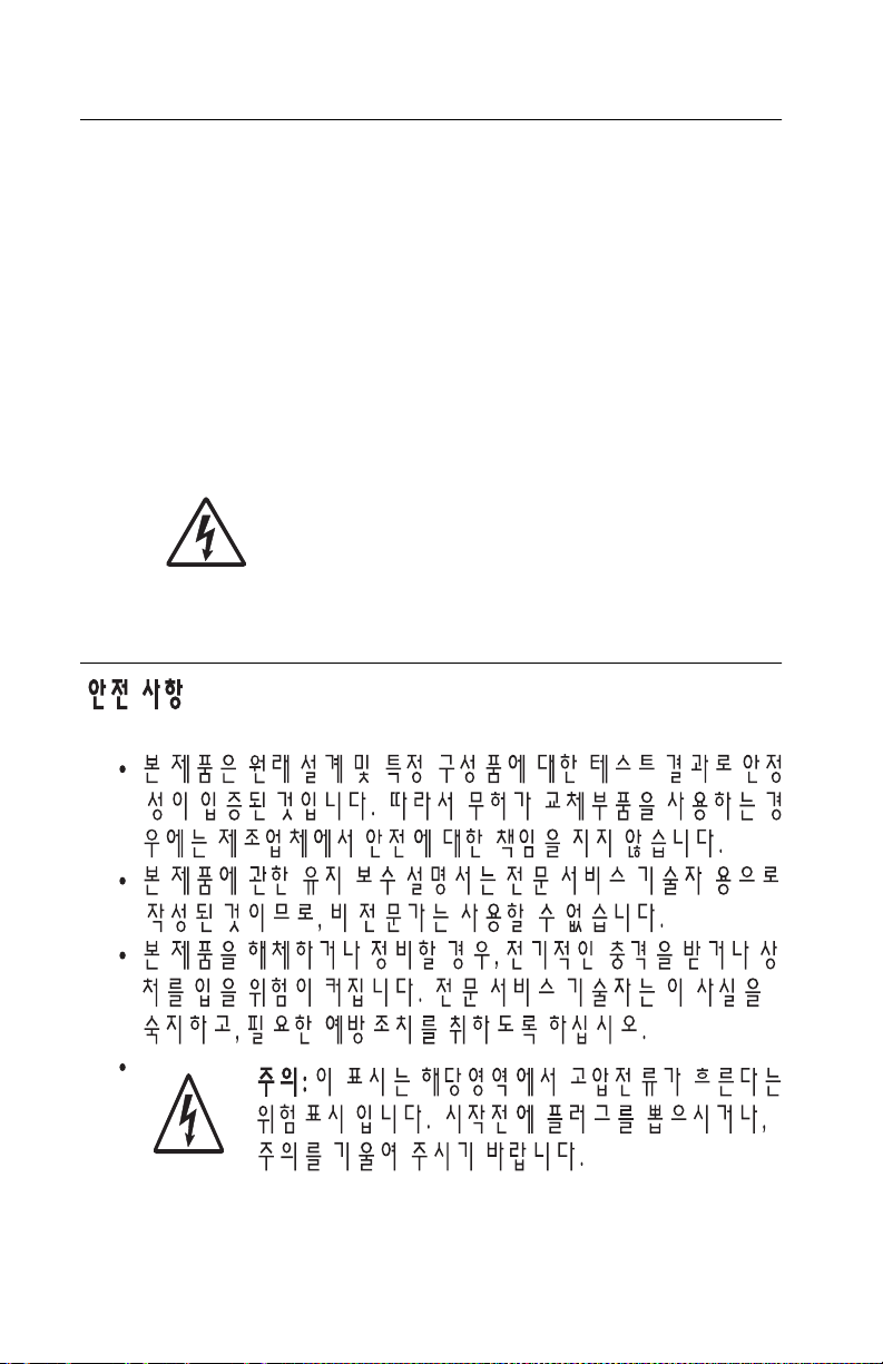
Safety information
• The safety of this product is based on testing and approvals of
the original design and specific components. The manufacturer
is not responsible for safety in the event of use of unauthorized
replacement parts.
• The maintenance information for this product has been
prepared for use by a professional service person and is not
intended to be used by others.
• There may be an increased risk of electric shock and personal
injury during disassembly and servicing of this product.
Professional service personnel should underst and this and tak e
necessary precautions.
• CAUTION: When you see this symbol, there is a
danger from hazardous voltage in the area of the
product where you are working. Unplug the product
before you begin, or use caution if the product must
receive power in order to perform the task.
Consignes de sécurité
5021-0XX
• La sécurité de ce produit repose sur des tests et des
agréations portant sur sa conception d'origine et sur des
composants particuliers. Le fabricant n'assume aucune
responsabilité concernant la sécurité en cas d'utilisation de
pièces de rechange non agréées.
• Les consignes d'entretien et de réparation de ce produit
s'adressent uniquement à un personnel de maintenance
qualifié.
• Le démontage et l'entretien de ce produit pouvant présenter
certains risques électriques, le person n el d'ent re tie n qualif i é
devra prendre toutes les précautions nécessaires.
• ATTENTION : Ce symbole indique la présence
d'une tension dangereuse dans la partie du produit
sur laquelle vous travaillez. Débranchez le produit
avant de commencer ou faites preuve de vigilance si
l'exécution de la tâche e xige que le produit reste sous
tension.
Safety information xxi
Page 22

5021-0XX
Norme di sicurezza
• La sicurezza del prodotto si basa sui test e sull'approvazione
del progetto originale e dei componenti specifici. Il produttore
non è responsabile per la sicurezza in caso di sostituzione non
autorizzata delle parti.
• Le informazioni riguardanti la manutenzione di questo prodotto
sono indirizzate soltanto al personale di assistenza autorizzato.
• Durante lo smontaggio e la manutenzione di questo prodotto,
il rischio di subire scosse elettriche e danni alla persona è più
elevato. Il personale di assistenza autorizzato deve, quindi,
adottare le precauzioni necessarie.
• ATTENZIONE: Questo simbolo indica la presenza
di tensione pericolosa nell'area del prodotto.
Scollegare il prodotto prima di iniziare o usare cautela
se il prodotto deve essere alimentato per eseguire
l'intervento.
Sicherheitshinweise
• Die Sicherheit dieses Produkts basiert auf Tests und
Zulassungen des ursprünglichen Modells und bestimmter
Bauteile. Bei Verwendung nicht genehmigter Ersatzteile wird
vom Hersteller keine Verantwortung oder Haftung für die
Sicherheit übernommen.
• Die Wartungsinformationen für dieses Produkt sind
ausschließlich für die Verwendung durch einen
Wartungsfachmann bestimmt.
• Während des Auseinandernehmens un d de r War t u n g de s
Geräts besteht ein zusätzliches Risiko eines elektrischen
Schlags und körper lic her Verletzung. Das zuständige
Fachpersonal sollte entsprechende Vorsichtsmaßnahmen
treffen.
• ACHTUNG: Dieses Symbol weist auf eine
gefährliche elektrische Spannung hin, die in diesem
Bereich des Produkts auftreten kann. Ziehen Sie vor
den Arbeiten am Gerät den Netzstecker des Geräts,
bzw. arbeiten Sie mit großer Vorsicht, wenn das
Produkt für die Ausführung der Arbeiten an den
Strom angeschlossen sein muß.
xxii Service Manual
Page 23

Pautas de Seguridad
• La seguridad de este producto se basa en pruebas y
aprobaciones del diseño original y componentes específicos.
El fabricante no es responsab le de la seguridad en caso de uso
de piezas de repuesto no autorizadas.
• La información sobre el mantenimiento de este producto está
dirigida exclusivamente al personal cualificado de
mantenimiento.
• Existe mayor riesgo de descarga eléctrica y de daños
personales durante el desmontaje y la reparación de la
máquina. El personal cualificado debe ser consciente de este
peligro y tomar las precauciones necesarias.
• PRECAUCIÓN: este símbolo indica que el voltaje
de la parte del equipo con la que está trabajando es
peligroso. Antes de empezar, desenchufe el equipo
o tenga cuidado si, para trabajar con él, debe
conectarlo.
Informações de Segurança
5021-0XX
• A segurança deste produto baseia-se em testes e aprovações
do modelo original e de componentes específicos. O fabricante
não é responsável pela segunrança, no caso de uso de peças
de substituição não autorizadas.
• As informações de segurança relativas a este produto
destinam-se a profissionais destes serviços e não devem ser
utilizadas por outras pessoas.
• Risco de choques eléctricos e ferimentos gr aves durante a
desmontagem e manutenção deste produto. Os profissionais
destes serviços devem estar avisados deste facto e tomar os
cuidados necessários.
• CUIDADO: Quando vir este símbolo, existe a
possível presença de uma potencial tensão perigosa
na zona do produto em que está a trabalhar. Antes
de começar , desligue o produto da tomada eléctrica
ou seja cuidadoso caso o produto tenha de estar
ligado à corrente eléctrica para realizar a tarefa
necessária.
Safety information xxiii
Page 24
5021-0XX
Informació de Seguretat
• La seguretat d'aquest producte es basa en l'avaluació i
aprovació del disseny original i els components específics.
El fabricant no es fa responsable de les qüestions de
seguretat si s'utilitzen peces de recanvi no autoritzades.
• La informació pel manteniment d’aquest producte està
orientada exclusivament a professionals i no està destinada
a ningú que no ho sigui.
• El risc de xoc elèctric i de danys personals pot augmentar
durant el procés de desmunt atge i de servei d’aquest producte.
El personal professional ha d’estar-ne assabentat i prendre
les mesures convenients.
• PRECAUCIÓ: aquest símbol indica que el voltatge
de la part de l'equip amb la qual esteu treballant és
perillós. Abans de començar, desendolleu l'equip
o extremeu les precaucions si, per treballar amb
l'equip, l'heu de connectar.
xxiv Service Manual
Page 25
5021-0XX
Safety information xxv
Page 26

5021-0XX
Preface
This manual contains maintenance procedures for service
personnel. It is divided into the following chapters:
1. General information contains a general description of the
printer and the maintenance approach used to repair it. Special
tools and test equipment are listed, as well as general
environmental and safety instructions.
2. Diagnostic information contains an error indicator table,
symptom tables, and service checks used to isolate failing field
replaceable units (FRUs).
3. Diagnostic aids contains tests and checks used to locate or
repeat symptoms of printer pr oblems.
4. Repair information provides instructions for making printer
adjustments and removing and installing FRUs.
5. Connector locations uses illustrations to identify the connector
locations and test points on the printer.
6. Preventive maintenance contains the lubrication specifications
and recommendations to prevent problems.
7. Parts catalog contains illustrations and part numbers for
individual FRUs.
Definitions
Note: A note provides additional information.
Warning: A warning identifies something that might damage the
product hardware or software.
CAUTION: A caution identifies something that might cause a
servicer harm.
CAUTION: When you see this symbol, there is a
danger from hazardous voltage in the area of the
product where you are working. Unplug the product
before you begin, or use caution if the product must
receive power in order to perform the task.
xxvi Service Manual
Page 27

5021-0XX
1. General information
This Lexmark™ C510 color laser printer is the ideal printer for
presentations, busin ess graphics, line art, and text. It uses laser
diode electrophotographic technology to deliver remarkable quality
print images and text. The printer can be used as a shared network
or desktop printer.
Maintenance approach
The diagnostic information in this manual leads you to the correct
field replaceable unit (FRU) or part. Use the error code charts,
symptom index, and service checks to determine the symptom and
repair the failure. See “Diagnostic information” on page 2-1, for
location of each section. You may find that the removals in the
Repair information chapter will help you identify parts. After you
complete the repair, perform tests as needed to verify the rep air.
Tools required for service
The removal and adjustment procedures described in this manual
require the following tools and equipment:
• Analog volt ohmmeter (a digital volt ohmmeter may also be
used)
• Flat-blade screwdrivers
• Needle nose pliers
• #1 Phillips screwdriver
• #2 Phillips screwdriver
• Slotted screwdriver #1
• Slotted clock screwdriver #1
• Tweezers, C-ring pliers
When you make voltage readings, always use frame ground unless
another ground is specified.
General information 1-1
Page 28
5021-0XX
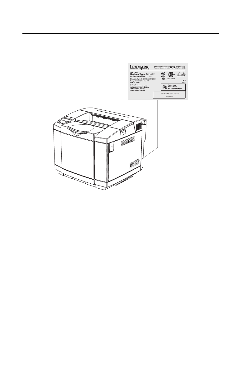
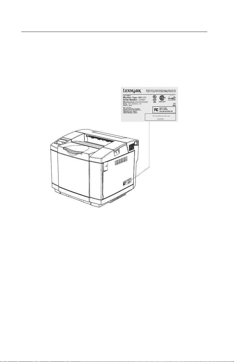
Serial number
Look for the label on the rear cover of your printer for serial number
information. The serial number is also listed in the menu settings
page and can be printed from the utilities menu.
1-2 Service Manual
Page 29

Acronyms
ASIC Application-Specific Integrated Circuit
CS Customer Ordered
CSU Customer Setup
DRAM Dynamic Random Access Memory
EEPROM Electrically Erasable Programmable Read-Only
Memory
EP Electrophotographic Process
ESD Electrostatic Discharge
FRU Field Replaceable Unit
HV High Voltage
HVPS High Voltage Power Supply
LAN Local Area Network
LASER Light Amplification by Stimulated Emission of
Radiation
LCD Liquid Crystal Display
LED Light-Emitting Diode
LV Low Voltage
LVPS Low Voltage Power Supply
NVRAM Nonvolatile Random Access Memory
OEM Original Equipment Manufacturer
PICS Problem Isolation Charts
PIXEL Picture Element
POR Power-On Reset
POST Po wer-On Self Test
PQET Print Quality Enhancement Technology
RIP Raster Image Processor
ROS Read-Only Storage
SRAM Static Random Access Memory
UPR Used Parts Replacement
V AC Volts alternating current
VDC Volts direct current
5021-0XX
General information 1-3
Page 30

5021-0XX
Specifications
Resolution
600 x 600 dpi
2400 image quality
Model differences
C510 C510n C510dtn
USB 2.0 X X X
Parallel X
Ethernet X X
Memory (MB) 64 128 128
Options available
530-sheet drawer
(tray 2)
Duplex X X
Hard disk X X X
Technical specifications
XX
Toner darkness
There are five settings to balance print darkness and toner savings.
The higher the setting, the darker the print. The toner darkness
default setting is 4.
The toner darkness setting is available through the operator panel
under the Color Menu, Toner Darkness menu.
Color correction settings
There are three settings to choose the type of color correction to be
applied when printing.
Auto (default): Applies different color correction to each object on
the printed page depending upon the type of object ( te xt, graphics or
image), and how the color for each object is specified.
Off: No color correction is implemented.
1-4 Service Manual
Page 31

5021-0XX
Manual: Allows users to customize color correction output from the
operator panel. Setting selectab le from the driver.
Physical specifications and weight
The following table contains the dimensions and weights for each
printer model and option. This does not include packaging but does
include the print cartridge that ships with the printer.
Width Depth Height Weight
inch inch inch lb
mm mm mm kg
Printers
Lexmark C510
1
19.5 16.5 15.2 67.0
495 420 385 30.3
Lexmark C510n
2
19.5 16.5 15.2 67.0
495 420 385 30.3
Lexmark C510dtn
3
19.5 20.7 23.2 91.0
495 525 590 41.2
Paper options
Duplex unit 14.2 7.1 15.2 11.0
360 180 385 5.0
530-Sheet drawer 18.1 18.5 7.3 13.3
460 470 185 6.0
530-Sheet tray 11.2 14.4 4.5 4.2
285 365 115 1.9
Standard tray 10.8 13.0 2.2 2.2
275 330 55 1.0
Legal tray 10.8 15.9 2.2 2.5
275 405 55 1.1
1
Base model is the base printer with standard 250-sheet input tray and starter
cartridges.
2
Network model is the network-ready printer with standard input tray and starter
cartridges.
3
Duplex network model is the network-ready printer plus duplex option and 530-sheet
input tray.
4
Weight does not include packaging or pubs.
4
General information 1-5
Page 32

5021-0XX
Operating clearances
Printer sides C510 & C510n C510 & C510n
Left side 8 in (203 mm) 8 in (203 mm) 8 in (203 mm) 8 in (203 mm)
Right side 20 in (508 mm) 20 in (508 mm) 20 in (508 mm) 20 in (508 mm)
Front 28 in (711 mm) 28 in (711 mm) 28 in (711 mm) 28 in (711 mm)
Rear 10 in (254 mm) 10 in (254 mm) 14 in (355 mm) 14 in (355 mm)
Top 23 in (584 mm) 29 in (736 mm) 25 in (635 mm) 29 in (736 mm)
with 530-sheet
tray
C510 & C510n
with duplex
unit
C510dtn with
530-sheet tray
Packaging and shipping dimensions
Width Depth Height Weight
Printers
C510 22.6 20.9 22.4 80
C510n 22.6 20.9 22.4 80
C510dtn
Options
Duplex 18.0 20.8 12.0 16.1
530-Sheet drawer 21.9 22.4 10.9 18.7
530-Sheet tray 17.7 15.1 7.9 6.4
250-Sheet tray 13.2 16.2 5.5 3.3
Legal tray 13.2 19.0 5.7 5.5
1
2
1
in in in lb
mm mm mm kg
574 530 570 36.4
574 530 570 36.4
2
23.4 23.6 46.2 112.2
594.36 599.44 1173.48 51.0
456 528 305 7.3
556 570 277 8.5
450 384 200 2.9
335 412 140 1.5
335 483 144 2.5
Includes start-up kit (supplies)
C510dtn ships printer, duplex and 1 tray bundled on a pallet.
1-6 Service Manual
Page 33

5021-0XX
Print speed and performance
Simplex printing Duplex printing
pages/minute) (sides/minute)
Media size Standard tray Standard tray
Letter 30 8 15 4
A4 308154
Legal 16 8 5 4
Transparencies 3 2 N/S N/S
Thick card stock 3 2 N/S N/S
Labels (letter &
A4)
Medium thick card
stock (letter & A4)
Envelopes 5 3 N/S N/S
N/S - Media size not supported in this tray
Note: For media size A4 duplex mode with custom paper sizes, size sensing is
turned off.
53N/SN/S
43N/SN/S
Time to first print
Simplex Duplex
Time from standby mode 13 seconds 19 seconds 19 seconds 27 seconds
Time from power saver
mode
Note: Time to first page (TTFP) is the time from the moment when the host sends the
print signal until the moment the trailing edge of the first page leaves the exit feed rollers .
TTFP is measured using a simple text (single character) page.
Note: Warm up time, 45 seconds maximum, is the time elapsed from when the power is
turned on to when the ready status is reached.
45 seconds 45 seconds 45 seconds 45 seconds
Processor
500 MHz
General information 1-7
Page 34

5021-0XX
Duty cycle
Maximum duty cycle-35,000 pages (one month's usage)
Machine life-120,000 pages/300,000 images
Printer memory
Memory configuration
C510 C510n C510dtn
Standard DRAM 64MB 128MB 128MB
Max DRAM 320MB
Available memory options
Optional 64MB and 128MB SDRAM DIMMs are available.
Flash memory options
Optional 16MB and 32MB DIMMs are available from Lexmark.
Memory and expansion slots
1
100pin DIMM slots (1-2 SDRAM, 1 Flash
PCI Slots (for optional interface cards) 1 1 1
Firmware card slot 1 1 1
User flash card slot 1 1 1
1
Only one Flash card may be installed.
Only one DLE/Firmware card is supported at a time, as well as only one User Flash card
is supported at a time.
)211
C510 C510n C510dtn
Paper and media specifications
Print area
The C510 printable area is up to 4.0 m m (0.158 in.) f rom the top a nd
bottom of the media, and up to 3.0 mm (0.1 18 in.) fr om the left an d
right edges. Any information placed outside this specified printable
area will not print. Note: For envelopes, the printable area is up to
4.0 mm (0.158 in.) of the left and right edge s , and 3.0 mm(0. 118 in .)
of the top and bottom edges.
1-8 Service Manual
Page 35

5021-0XX
Input and output configurations
The following table shows the standard number of input sources and
output destinations, as well as the estimated capacity of each.
Capacity may v a ry and is subject to media specification s and printer
operating environment. The capacities listed are based on plain
paper at 75 g/m
2
.
Sources and capacities C510/C510n C510dtn
Input sources
Number of standard sources 1 2
Number of optional input drawers 1 0
Maximum number of input sources
Standard input
Primary tray 250 250
Second tray 530
Total standard 250 780
Optional input
Optional legal tray 250 250
Optional tray 1 250 250
Optional tray 2 530 530
Number of standard destinations 1 1
Output capacities
Standard output bin capacity (top)
Media up to 20 lb paper 250 250
Other
Duplex unit Yes Standard
1
Optional input drawer is a 530-sheet capacity drawer. Only one optional drawer
may be installed at any time.
2
The printer supports top output (face down) as standard. No additional output
options are available.
3
Includes optional 530-sheet drawer.
Note: All capacities are based on use of 20 lb paper.
1
Input capacities
Output destinations
2
22
3
General information 1-9
Page 36

5021-0XX
Media input types and weights
Source Type Standard
1,2
Paper
(grain long)
Xerographic
or bond
paper
Xerographic
or bond
paper
100%
Cotton
Card stock Index 163 g/m
Index 164- 210
Transparency
3
tray Legal
tray
60-74
g/m
(16-19 lb)
75-120
g/m
32 lb)
75-120
g/m
(24-32 lb)
(90 lb)
g/m
(91-110
lb)
PN
12A5940
PN
530Sheet
tray
Duplex Printer menu Item
Paper
60-74
2
g/m
(16-19 lb)
75-120
2
(20-
g/m2 (2032 lb)
75-120
2
g/m
(24-32 lb)
2
N/A N/A Card stock Normal
N/A N/A Card stock Heavy
2
60-74
2
g/m
Plain paper Light
2
(16-19 lb)
75-120
g/m2 (2032 lb)
75-120
2
g/m
(24-32 lb)
Plain paper Normal
Plain paper Heavy
2
N/A N/A Transparency
type
12A5941
2
Labels
Envelopes 75-90
g/m
N/A N/A Label
N/A N/A Envelope Normal
2
(20-24lb)
1
Punched, embossed, water-marked, perforated, punched, inkjet paper or plastic-
coated media should not be used.
2
Only occasional use of paper labels in an office environment is supported.
3
Only PN 12A5940 and 12A5941 should be used.
Paper
weight
1-10 Service Manual
Page 37

5021-0XX
Media sizes
Media sizes Dimensions Input Output
Standard 250-sheet tray 1
Optional legal tray
Optional 530-sheet tray 2
Optional duplex unit
Standard 250-sheet bin
mm in.
A4 210 x 297 8.27 x 11.7 X X X X X
A5 148 x 210 5.83 x 8.27 X X X
3
JIS B5
Letter 216 x 279.4 8.5 x 11 X X X X X
Legal 216 x 356 8.5 x 14 X X X
Executive 184.2 x 266.7 7.25 x 10.5 X X X X X
Folio 216 x 330 8.5 x 13 X X X
Statement 139.7 x 215.9 5.5 x 8.5 X X X
Universal
1
Standard 250-sheet
letter tray
Optional 250-sheet
legal tray
Optional duplex 148x210 to
Envelope sizes Dimensions Dimensions
9 Envelope
2
COM 10 Envelope 104.8 x 241.3 4.12 x 9.5 X X X
DL Envelope 110 x 220 4.33 x 8.66 X X X
C5 Envelope
B5 Envelope
1
Select Universal when using a non-standard size sheet of print material. The printer
formats the page for the maximum size 8.5 X 14 in.(215.9 X 355.6 mm). Set the actual
size from your software application.
2
Supported through the driver.
3
B5 may be supported in optional tray 1, but size sensing must be turned off.
2
2
182 x 257 7.17 x 10.1 X X X X
XX X X
104.8x210 to
215.9x297
104.8x210 to
215.9x355.6
4.125x8.27 to
8.5x11.7
4.125x8.27 to
8.5x14
5.83x8.27 to
215.9x355.6
8.5x14
98.4x225.4 3.875 x 8.9 X X X
162 x 229 6.38 x 9.01 X X X
176 x 250 6.93 x 9.84 X X X
General information 1-11
Page 38

5021-0XX
Output capacity by media and source
Source Media Capacity Orientation
Standard output
bin (top)¹
Supports all sizes listed in
the "Media sizes" table
250 sheets (20 lb
paper)
50 Transparencies
Collated
Face down
Media guidelines
With the Lexmark C510 print technology, paper designed for use
with xerographic copiers should provide satisfactory print quality and
feed reliability. Other media types may be suitable. We recommend
that users test any particular brand for suitability to their
applications. Refer to the printer User's Reference for additional
media specifications.
Paper
• Rough, highly textured, limp, or pre-curled papers will result in
lower print quality and more frequent paper feed f ailures.
• Colored papers must be able to withstand 338°F ( 170°C) fusing
temperature.
• Preprinted forms and letterheads should be selected using
guidelines in the printer User's Reference. The chemical
process used in preprinting may render some papers unsuitable
for use with the printer.
• Unsuitable papers include punched, embossed, water-marked,
perforated media, any kind of inkjet paper or plastic-coated
paper.
• Recycled paper less than 75 g/m
unacceptable results.
The laser printing process heats paper to high temperatures of
170°C (338°F). Use only paper able to withstand these
temperatures without discoloring, bleeding, or releasing hazardous
emissions. Check with the man ufacturer or vendor to determine
whether the paper you have chosen is acceptable for laser printers.
Envelopes
Should be fed with short edge first, flap down and to the right.
1-12 Service Manual
2
(20 lb) may cause
Page 39

5021-0XX
• If envelope wrinkling occurs, refer to the User's Reference for
correct loading and stacking of envelopes.
• All envelopes should be new, unused, and without damage.
• Envelopes with excessive curl or twist e xceeding 6.0 mm, those
stuck together, those with bent corners or nicked edges, or
those that interlock should not be used.
• Minimum weight: 90 g/m
2
(24 lb).
• The following envelopes should not be used:
– Envelopes with windows, holes, perforations, cutouts, or
deep embossing
– Envelopes with metal clasps, string ties, or metal folding
bars
– Envelopes with e xposed f lap adhesiv e when th e flap is in the
closed position
– Self-seal envelopes
• Under high humidity conditions (over 60%), the env elopes may
seal during printing.
• For best results, print on new 90 g/m
cotton-bond envelope.
2
(24 lb) sulfite or 25%
Transparencies
• Use letter (12A5940) or A4-size (12A5941) sheets only.
• Transparencies are only supported in tray 1 (standard or legal
trays).
Labels
• Labels should be selected using guidelines f ound in the User's
Reference, Complete Printer Reference, or the Card stock &
Label Guide (located at www.lexmark.com), and tested for
acceptability.
• Vinyl labels are not supported.
• Labels are only supported in tray 1 (standard or legal trays).
Glossy Paper
• Use letter (12A5950) or A4-size (12A5951) sheets only.
General information 1-13
Page 40

5021-0XX
• Glossy paper is only supported from tray 1 (standard or legal
trays).
Connectivity
Cables
Personal comput ers
• A parallel printer cable is required for attachment of the printer
and must be ordered separately.
• For serial attachment, optional RS-232C serial interface card
(P/N 11K4602) should be ordered.
• For USB attachment a USB cable is required and must be
ordered separately.
IBM AS/400
• For parallel attachment, a parallel cable is required.
• For serial attachment, optional RS-232C serial interface card
(P/N 11K4602) should be ordered.
• For serial attachment to the IBM AS/400 ASCII Workstation
Controller, refer to the IBM AS/400 ASCII Workstation
Reference and Example manual (SA41-9922) for specific cable
information. The printer require s th e op tio na l RS -2 32 C serial
interface card (P/N 11K4602).
Connections
C510 C510n C510dtn
Standard local connections Parallel & USB 2.0 Ether net & USB
Standard network
connections
Optional local connections RS-232 Serial/Parallel IEEE 1284-C Interface Card
Optional network
connections
N/A 10/100 Base-TX
10/100Base TX Ethernet, Token-Ring, 802.11b
Wireless
2.0
Ethernet
Ethernet & USB
2.0
10/100 Base-TX
Ethernet
1-14 Service Manual
Page 41

5021-0XX
Power and electrical specifications
Printing states C510 C510n C510dtn
Off 0 W O W O W
Average power while printing
Continuous mono printing 550 W 550 W 550 W
Continuous color printing 370 W 370 W 370 W
Power consumption, standby
Power saver on 12 W 13 W 13 W
Power saver off 150 W 150 W 150 W
Maximum current while printing
100 Volts 8.1 A
115 Volts 7.2 A
230 Volts 2.83 A
Average curre nt while printing
100 Volts 6.9 A
115 Volts 5.6 A
230 Volts 3.0 A
General information 1-15
Page 42

5021-0XX
Environment
Environment Specifications
Operating
Air temperature - product operating 10 to 32.5°C (50 to 90.5°F)
Air temperature - product power off 5 to 35°C (41 to 95°F)
Air relative humidity 15 to 80%
Altitude 0 - 2,500 m (0 - 8,200 ft.)
Ship / Storage
Temperature-printer and supplies 0 to 35°C (32 to 95°F)
Relative humidity 10 to 90% RH
Atmospheric pressure 613 to 16057 hPa (460 to 800 mm Hg)
1
Severe High 35 to 40°C (95 to 104°F), Se vere Low -10 to 0°C (14 to 32°F). The period
under severe shall not be deemed to be continuous, but rather a total of such
intermittent periods (48 hours at most for any one period).
1
1-16 Service Manual
Page 43
Printer identification
5021-0XX
General information 1-17
Page 44

5021-0XX
Options identification
1-18 Service Manual
Page 45

Printer theory of operation
The following diagram shows the major parts of the printer and
paper path.
5021-0XX
General information 1-19
Page 46

5021-0XX
Printer paper path
The following illustration shows the paper path and the associated
paper jam messages for jams at specific points in the paper path.
The printer depicted in the illustration has a duplex unit and
secondary paper feed assembly installed:
1-20 Service Manual
Page 47

5021-0XX
Printer systems description
See the illustration “Printer component systems” on page 1-23,
for more information.
Basic principles of color printing
Color printing is made through the subtractive process of combining
the three primary colors: yellow, magenta, and cyan.
Mechanical and electrical structures
This color laser printer consists of five engineering systems: print,
transfer, optical, paper transport, and control system.
Print system
The print system consists of six functional parts located around the
optical photoconductor (OPC) belt and forms a toner image on the
OPC belt: charge, expose, develop, first transfer, discharge, and
clean.
Transfer system
The transfer system consists of three functional parts that transfers
the toner image formed on the transfer belt to paper: transfer belt
unit, second transfer, and cle aning roller.
Optical system
The optical system consists of two functional parts that forms an
electrostatic latent image on the OPC belt using a laser light: optical
unit and scanner motor (SCM).
Paper transport system
The paper transport system consists of five functional parts that
picks up paper from the paper tray, separates the transported paper
from the transfer be lt, and exits it from the printer after fusing the
toner image on the paper: paper tray, transport, fuser, and paper
exit.
General information 1-21
Page 48

5021-0XX
Control system
The control system consists of four control parts and runs the printer
by processing the interface signals transmitted from the computer
and the other printer systems such as the print, transfer , optical, and
transport system: sequence control, laser control, fusing
temperature control, and interface control.
1-22 Service Manual
Page 49

Printer component systems
5021-0XX
General information 1-23
Page 50

5021-0XX
Basic process of color printing
1. This printer has a toner cartridge for each color — yellow,
magenta, cyan, and black.
2. The toner image is developed with primary colors and then
transferred to the transfer belt for color combination.
3. The toner image formed on the tr ansfer belt is transferred to
paper.
4. The toner is fused to the paper by the thermal fuser unit. During
the fusing process, the primary colors mix, yielding the desired
color.
1-24 Service Manual
Page 51

5021-0XX
Print system and transfer system
This illustration shows the basic structure of the print system having
the OPC belt as a main function, and the transfer system including
the transfer belt . A color print is accomplished by actuating each
process in the print system and the transfer system.
General information 1-25
Page 52

5021-0XX
Structure of OPC belt (photo developer cartridge)
The OPC belt consists of a surface layer having an optical
photoconductor (OPC) of organic material, the inner layer consists
of an insulator material (PET), and the aluminum deposit layer in
between. The OPC belt is a main part of the print system.
1-26 Service Manual
Page 53

Basic structure of the print system
The print system process consists of the following:
1. The OPC belt is biased to the -CBV(V) by power supply CBV.
2. The OPC belt is then evenly charged to the negative hig h
voltage by the OPC charging system. The charging system
consists of a charging brush that is biased by power supply
CHV and a discharge roller that is biased by pow er su pply DCV.
3. The developer roller in the toner cartridge is biased to
-DBV(V) by power supply DBV.
4. Frame potential of transfer drum is GND.
5021-0XX
General information 1-27
Page 54

5021-0XX
5. Variation of the OPC belt potential:
a. The OPC belt is biased to -CBV(V).
b. The OPC belt surface is evenly charged to -Vo(V) during the
charging process.
c. During the exposing process , the optical unit emits a laser
beam that strikes the OPC belt surface forming an
electrostatic image. The electrostatic image is at -VR(V)
potential.
d. The negatively charged toner is moved to the OPC belt in
the dev elopment process due to the differe nce between
-VR(V) and -DBV(V). A visible image is the result.
e. The negatively charged toner on the OPC belt is moved to
the transfer belt because the potential GND of the transfer
belt is greater than -VR(V) of the OPC belt.
f. The OPC belt is discharged by the erase lamp radiating on
the OPC belt.
Latent image
-V0
-V0
TEST
-V0
PRINT
-V0
Laser diode
exposing
2
Developer roller
-V0
-V0
OPC belt
0V
-CBV
-CBV
-CBV
-CBV
-CBV
-CBV
Charging
1
OPC belt surface
-V0
Charge brush
-CHV
(-BRV)
-V0
-V0
-V0
-V0
-V0
-V0
-V0
-V0
-VR
Discharge roller
OPC charging system
DCV
-V0
-V0
-V0
-V0
KY
Developing
3
-V0
-V0
-V0
-V0
Toner image
-V0
TEST
PRINT
-V0
M
C
-DBV
-DBV
-V0
-V0
-V0
PRINT
Transfer belt
4
(M)toner
TEST
-CBV
-CBV
-CBV
-CBV
Erase lamp
5
Blade
6
1-28 Service Manual
Page 55

5021-0XX
Details of the print system
Charging process
In the charging process, the OPC belt is evenly charged by the
charger. See “Printer theory of operation” on page 1-19 for
charger unit location.
The charger unit consists of a charg ing brush and a discharge roller.
1. The charge brush charges the OPC belt surface to
-Vo(V) potential. The charge on the surface of the OPC belt is
then smoothed to an even -Vo(V) by the discharge roller.
2. The charger unit controls the grid to a constant v oltage of ZD(V)
for even charging.
General information 1-29
Page 56

5021-0XX
3. Before charging, the OPC belt surface is -CBV(V).
The charger unit evenly charges the OPC belt surface to -Vo(V)
by generating a negative charge.
1-30 Service Manual
Page 57

Exposing process
In the exposing process, the OPC belt surface is exposed to the
laser light which forms an electrostatic latent image.
The luminous source of the laser is a semiconductor laser. See
“Printer theory of operation” on page 1-19 for optical unit
location.
The laser light scans the OPC belt, forming an electrostatic late nt
image.
1. The OPC belt surface is charged to -Vo(V) potential.
a. The laser scans the OPC belt in a rectangular pattern during
forward movement of the OPC belt.
b. High speed switching of the laser matches the transmitted
image data.
c. The charge of the areas radiated by the laser light is
discharged, creating a -VR(V) potential.
d. An electrostatic latent image is formed (invisible) on the
OPC belt.
5021-0XX
General information 1-31
Page 58

5021-0XX
Developing process
In the developing process, an electrostatic latent image attracts
printer toner and becomes visible on the OPC belt.
There are four toner cartridges. See “Printer theory of operation”
on page 1-19 for toner cartridges location. The toner cartridges are
located in the printer from top to bottom in the order of black, yello w,
magenta, and cyan.
1. Toner adheres to the developer roller.
The deve loper roller makes contact with the surf ace of the OPC
belt which begins the developing process.
2. The developer roller has been biased to -DBV(V) potential.
1-32 Service Manual
Page 59

5021-0XX
The first illustration shows the relationship between the toner, the
-Vo(V) at the non-exposed area of the OPC belt and the -VR(V) at
the exposed area of t he OPC belt.
Dev. roller
(-CBV)+(-DBV)
Toner
(-CBV)
OPC belt
DBV
CBV
3. Developing is pr ocessed by toner adhering to the OPC belt due
to the attraction betw een the toner and the -VR(V) cha rge at the
exposed area of OPC belt. The toner image becomes visib le on
the OPC belt.
Note: No developing takes place on the non-ex posed area
because the potential of toner and that of the non-e xposed area
of the OPC belt is an identical pole and therefore, repels.
General information 1-33
Page 60

5021-0XX
First transfer (drum) process
The first transfer process consists of toner images on the OPC belt
being transferred to the transfer belt. The transfer belt is composed
of a special rubber. See “Printer theory of operation” on
page 1-19 for transfer belt location.
1. After the development process, the OPC belt rotates making
contact and synchronizing with the transfer belt and the
aluminum drum.
Transfer belt
Aluminum drum tube
Aluminum drum tube
Film (transfer belt)
2. The OPC belt has been biased to -CBV(V) potential. The
potential of the transfer belt and drum is nearly GND.
3. Toner on the OPC belt is moved to the tran sf er be lt. This occurs
because of the diff erence of pot ential between t he OPC belt and
the transfer belt. Toner that has been developed, in each color,
is moved from the OPC belt to the transfer belt and the two
color toner image is overlapped on th e transfer belt.
1-34 Service Manual
Page 61

4. The toner image is then transferred to paper.
Belt discharge (erase lamp) process
5021-0XX
Electrical belt cleaning is accomplished by an erase lamp radiating
on the OPC belt. Radiation discharges the residual charge -VR(V)
remaining on the belt after the first transfer process. Electrical
cleaning occurs after each toner color transfer. The erase lamp is a
luminous source consisting of 24 light emitting diodes. Aft er the
electrical belt cleaning, the OPC belt is cleaned with a mechanical
blade.
General information 1-35
Page 62

5021-0XX
OPC belt
OPC belt cleaning
(blade)
First transfer
OPC belt discharging
(erase lamp)
Belt cleaning process
In the belt cleaning process, residual toner adhering to the OPC b elt
surface is mechanically removed by a blade edge.
1-36 Service Manual
Page 63

5021-0XX
The residual toner is collected in a waste toner container located by
the waste toner feeder.
OPC belt
OPC belt cleaning
(blade)
First transfer
OPC belt discharging
(erase lamp)
General information 1-37
Page 64
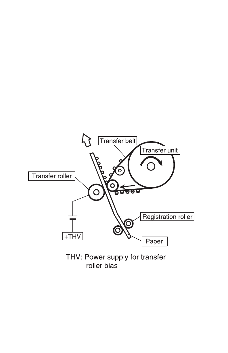
5021-0XX
Details of the transfer system
Second transfer (paper) process
In the second transfer process, the toner image on the transfer belt
is transferred to paper. See “Printer theory of operation” on
page 1-19 for second transfer roller location.
The transfer roller, normally separated from the transfer belt, is
positively biased by the power supply THV. The transfer roller
contacts the transfer belt as paper passes between the transfer
roller and the transf er belt. The positive bias of the transfer roller
causes the toner to release from the transfer belt and adhere to the
paper.
1-38 Service Manual
Page 65

5021-0XX
Transfer belt cleaning process
The residual toner on the surface of the transfer belt is removed
after the paper transfer process. See “Printer theory of operation”
on page 1-19 for transfer belt cleaner unit location.
The belt cleaner brush is a semiconductor-type fur brush. The
cleaning roller is charged by voltage FCBV. The resistance of the
cleaning brush against the cleaning roller charges the brush. The
brush in turn contacts the surface of the rotating tr ansfer belt. The
negatively charged toner adheres to the positively charged (FCBV)
brush, which cleans the transfer belt. The cleaning brush does not
contact the transfer belt during the imaging process.
Waste toner, adhering to the surface of the cleaning roller, is
removed by the cleaning blade, routed by the waste toner feeder to
the waste toner container wh ere it is deposited.
General information 1-39
Page 66

5021-0XX
Details of the optical system
In the optical system process, the printer utilizes a semiconductor
laser diode as a light source. This laser diode is controlled by fast
switching which matches the transmitted image data (video signal).
The generated laser light scans the OPC belt through a polygon
mirror and lens. The electrostatic latent images are formed on the
OPC belt.
The Optical printhead unit consists of following parts:
No. Description
1
2
3
4
5
6
7
PD: photo detector
Polygon mirror: hexahedral mirror that reflects the laser
beam
Cylinder lens: laser beam condenser
Laser unit: laser diode light emitting source
LDC: laser diode control circuit
BTD mirror: beam timing detector mirror to guide the
laser beam to PD
Scanner motor: rotates the polygon mirror
1-40 Service Manual
Page 67

No. Description
F-lens: laser beam focus lens
8
Mirror: laser beam path reflecting mirror
9
5021-0XX
General information 1-41
Page 68

5021-0XX
Details of the paper transportation system
In the paper transportation process, paper is automatically fed by
the pick-up roller and transported to the registration roller. The
registration roller synchronizes with the transfer belt. The
registration roller transports the paper to the transfer roller. During
the transfer process, the transfer roller forwards the paper to the
fuser rollers. During the fusing process, the fuser rollers transport
the fused paper to the exit roller and the exit roller pushes the final
paper out of the rear cover assembly.
The paper transportation system consists of the following parts:
No. Part Function
Paper tray Accommodates paper to be automatically fed
1
Pick-up roller Feeds paper one by one, preventing multi-feed.
2
Registration
3
roller
through the printer.
Transports and synchronizes paper with the
transfer belt.
1-42 Service Manual
Page 69

No. Part Function
Transfer roller Works in conjunction with the transfer belt to
4
Fuser unit Utilizes a heat roller to fuse the toner image to
5
transfer the image to paper and to transport the
paper to the fuser.
the paper.
5021-0XX
6
Paper exit
roller
Exits the fused paper from the printer.
General information 1-43
Page 70

5021-0XX
Fusing unit
The fusing unit utilizes a thermal fusing system that contains a
heated fusing roller and a belt-like backup roller. The heated roller
contains an inner heating element. The backup roller contains three
pressure members located behind the belt. Paper carrying a toner
image passes between the rollers where heat and pressure are
applied to the paper to fuse the toner to the paper.
The fusing unit consists of the following components:
No. Part Function
Fusing roller Used for fusing, containing a heater.
1
Back-up roller Pressure roller.
2
Fusing heater Heating device heated by a halogen lamp.
3
1-44 Service Manual
Page 71

No. Part Function
Thermistor Sensor that detects the temperature of the
4
Thermal fuse Protective device that prevents the fuser roller
5
fuser roller’s surf ace.
from being excessively heated.
5021-0XX
General information 1-45
Page 72

5021-0XX
Fusing process
1. When the paper reaches the fuser, the toner image is
transferred on the paper, but not yet fused to the paper.
2. The transported paper passes between the heated roller and
the back-up roller. The heated roller’s temperature is
approximately 338°F (170°C).
3. When the paper with toner image passes between the heated
roller and the backup rolle r, the heat from the heated roller in
combination with the pressure between the two rollers, melts
the toner, fusing it to the paper.
4. The fused paper then separates from the rollers and is
transported out of the printer into the output bin or is routed
back into the printer for printing on the other side of the duplex
print.
1-46 Service Manual
Page 73

Control system structure
Electrical system and function
The engine board controls most of the main electrical parts in this
printer.
No. Control process Function
5021-0XX
1 Print process
control
2 Laser output
control
3 Fuser
temperature
control
4 Toner sensing
control
5 Interface control
(video signal)
6 Operator panel
indicator
7 Error control Controls safe stop procedures when errors
Controls print process from paper feed
through paper exit.
Automatically controls laser output to the
default.
Controls fuser heater, allowing heated
roller to reach default temperature.
Controls sensing of toner empty status.
Processes the input and output signal with
external controller computer.
Displays printer operation status.
occur.
General information 1-47
Page 74

5021-0XX
Control of print process
Control block diagram
No. Control process Function
1 Sequence control Controls print sequence of printer.
2 Temperature
control
3Consumables’ life
control
4 Operator panel
control
5 Error processing
control
6 Interface control Controls receipt and transmission of interface
7 Laser control Controls laser scanning and laser power.
Controls temperature of fuser unit.
Controls toner empty status for each toner
cartridge and life of periodic replacement
parts.
Controls operator panel indication and
operator signals.
Senses errors occurring as well as stop
procedures.
signals from external controller.
Note: A micro CPU mounted on the engine board controls the print
processes.
1-48 Service Manual
Page 75

Print sequence diagram
5021-0XX
General information 1-49
Page 76
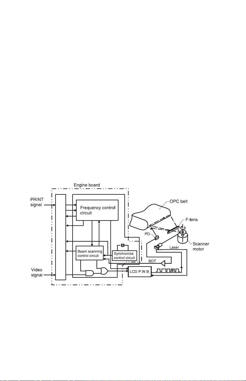
5021-0XX
Laser drive control circuit
The laser drive control circuit (LDC) consists of a video signal input
circuit, laser drive circuit, laser diode, output sensing circuit, and
output control circuit. See the illustration.
1. When the video signal is received, the laser drive control circuit
switches the laser diode s witch on and ra diates according to the
video signal.
2. The radiated laser beam senses the photo detector (PD). The
detected signal is returned to the output control circuit.
3. The output control circuit controls the radiated output to a
constant, by comparing the laser output default with the
feedback value transmitted from the output sensing circuit.
4. The laser beam, scanned by the scanner motor, is sensed by
the beam detector (PD), and then outputs the beam detecting
timing (BDT) signal.
1-50 Service Manual
Page 77

5021-0XX
Interface control
Interface type
Through the video interface, the RIP controls the printer and
operator panel using command/status communication and tr ansmits
the synchronized video data to the printer laser diode. The operator
panel is physically resident on the engine.
Interface connection
The interface connector of the laser printer is connect ed to the ho st
system as shown in the following illustration.
General information 1-51
Page 78

5021-0XX
1-52 Service Manual
Page 79

5021-0XX
2. Diagnostic information
Start
CAUTION: Remove power from the printer before you connect or
disconnect any cable, electr onic board or assembly, for personal
safety and to prevent damage to the printer. Always use the hand
grips on the side of the printer and be sur e your fingers are not
under the printer when you set the printer down.
Use the service error codes, user status messages, user error
messages, symptom tables, service checks, and diagnostic aids, to
determine the corrective action necessary to repair a malfunctioning
printer.
Service error codes are indicated by a three-digit error code. If a
service error code displays, go to the “Service er ror codes” on
page 2-2.
User status messages provide the user with information on the
current status of the printer. “Ready” displays on the first line of the
display unless Power Saver is invoked, then Power Saver is
displayed. If a user status message displays, go to the “Operator
messages” on page 2-9.
User error messages are indicated b y a tw o- or three-digit error code
which provides the user with inf ormation e xplaining a prob lem with a
print cartridge, paper jam, option, port, and so on. If a user error
message displays, go to the“Operator messages” on page 2-9.
The User Messages section sometimes allows a servicer to isolate
printer problems. This section also gives actions to be taken when
they do not set or clear.
If you have a failing symptom, go to the “Symptom tables” on
page 2-25. Locate your symptom and take the appropriate action.
If a service error code appears while you are working on the printer,
go to the “Service error codes” on page 2-2 and take the
appropriate action.
Diagnostic information 2-1
Page 80

5021-0XX
Service error codes
Error code Action
900
RIP Software
901
Yellow developer
clutch error (DCLY)
902
Magenta developer
clutch error (DCLM)
903
Cyan developer
clutch error (DCLC)
904
Black developer
clutch error (DCLK)
905
Yellow toner retract
solenoid error
(DSLY)
906
Magenta toner retract
solenoid error
(DSLM)
Contact customer service center, or Lexmark support
center
Go to “901—Yellow developer clutch service
check” on page 2-29.
Go to “902—Magenta developer clutch service
check” on page 2-31.
Go to “903—Cyan developer clutch service
check” on page 2-33.
Go to “904—Black developer clutch service
check” on page 2-35.
Go to “905—Y ellow toner retract solenoid service
check” on page 2-37.
Go to “906—Magenta toner retract solenoid
service check” on page 2-39.
907
Cyan toner retract
solenoid error
(DSLC)
908
Black toner retract
solenoid error
(DSLK)
2-2 Service Manual
Go to “907—Cyan toner retract solenoid service
check” on page 2-41.
Go to “908—Black toner retract solenoid service
check” on page 2-43.
Page 81

Error code Action
5021-0XX
910
Developing motor
(DM) error
911
Main motor (MM)
error
912
Power supply fan
(PSFAN) error
913
Fuser fan (FUFAN)
error
914
Laser fan error
915
Erase lamp error
916
Toner empty sensor
connection error 1
(TPD)
Go to “910—Developer motor service check” on
page 2-45.
Go to “911—Main motor service check” on
page 2-48.
Go to “912—Power supply fan service check” on
page 2-51.
Go to “913—Fuser fan service check” on
page 2-52.
Go to “914—Laser fan service check” on
page 2-53.
Go to “915—Erase lamp service check” on
page 2-54.
Go to “916—Toner empty sensor (sender-TPD)
service check” on page 2-56.
917
Toner empty sensor
connection error 2
(TTR)
918
High voltage power
supply connection
error
919
Secondary paper
feed assembly error
Go to “917—Toner empty sensor (receiver-TTR)
service check” on page 2-57.
Go to “918—HVPS connection service check” on
page 2-58.
Go to “919—Lower feed unit (secondary paper
assembly) service check” on page 2-59.
Diagnostic information 2-3
Page 82

5021-0XX
Error code Action
920
Fuser thermistor
error
921/922/923/924/925
Fuser temperature
error
92X
Fuser exhausted
930
Laser power error
931
Beam detector error
(BDT)
932
Scanner motor error
(SM)
Go to “920—Fuser thermistor service check” on
page 2-60.
Go to “921,922,923,924,925—Fuser assembly
service check” on page 2-61.
Fuser is in a maintenance state and needs to be
replaced before any other action can be taken.
Replace fuser assembly (see “Fuser assembly
removal” on page 4-9) and note whether any error
code exists.
Note: Fuser is a customer-order supply.
Indicates that printhead laser output is low.
Go to “930,931,932—Laser unit assembly service
check” on page 2-62.
Indicates that printhead laser scanning beam is not
detected by the beam sensor.
Go to “930,931,932—Laser unit assembly service
check” on page 2-62.
Indicates abnormal rotation of printhead scanner
motor.
Go to “930,931,932—Laser unit assembly service
check” on page 2-62.
939
RIP to engine
communication
945
Engine board
NVRAM error
2-4 Service Manual
Indicates that the RIP board processor cannot
communicate with processor. Remove and reinstall
RIP board. Go to “RIP board removal” on
page 4-45. Ensure RIP board makes proper
connection with engine controller board connector.
Ensure engine controller board is properly installed.
If error persists, replace RIP board. If error still
persists, replace engine controller board. See
“Engine controller board removal” on page 4-55.
Turn power off and then back on.
If error still exists, replace engine controller board.
Go to “Engine controller board removal” on
page 4-55.
Page 83

Error code Action
5021-0XX
946
Engine controller
hardware error
947
Process timing clock
error
953
NVRAM chip failure
954
NVRAM CRC failure
955
Code CRC
955
Code ECC
956
Processor failure
Turn power off and then back on.
If error still exists, replace engine controller board.
Go to “Engine controller board removal” on
page 4-55.
Indicates synchronization signal from main motor
(MM) is not inputted.
Go to “911—Main motor service check” on
page 2-48.
Indicates engine board NVRAM failed.
Replace engine controller board. Go to “Engine
controller board removal” on page 4-55.
Indicates the operator panel failed CRC check.
Replace the operator panel cable. Go to “Operator
panel cable removal” on page 4-54.
Indicates that on-board NAND flash located on RIP
board has failed CRC check. Replace RIP board. Go
to “RIP board removal” on page 4-45.
Indicates that on-board NAND flash located on RIP
board has failed CRC check. Replace RIP board. Go
to “RIP board removal” on page 4-45.
Indicates a problem with RIP board processor.
Replace RIP board. Go to “RIP board removal” on
page 4-45.
957
ASIC failure
958
NAND failure
959
SRAM failure
960
Memory error
Indicates a problem with RIP board ASIC. Replace
RIP board. Go to “RIP board removal” on
page 4-45.
Indicates that on-board NAND flash located on RIP
board has failed. Replace RIP board. Go to “RIP
board remova l ” on page 4-45.
Indicates a problem with RIP board SRAM. Replace
RIP board. See “RIP board removal” on page 4-45.
Indicates that RIP board soldered RAM is bad.
Replace RIP board. Go to “RIP board removal” on
page 4-45.
Diagnostic information 2-5
Page 84

5021-0XX
Error code Action
961
Memory error
962
Memory error
964
Emulation error
975
Unrecognizable
network port
976
Unrecognizable
software error in
network port
Indicates RAM in slot 1 is bad. Replace memory in
slot 1. If error persists, replace RIP board. Go to “RIP
board removal” on page 4-45.
Indicates RAM in slot 2 is bad. Replace memory in
slot 2. If error persists, replace RIP board. Go to “RIP
board removal” on page 4-45.
Indicates a failure within a download emulation that is
programmed into the firmware card. To troubleshoot,
perform the following:
1. Disable download emulation. Go to “Disabling
download emulations” on page 3-1.
2. Reprogram download emulation into the firmware
card.
3. If 964 error is still present, replace firmware card
and download emulation again.
Indicates a problem with the network port.
• Network printer
Replace RIP board. Go to “RIP board removal” on
page 4-45.
• Standard printer with INA
Replace INA. If error persists, replace RIP board. Go
to “RIP board removal” on page 4-45.
Indicates a problem with network port.
Network printer
Replace RIP board. Go to “RIP board removal” on
page 4-45.
• Standard printer with INA
Replace INA. If error persists, replace RIP board. Go
to “RIP board removal” on page 4-45.
978
Bad checksum while
programming
network port
2-6 Service Manual
Indicates a problem with the network port.
• Network printer
Replace RIP board. Go to “RIP board removal” on
page 4-45.
• Standard printer with INA
Replace INA. If error persists, replace RIP board. Go
to “RIP board removal” on page 4-45.
Page 85

Error code Action
5021-0XX
979
Flash parts failed
while programming
network port
980
Duplex controller
hardware error 1
982
Duplex controller
hardware error 1
983
Duplex motor error
Indicates a problem with the network port.
• Network printer
Replace RIP board. Go to “RIP board removal” on
page 4-45.
• Standard printer with INA
Replace INA. If terror persists, replace RIP board. Go
to “RIP board removal” on page 4-45.
Indicates a communication problem between engine
controller board and duplex unit.
• Ensure that duplex cable is connected.
• If cable is connected and error persists, replace
duplex unit.
• If replacing duplex unit does not clear error,
replace engine controller board. Go to “Engine
controller board removal” on page 4-55.
Indicates a blown motor-protective current fuse
located on DCTL board in duplex unit. Replace
duplex unit.
984
Outer pass select
solenoid error
985
Duplex connection
error 1
986
Duplex connection
error 2
Indicates a duplex solenoid problem. Replace duplex
unit.
Indicates that there is a connection problem between
the duplex unit and the low voltage power supply.
Go to “985—Duplex connection error 1 service
check” on page 2-63.
Indicates that there is a connection problem between
the duplex unit and engine controller board.
Go to “986—Duplex connection error 2 service
check” on page 2-64.
Diagnostic information 2-7
Page 86

5021-0XX
Error code Action
990
Transfer belt (transfer
unit) error
991
Transfer roller clutch
error
992
Cleaning roller clutch
error
993
Fuser clutch error
994
OPC belt marker
sensor error
995
Charger HV unit error
Indicates unstable transfer belt rotation; color
matching cannot be secured.
Go to “990—Transfer belt unit service check” on
page 2-65.
Indicates a problem with transfer roller cable
connection.
Go to “991—Transfer roller clutch service check”
on page 2-67.
Indicates a problem with transfer unit cleaning roller
clutch cable connection.
Go to “992—Transfer belt cleaning roller clutch
service check” on page 2-68.
Indicates a problem with fuser clutch cable
connection.
Go to “993—Fuser clutch service check” on
page 2-69.
Indicates marker on OPC belt (photodeveloper
cartridge) is not being properly detected by marker
sensor.
Go to “994—OPC belt marker sensor service
check” on page 2-70.
Indicates a problem with HVPS charging voltage
supplied to the OPC (photodeveloper cartridge)
charging unit.
Go to “995—High voltage power supply (HVPS)
service check” on page 2-72.
996
LVPS error
2-8 Service Manual
Go to “996—Low voltage power supply (LVPS)
service check” on page 2-74.
Page 87

Operator messages
Message Description Action
5021-0XX
Change Tray <x>
<type> <size>
Close Duplex Door Duplex door is
Close Front Cover Front cover is open. Open and reclose front cover.
Printer is requesting
different media than
what is loaded in
specified tray or
defined by paper
size or paper type
settings for tray.
open.
Ensure tray contains proper
type and size of media for job.
Remove tray from machine.
Remove paper from tray.
Change paper size length.
Observe paper size sensor
actuator, located on the side of
the tray, movement as you
change to various paper sizes.
Actuator should move back
and forth. If actuator does not
move back and forth, replace
paper tray.
If problem persists, go to
“Paper size sensing service
check” on page 2-87.
Ensure that strap connecting
front cover to printer is
attached to printer.
If problem persists, go to
“Cover open service check”
on page 2-75.
Close Rear Cover Rear cover
assembly is open.
Close Top Cover Top cover is open. Open and reclose top cover.
Open and close rear cover
assembly.
If problem persists, go to
“Cover open service check”
on page 2-75.
If problem persists, go to
“Cover open service check”
on page 2-75.
Diagnostic information 2-9
Page 88

5021-0XX
Message Description Action
Did you replace
Fuser?
Did you replace the
Photodev Cart?
Fuser page counter
has exceeded fuser
page limit.
This message
appears when the
top door is closed or
when you answer
another
replacement
message, and
photodeveloper
cartridge is either in
a warning or
exhausted state
requiring that you
replace it.
Secondary
message appears
with instructions.
Replace fuser.
Note: This is a customer
ordered part.
Pressing Select clears
maintenance counter.
Press Stop to continue
printing. This does not clear
maintenance counter. Fuser
remains in warning state, and
message appears again each
time rear cover is opened.
Replace photodeveloper
cartridge and press Go.
Pressing Go clears
maintenance counter.
Press Stop to continue
printing. This does not clear
maintenance counter.
Message 83 Photodev
Exhausted returns after
pressing Stop. Photode veloper
cartridge remains in warning
state, and this message
appears again each time top
cover is opened.
2-10 Service Manual
Page 89

Message Description Action
5021-0XX
Menus Disabled Printer menus have
been disabled. This
occurs when
<Menu> is pressed
while printer is
Ready and menu
lockout is active.
The printer display
shows this
message for one
second and then
returns to Ready
message.
No button actions
are possible while
this message is
displayed.
Not Ready Printer is in not
ready state, which
means it is not
ready to receive or
process data.
This message
displays when Stop
is pressed during a
print job.
If operator has disabled menu
and you want to run operator
print tests, turn machine Off
and then press Return and
Select as you turn machine
on.
Press Go to take the printer
out of the not ready state.
Perf orming Self Test Printer is running
normal series of
start-up tests after it
is powered on.
When tests are
complete, printer
returns to Ready.
No button actions
are possible while
this message is
displayed.
Printer performs self-test.
Diagnostic information 2-11
Page 90

5021-0XX
Message Description Action
Power Saver Printer is ready to
receive and process
data. If printer
remains inactive for
period of time
specified in Power
Saver menu item
(20 minutes is
factory default),
Power Saver
message replaces
Ready message on
display.
Remove paper
Standard bin
Supplies At least one printer
TMA Toner mass
Output bin is full.
Bin full warning is
cleared when
output level
reported by bin is
no longer full.
supply requires
attention.
adjustment.
Printer is
performing a toner
mass adjustment.
This is a secondary
message that
appears on second
line of operator
panel when Engine
Warming and
Performing Self
Test messages
appear.
Send a job to print.
Press Go to quickly warm
printer to normal operating
temperature and display
Ready message.
Go to “Output tray full
service check” on page 2-85.
Press Menu to open Supplies
Menu and identify which
supply item needs replacing.
Replace appropriate printer
supply.
Wait for message to clear.
2-12 Service Manual
Page 91

5021-0XX
Message Description Action
Tray <x> Empty I nput tray is empty. Load media of size and type
requested in second line of
display in specified tray. Printer
automatically clears message
and continues printing job. If
problem persists, go to “Tray
empty service check” on
page 2-95.
Tray <x> missing Specified tray is
30 <color> Toner
Cart Missing
32 Unsupported
Print Cartridge
34 Incorrect Media Printer has detected
34 Short Paper Printer has
either missing or
not fully inserted.
Specified cartridge
(Cyan, Magenta,
Yellow, or Black) is
not installed in the
printer.
Unsupported print
cartridge has been
installed in printer.
a mismatch in
requested media
type and type
loaded.
determined that
length of paper in
source specified on
second line of
display is too short
to print formatted
data.
Ensure tray is fully inserted in
printer. If problem persists, go
to “Paper size sensing
service check” on page 2-87.
Insert cartridge and close front
cover to clear message. If
message persists, go to
“Missing toner cartridge
service check” on page 2-81.
Remove print cartridge and
insert a supported print
cartridge. If problem persists,
go to “Missing toner
cartridge service check” on
page 2-81.
Remove paper tray. Ensure
media selected for print job is
in tray. If problem persists, go
to “Incorrect media service
check” on page 2-78.
Press Go to clear message.
Ensure paper size setting in
paper menu is correct for
paper size. If problem persists,
go to “Paper size sensing
service check” on page 2-87.
Diagnostic information 2-13
Page 92

5021-0XX
Message Description Action
35 Res Save Off
Deficient Memory
37 Insufficient
Collation Area
37 Insufficient
Defrag Memory
Printer lacks
memory needed to
enable Resource
Save. This
message usually
indicates too much
memory is allocated
for one or more of
printer link buffers.
Printer memory (or
hard disk, if
installed) does not
have free space
necessary to collate
print job.
Printer cannot
defragment flash
memory, because
printer memory
used to store
undeleted flash
resources is full.
Press Go to disable Resource
Save and continue printing.
To enable Resource Save after
you get this message:
• Make sure link buffers are
set to Auto, and exit menus
to activate link buffer
changes.
• When Ready is displayed,
enable Resource Save from
the Setup Menu.
Install additional memory.
Press Go to print portion of job
already stored and begin
collating rest of job.
Press Menu to open Job Menu
and cancel current job.
Delete fonts, macros, and
other data in printer memory.
Install additional printer
memory.
2-14 Service Manual
Page 93

Message Description Action
5021-0XX
37 Insufficient
Memory
38 Memory Full Printer is
Printer memory is
full and cannot
continue processing
current print jobs.
processing data,
but memory used to
store pages is full.
Press Go to clear message
and continue current print job.
Printer frees memory by
deleting oldest held job and
continues deleting held jobs
until there is enough printer
memory to process job.
Press Stop to clear message
without deleting any held jobs.
Current job may not print
correctly.
Press Menu to open Job Menu
and cancel current job.
To avoid this error in future:
• Delete fonts, macros, and
other data in printer
memory.
• Install additional printer
memory.
Note: Messages 37
Insufficient Memory and Held
Jobs May Be Lost alternate on
display.
Press Go to clear message
and continue printing job. Job
may not print correctly.
Press Menu to open Job Menu
and cancel current job.
To avoid this error in future:
• Simplify print job by
reducing amount of tex t or
graphics on a page and
deleting unnecessary
downloaded fonts or
macros.
• Install additional printer
memory.
Diagnostic information 2-15
Page 94

5021-0XX
Message Description Action
39 Complex Page Page may not print
correctly because
print information on
page is too
complex.
51 Defective Flash Printer detects
defective flash
memory.
52 Flash Full There is not enough
free space in flash
memory to store
data you are trying
to download.
Press Go to clear message
and continue printing job. Job
may not print correctly.
Press Menu to open Job Menu
and cancel current job.
To avoid this error in future:
• Reduce complexity of page
by reducing amount of text
or graphics on page and
deleting unnecessary
downloaded fonts or
macros.
• Set Page Protect to On in
Setup Menu.
• Install additional printer
memory.
Press Go to clear message
and continue printing. You
must install different flash
memory before you can
download any resources to
flash.
Press Go to clear message
and continue printing.
Downloaded fonts and macros
not previously stored in flash
memory are deleted.
Delete fonts, macros, and
other data stored on flash
memory.
Install flash memory with more
storage capacity.
53 Unformatted
Flash
2-16 Service Manual
Printer detects
unformatted flash
memory.
Press Go to clear message
and continue printing. You
must format flash memory
before you can store any
resources on it.
If error message remains, flash
memory may be defective and
require replacing.
Page 95

Message Description Action
5021-0XX
54 Serial Option
<x> Error
54 Standard Serial
Error
54 Network <x>
Software Error
54 Std Network
Software Error
54 Std Par ENA
Connection Lost
54 Par <x> ENA
Connection Lost
Printer has detected
a serial interface
error on a serial
port.
Printer cannot
establish
communications
with an installed
network port.
Printer has lost
connection to an
external print server
(also called an
external network
adapter or ENA).
Make sure serial link is set up
correctly and you are using
appropriate cable.
Press Go to clear message
and continue printing. Job may
not print correctly.
Press Menu to open Job Menu
and reset printer.
Press Go to clear message
and continue printing. Job may
not print correctly.
Program new firmware for
network interface by way of
parallel port.
Press Menu to open Job Menu
and reset printer.
Make sure cable connecting
ENA and printer is securely
attached. Turn printer off and
then on to reset printer.
Press Go to clear the
message. Printer erases any
reference to ENA and then
resets.
55 Unsupported
Option in Slot <x>
55 Unsupported
Flash in Slot <x>
56 Serial Port <x>
Disabled
An unsupported
option card is
installed in one of
ports or an
unsupported flash
DIMM is installed in
a memory slot.
Data has been sent
to printer through a
serial port, but
serial port is
disabled.
Turn off and unplug printer.
Remove unsupported option.
Plug in printer and turn it on.
Press Go to clear message.
Printer discards any data
received through serial port.
Make sure Serial Buffer menu
item in Serial Menu is not set
to Disabled.
Diagnostic information 2-17
Page 96

5021-0XX
Message Description Action
56 Parallel P ort <x>
Disabled
56 Std Parallel Port
Disabled
57 Configuration
Change
58 Too Many Flash
Options
61 Defective Disk Printer detects a
62 Disk Full There is not enough
Data has been sent
to printer through a
parallel port, but
parallel port is
disabled.
Printer cannot
restore confidential
or held jobs on hard
disk because print
configuration has
changed.
Too many flash
memory options are
installed on printer.
defective hard disk.
memory on hard
disk to store data
sent to printer.
Press Go to clear message.
Printer discards any data
received through parallel port.
Make sure Parallel Buffer
menu item in Parallel Menu is
not set to Disabled.
Press Go to clear message.
Note: Messages 57
Configuration Change and
Held Jobs May Not Be
Restored alternate on display.
Turn off and unplug printer.
Remove excess flash memory.
Plug in printer and turn it on.
Press Go to clear message
and continue printing.
Install a different hard disk
before you perform any
operations that require one.
Press Go to clear message
and continue processing. Any
information not previously
stored on hard disk is deleted.
Delete fonts, macros, and
other data stored on hard disk.
63 Unformatted
Disk
2-18 Service Manual
Printer detects an
unformatted hard
disk.
Press Go to clear message
and continue printing.
Format disk before performing
any disk operations. To format
disk, select Format Disk from
Utilities Menu.
If error message remains, hard
disk may be defective and
require replacing. Install a new
hard disk and format it.
Page 97

Message Description Action
5021-0XX
64 Unsupported
Disk Format
80 Transfer Roller
Missing
82 Waste Bottle
Nearly Full
82 Waste Toner
Bottle Full or
Missing
83 Photodev Cart
Exhausted
83 Photodev Cart
Life Warning
Printer detects an
unsupported disk
format.
Transfer roller is
missing or not
properly installed.
Toner waste bottle
is almost full.
Waste toner bottle
is full or missing.
Photodeveloper
cartridge is
completely used.
Photodeveloper
cartridge is nearing
end of life.
Press Go to clear message.
Format disk.
Note: Disk operations are not
allowed until disk is formatted.
Ensure transfer roller is
properly installed. If problem
persists, go to “T ransfer roller
missing service check” on
page 2-93.
Press Go to clear message
and continue printing.
Replace waste toner bottle. If
message does not clear, go to
“Waste toner bottle service
check” on page 2-97.
Replace waste toner bottle and
press Go to clear message.
“Waste toner bottle service
check” on page 2-97.
Replace photodeveloper
cartridge.
Press Go to clear message
and continue printing.
Replace photodeveloper
cartridge.
83 Photodev Cart
Missing
Photodeveloper
cartridge is either
missing or
incorrectly installed.
Correctly install
photodeveloper cartridge to
clear message and continue
printing.
Diagnostic information 2-19
Page 98

5021-0XX
Message Description Action
87 Fuser Exhausted Fuser is completely
used.
87 Fuser Life
Warning
Fuser is nearing
end of life.
Replace fuser.
If problem persists, check
cable for co nt inuity that
connects engine controller
board connector FUCN and
fuser. If cable is bad, replace
cable. Otherwise, replace
engine controller board. Go to
“Engine controller board
removal” on page 4-55.
Press Go to clear message
and continue printing.
Replace fuser. Go to “Fuser
assembly removal” on
page 4-9.
Note: Fuser is a customer
ordered part.
If problem persists, check
cable for co nt inuity that
connects engine controller
board connector FUCN and
fuser. If cable is bad, replace
cable. Otherwise, replace
engine controller board. Go to
“Engine controller board
removal” on page 4-55.
87 Fuser Missing Fuser is either
missing or
incorrectly installed.
2-20 Service Manual
Correctly install fuser. Go to
“Fuser assembly removal”
on page 4-9.
If problem persists, check
cable for co nt inuity that
connects engine controller
board connector FUCN and
fuser. If cable is bad, replace
cable. Otherwise, replace
engine controller board. Go to
“Engine controller board
removal” on page 4-55.
Page 99

Message Description Action
5021-0XX
88 <color> Toner
Empty
88 <color> Toner
Low
Printer has ceased
operating because
specified toner
cartridge is empty.
Printer has detected
that toner supply in
specified cartridge
is low.
Replace specified toner
cartridge. If problem persists,
go to “Toner low/empty
service check” on page 2-92.
Replace specified toner
cartridge. If problem persists,
go to “Toner low/empty
service check” on page 2-92.
Diagnostic information 2-21
Page 100
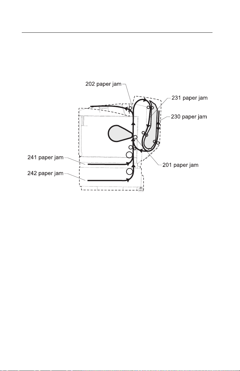
5021-0XX
Paper jam me ssages
The following illustration lists paper jam messages indicating where
paper jam occurred.
CAUTION: When clearing paper jams, inside of the printer may be
hot. Allow printer to cool bef ore touching any internal components.
2-22 Service Manual
 Loading...