

Page 1

First Edition (March, 1996)
The following paragraph does not apply to the United Kingdom or any country where such
provisions are inconsistent with local law: LEXMARK INTERNATIONAL, INC. PROVIDES
THIS PUBLICATION “AS IS” WITHOUT WARRANTY OF ANY KIND, EITHER EXPRESS
OR IMPLIED, INCLUDING, BUT NOT LIMITED TO, THE IMPLIED WARRANTIES OF
MERCHANTABILITY OR FITNESS FOR A PARTICULAR PURPOSE. Some states do
not allow disclaimer of express or implied warranties in certain transactions, therefore, this
statement may not apply to you.
This publication could include technical inaccuracies or typographical errors. Changes are
periodically made to the information herein; these changes will be incorporated in later
editions of the publication. Improvements or changes in the products or the programs
described in this publication may be made at any time. Publications are not stocked at the
address given below; requests for publications should be made to your point of purchase.
A form for reader’s comments is provided at the back of this publication. If the form has
been removed, comments may be addressed to Lexmark International, Inc., Department
F95/035-3, 740 New Circle Road, Lexington, Kentucky 40511, U.S.A. Lexmark may use
or distribute any of the information you supply in any way it believes appropriate without
incurring any obligation to you.
Lexmark, MarkNet, MarkVision, Optra and WinWriter are trademarks of Lexmark
International, Inc.
IBM and ExecJet are registered trademarks of the International Business Machines
Corporation in the United States and/or in other countries. ExecJet is under license from
International Business Machines Corporation.
Other trademarks are the property of their respective owners.
© Copyright Lexmark International, Inc. 1996. All Rights Reserved.
UNITED STATES GOVERNMENT RESTRICTED RIGHTS
This software and documentation are provided with RESTRICTED RIGHTS. Use,
duplication or disclosure by the Government is subject to restrictions as set forth in
subparagraph (c)(1)(ii) of the Rights in Technical Data and Computer Software clause at
DFARS 252.227-7013 and in applicable FAR provisions: Lexmark International, Inc.,
Greenwich, CT 06836.
Page 2

Contents
4026-0XX . . . . . . . . . . . . . . . . . . . . . . . . . . . . . . . . . . . . . . . . . . . . . 1-1
Diagnostics . . . . . . . . . . . . . . . . . . . . . . . . . . . . . . . . . . . . . . . . . 1-3
Start . . . . . . . . . . . . . . . . . . . . . . . . . . . . . . . . . . . . . . . . . . . 1-3
Power-On Self Test (Post). . . . . . . . . . . . . . . . . . . . . . . . . . 1-4
Service Error Codes. . . . . . . . . . . . . . . . . . . . . . . . . . . . . . . 1-5
Diagnostics Aids . . . . . . . . . . . . . . . . . . . . . . . . . . . . . . . . . . . . 1-15
Printer Diagnostic Test. . . . . . . . . . . . . . . . . . . . . . . . . . . . 1-15
Service Diagnostic Test Page . . . . . . . . . . . . . . . . . . . . . . 1-16
User Mode Print Test Page . . . . . . . . . . . . . . . . . . . . . . . . 1-18
Configuration Mode . . . . . . . . . . . . . . . . . . . . . . . . . . . . . . 1-19
Hex Trace. . . . . . . . . . . . . . . . . . . . . . . . . . . . . . . . . . . . . . 1-21
Restoring Factory Defaults. . . . . . . . . . . . . . . . . . . . . . . . . 1-22
Connectors. . . . . . . . . . . . . . . . . . . . . . . . . . . . . . . . . . . . . . . . 1-23
Parts Catalog . . . . . . . . . . . . . . . . . . . . . . . . . . . . . . . . . . . . . . 1-30
4027-04W . . . . . . . . . . . . . . . . . . . . . . . . . . . . . . . . . . . . . . . . . . . . . 2-1
Diagnostics . . . . . . . . . . . . . . . . . . . . . . . . . . . . . . . . . . . . . . . . . 2-3
Start . . . . . . . . . . . . . . . . . . . . . . . . . . . . . . . . . . . . . . . . . . . 2-3
Power-On Self Test (POST). . . . . . . . . . . . . . . . . . . . . . . . . 2-6
Diagnostic Aids. . . . . . . . . . . . . . . . . . . . . . . . . . . . . . . . . . . . . 2-10
Customer Test Page (From WPS) . . . . . . . . . . . . . . . . . . . 2-10
Customer Test Page (Stand Alone) . . . . . . . . . . . . . . . . . . 2-10
Developed Image Test . . . . . . . . . . . . . . . . . . . . . . . . . . . . 2-10
WPS.INI File . . . . . . . . . . . . . . . . . . . . . . . . . . . . . . . . . . . . 2-11
Connectors. . . . . . . . . . . . . . . . . . . . . . . . . . . . . . . . . . . . . . . . 2-12
Parts Catalog . . . . . . . . . . . . . . . . . . . . . . . . . . . . . . . . . . . . . . 2-18
4033 . . . . . . . . . . . . . . . . . . . . . . . . . . . . . . . . . . . . . . . . . . . . . . . . . 3-1
Diagnostics . . . . . . . . . . . . . . . . . . . . . . . . . . . . . . . . . . . . . . . . . 3-3
Start . . . . . . . . . . . . . . . . . . . . . . . . . . . . . . . . . . . . . . . . . . . 3-3
Power Test. . . . . . . . . . . . . . . . . . . . . . . . . . . . . . . . . . . . . . 3-3
Reset, LAN Connected. . . . . . . . . . . . . . . . . . . . . . . . . . . . . 3-3
Symptoms after Reset . . . . . . . . . . . . . . . . . . . . . . . . . . . . . 3-4
Diagnostic Aids. . . . . . . . . . . . . . . . . . . . . . . . . . . . . . . . . . . . . . 3-5
Sample Print Test (Models 20X and 30X) . . . . . . . . . . . . . . 3-5
Wrap Test for Adapter Ports. . . . . . . . . . . . . . . . . . . . . . . . . 3-5
LAN Connection Check . . . . . . . . . . . . . . . . . . . . . . . . . . . . 3-6
Printer and LAN checks . . . . . . . . . . . . . . . . . . . . . . . . . . . . 3-6
Printer checks. . . . . . . . . . . . . . . . . . . . . . . . . . . . . . . . . . . . 3-7
LAN checks . . . . . . . . . . . . . . . . . . . . . . . . . . . . . . . . . . . . . 3-7
Parts Catalog . . . . . . . . . . . . . . . . . . . . . . . . . . . . . . . . . . . . . . . 3-8
Contents
iii
Page 3

4037 / 4047-05E . . . . . . . . . . . . . . . . . . . . . . . . . . . . . . . . . . . . . . . .4-1
Diagnostics . . . . . . . . . . . . . . . . . . . . . . . . . . . . . . . . . . . . . . . . 4-3
Start . . . . . . . . . . . . . . . . . . . . . . . . . . . . . . . . . . . . . . . . . . . 4-3
Power-on Self Test (POST). . . . . . . . . . . . . . . . . . . . . . . . . 4-5
Diagnostic Aids . . . . . . . . . . . . . . . . . . . . . . . . . . . . . . . . . . . . . 4-9
Print Test (Main Menu) . . . . . . . . . . . . . . . . . . . . . . . . . . . . 4-9
Diagnostics Mode . . . . . . . . . . . . . . . . . . . . . . . . . . . . . . . . 4-9
Developed Image Test . . . . . . . . . . . . . . . . . . . . . . . . . . . . 4-9
Diagnostics Print Test 1. . . . . . . . . . . . . . . . . . . . . . . . . . . 4-10
Diagnostics Print Test 2. . . . . . . . . . . . . . . . . . . . . . . . . . . 4-10
Page Count Display Or Initialize . . . . . . . . . . . . . . . . . . . . 4-10
Wrap Test . . . . . . . . . . . . . . . . . . . . . . . . . . . . . . . . . . . . . 4-11
Button Test . . . . . . . . . . . . . . . . . . . . . . . . . . . . . . . . . . . . 4-11
Button Lockout Mode (4047 Only). . . . . . . . . . . . . . . . . . . 4-12
LCD Test. . . . . . . . . . . . . . . . . . . . . . . . . . . . . . . . . . . . . . 4-12
Sensor Test. . . . . . . . . . . . . . . . . . . . . . . . . . . . . . . . . . . . 4-12
Error Log . . . . . . . . . . . . . . . . . . . . . . . . . . . . . . . . . . . . . . 4-13
Storage . . . . . . . . . . . . . . . . . . . . . . . . . . . . . . . . . . . . . . . 4-13
Adjustments . . . . . . . . . . . . . . . . . . . . . . . . . . . . . . . . . . . . . . . 4-14
Print Head Calibration . . . . . . . . . . . . . . . . . . . . . . . . . . . . 4-14
Print Registration Adjustment . . . . . . . . . . . . . . . . . . . . . . 4-14
Advanced Setup Menu (Early 4037 Models Only). . . . . . . 4-15
Storage . . . . . . . . . . . . . . . . . . . . . . . . . . . . . . . . . . . . . . . 4-15
Fastbytes. . . . . . . . . . . . . . . . . . . . . . . . . . . . . . . . . . . . . . 4-16
Hex Trace . . . . . . . . . . . . . . . . . . . . . . . . . . . . . . . . . . . . . 4-16
Fuser Temperature . . . . . . . . . . . . . . . . . . . . . . . . . . . . . . 4-16
Connectors . . . . . . . . . . . . . . . . . . . . . . . . . . . . . . . . . . . . . . . . 4-17
Parts Catalog. . . . . . . . . . . . . . . . . . . . . . . . . . . . . . . . . . . . . . 4-18
4039-1XX . . . . . . . . . . . . . . . . . . . . . . . . . . . . . . . . . . . . . . . . . . . . . .5-1
Diagnostics . . . . . . . . . . . . . . . . . . . . . . . . . . . . . . . . . . . . . . . . 5-3
Failures With Error Codes. . . . . . . . . . . . . . . . . . . . . . . . . . 5-3
Power-On Self Test (POST) . . . . . . . . . . . . . . . . . . . . . . . . 5-8
Diagnostic Aids . . . . . . . . . . . . . . . . . . . . . . . . . . . . . . . . . . . . . 5-9
Diagnostics Mode . . . . . . . . . . . . . . . . . . . . . . . . . . . . . . . . 5-9
Alphabetical List of Diagnostic Aids. . . . . . . . . . . . . . . . . . . 5-9
Operator Panel Tests . . . . . . . . . . . . . . . . . . . . . . . . . . . . 5-15
Print Tests . . . . . . . . . . . . . . . . . . . . . . . . . . . . . . . . . . . . . 5-18
Network Connections and Checks . . . . . . . . . . . . . . . . . . 5-20
LAN Information. . . . . . . . . . . . . . . . . . . . . . . . . . . . . . . . . 5-21
Laser Printer Reference Handbook
iv
Page 4

Adjustments . . . . . . . . . . . . . . . . . . . . . . . . . . . . . . . . . . . . . . . 5-22
Envelope Restraint Spring . . . . . . . . . . . . . . . . . . . . . . . . . 5-22
Paper Restraint Spring. . . . . . . . . . . . . . . . . . . . . . . . . . . . 5-22
Printhead Skew - Level 1 . . . . . . . . . . . . . . . . . . . . . . . . . . 5-23
Printhead Skew - Level 2 . . . . . . . . . . . . . . . . . . . . . . . . . . 5-24
Connectors. . . . . . . . . . . . . . . . . . . . . . . . . . . . . . . . . . . . . . . . 5-25
Parts Catalog . . . . . . . . . . . . . . . . . . . . . . . . . . . . . . . . . . . . . . 5-28
4040 . . . . . . . . . . . . . . . . . . . . . . . . . . . . . . . . . . . . . . . . . . . . . . . . . 6-1
Maintenance Approach. . . . . . . . . . . . . . . . . . . . . . . . . . . . . . . . 6-3
Diagnostic Information . . . . . . . . . . . . . . . . . . . . . . . . . . . . . . . . 6-4
Diagnostic Approach . . . . . . . . . . . . . . . . . . . . . . . . . . . . . . 6-4
Start . . . . . . . . . . . . . . . . . . . . . . . . . . . . . . . . . . . . . . . . . . . 6-4
Troubleshooting . . . . . . . . . . . . . . . . . . . . . . . . . . . . . . . . . . 6-5
Error Code/Message Tables . . . . . . . . . . . . . . . . . . . . . . . . 6-6
Operator Codes . . . . . . . . . . . . . . . . . . . . . . . . . . . . . . . . . . 6-8
Diagnostic Information . . . . . . . . . . . . . . . . . . . . . . . . . . . . 6-10
Symptom Tables . . . . . . . . . . . . . . . . . . . . . . . . . . . . . . . . 6-11
Diagnostic Aids. . . . . . . . . . . . . . . . . . . . . . . . . . . . . . . . . . . . . 6-16
Interlock Override. . . . . . . . . . . . . . . . . . . . . . . . . . . . . . . . 6-16
Diagnostics Mode Tests. . . . . . . . . . . . . . . . . . . . . . . . . . . 6-20
Adjustments . . . . . . . . . . . . . . . . . . . . . . . . . . . . . . . . . . . . . . . 6-26
Envelope Feeder Separation Guide and Lower Separation Roll-
er Gap Adjustment. . . . . . . . . . . . . . . . . . . . . . . . . . . . . . . 6-26
Paper Drawer Cassette Side Registration Adjustment. . . . 6-27
Connectors. . . . . . . . . . . . . . . . . . . . . . . . . . . . . . . . . . . . . . . . 6-28
System Board Connector Signals . . . . . . . . . . . . . . . . . . . 6-28
Paper Deck Switches, Sensors, Clutches, Solenoid, Motors. . .
6-37
Paper Deck Printed Circuit Boards. . . . . . . . . . . . . . . . . . . 6-37
Paper Deck Connectors. . . . . . . . . . . . . . . . . . . . . . . . . . . 6-37
Option Controller Interface Connectors . . . . . . . . . . . . . . . 6-41
Parts Catalog . . . . . . . . . . . . . . . . . . . . . . . . . . . . . . . . . . . . . . 6-43
Contents
v
Page 5

4047-05W . . . . . . . . . . . . . . . . . . . . . . . . . . . . . . . . . . . . . . . . . . . . .7-1
Diagnostics . . . . . . . . . . . . . . . . . . . . . . . . . . . . . . . . . . . . . . . . 7-3
Start . . . . . . . . . . . . . . . . . . . . . . . . . . . . . . . . . . . . . . . . . . . 7-3
Power-On Self Test (POST) . . . . . . . . . . . . . . . . . . . . . . . . 7-6
Diagnostic Aids . . . . . . . . . . . . . . . . . . . . . . . . . . . . . . . . . . . . 7-10
Customer Test Page (From WPS). . . . . . . . . . . . . . . . . . . 7-10
Customer Test Page (Stand Alone). . . . . . . . . . . . . . . . . . 7-10
Developed Image Test . . . . . . . . . . . . . . . . . . . . . . . . . . . 7-11
Service Diskette. . . . . . . . . . . . . . . . . . . . . . . . . . . . . . . . . 7-11
Diagnostics Test Page. . . . . . . . . . . . . . . . . . . . . . . . . . . . 7-12
Diagnostics Test Page 2 . . . . . . . . . . . . . . . . . . . . . . . . . . 7-12
Envelope Print Test. . . . . . . . . . . . . . . . . . . . . . . . . . . . . . 7-12
Hex Trace . . . . . . . . . . . . . . . . . . . . . . . . . . . . . . . . . . . . . 7-13
Set Page Count. . . . . . . . . . . . . . . . . . . . . . . . . . . . . . . . . 7-13
Wrap Test . . . . . . . . . . . . . . . . . . . . . . . . . . . . . . . . . . . . . 7-14
Error Log . . . . . . . . . . . . . . . . . . . . . . . . . . . . . . . . . . . . . . 7-14
Printhead Calibration. . . . . . . . . . . . . . . . . . . . . . . . . . . . . 7-15
Print Registration Adjustment . . . . . . . . . . . . . . . . . . . . . . 7-16
Fuser Temperature . . . . . . . . . . . . . . . . . . . . . . . . . . . . . . 7-17
Connectors . . . . . . . . . . . . . . . . . . . . . . . . . . . . . . . . . . . . . . . . 7-18
Parts Catalog. . . . . . . . . . . . . . . . . . . . . . . . . . . . . . . . . . . . . . 7-19
4049-XXX . . . . . . . . . . . . . . . . . . . . . . . . . . . . . . . . . . . . . . . . . . . . .8-1
Diagnostics . . . . . . . . . . . . . . . . . . . . . . . . . . . . . . . . . . . . . . . . 8-3
Power-On Self Test (POST) . . . . . . . . . . . . . . . . . . . . . . . 8-10
Diagnostic Aids . . . . . . . . . . . . . . . . . . . . . . . . . . . . . . . . . . . . 8-13
Diagnostics Mode . . . . . . . . . . . . . . . . . . . . . . . . . . . . . . . 8-13
Diagnostics Mode Menu Structure . . . . . . . . . . . . . . . . . . 8-13
Diagnostics Mode Tests. . . . . . . . . . . . . . . . . . . . . . . . . . . . . . 8-16
Auto Clean . . . . . . . . . . . . . . . . . . . . . . . . . . . . . . . . . . . . . 8-16
Auto Clean Frequency. . . . . . . . . . . . . . . . . . . . . . . . . . . . 8-16
Auto Clean Delay. . . . . . . . . . . . . . . . . . . . . . . . . . . . . . . . 8-16
Button Test . . . . . . . . . . . . . . . . . . . . . . . . . . . . . . . . . . . . 8-17
Charge Roll . . . . . . . . . . . . . . . . . . . . . . . . . . . . . . . . . . . . 8-17
Defaults. . . . . . . . . . . . . . . . . . . . . . . . . . . . . . . . . . . . . . . 8-17
Disk Test/Clean. . . . . . . . . . . . . . . . . . . . . . . . . . . . . . . . . 8-18
Duplex Feed 1 Test. . . . . . . . . . . . . . . . . . . . . . . . . . . . . . 8-18
Duplex Feed 2 Test. . . . . . . . . . . . . . . . . . . . . . . . . . . . . . 8-19
Envelope Enhance . . . . . . . . . . . . . . . . . . . . . . . . . . . . . . 8-19
Envelope Print Test. . . . . . . . . . . . . . . . . . . . . . . . . . . . . . 8-20
Error Log . . . . . . . . . . . . . . . . . . . . . . . . . . . . . . . . . . . . . . 8-20
Flash Test . . . . . . . . . . . . . . . . . . . . . . . . . . . . . . . . . . . . . 8-20
Fuser Temperature And Warm-Up Time. . . . . . . . . . . . . . 8-21
Laser Printer Reference Handbook
vi
Page 6

LCD Test . . . . . . . . . . . . . . . . . . . . . . . . . . . . . . . . . . . . . . 8-22
Maintenance Kit Count. . . . . . . . . . . . . . . . . . . . . . . . . . . . 8-22
Memory Tests. . . . . . . . . . . . . . . . . . . . . . . . . . . . . . . . . . . 8-22
Page Count . . . . . . . . . . . . . . . . . . . . . . . . . . . . . . . . . . . . 8-23
Paper Feed Tests. . . . . . . . . . . . . . . . . . . . . . . . . . . . . . . . 8-23
Parallel Confidence . . . . . . . . . . . . . . . . . . . . . . . . . . . . . . 8-23
Permanent Page Count . . . . . . . . . . . . . . . . . . . . . . . . . . . 8-24
Print Contrast . . . . . . . . . . . . . . . . . . . . . . . . . . . . . . . . . . . 8-24
Print Registration . . . . . . . . . . . . . . . . . . . . . . . . . . . . . . . . 8-24
Print Test 1. . . . . . . . . . . . . . . . . . . . . . . . . . . . . . . . . . . . . 8-25
Print Test 2. . . . . . . . . . . . . . . . . . . . . . . . . . . . . . . . . . . . . 8-26
Print Test 3. . . . . . . . . . . . . . . . . . . . . . . . . . . . . . . . . . . . . 8-26
Quick Disk Test . . . . . . . . . . . . . . . . . . . . . . . . . . . . . . . . . 8-27
Quick Test . . . . . . . . . . . . . . . . . . . . . . . . . . . . . . . . . . . . . 8-27
Sensor Test . . . . . . . . . . . . . . . . . . . . . . . . . . . . . . . . . . . . 8-27
Top Margin and Duplex Quick Tests . . . . . . . . . . . . . . . . . 8-28
Transfer . . . . . . . . . . . . . . . . . . . . . . . . . . . . . . . . . . . . . . . 8-28
Wrap Tests. . . . . . . . . . . . . . . . . . . . . . . . . . . . . . . . . . . . . 8-28
Developed Image Test . . . . . . . . . . . . . . . . . . . . . . . . . . . . 8-29
LAN Information . . . . . . . . . . . . . . . . . . . . . . . . . . . . . . . . . 8-30
Print Test Page. . . . . . . . . . . . . . . . . . . . . . . . . . . . . . . . . . 8-30
Print Test with RIP Board Removed. . . . . . . . . . . . . . . . . . 8-31
Parts Catalog . . . . . . . . . . . . . . . . . . . . . . . . . . . . . . . . . . . . . . 8-32
Contents
vii
Page 7

5045 . . . . . . . . . . . . . . . . . . . . . . . . . . . . . . . . . . . . . . . . . . . . . . . . . .9-1
Diagnostic/Maintenance Approach . . . . . . . . . . . . . . . . . . . . . . 9-3
Start . . . . . . . . . . . . . . . . . . . . . . . . . . . . . . . . . . . . . . . . . . . . . . 9-4
Power-On Self Test (POST) . . . . . . . . . . . . . . . . . . . . . . . . 9-4
Diagnostic Aids . . . . . . . . . . . . . . . . . . . . . . . . . . . . . . . . . . . . . 9-6
Diagnostics Mode . . . . . . . . . . . . . . . . . . . . . . . . . . . . . . . . 9-6
Diagnostics Mode Menu Structure . . . . . . . . . . . . . . . . . . . 9-7
Diagnostics Mode Tests. . . . . . . . . . . . . . . . . . . . . . . . . . . . . . . 9-8
Button Test . . . . . . . . . . . . . . . . . . . . . . . . . . . . . . . . . . . . . 9-8
Compressor . . . . . . . . . . . . . . . . . . . . . . . . . . . . . . . . . . . . . 9-8
Defaults. . . . . . . . . . . . . . . . . . . . . . . . . . . . . . . . . . . . . . . . 9-8
Disk Test/Clean. . . . . . . . . . . . . . . . . . . . . . . . . . . . . . . . . . 9-9
Error Log . . . . . . . . . . . . . . . . . . . . . . . . . . . . . . . . . . . . . . . 9-9
Flash Test . . . . . . . . . . . . . . . . . . . . . . . . . . . . . . . . . . . . . 9-10
LCD Test. . . . . . . . . . . . . . . . . . . . . . . . . . . . . . . . . . . . . . 9-10
Memory Tests . . . . . . . . . . . . . . . . . . . . . . . . . . . . . . . . . . 9-10
Page Count . . . . . . . . . . . . . . . . . . . . . . . . . . . . . . . . . . . . 9-11
Permanent Page Count. . . . . . . . . . . . . . . . . . . . . . . . . . . 9-11
Print Test 1 . . . . . . . . . . . . . . . . . . . . . . . . . . . . . . . . . . . . 9-11
Print Test 2 . . . . . . . . . . . . . . . . . . . . . . . . . . . . . . . . . . . . 9-12
Print Test 3 . . . . . . . . . . . . . . . . . . . . . . . . . . . . . . . . . . . . 9-12
Quick Disk Test . . . . . . . . . . . . . . . . . . . . . . . . . . . . . . . . . 9-12
Wrap Tests . . . . . . . . . . . . . . . . . . . . . . . . . . . . . . . . . . . . 9-13
Density Adjustment Panel . . . . . . . . . . . . . . . . . . . . . . . . . 9-13
LAN Information. . . . . . . . . . . . . . . . . . . . . . . . . . . . . . . . . 9-14
Attendance/Error Messages . . . . . . . . . . . . . . . . . . . . . . . . . . 9-15
Service Tips. . . . . . . . . . . . . . . . . . . . . . . . . . . . . . . . . . . . . . . 9-21
Screen/Color Matching . . . . . . . . . . . . . . . . . . . . . . . . . . . 9-21
Toner Cartridges . . . . . . . . . . . . . . . . . . . . . . . . . . . . . . . . 9-21
Ordering Parts. . . . . . . . . . . . . . . . . . . . . . . . . . . . . . . . . . 9-21
Handling The Printer . . . . . . . . . . . . . . . . . . . . . . . . . . . . . 9-22
Optional Sheet Feeder . . . . . . . . . . . . . . . . . . . . . . . . . . . 9-22
Using Print Density Adjustment (PDA)Panel. . . . . . . . . . . 9-22
Testing. . . . . . . . . . . . . . . . . . . . . . . . . . . . . . . . . . . . . . . . 9-22
Temperature/Humidity Sensor. . . . . . . . . . . . . . . . . . . . . . 9-23
117 Error Codes . . . . . . . . . . . . . . . . . . . . . . . . . . . . . . . . 9-23
Miscellaneous . . . . . . . . . . . . . . . . . . . . . . . . . . . . . . . . . . 9-23
Wiring . . . . . . . . . . . . . . . . . . . . . . . . . . . . . . . . . . . . . . . . 9-23
Print Quality. . . . . . . . . . . . . . . . . . . . . . . . . . . . . . . . . . . . 9-23
Laser Printer Reference Handbook
viii
Page 8
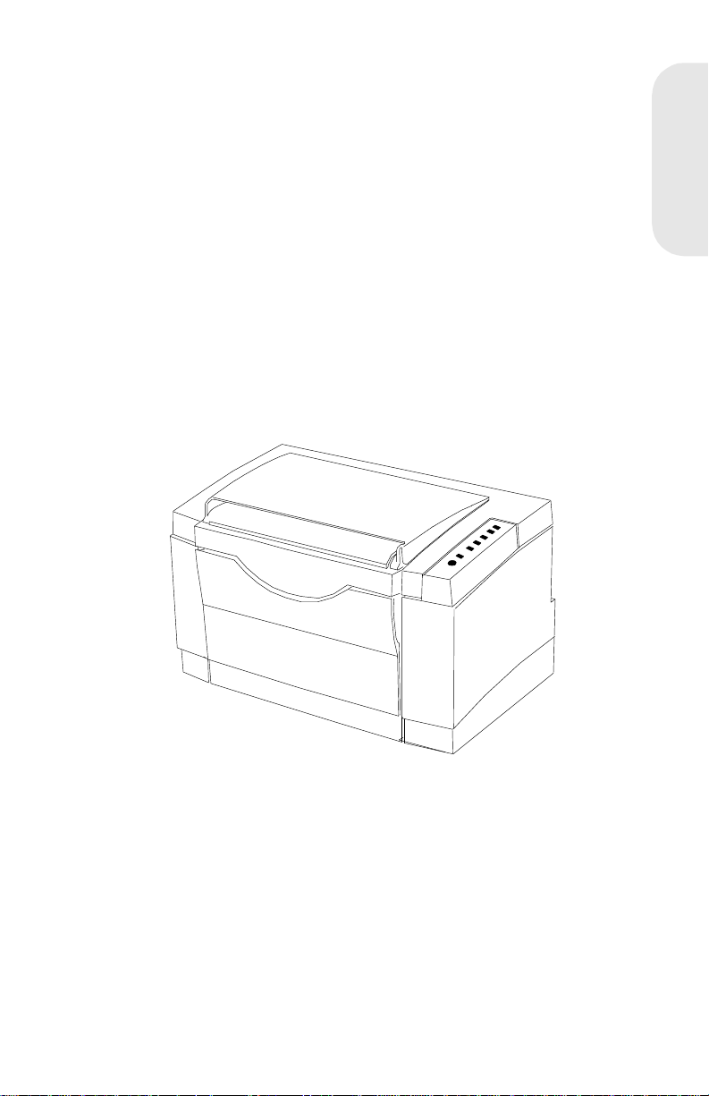
4026-0XX 1
Optra E
4026-0XX
4026-0XX
1-1
Page 9

Notes:
Laser Printer Refer ence Handbook
1-2
Page 10

4026-0XX
Diagnostics
Start
CAUTION:
interlock switch and the printhead shutter actuator at the same
. To perform some of the servic e checks and tests, such as
time
troubleshooting paper feed problems, you need to actuate the top cover
interlock switch with the covers opened or removed and power applied
to the machine. It is important for personal safety that you
FOR ANY REASON
is on.
Remove power from the printer before you connect or disconnect any
cable or electronic board or assembly for personal safety and to prevent
damage to the printer.
Use the service error code, user error message, symptom table, service
checks, and diagnostic aids to determine the corrective action
necessary to repair a malfunctioning pr int er.
The lights on the operator panel can indicate either a user error
message or service error message. When a service error occurs the
printer stops printing and all operator panel LEDs blink in a continuous
patt e rn, indicating a se rvice e rror, until the pri n t e r is powe r e d o ff. If all
operator panel LEDs are blinking, go to the “Service Error Codes” on
page 1 -5.
When a user error message occurs, one or two operator panel LEDs
are on solid or blinking. Go to the “User Error Message Table” on
page 1 -8.
If your machine does not have a service error code and does not
complete POST, go to the “POST Symptom T able” on page 1-11. If your
machine completes POST without an error, and you have a symptom,
go to the “Symptom Table” on page 1-12. Locate your symptom and
take the appropriate action.
If a service error code appears while you are working on the machine,
go to the “Service Error Codes” on page 1-5 and take the indicated
action for that error.
If your printer did not successfully complete POST, locate the symptom
in the “POST Symptom Table” on page 1-11 and take the appropriate
action.
NEVER
manually actuate or disable the top cover
DO NOT,
, disable the printhead shutter actuator when power
4026-0XX
4026-0XX
1-3
Page 11

If the printer completes all these steps and no error indications are
displayed, the printer has successfully completed the POST. If the
printer has completed POST without an error and a symptom exists, go
to the “Symptom Table” on page 1-12.
Power-On Self Test (Post)
4026-0XX
The printer performs the following Power-On Self Test when powered
on:
1. All LEDs come on solid.
2. The fan turns on for 2 seconds.
3. All the LEDs turn off.
4. The engine board checks the status of the cover interlock switch.
5. The LEDs begin to turn on then off continuously.
6. The fan turns off.
7. The engine board checks the status of the paper exit sensor.
8. The engine board checks the status of the thermistor.
9. The fuser lamp turns on.
The printer may be idle for up to 40 seconds as the fuser warms
to operating temperature. Printer idle time is shorter if the fuser is
already warm.
10. The polygon motor (printhead motor) turns on.
11. The main motor turns on.
12. The paper feed gears turn.
13. The print cartridge drive gear engages.
14. The paper feed take-up shaft and D-roll assembly rotates to
home position. (The paper feed lift plate assembly is in the down
position).
15. All the LEDs turn off.
16. Model 4026-06A, 06D - The Ready LED turns on solid and the
Data LED blinks. Go to Step 17.
Model 4026-06B, 06E - The Ready LED turns on solid and the
Data LED blinks.
• The controller board checks flash ROM installation.
• The controller board verifies that flash is formatted.
• The controller board attempts to format flash if unformatted.
• The Data LED blinks du ring format.
• The printer continues POST after format is complete.
• If format fails, a “Flash Memory Failure” error displays.
Laser Printer Refer ence Handbook
1-4
Page 12
17. The main drive motor turns off.
18. The polygon motor (printhead motor) turns off.
19. The Data LED turns off.
20. The Ready LED stays on solid.
If the printer completes all these steps and no error indications are
displayed, the printer has successfully completed the POST.
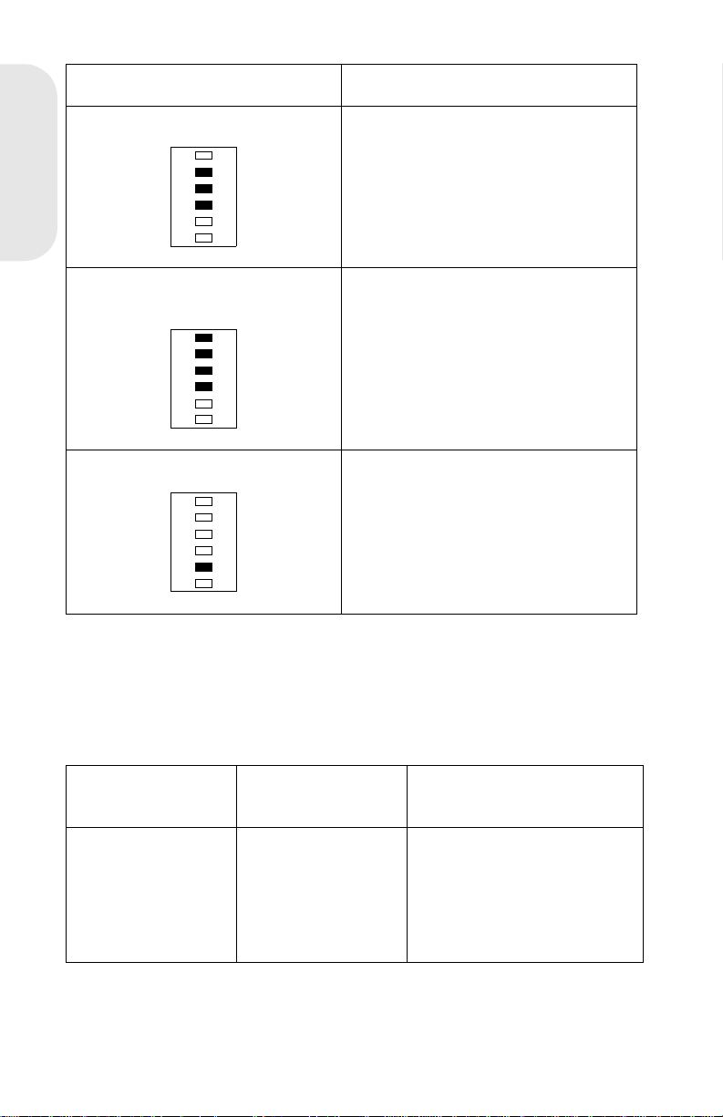
Service Error Codes
When a service error occurs the printer stops printing and all operator
panel LEDs blink in a continuous pattern, indicating a service error, until
the printer is powered off.
Press and release the operator panel button to display the service error
code. Locate the blinking LEDs in the following table and take the
indicated action.
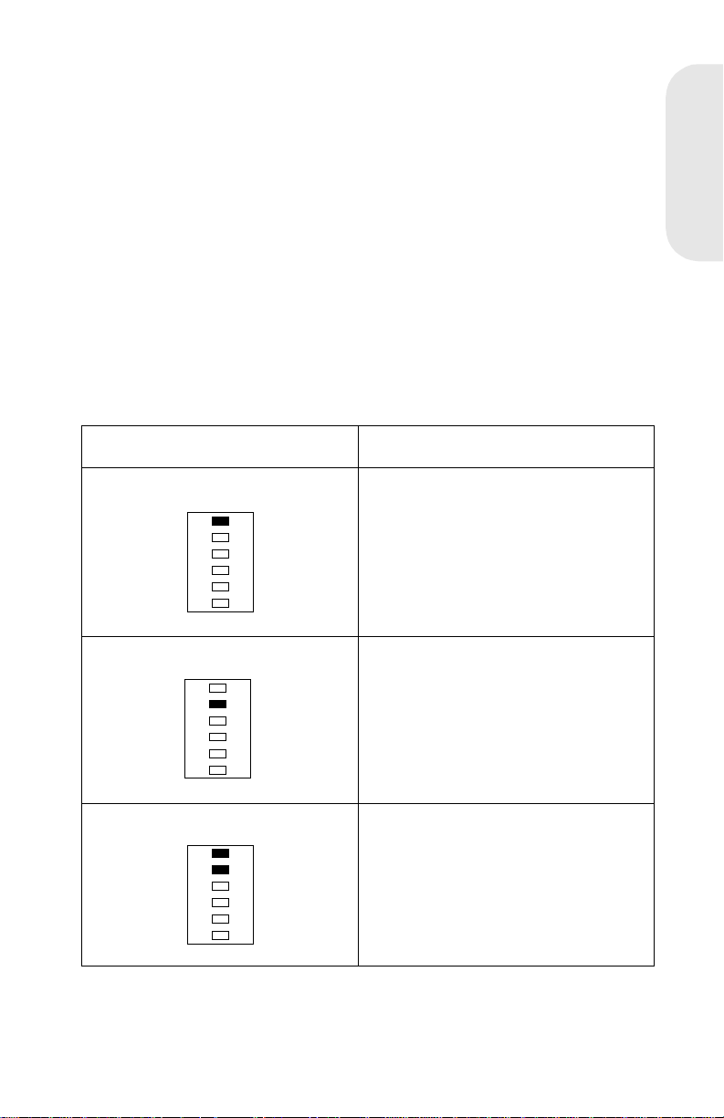
Blinking Operator Panel LED Action
Software Service Error Code Run the Printer Diagnostic Test to
diagnose between the ROM SIMM
and the control ler board. If no other
error cod e displays after the test
completes, replace the controller
board.
4026-0XX
Fuser Failure Error Refer to t he Cold Fus er Service
Check in the Service Man ual.
Mirror Motor Error The Polygon Mirror Motor is not
rotating during printing. Replace the
engine board. If t his does not c orrect
the problem, replace the printhead
assembly.
4026-0XX
1-5
Page 13
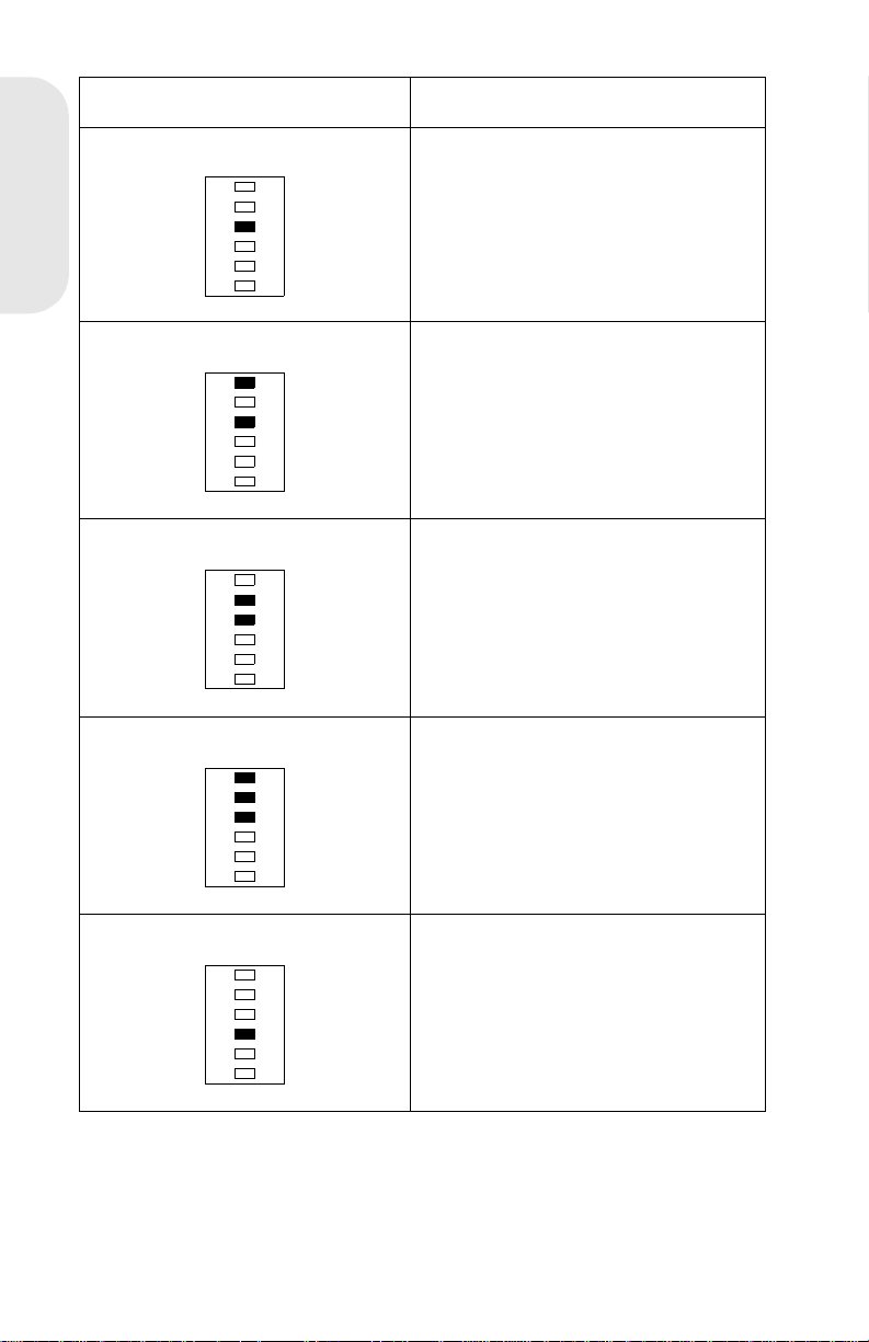
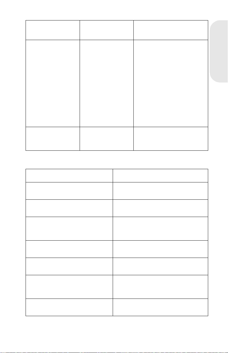
Blinking Operator Panel LED Action
Laser Diode Failure Replace the printhead assem bly. If
this does not correct the problem,
replace the engine board.
4026-0XX
Controller Card Failure Replace Controller board
Optional Memory Error Replace the op ti onal memory SI MM.
If this does not correct the problem ,
replace the controller board.
Fan Failure Error Refer to the Fan Service Check in
the Service Manual.
ROM Checksum Error Replace the ROM SIMM. If thi s does
not correct the problem, replace the
controller board.
Laser Printer Refer ence Handbook
1-6
Page 14
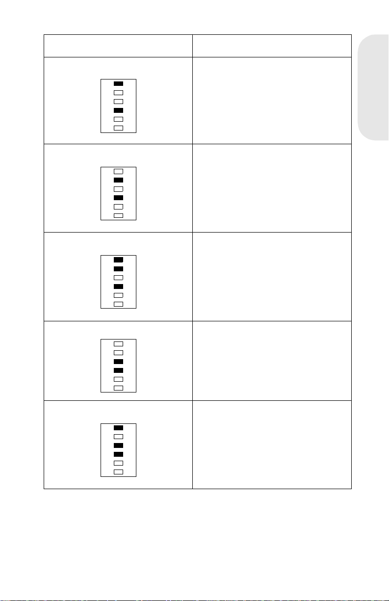
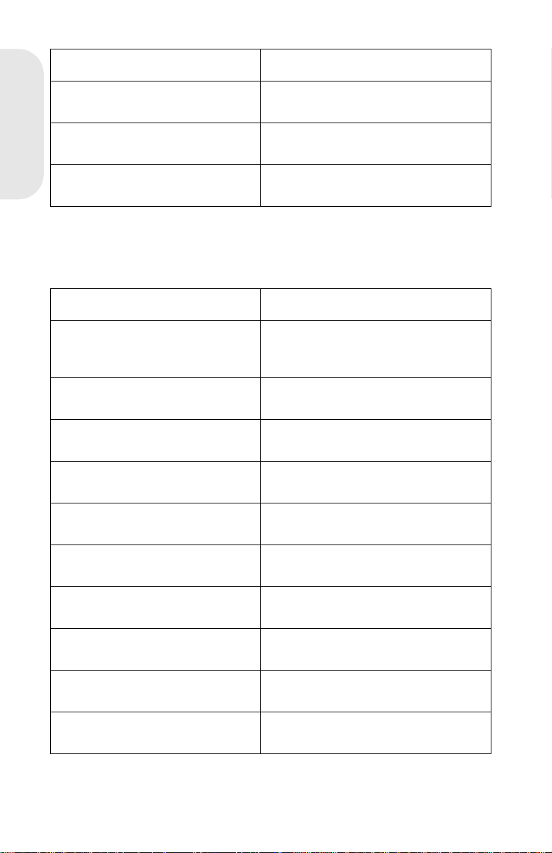
Blinking Operator Panel LED Action
Base Memory Error Replace Controll er board
NVRAM Fai lure Error Replace Controller board
ASIC Register Failure Error Replace Controller board
ASIC SRAM Fail ure Er ror Replace Controll er boar d
4026-0XX
Flash Memory Failure Error Replace the ROM SIMM w/Flas h. If
this does not cor rect the problem,
replace the controller board.
4026-0XX
1-7
Page 15
Blinking Operator Panel LED Action
Font Checksum Fail ure Error Replace the ROM SIMM . If thi s does
not correct the problem, replace the
controller board.
4026-0XX
Engine Board Communications
Failure Error
Controller SRAM Failure Error Replace Controller board
Replace the engine boar d. If this
does not correct the problem,
replace the controller board.
User Error Message Table
When a user error message occurs the printer stops printing and one or
two operator panel LEDs are on solid or blinking until the printer is
powered off. Locate the printer’s LED Status in the following table and
take the indicated action.
User Error
Message
LED Status Action
Paper Jam Paper Jam on solid Open cover and clear any
paper jams. Close the top
cover. If the error message
is still present , refer to the
Paper Feed Service Check
in the Service Manual.
Laser Printer Refer ence Handbook
1-8
Page 16

User Error
Message
Load Manual
Paper /Envel ope
LED Status Action
Load Paper blinks
and Press Button
on solid
Load media into the manual
slot and push the oper ator
panel button to resume
printing or do a front panel
reset by pressing and
holding the operator panel
button for more than three
seconds.
4026-0XX
Load Paper/Load
Env elo pe
Top Cover Open Error on solid Close the top cover. If the
Memory Full/
Complex Page/
Resolution
Reduction
Warning/Data
Transmission Error
Load Paper on
solid and Press
Button on soli d
Error on solid and
Press Button on
solid
Load media in the
appropriate pap er tr ay and
push the operator panel
button to r esum e printing or
do a front panel reset by
pressing and hol ding the
operator panel button for
more than three seconds.
error LED remains on solid
and POST does not
continue, refer to t he Cover
Interlock Service Check in
the Service Manual.
The printer memory is full or
the page is too complex to
print. The printer is forced to
reduce the resol ution of a
formatted page to 300 dpi
before pri nting, or the printer
is unable to maintain the
required data transfer rate.
Refer to the “User
Secondary Error Message”
Table in the Service Manual.
Flash Memory Full Error blinks and
Press Button on
solid
This condition only occurs
when the Flash SIMM is
installed. (4026-06B, 06E)
Refer to the “User
Secondary Error Message”
Table in the Service Manual.
4026-0XX
1-9
Page 17

User Secondary Error Message Table
Press and release the operator panel button two times to display the
user secondary error LED status. Each press and release action must
be performed within a half second. Locate the printer’s LED status in
the following table and take the indicated action.
4026-0XX
User Error
Message
LED Status Action
Complex P age Ready, Error, and
Press Button on
solid
Memory Full Ready, Data,
Error, and Press
Button on solid
Resolution
Reduction
Ready, Data
blinking and the
Error , Press But ton
on solid
Switch the printing mode to
a differ ent pri nting mode
using the Lexmark driver for
Windows, or push the
operator panel button to
resume printing, or do a
front panel reset b y pre ssing
and holding the oper ator
panel button for more than
three seconds.
Change the pri nting mode to
Quick Print Plus or reduce
the complexity of the job or
the resolution, or push the
operator panel button to
resume printing, or do a
front panel reset b y pre ssing
and holding the oper ator
panel button for more than
three seconds.
Switch from the GL/2 or
raster mode to Quick Print
Plus mode using the
Lexmark driv er f or Windows ,
or press the operator panel
button to resume printing,
or do a front panel reset by
pressing and holding the
operator button for more
than three seconds.
Laser Printe r Reference Handbook
1-10
Page 18
User Error
Message
Data Transmission
Error
LED Status Action
Data, Error, and
Press Button on
solid
Switch to Print Accelerator
using the Lexmark driver for
Windows if 2MB of memory
or more is installed, or
switch to the GL/2 printing
mode using the Lexmark
driver for Windows, or push
the operator panel button to
resume printing, or do a
front panel reset b y pressing
and holding the oper ator
panel button for more than
three seconds.
4026-0XX
Flash Memory Full Error blinking and
Press Button on
solid
This condition only occurs
when the Flash memory is
full.
POST Symptom Tabl e
Symptom Action
POST completes e xcept one or
more LEDs do not come on.
None of the LEDs come on. Refer to t he Operator Panel Service
The printer is dead (No LEDs
come on, no motor turns)
The fan does not come on. Refer to the Fan Service Check in t he
The fuser l am p does not c om e on. Refer to the Cold Fuser Service
The polyg on motor does n ot come
on.
Refer to the Ope rator Panel Service
Check in the Service Man ual.
Check in the Service Man ual.
Refer to the Low Voltage Power
Supply Service Check in the Service
Manual.
Service Manual.
Check in the Service Man ual.
Replace the printhead assembly. If
this does not fix the problem, repl ace
the engine board.
The main drive motor does not
come on.
Refer to the Main Drive Motor Service
Check in the Service Man ual.
4026-0XX
1-11
Page 19
Symptom Action
The paper feed gears do not turn. Refer to the Paper Feed Service
Check in the Service Manual.
The paper feed solenoid picks
4026-0XX
and tries to feed paper.
The toner/print cartridge gear s do
not tur n .
Refer tot he Paper Fe ed Service
Check in the Service Manual.
Refer t o the Main Driv e Motor Service
Check in the Service Manual.
Symptom Table
Locate your symptom in the following table and take the appropriate
action
Symptom Action
Dead printer Refer to the Lo w Voltage Power
Supply Service Check in the Service
Manual.
Fan not w orki ng Refer to the Fan Se rvice Check in the
Service Manual.
Fan noisy Refer to the Fan Service Check in the
Service Manual.
Fuser parts melted Refer t o the Col d Fuser Service
Check in the Service Manual.
Fuser Lamp doesn’t light Refer to the Cold Fuser Service
Check in the Service Manual.
Toner not fused to the paper Refer to the Cold Fuser Service
Check in the Service Manual.
Blank page Refer to the Print Quality Service
Check in the Service Manual.
Black page Refer to the Print Quality Service
Check in the Service Manual.
High or heavy background Refer to the Print Quality Service
Check in the Service Manual.
Offset print (image ar ound
characters)
Laser Printe r Reference Handbook
1-12
Refer to the Print Quality Service
Check in the Service Manual.
Page 20

Symptom Action
Poor image (charact ers washed
out)
Paper jams Refer to the Paper Feed Service
Main Drive Motor noisy Refer t o the Main Drive Motor Service
Main Drive Motor does not move Refer to the Main Dri ve M otor Service
Main Drive Motor runs backward Replace the Engine board.
Paper is not picked or never
leaves the primary tray
Paper is not picked or never
leaves the optional paper tray
(Tray 2)
Paper feeds continuously Refer to t he Paper Feed Servi ce
Paper fails to exit printer or st ack
in output bin
Paper skew Refer to t he Paper Feed Servi ce
Refer to the Print Quality Service
Check in the Service Man ual.
Check in the Service Man ual.
Check in the Service Man ual.
Check in the Service Man ual.
Refer to t he Paper Feed Frame
Assembly S ervice Ch eck in the
Service Manual.
Refer to the Optional Pape r Tray 2
Service Check in the Service Manual.
Check in the Service Man ual.
Refer to the Paper Feed Service
Check in the Service Man ual.
Check in the Service Man ual.
4026-0XX
Toner on the back of the page Refer to t he Transfer Assem bly
Service Check in the Service Manual.
Po or pri nt quality Refer to the Print Quality Service
Check in the Service Man ual.
Incorrect characters print Refer to the Print Quality Service
Check in the Service Man ual.
Printer not communicating with
host
White or black lines or bands Refer to the Print Quality Service
Paper wrinkled or bent Refer to the Paper Feed Service
Refer to the Parallel Port Service
Check in the Service Man ual.
Check in the Service Man ual.
Check in the Service Man ual.
4026-0XX
1-13
Page 21

Symptom Action
Top cov er wi ll not close Refer to the Cov er Interlock Service
Check in the Service Manual.
Light print Refer to the Print Quality Service
4026-0XX
Check in the Service Manual.
Laser Printe r Reference Handbook
1-14
Page 22

Diagnostics Aids
Printer Diagnostic Test
The following tests run sequentially when performing this test:
Standard Memor y Test
Optional Memor y Test
Microcode Check
LED Test
Read/Write ASIC Register Test
Read/Write ASIC SRAM Test
Read/Write controller board SRAM Test
Perform the following steps to run the Printer Diagnostic Test:
1. Tur n t he prin ter off.
2. Open the top cover.
3. Press and hold the operator panel button as you turn on the
printer. Release the button once the printer’s indica tor lights
come on.
4. Wait until the Error LED (top cover open indication) comes on.
5. Close the top cover.
6. The Ready LED comes on solid and the Data LED blinks. (This is
the printer Busy Mode indication).
7. If all the diagnostic tests run correctly, the Ready LED goes off
and the Data LED continues to blink. If a test fails, the error light
pattern for the service error code displays on the operator panel.
4026-0XX
4026-0XX
1-15
Page 23

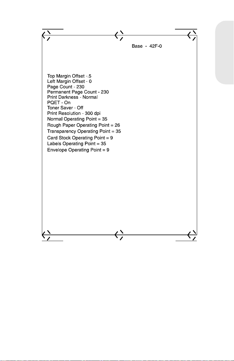
Service Diagnostic Test Page
The service diagnostic test page includes registration marks to aid in
adjusting print registration and also includes the installed printer base
code level. The service test page displays the user default v alues for t he
following:
4026-0XX
Top M argin Offset
Left Margin Offset
Printer Page Count
Permanent Page Count
Print Da rk n es s Setting
PQET Setting (on/off)
Tone r Saver (on/off)
Print Re s olu t ion
Perform the following steps to print the Service Diagnostic Test Page:
1. Tur n the pr inter off.
2. Open the top cover.
3. Press and hold the operator panel button as you turn on the
printer.
4. Wait until the Error LED comes on solid.
5. Close the top cover.
6. The Ready LED is on solid and the Data LED blinks continuously.
7. When the test is complete the Ready LED goes off and the Data
LED continues to blink.
8. Press the operator panel button briefly.
9. The Ready and Data LEDs blink and the Service Diagnostic T est
Page prints. The test page requires several seconds to start
printing.
10. When the test page has finished printing the Ready LED comes
on solid and Data LED goes off.
Note:
automatically exits the diagnostic mode and returns to the normal
mode.
After the diagnostic test page prints, the printer
Laser Printe r Reference Handbook
1-16
Page 24
4026-0XX
4026-0XX
1-17
Page 25
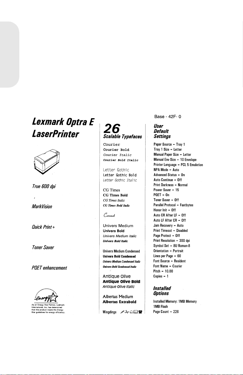
User Mode Print Test Page
The User Mode Print Test Page displays the user default values,
installed options, printer features, various typefaces, and the installed
printer base code level.
1. Be sure the Ready LED is on solid (printer is in the ready state).
4026-0XX
2. Press and release the operator panel button.
3. The Ready and Data LEDs blink continuously.
4. The test page prints and the operator panel Ready LED comes
on solid and the Data light turns off.
5. The printer returns to the ready state.
Laser Printe r Reference Handbook
1-18
Page 26

Configuration Mode
The configuration mode gives the ability to set the following printer
functions through the operator panel:
Hex Trace
NPA Mode (Parallel)
Parallel Protocol
Advanced Status
PPDA Activated
Auto CRLF/LFCR
Perform the following steps to enter the configuration mode:
1. Tur n t he prin ter power off.
2. Open the top cover.
3. Turn the printer power on.
4. Top Cover Open (Error LED on) is displayed on the operator
panel.
5. Double-click the operator panel button.
Note:
solid. The Data, Load Paper, Paper Jam, Er ror and Press Button are off.
Note:
mode. Repeat the steps to re-access the configuration mode.
Configuration Mode Operator Panel Overlay
The following overlay indicates the operator panel LED and button
designations when in the configuration mode.
The printer is in the configuration mode. The Ready LED is on
Closing the top cover causes the printer to exit the configuration
4026-0XX
Hex Trace
NPA Mode
Parallel Protocol
Advance St a tus
CRLF/LFCR
Off/On/Auto
Press three secon ds to save
4026-0XX
1-19
Page 27

Operator Panel Configuration Mode Button Definition
Term Description Result
Brief Button Press Press the operator
4026-0XX
Long Button Press Press and hold the
Double-Click Button
Press
panel but ton n o longer
than three seconds.
operator panel button
for more than three
seconds.
Press and release t he
operator panel button
two times. E ac h
press and release
action must be
performed within a
half second.
This action moves
through the
configurat ion mode
value list.
This action sel ects
and save s the value
for the menu it em
displayed. To indicate
that the setting i s
save d, it is displayed
on the operator pane l.
This action moves
through the
configurat ion mode
value list.
Laser Printe r Reference Handbook
1-20
Page 28

Hex Trace
Use Hex Trace to isolate the cause of print problems. When a job is
printed, the printer operator panel displays the Hex Trace indication,
(Ready LED blinking), showing that the printer remains in the Hex Trace
mode. Tu rn the printer power off or do a front panel reset (long button
press) to exit the Hex Trace mode.
Perform the following steps to enter the Hex Trace mode:
1. Enter the configuration mode.
2. Do a brief button press.
3. The Ready LED is on and the Press Button (Off/On/Auto) is on or
off indicating the value selected. A brief button press causes the
printer to cycle through the valid settings for Hex Trace and the
Press Button LED turns on or off.
Operator Panel LED Status Action
4026-0XX
Off/On/Auto LED and Hex Trace
LED is off
Off/On/Auto LED and Hex Trace
LED is on
A long button pr ess causes the
printer to exit configurat ion mode
and enter the normal printi ng mode
or a demo printing mode.
A double-click button press causes
the next menu item, NPA mode, to
display
A long button pr ess causes the
printer to e xi t the config urat ion mode
and enter Hex Trace mode.
A double-click button press causes
the next menu item, NPA mode, to
display .
4. Press and hold the button until the Saved setting indication, (all
LEDs on solid) is posted.
5. When the Error LED comes on, close the top cover.
6. The printer completes POST with the Ready LED blinking
indicating the printer is in the Hex Trace mode.
7. Do a double-click to proceed to the next mode. Do an operator
panel reset or turn the printer off to exit the Hex Trace mode.
4026-0XX
1-21
Page 29

Restoring Factory Defaults
Restoring factory defaults returns the printer settings to the original
factory sett ing s.
Perform the following steps to invoke factory defaults:
1. Turn the printer power off.
4026-0XX
2. Open the top cover.
3. Tur n t he printer power on. The printer star ts POST.
4. The operator panel Error LED comes on solid.
5. Press and hold the operator panel button until all the LEDs are
on solid indicating the printer is restoring factory defaults.
6. Release the button. The printer indicates the operation is
complete by turning all the LEDs off except the Error LED.
7. The configuration mode can be selected by doing a brief button
press or closing the top cover which causes the printer to enter
either the normal mode or the demo mode.
Laser Printe r Reference Handbook
1-22
Page 30
Connectors
Low Voltage Power Supply
Connector Pin No. Signal
CN1 Engine Board
CN2 Fuser Lamp/
Thermal Fuse
1 +24 V dc
2GND
3GND
4 +5 V dc
5FUSER LAMP*
1HEAT N
2 NO CONNECTION
3HEAT L
High Voltage Power Supply
Connector Pin No. Signal
CN1 Engine Board
T
TRET
1HV C
2HV T*
3 HV SEL 2*
4 HV SEL 1*
5HV B
6 BIAS MON
7GND
8 +24 V dc
T HV to TRANSFER CORONA
CHARGE
TRET HV to TRANSFER CORONA
HOUSING
4026-0XX
4026-0XX
1-23
Page 31

Engine Board
CN1A Controller Board
Pin No. Signal Pin No. Signal
1 NO CONNECTION 16 CMD*
4026-0XX
2 NO CONNECTION 17 CTBSY*
3 NO CONNECTION 18 PRINT*
4 NO CONNECTION 19 SRCLK*
5GND 20GND
6 RESET* 21 GND
7 GND 22 VIDEO*
8 GND 23 +5 V dc
9GND 24GND
10 HSYND* 25 +5 V dc
11 EPRDY* 26 GND
12 PRRDY* 27 +5 V dc
13 TDD* 28 CPRDY*
14 ETBSY* 29 +5 V dc
15 STS* 30 TEST*
Connector Pin Signal
CN2A Thermistor
CN3A Paper Entry
Sensor and Paper
T ake-up Solenoid
Laser Printe r Reference Handbook
1-24
1 THERMISTOR
2 +5 V dc
1 ANODE (PC1)
2GND
3PC1*
4 NO CONNECTON
5 +24 V dc
6 FEED1*
Page 32

Connector Pin Signal
CN4A HVPS
CN5A Laser Diode
Drive Board
CN6A Main Motor
CN7A LVPS
CN8A Paper Exit
Sensor
1HV C
2HV T*
3 HV SEL2*
4 HV SEL1*
5 HV B
6 BIAS MON
7GND
8 +24 V dc
1 S SCAN
2CO
3 LD APC2 (LDVR2)
4 LD APC1 (LDVR1)
5GND
6 L DATA*
7 +5 V dc
1 PHASE A
2 PHASE A*
3 PHASE B
4 PHASE B*
1 +24 V dc
2GND
3GND
4 +5 V dc
5FUSER LAMP*
1 ANODE (PC3)
2GND
3PC3*
4026-0XX
4026-0XX
1-25
Page 33

Connector Pin Signal
CN9A 2nd Paper Tra y
(Option)
4026-0XX
CN10A Polygon
Motor
CN11A Fan Motor
1 +24 V dc
2 FEED 2*
3 NO CONNECTION
4+5 V dc
5GND
6 P EMP2
7 PSIZED
8 2NDBIN*
9 MM/INCH
10 CHECK0*
11 CHECK1*
12 CHECK2*
1 NO CONNECTION
2 +24 V dc
3GND
4+5 V dc
5 POLYGON CONTR OL
1FAN*
2 +24 V dc
Laser Printe r Reference Handbook
1-26
Page 34

Second Paper Tray Sensor Board (Option)
Connector Pin No. Signal
CN1A Engine Board
CN3A Paper Take-up
Solenoid - 2nd Paper
Tray (Option)
1 CHECK2*
2 CHECK1*
3 CHECK0*
4 MM/INCH
5 2NDBIN*
6 PSIZEO
7 P EMP 2
8GND
9 +5 V dc
10 NO CONNECTION
11 FEED2*
12 +24 V dc
1 +24 V dc
2 FEED2*
Controller Board
4026-0XX
Connector Pin No. Signal
J5 Op er ator Panel
1GND
2 +5 V dc
3OP DAT
4OP CLK
5 OP BTN 1
6 OP BTN 2
4026-0XX
1-27
Page 35

J4 Engine Board
Pin No. Signal Pin No. Signal
1 NO CONNECTION 16 CMD
2 NO CONNECTION 17 CTBSY
4026-0XX
3 NO CONNECTION 18 PRINT
4 NO CONNECTION 19 SRCLK
5GND 20GND
6 RESET* 21 GND
7 GND 22 R VIDEO*
8 GND 23 +5 V dc
9GND 24GND
10 RHSYNC* 25 +5 V dc
11 EPRDY* 26 GND
12 PRRDY* 27 +5 V dc
13 TOD* 28 CPRDY
14 ETBSY* 29 +5 V dc
15 STS* 30 NO CONNECTION
Connector Pin No. Signal
J3 Pullup Power
J2 Parallel Port
Pin No. Signal Pin No. Signal
1 RSTROBE* 19 GND
2D0 20GND
3D1 21GND
4D2 22GND
5D3 23GND
6D4 24GND
7D5 25GND
Laser Printe r Reference Handbook
1-28
1+5 V dc
2 +5 V dc JUMPER
3 NO CONNECTION
Page 36

J2 Parallel Port (Continued)
Pin No. Signal Pin No. Signal
8D6 26GND
9D7 27GND
10 RACK* 28 GND
11 RBUSY 29 GND
12 RPERROR 30 GND
13 RSELOUT 31 RINIT*
14 RAUTOFD* 32 RFAULT*
15 GND 33 GND
16 GND 34 GND
17 GND 35 GND
18 PLH 36 RSELECTIN*
Paper Exit Sensor
Connector Pin No. Signal
CN3S Engine Board 1 ANODE (PC3)
2GND
3PC3*
4026-0XX
Paper Entry Sensor
Connector Pin No. Signal
CN1S Engine Board
1PC1*
2GND
3 ANODE (PC1)
Paper Feed Solenoid
Connector Pin No. Signal
CN2S Engine Board
1 +24 V dc
2 FEED1*
4026-0XX
1-29
Page 37

Parts Catalog
Covers
P/N Description
4026-0XX
69G8341 Left Side Cover
69G9969 Cover, Cable
69G8301 Top Cover
69G8306 Fan Cover
69G8305 Fan
69G9990 Label, S/N Bla nk
69G8340 Exit Paper Tray
69G8303 Cover Release Assembly
69G8302 Printhead Interlock Actuat or
69G8396 Operator Panel Assembly inc. English Overlay
69G9981 Operator Panel Assembly inc. Overlay W.T. Kit
69G8342 Right Side Cover with shield
69G9690 Logo, Optra E
69G8344 Input Paper Tray
69G8343 Front Cover
69G8337 Gear, 15T
69G8338 Bushing
69G9999 Board, PWB-R
69G9971 Exit Paper Feed Roller/Clip Assembly
69G8336 Exit Paper Feed Roller/Shaft Assembly
11A7443 Logo, Optra Ep (Models 06D and 06E)
Frame
Part
Number
69G9962 Motor, Main Drive
69G9691 Left Side Pla te Motor Bracket
69G8345 Left Side Pla te
69G8346 Guide, photoconductor unit
69G8347 Guide, Toner Cartridge/Photoconductor Unit
11A7420 Bracket, Printhead Mounting
69G8358 Terminal, Rt Side Ground LVPS to Bd Cage
69G8360 Terminal, Rt Side Photoconductor Unit Ground
69G8361 Terminal, Rt SIde, Photoconductor Unit Charge Bias
69G8362 Terminal, Rt Side Toner Cartridge
Laser Printe r Reference Handbook
1-30
Description
Page 38

Frame (Continued)
Part
Number
69G8357 Spring, Rt Side Frame, Cartridge Latching
69G8359 Terminal, Rt Side Ground HVPS to Bd Cage
69G9982 Terminal, Ground
11A7424 Terminal, Left Side Plat e to LVPS
11A7425 Terminal, Left Side Plat e to Li ft Plate
69G8377 Clutch Cam Assembly
69G8379 Bushing
69G8393 D-Roll Shaf t
69G9991 Pin, D-Roll Shaft
69G8375 D-Roll
69G8363 Rubber Foot
Description
Printhead
Part
Number
69G8364 Printhead Assembly 600 dpi
Description
Paper Feed Input Tray
Part
Number
69G8365 Paper Feed I nput Tray Assembly
69G8367 Pressure Spring
69G8394 Guide Plate, Manual Feed
69G8366 Guide, Movable Paper
11A7419 Lift Plate Assembly
Description
4026-0XX
4026-0XX
1-31
Page 39

Paper Feed Frame
Part
Number
69G8368 Paper Feed Frame Assembly
69G8369 Gear, 16T Paper Feed
4026-0XX
69G8371 Sensor, Paper Entry
11A7409 Cable, Input Sensor/Solenoid to Engine Board
69G8372 Flag, Paper Entry Sensor
69G8373 Separator, Paper
11A7442 Paper Feed Pressure Roller Assembly
69G8374 Terminal, Solenoid Ground
69G8370 Solenoid, Paper Feed
Description
Fuser
Part
Number
69G8312 Fuser Assembly, 120 V ac
69G8313 Fuser Assembly, 220/230 V ac
69G8328 Lower Fuser Assembly
69G8331 Sensor, Paper Exit
11A7408 Cable, Paper Exit Sensor
69G8332 Flag, Paper Exit Sensor
11A7423 Spring, Exit Sensor Flag
69G8333 Separator, Paper Hot Roll
11A7421 Separator Roll
69G8314 Thermal Fuse
69G8327 Terminal, Fuser Lamp Right Side
69G8329 Terminal, Thermal Fuse
69G9973 Spring, Backup Roll
11A7422 Holder, Backup Roll Spring
69G8315 Fuser Lamp, 120 V ac
69G8316 Fuser Lamp, 220/230 V ac
69G9694 G-Ring, Hot Rol l
69G9695 Bearing, Hot Roll
69G9978 Backup Roll
69G9977 Hot Roll
69G8317 Thermistor
69G8330 Separator, Paper
69G8325 Cable, Fuser Lamp
69G9979 Terminal, Fuser Lamp/Thermal Fuse
Description
Laser Printe r Reference Handbook
1-32
Page 40

Fuser (Continued)
Part
Number
69G8326 Terminal, Fuser Lamp Left side
69G8318 Upper Fuser Assembly
69G9697 Lever, Fuser Driv e
69G8323 Spring , Inside
69G9698 Arm, Fuser Driv e
69G8324 Spring, Outside
69G9699 Holder, Fuser Drive
11A7431 Transfer Corona cleani ng tool
Description
Electronics
Part
Number
69G8380 Power Supply, 110 V ac
69G8382 Power Supply, 220/230 V ac
1339526 Power Cord; U.S.
69G8381 Fuse, 125 V ac, 5 A
69G9976 Fuse, 250 V ac, 3.15 A
69G9972 Rear Frame
69G8356 Cover, High Voltage Power Supply
69G8383 Board , Hig h Voltage Power Supply
11A7410 Cable, HVPS to Engine Board
69G8385 Cable, 2nd Paper Drawer
11A7406 Cable, Transfer Assembly to HVPS
11A7417 Termi nal, Rear Frame Ground to Control Board Cage
11A7418 Cover, LVPS Edge
69G8386 Controller Board Brac ket W/O Cage
69G9985 Controller Board Cage
11A7439 Controller Boar d W/O R O M SIMM, Mod els 06A, 06B
69G8262 Controller Board, W/O ROM SIMM, Models 06D, 06E
11A7433 Screw, 4-40 Control Board To Board Cage
69G9983 ROM SIMM, Model 06A (W/O Flash)
69G9984 RO M SIMM W/F lash, Model 06B, 06E
11A7272 ROM SIMM, Model 06D, W/OFlash
11A7271 ROM SIMM, Model 06E, W/Flash
69G8384 Engine Board
Description
4026-0XX
4026-0XX
1-33
Page 41

Transfer Assembly
Part
Number
69G8307 Transfer Assembly
69G8310 Right Transfer Frame Guide
4026-0XX
69G8311 Spring, Right Transfer Guide
69G9968 Transfer Corona Assembly
69G9967 Spring, Left Transfer Guide
69G8308 Left Transfer Frame Guide
69G8309 Gear, 18/21T
Description
Option - Second Paper Drawer
Part
Number
69G9929 Frame, Base
69G9927 Foot, square rubber
11A7416 Foot, round rubber
69G9926 Right Side Cover
69G9937 Lift Plat e Assembly
69G9928 Tray, Paper
11A7428 Pad
11A7429 Label, Paper Set
69G9933 Adjustable Paper Guide
11A7430 Regulating Plate, paper guide
69G9938 Spring, Lif t Plate
69G9925 Left Side Cover
69G9931 Holder, Roller
69G9930 Rolle r
69G9942 Stud, Solenoid Mounting
69G9965 Lever , Lift Plate Release
69G8370 Solenoi d
69G9958 Lever, Knockoff
69G9963 Button, Lift Plate Release
69G9943 Bracket
69G9945 Gear, 13/45T
69G9944 Gear, 41T
69G9946 Clutch Assembly, complete
69G9947 Gear, 28T
69G9949 Ratchet
11A7414 Collar, clutch
Description
Laser Printe r Reference Handbook
1-34
Page 42

Option - Second Paper Drawer (Continued)
Part
Number
69G9955 Shaft, D-Roll
69G9991 Pin, D-Roll Shaft
69G9957 Bushing, D-Roll Shaft
69G9956 D-Roll
69G9953 Gear, 14T
69G9952 Bushing, Paper Feed Shaft, Outside
69G9950 Paper Feed Shaf t W/Roller
69G9951 Bushing, Paper Feed Shaft, Inside
69G9959 Holder, Sensor Flag
69G9960 Sensor Flag
69G9935 Ground Term inal
69G9934 Sensor/Interface Board
69G9940 Cover, Front.
69G9939 Paper Feed Assembly, complete
11A7427 Guide Plate
Description
Option - SIMMS
Part
Number
1364936 Memory SIMM, 1MB
1364906 Memory SIMM, 2MB
1364907 Memory SIMM, 4MB
Description
4026-0XX
Miscellaneous
Part
Number
69G9986 Parts Packet, C-Clips
69G9987 Parts Pack et, Springs
69G9988 Parts Packet, Fuser Gears
69G9989 Parts Packet, Paper Feed Gears
69G9974 Parts Packet, Screws
11A7436 Parts Packet, Second Paper Dra wer Springs
11A7434 Parts Packet, Second Paper Dra wer Screws
Description
4026-0XX
1-35
Page 43

4026-0XX
Laser Printe r Reference Handbook
1-36
Page 44

4027-04W 2
Winwriter 200
4027-04W
4027-04W
2-1
Page 45

Notes:
Laser Printer Refer ence Handbook
2-2
Page 46

4027-04W
Diagnostics
Start
Caution:
switch and the print head shutter actuator at the same time
To perform some of the ser vice checks and tests, such as
troubleshooting paper feed problems, you will need to actuate the top
cover interlock switch with the covers opened or removed and power
applied to the machine. It is imperative that you
REASON
Use the error code/message table, symptom table, and diagnostic aids
in this chapter to determine the corrective action necessary to repair a
malfunctioning printer.
If an error code or message is displayed on the host display, locate it in
the Error Message Table on the next page and take the appropriate
action.
If an alert message appears on the host display and the printer status
light is flashing rapidly and continuously, go to the “Printer Status Light
Table” on page 2-5.
If your machine does not have an error code/message and does not
complete POST, go to “Printer Status Light Table” on page 2-5. If your
machine makes it through POST without an error, and you have a
symptom, go to “Symptom Table” on page 2-8, locate your symptom
and take the appropriate action.
If an error code/message appears while you are working on the
machine, go to the Error Message Tab le and take the indicated action
for that error.
Note: For all 9XX errors the 4027-04W front cover LED will blink fast,
and the error code will be displayed on the host display. The last error
will be logged in the WPS.INI file.
NEVER
, defeat the print head shutter actuator when power is applied.
manually actuate or defeat the top cover interlock
.
DO NOT, FOR ANY
4027-04W
4027-04W
2-3
Page 47

Error Message Table
Error Code/
Message
[Error 920 Fuser
Temp]
[Error 930] Mirror
Motor]
[Error 940 Laser
Failure]
[Error 950
Controller Board]
4027-04W
[Error 951
Controller Board]
[Error 952
Controller Board]
[Error 953] Replace the cont roller board.
[Error 954] The engine board det ected an inv alid command.
[Error 970 Fan
Failure]
Action
Refer to the Cold Fuser Service Check in the
Service Manual.
The Polygon motor is not rotating during printing.
Replace the engine board. If this does not fix the
problem, repl ace the print head assembly.
Replace the print head assem bly. If this does not fix
the problem, replace the engine board.
Defective ASIC. Replace the controller board.
Basecode Check sum Err or. Replac e the controller
board.
DRAM failure. Replace the controller board.
Check: Engine Boar d, LVPS-to-Engine Board
Cable.
[Error 960 Memory] Base DRAM failure. Remov e the memory option. If
the problem remains, replace the controller board. If
you still have the problem, replace the memory
option.
[Error 980 ROM
Checksum]
[Memory Full]
(WPS Msg)
[Complex Memory
Page]
(WPS Msg)
Laser Printer Refer ence Handbook
2-4
Replace EPR OM s, or MROM if i nstalled. If this does
not fix the problem, replace the contr oller board.
This error occurs when the page memory is full.
Inform the customer that more memory is needed
for the appl ication, or that some of the dat a m ust
come off the page.
This error occurs when too complex a page is
printed. Some dat a could b e mis placed on the page .
More memory is needed for the application.
Page 48

.
Printer Status Light Table
Status Action
Add XXX Paper
(Audible: Add
paper to printer)
Clear Paper Jam
(Audible: Paper
jam)
Cover Open
(Audible: Close
printer cover.)
Note:
The printer status light will blink slowly and continuously until the
Printer is out of paper. Add paper, then if the error
remains, refer to the Paper Feed Take-Up Shaft
Service Check in the Service Manual.
Refer to t he Paper Feed Servi ce Check in the
Service Manual.
Close the top c over. If the error remains, refer to the
Cove r Int erl ock Service Check in the Service
Manual.
problem is corrected. An alert message or audio message may occur if
selected in WPS Setup.
4027-04W
4027-04W
2-5
Page 49

Power-On Self Test (POST)
When you turn the printer on, it performs a Power-On Self Test. Check
for correct POST functioning by observing the following:
1. The status LED comes on solid.
2. The fan turns on for 2 seconds.
3. The engine board checks the top cover interlock switch.
4. The engine board checks the fuser thermistor.
5. The engine board checks the exit sensor.
6. The fuser lamp turns on.
Note:
warms to operating temperature. Printer idle time is shorter if the
fuser is already warm.
7. The fuser lamp turns off.
4027-04W
8. The polygon motor turns on.
9. The main motor turns on.
10. The paper feed gears turn.
11. The print cartridge drive gear engages.
12. The paper feed solenoid picks.
13. The paper feed take-up shaft assembly rotates to home position.
(The paper feed lift assembly is in the down position.)
14. The status LED remains on.
If the printer completes all these steps and no error messages are
displayed, the printer has successfully completed the POST. If your
printer has completed POST, go to the Symptom Table.
If your printer did not complete POST, locate your symptom in the
POST Symptom Tab le on the following page, and take the appropriate
action.
The printer may be idle for up to 60 seconds as the fuser
POST Symptom Table
Symptom Action
POST completes,
but the LED does
not come on
Dead machine Refer to the Low Voltage Power Supply Service
Fan not w orki ng Refer to the Fan Service Chec k in the Service
Laser Printer Refer ence Handbook
2-6
Refer to the Operator Panel Service Check in the
Service Manual.
Check in the Service Manual.
Manual.
Page 50

POST Symptom Table
Symptom Action
Fuser Lamp does
not light
Main motor not
working
Polygon motor not
working
Paper Feed Gears
not turning
Paper Feed
Solenoid not
picking up
Status Light starts
blinking quickly
before POST has
completed
Status Light starts
blinking slowly
before POST has
completed
Refer to the Cold Fuser Service Check in the
Service Manual.
Refer to the Main Motor Service Check in the
Service Manual.
Replace the engin e board. If you still have the
problem, replace the print head assem bly.
Refer to t he Paper Feed Servi ce Check in the
Service Manual.
Refer to the P aper Take-Up Solenoid Service Check
in the Service Manual.
A 9XX error code should appear i n the WPS dial og
box on the host displ a y. Check the Print Manager f or
the error code. If it is not there, go to the “WPS .INI
File” on page 2-11.
Check the host display for an alert message in the
WPS dialog box.
4027-04W
4027-04W
2-7
Page 51

Sympto m Table
Symptom Action
Dead machine Refer to the Low Voltage Power Supply Service
Check in the Service Manual.
Fan not w orki ng Refer to the Fan Service Chec k in the Service
Manual.
Fan noisy Refer to the Fan Service Check in the Servic e
Manual.
Fuser parts melted Refer to the Hot Fuser Service Check in the Service
Manual.
Fuser Lamp
4027-04W
doesn’t light
Toner not fused to
the paper
Blank Page Refer to the Print Qual ity Service Check in the
Paper Jams Refer to the Paper Feed Service Check in the
Main Motor noisy Refer to the Mai n Motor Service Check in the
Main Motor
doesn’t move
Main Motor runs
backward
Paper isn’t picked
or never leaves
the tray
Paper feeds
continuously
Paper fails to exit
printer or stack
Refer to the Cold Fuser Check in the Service
Manual.
Refer to the Cold Fuser Check in the Service
Manual.
Service Manual.
Service Manual.
Service Manual.
Refer to the Main Motor Service Check in the
Service Manual.
Replace the engine boar d.
Refer to the Paper Fe ed Take-Up Shaft Service
Check in the Service Manual.
Replace the engine boar d.
Refer to the Paper Feed Service Check in the
Service Manual.
Paper skew Refer to the Registration Service Check in the
Service Manual.
Registration Refer to the Registration Service Check in the
Service Manual.
Laser Printer Refer ence Handbook
2-8
Page 52

Symptom Table
Symptom Action
Toner on the back
of the page
Po or pri nt quality Refer to the Print Quality Service Check in the
Incorrect
characters print
Printer not
communicating
with host
Horizontal black
band
Paper wrinkled or
bent
Top cover will not
close
Refer to the Transfer Service Check in the Service
Manual.
Service Manual.
Refer to the Print Qu ali ty Service Check in the
Service Manual.
Refer to the Parallel Port Service Check in the
Service Manual.
Refer to the Print Qu ali ty Service Check in the
Service Manual.
Refer to t he Paper Feed Servi ce Check in the
Service Manual.
Refer to the Top Cover Service Chec k in the Service
Manual.
4027-04W
4027-04W
2-9
Page 53

Diagnostic Aids
Customer Test Page (From WPS)
Use this test to check print and graphics quality. Running the print test
resets temporary settings to the printer default settings and deletes all
macros and downloaded fonts.
To ru n the Print Test:
1. Tur n the pr inter on.
2. Select [Test Printer] from the WPS Setup Screen in Print
Manager.
3. One test page prints.
The printer returns to the default settings after the test page prints.
4027-04W
Customer Test Page (Stand Alone)
Use this test to check print and graphics quality. Running the print test
resets temporary settings to the printer default settings and deletes all
macros and down-loaded fonts.
To ru n the Print Test:
1. Open the top cover .
2. Tur n t he printer on.
3. After the printer status light starts blinking, close the top cover.
4. One test page prints after POST completes.
The printer returns to the default settings after the test page prints.
Developed Image Test
This test allows you to examine the image on the photoconductor and
may be used to diagnose print quality problems. You may need to do
this procedure several times to get the timing correct.
To run the Developed Image Test :
1. Run the Customer Test Page (Stand Alone).
2. Tur n t he printer off while it is printing.
3. Remove the print cartridge and look at the image on the
photoconductor.
Laser Printe r Reference Handbook
2-10
Page 54

WPS.INI File
This file can be used to check for the last error code, date and time of
the last error sent from the printer to WPS.
1. Select File Manager from the Microsoft Windows Main Menu
(double click with mouse).
2. Select Fixed Disk WPS installed on.
3. Select Windows from DIR list.
4. Select WPS.INI from Files list (double click with mouse).
5. The Notepad program displays the WPS.INI file. Scroll down until
you see:
SERVICEERROR=9xx
SERVICED ATE=MM/DD/ YY TIME HH:MM:SS AM OR PM
4027-04W
4027-04W
2-11
Page 55

Connectors
Low Voltage P ower Supply
P/N Signal
CN1 Fan
CN2 Main Motor
4027-04W
CN3 Engine Board
CN4 Cover SW
1F
2 +12VDC
1M
2M
3M
4Motor
5 SW12VDC
1 GND +5.1VDC
2 +5.1VDC
3 GND +12VDC
4 SW12VDC
5 Fuser Lamp
6 Fan Motor
7 Main Motor
8 Main Motor
9 Main Motor
10 Main Motor
1 +12VDC
2 SW12VDC
an Motor
otor
otor
otor
Laser Printe r Reference Handbook
2-12
Page 56

High Voltage Power Supply
P/N Signal
CN1 PF Solenoid
CN2 Engine Board
Engine Board
CN1 LVPS
CN2 Thermistor
CN3 Exit Sensor
1 SOL ON
2 +12VDC
1 GND1
2
3 +5.1VDC
5 +12VDC
6 GND2
7
8
9 SOL ON
P/N Signal
1 GND1
2 +5.1VDC
3 GND2
4 +12VDC
5 Fuser Lamp
6Fan On
7 Main Motor
8 Main Motor
9 Main Motor
10 Main Motor
1 Thermistor
2 +5.1VDC
1 +5.1VDC
2 GND1
3 Exit Sensor
4027-04W
4027-04W
2-13
Page 57

P/N Signal
CN4 HVPS
CN5 Printhead
4027-04W
1 GND1
2 Input Sensor
3 +5.1VDC
4 +12VDC
5 GND2
6Drum Chg On
7Ter Roll On
8 DOC Blade
9PF SOL ON
1POL LOCK
2 P/H Select
3 POLY MTR CLK
4 POLY MTR ON
5 GND2
6 +12VDC
7 +5.1VDC
8LDATA
9‘ GND1
10 LDVR1
11 LDVR2
12 LDLVL
13 SSCAN
CN6 Controller Board
P/N Signal P/N Signal
1LED1 16CMD
2 N/C 17 CTBSY
3N/C 18Print
4 GND1 19 SRCLK
5 GND1 20 GND1
6 Reset 21 GND1
7 GND1 22 Video
Laser Printe r Reference Handbook
2-14
Page 58

CN6 Controller Board (Continued)
P/N Signal P/N Signal
8 GND1 23 +5.1VDC
9 GND1 24 GND1
10 RHYSNC 25 +5.1VDC
11 EPRDY 26 GND1
12 PRRDY 27 +5.1VDC
13 TOD 28 CPRDY
14 ETBSY 29 +5.1VDC
15 STS 30 N/C
P/N Signal
4027-04W
CN9 Op Panel
1 GND1
2LED1
3N/C
Controller Board
P/N Signal
J1 Op tional SIMM
1
.
.
.
.
40
J2 Parallel Port
P/N Signal P/N Signal
1 RSTROBE 19 GND
2D8 20GND
3D1 21GND
4D2 22GND
5D3 23GND
6D4 24GND
7D5 25GND
4027-04W
2-15
Page 59

J2 Parallel Port (Continued)
P/N Signal P/N Signal
8D6 26GND
9D7 27GND
10 RACK 28 GND
11 RBUSY 29 GND
12 RPERROR 30 GND
13 RSELOUT 31 RINIT
14 RAUTOFD 32 RF AULT
15 GND 33 GND
16 GND 34 GND
4027-04W
17 GND 35 GND
18 PLH 36 RSELECTIN
P/N Signal
J3 Pullup
1 +5.1VDC
2 5V Jumper
3N/C
Laser Printe r Reference Handbook
2-16
Page 60

J4 Engine Board
P/N Signal P/N Signal
1LED1 16CMD
2 N/C 17 CTBSY
3 N/C 18 PRINT
4 GND 19 SRCLK
5GND 20GND
6 Reset 21 GND
7GND 22Video
8GND 23+5.1VDC
9GND 24GND
10 RHSYNC 25 +5.1VDC
11 EPRDY 26 GND
12 PRRDY 27 +5.1VDC
13 TOD 28 CPRDY
14 ETBSY 29 +5.1VDC
15 STS 30 N/C
4027-04W
4027-04W
2-17
Page 61

Parts Catalog
Parts Packet
P/N Description
1427269 Screw Parts Packet
Covers
P/N Description
1427161 Top Cover Asm
1427162 Anti Stati c Brush
1427163 Paper Tray, Exit
1427164 Left Side Cover
4027-04W
1427165 Right Side Cover
1427166 Front Cov er
1427267 Cover, Op Panel, with LED
1427167 Paper Tray, FNT
Left Side Frame
P/N Description
1427168 Left Si de Frame Asm
Right Side Frame
P/N Description
1427169 Right Side Frame Asm
1427170 Main Motor
1427171 Switch , Cover Interlock
1427172 Switch Bracket
Frame, Base
P/N Description
1427173 Frame Base
1427174 Rubber Feet
Rear Frame
P/N Description
1427175 Frame, Rear
1427176 Duct, Fan
1427177 Fan Motor
Laser Printe r Reference Handbook
2-18
Page 62

Print H ead
P/N Description
1427178 Print Head, with PWB-O
1427179 Print Head Bracket
Paper Feed Lift Plate
P/N Description
1427180 Paper Feed Lift Plate Asm
1427181 Pressure Spring
Paper Feed/Transfer
P/N Description
1427182 Paper Feed Asm 100/220/240V
1427183 Paper Feed Asm 120V
1427186 Ac tuator Sensor
1427187 Paper Take-up Shaft Asm
1427188 So lenoid
1427265 H.V. Board, for 220/240VAC P.F. Asm.
1427266 H.V. Board, for 120VAC P.F. Asm.
Screw, Type 3704 P/P 1427269
1427149 Bu shing
1427148 Gear, Clutch 45/48T
1427298 Separator, Paper
1427159 Spring , Clu tch
1427158 Ra tchet, Clutch
1427157 Co ll ar
1427156 Ro ll er, Paper Feed, incl uding rollers and shaft
1427299 Joint, Pape r Feed
1427147 Pin, Paper Take-Up Shaft
4027-04W
4027-04W
2-19
Page 63

Fuser
P/N Description
1427189 Fuse Asm, 120V
1427190 Fuser Asm, 220/240V
1427197 Frame/Thermal Fuse Asm
1427191 Fuser Lamp, 120V
1427192 Fuse Lamp, 220/240V
1427193 Thermistor
1427194 Sensor, Photo
1427195 Actuator, Sensor Flag
1427196 Torsion Spring
Electronics
4027-04W
P/N Description
1427198 Power Supply, 120V
1427199 Power Supply, 220/240V
1427251 Fuse, 220/240V, 1.6A
1427252 Fuse, 100/120V, 3A
1339526 Line Cord, U.S .
1427255 Controller Card, w/o EPROM
1427256 EPR OM, Control Card
1427059 Bracket, Contro l Car d Mtg.
1427264 Engine Board
1427262 Controller Cage
1427263 Card Cage Cover
Laser Printe r Reference Handbook
2-20
Page 64

4033 3
4033
4033
3-1
Page 65

Notes:
Laser Printer Refer ence Handbook
3-2
Page 66

4033
Diagnostics
Start
If the adapter is replaced, the customer must delete all associations
after removing the adapter from the LAN. When the replacement
adapter is connected to the LAN, the customer must perform the
configuration steps and establish new associations.
Power Test
The power LED should always be on when there is power to the
adapter. If the power LED is off:
On Models 0XX, make sure the green dot faces up on the power cord to
the adapter. Check for +5VDC and +12VDC on the power supply
connector (US Models 001, 002, 011, and 012 have only +5VDC). Pin 2
is ground. If the power to the adapter is correct, replace the operator
panel board.
On Models 2XX and 3XX
the adapter.
, if the power to the adapter is correct, replace
4033
Reset, LAN Connected
To reset the adapter, press the Reset button.
• Models 0XX:
The status LED should blink several times within 3 to 4 seconds,
turn off for up to 30 seconds, then turn on solid.
4033
3-3
Page 67

• Models 20X and 30X:
The following LED sequence occurs during a normal reset. A
successful reset results in the Pow er and Status LEDs on and the
Test and Data LEDs off.
Status Test Data
off off off
on on on
off on on
off on off
off off on
off off off
on off off
If an error is de te ct ed the LEDs will hang in their cur r en t sta te. R es e t
again and replace the adapter if the error recurs.
Symptoms after Reset
Model 0XX
Symptom Action
Status LED on The adapter is functioning correctly. “Wrap
4033
Status LED blinking There is a problem with the adapter or the
Test for Adapter Ports” on page 3-5.
LAN. “LAN Connection Check” on page 3-6.
Status LED off Replace the operator panel board. If the
problem recurs, replace the adapter.
The Status LED blinks to indicate an error was detected after a
successful Reset. The Te st and Data LEDs indicate what type of error
was detected.
Models 2XX, 3XX
Status Test Data Error Action
blink off off software Co ntact next level of sup port.
blink off on network Refer to Printer and LAN
Checks.
Note:
LEDs will all blink. This does not indicate an error.
3-4
If you are updating the flash code, the Status, Test, and Data
Laser Printer Refer ence Handbook
Page 68

Diagnostic Aids
Sample Print Test (Models 20X and 30X)
Press and release the Test button to send a single-page file to all ports.
If the test is successful, go to “LAN Connection Check” on page 3-6. If
the print test fails, go to “Wrap Test for Adapter Ports” on page 3-5.
Wrap Test for Adapter Ports
To test any port:
1. Disconnect the printer cable from the adapter.
2. Install a wrap plug on that port.
3. Press Reset.
Models 0XX:
The Status LED will blink several times within 3 to 4 seconds, turn off for
up to 10 seconds, then blink continuously in a pattern of two blinks, a
pause, then two blinks. Any other blinking pattern indicates a failure of
the test. Replace the adapter if the test fails.
Models 20X and 30X
Status Test Data Failure
off off blink Parallel 1 port wrap fai lure
off blink off Parallel 2 port wrap fai lure
off blink blink Serial port wrap failure
4033
A successful test results in only the Power and Status LEDs on, just like
a normal Reset. Replace the adapter if the test fails.
4033
3-5
Page 69

LAN Connection Check
1.
For Token-Ring using shielded twisted-pair cable
001, 011, 201, or 301): Disconnect the LAN cable from the
network, leaving it connected to the adapter.
For Ethernet 10BASE2
(Models 003, 013, 202, or 302): Make
sure the switch is set to position 2 for Models 003 and 013, or
position 16/2 for Models 202 and 302. Attach a 50 ohm BNC
terminator cap to each end of the T-connec tor. (The customer
may be able to supply these caps.)
For Token- Rin g us i ng uns h ielded twist ed- pair cable
201 or 301) or Ethernet 10BASE-T (Models 002, 012, 202, or
302): There is no LAN connection test for these configurations.
Refer to “Printer and LAN Checks”.
2. Press the Reset button.
Models 0XX:
The status LED will blink several times within 3-4
seconds, turn off for up to 30 seconds, then turn on solid.
Models 20X and 30X:
The adapter will go through a reset cycle
and stop with the Power and Status LEDs on.
Any other result indicates a failure of the test. For Token-Ring using
shielded twisted-pair cable, verify the continuity of the cable and replace
the adapter if the cable is good. For Ethernet 10BASE2, replace the
4033
adapter.
(Models
(Models
Printer and LAN checks
Reset C ycl e
Test Power Status Test Data
1 on off off off
2on on onon
3 on off on on
4 on off on off
5on off offon
6 on off off off
End on on off off
Laser Printer Refer ence Handbook
3-6
Page 70

If the adapter checks out successfully, the problem may be with other
hardware or software on the network. The following are suggestions to
the customer for checking hardware and software for possible
problems.
Printer checks
• Make sure the printer is operating correctly by running printer
diagnostics and the printer wrap test.
• Make sure the printer is configured for the right type of port
(parallel or serial).
• Make sure the jumper and power cords are properly connected.
• Make sure the printer is queued and the printer driver is
configured properly.
• Make sure the proper adapter port has been associated (parallel
or serial).
• Make sure the adapter's printer port parameters matc h those of
the printer (for example, parallel mode, serial baud rate, and
serial protocol).
LAN checks
• Make sure the software utility has been correctly installed.
• Make sure the LAN cable and LAN connections are good.
• Make sure a single route broadcast is supported across the
network bridges, if a bridge is used.
• Make sure the server is working properly. Review print server
installation and configuration using the appropriate system guide
to operation.
4033
4033
3-7
Page 71

Parts Catalog
P/N Description
1381605 4033- 201 Token-Ring network adapter
1381603 4033- 202 Ethernet network adapter
1381606 4033- 301 Token-Ring network adapter with serial port
1381604 4033- 302 Ethernet network adapter with serial port
1418613 Cover, switch
1418601 Cord set, jumper power
2182994 T-connector, Ethernet
9900769 Wrap plug, parallel
9900770 Wrap plug, serial
72X8546 Wrap plug, multifunction
P/N Description
1333658 Adapter Asm., Model 4033-001 (no P/S)
1333588 Adapter Asm., Model 4033-002 (no P/S)
1333589 Adapter Asm., Model 4033-003 (no P/S)
4033
1333787 Adapter Asm., Model 4033-011 (no P/S)
1333788 Adapter Asm., Model 4033-012 (no P/S)
1333789 Adapter Asm., Model 4033-013 (no P/S)
1333586 Operator Panel Board, 4033-001, 4033-011
1333595 Operator Panel Board, 4033-002, 4033-003, 4033-012,
4033-013
1333590 Power Supply, US Model 4033-001, 4033-002 , 4033- 011,
4033-012
1333591 Power Supply, US Model 4033-003, 4033-013 , WT (except
Nordic)
1333592 Power Supply, Nordic
72X8546 Wrap Plug, multi-function
71F1168 T erminat or Cap, 25 Ohm, BNC
1339517 Line Cord , US, Canada, Columbia, Saudi Arabia
6185888 Line Cord , US, 6 ft.
1339520 Line Cord, Europe
1339523 Line Cord, South Africa
1339522 Line Cord , Switzerland
1339524 Line Cord, Italy
1339525 Line Cord, Denmark
Laser Printer Refer ence Handbook
3-8
Page 72

P/N Description
1339518 Line Cord, New Zealand/A ustralia, Argentina, Uruguay
1339521 Line Cord, Israel
1339519 Line Cord, UK
1339523 Line Cord, Pakistan
1339519 Line Cord, Hong Kong, Malaysia, Singapore, Burma, Brunei,
India
1339523 Line Cord, Bangladesh, Sri Lanka
1339517 Line Cord, Laos, Thailand
1339518 Line Cord, China (PRC)
1339524 Line Cord, Chile
4033
4033
3-9
Page 73

4033
Laser Printe r Reference Handbook
3-10
Page 74

4037 / 4047-05E 4
4037 / 4047-05E
4037 / 4047-05E
4-1
Page 75

Notes:
Laser Printer Refer ence Handbook
4-2
Page 76

4037 / 4047-05E
Diagnostics
Start
Use the error message table, symptom table, and diagnostic aids in this
chapter to determine the corrective action necessary to repair a
malfunctioning printer.
If an error message is displayed on your machine, locate it in the Error
Message T abl e below and take the appropriate action.
If your machine does not have an error message and does not complete
POST, go to “Power-on Self Test (POST)” on page 4-5. If your machine
makes it through POST without an error, and you have a symptom, go
to “Symptom Table” on page 4-6, locate your symptom and take the
appropriate action.
If an error message appears while you are working on the machine, go
to the Error Message Table and take the indicated action for that error.
Error Message Table
Error Co d e/ M e ssage Action
[Error 900 Software] Software error. Power the Prin ter O ff, then On. If
the error remains call support.
[Error 910 Font SIMM] Replace the Font SIMM on the system board
(4047 only).
[Error 917 Transfer
Roll]
[Error 920 F user Temp] Fuser Below Temperature when printing. Refer
[Error 921 Fuser Temp] Fuser Below Temperature when idle. Refer to
[Error 922 F user Temp] Fuser Below Temperature. Refer to the Col d
[Error 923 Fuser Temp] Fuser Over Temperature. Refer to t he Hot Fuser
Refer to the Transfer Roll Servic e Check in the
Service Manual.
to the Cold Fuser Service Check in the Service
Manual.
the Cold Fuser Service Check in the Service
Manual.
Fuser Service Check in the Service Manual.
Service Check in the Service Manual.
4037 / 4047-05E
4-3
4037 / 4047-05E
Page 77

Error Message Table (Continued)
Error Code/Me ssage Action
[Error 943 System
Board]
[Error 950 System
Board]
[Error 951 System
Board]
[Error 952 System
Board]
[Error 960 Memory] Optional DRAM failure . Replace the memory
[Error 980] Replace Code Modules if installed.
[Pape r Jam] Refer to the Paper Jam Service Check in the
[Load Tray1] Be sure paper is loaded in the t ray. Refer to the
[Load Tray2] Be sure paper is loaded in the t ray. Refer to the
NVRAM is bad and the system board must be
replaced. This Error Code can be overridden to
allow the operator to use the machine
temporarily. Refer to the section on Storage in
your Service Manual.
Defective ASIC. Replace the system board.
Basecode Chec ksum Error . Repl ace the system
board.
DRAM failure. Replace the system board.
option. If the problem remains, replace the
system board.
Service Manual.
Tray 1 Service Check in the Service Manual.
Tray 2 Service Check in the Service Manual.
[Load Manual] Refer to the Manual Feed Service Check in the
Service Manual.
[Change Size] The paper is too short for the data to print on the
page. P aper size must be defined.
4037 / 4047-05E
[Pape r In Manual Too
Soon]
[Top Cover Open] Close the top cover. If the error remains, refer to
[Print Cartridge
Missing]
Laser Printer Refer ence Handbook
4-4
Paper, or envelope, was inserted in the manual
feed slot before the previous page printed.
the Cover I nterlo ck Servic e Chec k in th e Service
Manual.
Install the Print Cartri d g e. If the error remains,
refer to the Transfer Rol l Service Check in the
Service Manual.
Page 78

Error Message Table (Co nt inu ed )
Error Co d e/ M e ssage Action
[Tray1 Missing] Inst all the P a per Tray. If the error remai ns, refer
to the Tray 1 Service Check in the Service
Manual.
[Tray2 Missing] Inst all the P a per Tray. If the error remai ns, refer
to the Tray 2 Service Check in the Service
Manual.
[Memory Full] This error occurs when the page memory is full.
Inform the cust om er that more memory is
needed for the application or that some of the
data must come off the page.
[Comple x Mem ory
Page]
[Flash Option
Defective]
This error occ urs when too complex a page is
printed. Some data cou ld be misplaced on the
page . Info rm the customer th at more memo ry is
needed for the application or that some of the
data must come off the page.
Refer to the Flash SIMM Service Check in the
Service Manual.
Power-on Self Test (POST)
When you turn the printer on, it performs a Power-On Self Test. Check
for correct POST functioning by observing the following:
1. 1½ rows of PELs appear on the OP panel.
2. The 1½ rows of PELs clear from the panel.
3. [Performing Self Test] appears on the display.
4. The fuser lamp turns on. Y ou can only see this by looking through
the back of the machine next to the parallel port. You may need to
disconnect the parallel cable.
5. The printer may be idle for up to 60 seconds as the fuser warms
to operating temperature. Printer idle time is shorter if the fuser is
already warm.
6. The fan turns on.
7. The ready screen appears on the display.
8. The paper feed motor runs for a short time then turns off.
If the printer completes all these steps and no error messages are
displayed, the printer has successfully completed the POST. If your
printer has completed POST, go to the “Symptom Table” on page 4-6.
4037 / 4047-05E
4037 / 4047-05E
4-5
Page 79

If your printer did not complete POST, locate your symptom in the
“POST Symptom Table” on page 4-6, and take the appropriate action.
Note:
If the machine is in button lock out mode, POST will complete, but
the right half of the display will be blank and the buttons will not operate.
Tur ni ng the m achine off will not exit the button lockout mode.
POST Symptom Table
Symptom Act ion
1 and 1/2 rows of PELs
did not appear on the
display, however,
other machine
functions occur.
1 and 1/2 rows of PELs
are on solid on the
display or Performing
Self Test did not
appear.
The fuser lamp did not
light
The fan did not tu rn on. Refer to the Fan Service Check in the Service
The motor did not turn
on.
Refer to the Operator Panel Service Check in
the Service Manual.
Refer to the Operator Panel Service Check in
the Service Manual.
Refer to the Cold Fuser Service Check in the
Service Manual.
Manual.
Refer to t he Paper Feed Motor Service Check in
the Service Manual.
Locate your symptom in the following table and take the appropriate
action.
Sympto m Table
Symptom Action
4037 / 4047-05E
Dead Machine Refer to the Po wer Supply Service Check in the
Service Manual.
Fan not w orki ng Refer to the Fan Service Check in the Service
Manual.
Fan noisy Refer to the Fan Service Check in the Service
Manual.
Fuser parts melted Refer to the Hot Fuser Service Check in the
Service Manual.
Laser Printer Refer ence Handbook
4-6
Page 80

Symptom Table (Continued)
Symptom Action
Fuser Lamp doesn’t
light
Toner not fused to the
paper
Blank Page Refer to the Print Qualit y Service Check in the
Paper Jams Refer to the Paper Feed Service Check in the
Paper Feed Motor
Noisy
Paper Feed Motor
doesn’t move
Paper Feed M otor runs
backward
Paper isn’t picked or
never leaves the tray
Paper feeds
continuously
Paper fails to exit
printer or stack
Paper skew Refer to t he Paper Skew Service Check in the
Refer to the Cold Fuser Service Check in the
Service Manual.
Refer to the Cold Fuser Service Check in the
Service Manual.
Service Manual.
Service Manual.
Refer to t he Paper Feed Servi ce Check in the
Service Manual.
Refer to t he Paper Feed Servi ce Check in the
Service Manual.
Refer to t he Paper Feed Servi ce Check in the
Service Manual.
Refer to t he Paper Feed Servi ce Check in the
Service Manual.
Refer to t he Paper Feed Servi ce Check in the
Service Manual.
Refer to t he Paper Feed Servi ce Check in the
Service Manual.
Service Manual.
4037 / 4047-05E
Registration Refer to the Registration Service Check in the
Service Manual.
Toner on the back of
the page
Po or pri nt quality Refer to the Print Qualit y Service Check in the
Incorrect characters
print
All black or vert ic al
white bars
Refer to the Transfer Roll Servic e Check in the
Service Manual.
Service Manual.
Refer to the Print Qu ali ty Service Check in the
Service Manual.
Refer to the Print Qu ali ty Service Check in the
Service Manual.
4037 / 4047-05E
4-7
Page 81

Symptom Table (Continued)
Symptom Action
Printe r p rints:
(Hardware error, have
protocol converter
serviced)
Printer not
communicating with
host
Charge Roll noisy or
binding
Flash shown less than
Flash installed in
printer .
Can’t write to Flash Refer to the Flash SI MM Service Check in the
Font SIMM not
recognized (4037 only)
Blank Displa y on
operator panel
Button(s) do not work Refer to the Operator P anel Service Check in
Voids or
unrecognizable
characters on the
display
Replace the Serial Adapter.
Refer to the P arallel Port Service Check in the
Service Manual.
Refer to the Charge Roll Service Check in the
Service Manual.
Refer to the Flash SIMM Service Check in the
Service Manual.
Service Manual.
Refer to the Flash SIMM Service Check in the
Service Manual.
Refer to the Operator Panel Service Check in
the Service Manual.
the Service Manual.
Refer to the Operator Panel Service Check in
the Service Manual.
Horizontal b lack band Refer to the Print Qual ity Service Check in the
Service Manual.
4037 / 4047-05E
Paper wrinkled or bent Refer to the Paper Feed Service Check in the
Service Manual.
Top cov er will not close Refer to the Top Cover Service Check in the
Service Manual.
Laser Printer Refer ence Handbook
4-8
Page 82

Diagnostic Aids
Print Test (Main Menu)
You can run the print test even if the printer is not attached to a
computer. Use this test to check print and graphics quality. Running the
print test resets temporary settings to the printe r default settings and
deletes all macros and down-loaded fonts.
To run the Print Test:
1. Tur n t he prin ter on.
2. Select [SETUP].
3. Select [TEST PAGE].
4. Select either [YES] or [NO].
The printer returns to the default settings after the test page prints.
Diagnostics Mode
To run several of the printer diagnostic tests described in this chapter,
you must put the printer in Diagnostics mode.
To enter Diagnostics mode:
1. Tur n t he prin ter off.
2. Press and hold the READY and RETURN buttons, then turn the
printer on. The printer performs the Power-On Self Test .
3. Release the buttons when Performing Self Test appears on the
display.
To exit Diagnostic mode:
1. Select [PRINTER RESET].
2. Select [Yes] to return to the nor m al prin t mode.
4037 / 4047-05E
Developed Image Test
This test allows you to examine the image on the photoconductor and
may be used to diagnose print quality problems. You may need to do
this procedure several times to get the timing correct.
To ru n the Developed Image Test:
1. Enter Diagnostics mode.
2. Run Print T est 1.
3. Turn the printer off while it is printing.
4. Remove the print cartridge and look at the image on the
photoconductor.
4037 / 4047-05E
4-9
Page 83

Diagnostics Print Test 1
This test generates a one-page printout.
To ru n the Diagnostics Print Test:
1. Enter Diagnostics mode.
2. Select [PRINT TEST 1].
3. Select [SINGLE] for one page, or [CONTINUOUS] for continuous
print. In continuous print mode, the word [CANCEL] will appear
next to button. If [CANCEL] is pressed when the paper is not
moving, it will appear as though the button is not working.
4. Press button 4 to cancel Print Tes t 1 in continuous print mode.
Diagnostics Print Test 2
Diagnostic Print Test 2 generates a two-page printout. (The 4047 prints
one page).
1. Enter Diagnostics mode.
2. Select [PRINT TEST 2].
3. Select [SINGLE] for one page, or [CONTINUOUS] for contin uous
print.
Note:
print.
4. Press CANCEL to stop continuous print.
5. Press RETURN to return to the main diagnostic menu.
This printout is used to check copy quality.
Only early models of the 4037 are capable of continuous
Page Count Display Or Initialize
To view or set the page count:
1. Enter Diagnostics mode
2. Select [PAGE COUNT].
3. Select [CURSOR] to move the cursor to the desired digit.
4037 / 4047-05E
4. Select [+] to increase that digit by increments of one from 0 to 9
and back to 0 again. This must be done for every digit.
5. Select [SAVE] to save the page count displayed.
Laser Printe r Reference Handbook
4-10
Page 84

Wrap Test
The Wrap Test checks the circuits used to communicate with the host
computer.
To run the Wrap Test:
1. Tur n t he prin ter off.
2. Disconnect the parallel cable.
3. Install the parallel wrap plug (part no. 1319128).
4. Turn the printer on.
5. Enter Diagnostics mode
6. Select [WRAP TEST].
• [PARALLEL FAILED] is displayed if the Parallel failed.
• [PARALLEL PASSED] is displayed if the Paralle l p as sed.
• A pass message indicates the connection to the printer cable
connector is good. Failure indicates a defective system board.
7. Press RETURN to return to the Diagnostics mode main menu.
8. Turn the printer off, then remove the wrap plug from the interface
connector.
Button Test
To test the operator panel buttons:
1. Enter Diagnostics mode
2. Select [BUTTON TEST].
3. Press each button. [CLOSED] is displayed until the button is
released. Then [OPEN] is displayed.
4. Press RETURN to return to the Diagnostics mode main menu.
Note:
and will not display an open or closed.
The RETURN button is always functional during this test
4037 / 4047-05E
4037 / 4047-05E
4-11
Page 85

Button Lockout Mode (4047 Only)
To test the Button Lockout Mode:
1. Depress and hold the top button and the RETURN button, then
turn the machine on.
2. When the Button Lockout Menu is displayed, select [YES]. The
Lockout Mode is now enabled. Power off the machine to exit this
menu.
3. To disable the Lockout Mode repeat this procedure and select
[NO] on the Button Lockout Menu.
Note:
mode.
Turning the machine off will not get it out of button lockout
LCD Test
To test the operator panel display:
1. Enter Diagnostics mode
2. Select [LCD TEST].
3. Select the top button. All pels are displayed.
4. Select the top button again. Every other horizontal row of pels is
displayed.
5. Select the top button again. Every other vertical column of pels is
displayed.
6. Press RETURN to return to the Diagnostics mode main menu.
Sensor Test
1. Enter Diagnostics mode.
2. Select [SENSOR TEST].
3. Select one of the following sensor tests: [TRAY 1], [TRAY 2], or
[INPUT SENSOR].
4. Select [MORE].
4037 / 4047-05E
5. Select one of the following sensor tests. [EXIT SENSOR].
[CO VER OPEN SENSOR].
6. When a sensor is blocked or a switch is activated the display will
change.
7. Press RETURN to return to the Diagnostics mode main menu.
Laser Printe r Reference Handbook
4-12
Page 86

Error Log
1. Enter Diagnostics mode.
2. Select [ERROR LOG].
3. The last 6 errors will be displayed, 1 being the latest.
4. To clear the error log:
• Press the RESET button. The second menu appears.
• Select [YES] to clear the log.
• Sel ect [NO] to save th e log.
• Press RETURN to return to the Diagnostics mode main
menu.
Storage
This procedure enables overriding a NVRAM error. NVRAM stores all of
the customer settings. By overriding an NVRAM error, you allow the
customer temporar y use of their printer using factory defaults only.
1. Enter the Diagnostic Mode.
2. Select [STORAGE]. [RUN ON ERROR] is displayed.
3. Select [YES] to allow the printer to continue to run, even though
the NVRAM is bad.
4037 / 4047-05E
4037 / 4047-05E
4-13
Page 87

Adjustments
Print Head Calibration
This procedure calibrates the Print Head to the Printer and is required
after the print head or system board is replaced.
1. Enter Diagnostics
2. Select [PRINT HEAD].
3. There are 17 digits in the bar code number. Locate the 15th and
16th digits of the Bar Code number (the 2nd and 3rd digit from
the right).
4. Use the + or - to change the number at the lower left corner of the
display to match the 15th and 16th digit of the bar code.
5. Select [SAVE].
Print Registration Adjustment
Use the print test to help decide if any changes need to be made to the
print registration adjustment.
1. Enter Diagnostics.
2. Select [REGISTRATION].
3. Select one of the following: [LEFT MARGIN] [TOP MARGIN]
[BOTTOM MA RGIN]
4. The value of the margin you selected is shown.
Left Margin
This margin can be set between -23 and +23. Changing the
number by one moves the margin 1/75 inches. Moving the
number in a positive direction moves the margin toward the right
and negative moves the margin to the left.
Top Margin
4037 / 4047-05E
This margin can be set between -20 and +20. Changing the
number by one moves the margin by 1/75 inches. Moving the
number in a positive direction moves the margin down the page
and widens the top margin. Moving the number in a negative
direction moves the text up the page and narrows the top margin.
changing the top margin does not affect the bottom margin.
Laser Printe r Reference Handbook
4-14
Page 88

Bottom Margin
This margin can be set between -7 and +7. Moving the number in
a positive direction moves the margin down and narrower bottom
margin. Moving the number in a negative direction moves the text
up the page and leaves a wider bottom margin. Changing the
bottom margin does not affect the top margin
5. Select [+] to move the number in a positive direction.
6. Select [-] to move the number in a negative direction.
7. Select [PRINT TEST 1] to check your settings.
8. Select [TRAY 1] or [TRAY 2].
9. Se l ect [SINGLE ] o r [C ONTI N UOUS].
10. Select [SAVE] to save your settings when they are correct.
11. Press RETURN to return to the Diagnostic menu.
Advanced Setup Menu (Early 4037 Models Only)
Use this mode to run Storage, Fastbytes, Hex Trace, and Fuser
Temperature.
To enter the Advanced Setup Menu:
1. Tur n t he prin ter off.
2. Select and hold the top button down and turn the printer on. The
printe r will p er for m n ormal POST.
3. Release the button when [PERFORMING SELF TEST] is
displayed.
To exi t A dvanced S etup M enu:
1. Select [PRINTER RESET].
2. Select [YES] to return to the normal pr int mode.
4037 / 4047-05E
Storage
This procedure enables overriding a NVRAM error. NVRAM stores all of
the customer settings. By overriding an NVRAM error, you allow the
customer use of their printer using factory defaults only.
Note:
For 4047, enter this mode from the Diagnostics menu.
1. Enter the Advanced Setup Menu.
2. Select [STORAGE]. [RUN ON ERROR] is displayed.
3. Select [YES] to allow the printer to continue to run, even though
the NVRAM is bad.
4037 / 4047-05E
4-15
Page 89

Fastb yt es
This procedure enables turning off the Fastbytes protocol. Fastbytes is
an enhance parallel protocol which, when turned on, allows the printer
to receive data faster than in standard protocol. It can cause problems
with some systems which may require turning Fast Byte off.
Note:
For 4047, enter this mode from the main menu.
1. Enter the Advanced Setup Menu.
2. Select [FASTBYTES].
3. Select [OFF] to turn off Fastbytes protocol.
Hex Trace
This procedure enables printing the Hex Trace. Hex Trace allows you to
get a hexadecimal printout of the data stream sent to the printer.
Note:
For 4047, enter this mode from the main menu.
1. Enter the Advanced Setup Menu.
2. Select [HEX TRACE].
3. Select [ON] to turn On the Hex Trace mode.
4. The Hex Trace mode remains on until the printer is reset or
powered off.
Fuser Temperature
Use this procedure to adjust the fuser temperature. Adjusting the fuser
temperature may solve customer problems with paper curl, use of low
grade paper, and letterhead melting on some types of paper.
Note:
4037 / 4047-05E
For 4047, enter this mode from the Diagnostics menu.
1. Enter the Advanced Setup Menu.
2. Select the paper source being used.
3. Select [+] to increase the temperature 5 degrees C.
4. Select [-] to decrease the temperature 5 degrees C.
5. The display indicates the setting between +10 to -10.
6. Select [SAVE] to save the setting.
Laser Printe r Reference Handbook
4-16
Page 90

Connectors
This chapter shows the locations of major printer assemblies,
connectors, and ground straps.
System Board Connectors
Connector Connector Name
J1 Print Head Signal
J2 Print Head Power
J3 Operator Pane l (4037 only)
J4 Flash Option (4047 only)
J5 Flash Option (4037 only)
J6 DRAM Option (4047 Flash)
J7 Parallel Port (4047 DRAM)
J8 Parall el Port (4047 only)
J9 Operator P anel (4047 only)
J10 Tray 1 Torquer
J11 Input Sensor
J12 Tray 2 Torquer
J13 Motor
J14 Exit Sensor
J15 Tray 1 Sensor
J16 Fan
J17 Power Supply
JP1 Pull Up Resistor Jum per (4047 only)
JP2 ROM Select (4047 only)
4037 / 4047-05E
4037 / 4047-05E
4-17
Page 91

Parts Catalog
P/N Description
1381309 E-Ring, O-Ring, G Clip (Left Side Cover), Washer, Standoff
1381310 Sp ring , Gui de, Corner Buckler Bellcr ank
1381311 Sc rew, Lock washer
P/N Description
1363437 Bezel Operator Panel Assembly
1363503 Bu tt on Pad, Operator Panel
1381286 Ca rd, Op erator Panel
1363202 Cable, Operator Panel
P/N Description
1381287 Side Bracket, Left
1381306 Motor, Torquer, w/ cable
1381307 Motor Assembly, Paper Feed
1363209 Cable, Motor
1381298 Se nsor, Input
1363757 F lag, Input Sensor
1363749 D-Rol l Ass embly
1381308 Block, Tray present Switch, w/ cable
1363203 Cable, Input Sensor
1363745 Bushing, D-Roll Shaft
P/N Description
1381300 Fan, w/ Cable
4037 / 4047-05E
1363772 Foam, F an M ounting
1363981 Guide, Fuser Input
1381298 Ex it Sensor
1381291 Ex it Flag Asm, Includes Flag Cover
1363210 Power Switch
1381303 Transfer Roll
P/N Description
1353431 L atch, Top Cover
Laser Printe r Reference Handbook
4-18
Page 92

P/N Description
1381333 Co ver, Top Inner
1381289 Print Head Ass embly
1381290 Card, LED Circui t
1363135 Belt
P/N Description
1364481 Paper Tray, Standard
1363457 Restraint, Side
P/N Description
1381261 Fuser Assembly, 110V, with lamp
Note:
This fuser will work on all machines. Early 4037 printers
had a feature t hat opened the fuser rollers when the top cov er
was opened. This f eature no longer w orks when th e origi nal
fuser is replaced wit h this part.
1383311 Lamp, 110v
1381294 Hot Roll Assembly, w/ Bearings Also Replace Thermistor
Assembly.
1381297 Thermisto r Assembly Also Replace Hot Roll Asm.
1381155 Thermal Fuse
1363145 Clip, Thermal Fuse
1363205 Cab le, Thermistor and Exit Sensor
P/N Description
1381299 Sys tem Board without code (4037 onl y)
1381325 Sys tem Board without code (4047 onl y)
1381326 MROM U111 (4047 only)
1381511 MROM U111 (4037 only)
1381301 Power Supply 110V
1342514 Power Cord, US
4037 / 4047-05E
P/N Description
1183333 1MB Memory Expansi on
P/N Description
1364482 Tray, Paper 14” 150 sheet
1363457 Restraint, Side
4037 / 4047-05E
4-19
Page 93

P/N Description
1363797 D-Roll Asm, 250 Option
1363208 Cable, Tray Sensor
1381306 Motor, Torquer
1381305 Bo ard, Tray Sense
1363830 Lever, Switch
P/N Description
1364483 1 1” Tray Assemb ly - 250 Sheet
1364484 1 4” Tray Assemb ly - 250 Sheet
4037 / 4047-05E
Laser Printe r Reference Handbook
4-20
Page 94

4039-1XX 5
4039-1XX
4039-1XX
5-1
Page 95

Notes:
Laser Printer Refer ence Handbook
5-2
Page 96

4039-1XX
Diagnostics
Failures With Er ror Codes
Two-digit codes are messages for the 4039 user, but if they recur
frequently or at inappropriate times they may be symptomatic of a
service problem. On “plus” models, refer to the diagnostics error log for
the last six errors or paper jam codes.
.
Error Message Table
Error/Code Action
20 Paper J am The input sensor was not unmade in time. Refer to
Paper F eed, Base Printer Service Check in your
Servic e M anual.
21 Paper J am The ex it sensor was not made in time after the input
sensor was made. Refer to Paper Feed, Base
Printer Service Check in your Service Manual.
22 Paper J am The exit sensor not unmade in time. Refer to Paper
Feed, Base Printer Service Check in your Service
Manual.
23 Paper J am Jam at the duplex unit. Paper is either not leaving
the duplex entry sens or i n ti me or not making or
unmaking the duplex exit sensor in time. Refer to
Duplex Service Check in your Service Manual.
24 Short Paper The defined paper size is too short to print data as
formatted.
25 Incorrect Manual
Feed
27 Change Enve lope/
Paper
28 Load Enve lop e/
Paper
29 Output Bin Full The output bin sensor has not been unmade.
32 Wrong Print
Car tr i dg e in st a lle d
Paper fed manually while motors running and
previous page i n path.
Envelopes/paper loaded are wrong size.
Input sensor not made after pick attempt. Tra y is
empty or printer is request ing a manual feed.
The installed Print Cartridge is not supported by the
Printer.
4039-1XX
4039-1XX
5-3
Page 97

Error Message Table (Continued)
Error/Code Action
37 Insufficient
Memory
38 Memory Full Memory used to st ore pages i s full. To verify that th e
39 Complex Page Page too complex to print . To verify that the printer
43 Font Card Not
Supported
44 Defective Font
Card
47 Font Card
Removed While
Printing
52 Flash Full Not enough flash memory for data requ ested to be
53 Unfo rmatt ed or
Defecti ve Flash
54 Serial Error Framing or parity error on serial.
58 Duplex Not
Attached
59 Duplex Cover
Open
62 Disk Full Not enough disk space for dat a that has been
63 Unfo rmatt ed or
defective Dis k
4039-1XX
Not enough memory for function requested. To
verify tha t the print er recognizes all the installed
memory, go to “Print Tests” on page 5-18 and print
the test page. Mak e sure the memory shown on the
printout matches the i nstalled memory.
printer recognizes all the installed memory, go to
“Print Tests” on page 5-18 and print the test page.
Make sure the memory shown on the printout
matches the insta ll ed m em ory.
recognizes all the installed memory, go to “Print
Tests” on page 5-18 the user menus and print the
“Print Menus” te st page. Make sure the memory
shown on the printout matches the installed
memory.
Font card format not supported by printer.
Defective font card installed in font slot.
Printer needs data on removed card.
stored.
Flash probl em at POR or while attem pting to write.
Duplex is no longer con nected, and p rinter top co ver
is closed.
Top cover of duplex unit is sensed open.
requested to be written to disk.
The printer will ignore a disk it senses as defective.
Run the Quick Disk Test. If the test f ails, the disk is
defective or the data on track1 is bad. If the Quick
Disk Test passes but the disk does not work, run the
Disk Test/Clean (2 hr. test). Replace the disk as
instructed by the operator panel.
Laser Printer Refer ence Handbook
5-4
Page 98

Error Message Table (Co nt inu ed )
Error/Code Action
7X Network Card
Codes
80 Scheduled
Maintenance
88 Toner Low Toner sensor detects low toner.
90X Software Error Unrecover able software er ror. If one of these errors
917 Transfer Roll
Error
918 Transfer Roll
Error
920 Fuser Error Fuser is below temper ature while printing. Re fer to
921 Fuser Error Fuser is below stan dby temperatur e when idle.
922 Fuser Error Fuser fail ed to reach standby temperature. Refer to
These user codes are documented in various
network card user manuals . Refer to “Netwo rk Wrap
Test Service Check” in your Service Manual.
Printer has reached 200,000 pri nts (12C reached
100,000 prints) withou t maintenance count reset.
appeared during POST, or while the printer was idle
(not printing or receiving data), or while trying to
print one of the internal test page s, replace the
system board. If the error appeared while sending a
job from the host to the printer, turn the printer off,
then turn it on and try again. If the error appears
again, call the next level service support fo r
assistance.
Cannot start servo operatio n. Verify correct cable
connections fro m the Engine board to the HVPS.
Make sure there is con tinuity between the transfe r
roller and its contact on the HVPS; replace the
transfer roll if the continuity is correct. If there is no
continuity, make sure the HVPS contact returns to
its upward limit when depre ssed, and mak e sur e the
left bearing of the transfer roll i s making proper
contact.
Servo Failure. Verify correct cable connections from
the Engine board to the HVPS. Make sure there is
continuit y between the transfer roller and its contact
on the HVPS; replace the trans fer roll if the
continuity is correct. If there is no continuity, make
sure the HVPS contact returns to its upward limit
when depressed, and make sure the left bearing of
the transfer roll is making proper contact.
Fuser 920, 921, or 922 Error Service Check i n your
Servic e M anual.
Refer to Fuse r 920, 92 1, or 922 Error Se rvice Check
in your Service Manual.
Fuser 920, 921, or 922 Error Service Check i n your
Servic e M anual.
4039-1XX
4039-1XX
5-5
Page 99

Error Message Table (Continued)
Error/Code Action
923 Fuser Error Fuser is too hot while printing or when idle. Refer to
Fuser 923 Error Service Check in your Service
Manual.
927 Fan Stalled Refer to F an Se rvice Chec k in y our Servi ce Man ual.
931 Printhead Error No fir st hsync. Refer to Printh ead Servic e Check in
your Service Manual .
932 Printhead Error Lost hsync. Refer to Printhead Service Check in
your Service Manual .
934 Printhead Error Los t l ock condition. Refer to Printhead Service
Check in your Service Manual.
935 Printhead Error Mirror motor unable to reach op erating speed. Refer
to Printhead Service Check i n your Service Manual.
941 System Board ROM SIMM failed CRC; code data or font data. Run
the diagnosti c Memo ry Test for ROM. Replace the
SIMM if the test fails or the problem recurs after
POR. Replace the system board if the SIMM does
not fix the problem.
944 System Board RIP processor failure. Replace the system board.
945 System Board ASIC 1 failure. Replace the system board.
946 System Board ASIC 2 failure. Replace the system board.
947 System Board Engine ASIC RAM failure. Replace the system
board.
948 System Board Engine ASIC electroni cs f a ilur e. Repl ace th e sy stem
board.
950 System Board SRAM failure. Replace the system board.
952 System Board Unable to zero PQET SRAM. Replace the system
board.
953 System Board NVRAM failure. Replace the system board.
960 Memory Error Bad or missing DRAM in the base DRAM slot.
Reseat the DRAM and run the diagnostic Memory
Test for DRAM. If tes t fails or th e p ro blem re c u rs
after POR, replace the DR A M SIMM.
961 Memory Error Bad DRAM in the optional DRAM slot. Reseat the
DRAM and run the diagnostic Memory Test for
DRAM. If test fai ls or the problem recurs aft er POR,
replace the DRAM SIMM.
4039-1XX
970 Network Card Network card processor failure . Repl ace the
Network Card.
Laser Printer Refer ence Handbook
5-6
Page 100

Error Message Table (Co nt inu ed )
Error/Code Action
971 Network Card Network card RAM failure. Replace the Network
Card.
972 Network Card Network card ROS/FLASH failure. Replace the
Network Card.
973 Network Card Network card EEPROM/NVRAM failure. Replace
the Network Card.
974 Network Card Network card/Network interface error. Replace the
Network Card.
976 Network Card Network card software error. Verify that the net work
card is installed and grounded correctly. If this error
returns after a POR, there is a software or
microcode incompatibility problem. Do not replace
the card. Contact your next level of support.
977 Network Card Network card is installed but is not communica ti ng
with the system board. Ref er to Network Card 977
Errors Service Check in your Service Manual.
978 Network Card General network card hardware error. Replace the
Network Card.
979 Network Card General network card software error. Verify that the
network card is instal led and grounded correctly. If
this error returns after a POR, there is a software or
microcode incompatibility problem. Do not replace
the card. Contact your next level of support.
990 Duplex Opti on Duplex error. Refer to Duplex Service Check in your
Servic e M anual.
991 Duplex System
Card Failure
993 Duplex Comm.
Failure
Duplex system card failure. Replace the duplex
system card.
Communications between the duplex unit and the
printer have failed. Refe r to Dupl e x Service Chec k i n
your Service Manual.
4039-1XX
4039-1XX
5-7
 Loading...