

Page 1

• Table of Contents
• Problem Solving
• Safety and Notices
X4500 Scanner
4036-304
• Trademarks
• Index
Lexmark and Le x m ark with dia mo nd des ig n are
trademarks of Lexmark International, Inc., registered
in the United States and/or other countries.
Page 2

©
4036-304
Edition: May 2004
The following paragraph does not apply to any country where such provisions are inconsistent with local law:
LEXMARK INTERNATIONAL, INC. PROVIDES THIS PUBLICATION “AS IS” WITHOUT WARRANTY OF ANY KIND,
EITHER EXPRESS OR IMPLIED, INCLUDING, BUT NOT LIMITED TO, THE IMPLIED WARRANTIES OF
MERCHANTABILITY OR FITNESS FOR A PARTICULAR PURPOSE. Some states do not allow disclaimer of express or
implied warranties in certain transactions; therefore, this statement may not apply to you.
This publication could include technical inaccuracies or typographical errors. Changes are periodically made to the
information herein; these changes will be incorporated in later editions. Improvements or changes in the products or the
programs described may be made at any time.
Comments may be addressed to Lexmark International, Inc., Department D22A/032-2, 740 West New Circle Road,
Lexington, Kentucky 40550, U.S.A or e-mail at ServiceInfoAndTraining@Lexmark.com. Lexmark may use or distribute any
of the information you supply in any way it believes appropriate without incurring any obligation to you. You can purchase
additional copies of publications related to this product by calling 1-800-553-9727. In other countries, contact your point of
purchase.
Lexmark and Lexmark with diamond design are trademarks of Lexmark International, Inc., registered in the United States
and/or other countries.
Other trademarks are the property of their respective owners.
Copyright Lexmark International, Inc. 2002, 2004.
All rights reserved.
UNITED STATES GOVERNMENT RESTRICTED RIGHTS
This software and documentation are provided with RESTRICTED RIGHTS. Use, duplication or disclosure by the
Government is subject to restrictions as set forth in subparagraph (c)(1)(ii) of the Rights in Technical Data and Computer
Software clause at DFARS 252.227-7013 and in applicable FAR provisions: Lexmark International, Inc., Lexington, KY
40550. U.S.A.
P/N 12G9084
Page 3

4036-304
Table of Contents
Safety Information . . . . . . . . . . . . . . . . . . . . . . . . . . . . . . . . . . . . . . . . . . . . . . . . . . . . . v
Safety Information . . . . . . . . . . . . . . . . . . . . . . . . . . . . . . . . . . . . . . . . . . . . . . . . . . . . v
Overview . . . . . . . . . . . . . . . . . . . . . . . . . . . . . . . . . . . . . . . . . . . . . . . . . . . . . . . . . . . . . . . . . . . . . . . . 1-1
Service Guidelines . . . . . . . . . . . . . . . . . . . . . . . . . . . . . . . . . . . . . . . . . . . . . . . . . . 1-1
Product Description . . . . . . . . . . . . . . . . . . . . . . . . . . . . . . . . . . . . . . . . . . . . . . . . . . 1-1
Product Features . . . . . . . . . . . . . . . . . . . . . . . . . . . . . . . . . . . . . . . . . . . . . . . . . . . 1-1
Ease of Use . . . . . . . . . . . . . . . . . . . . . . . . . . . . . . . . . . . . . . . . . . . . . . . . . . . . 1-1
Digital Copier and Full-function Fax Machine . . . . . . . . . . . . . . . . . . . . . . . . . . 1-2
Network Scanning . . . . . . . . . . . . . . . . . . . . . . . . . . . . . . . . . . . . . . . . . . . . . . . 1-2
Duplex Scanning through the Auto Document Feeder (ADF) . . . . . . . . . . . . . . 1-2
Product Specifications . . . . . . . . . . . . . . . . . . . . . . . . . . . . . . . . . . . . . . . . . . . . . . . 1-3
Theory of Operation . . . . . . . . . . . . . . . . . . . . . . . . . . . . . . . . . . . . . . . . . . . . . . . . . 1-5
System Description . . . . . . . . . . . . . . . . . . . . . . . . . . . . . . . . . . . . . . . . . . . . . . 1-5
Mechanical Operation . . . . . . . . . . . . . . . . . . . . . . . . . . . . . . . . . . . . . . . . . . . . 1-5
Scanner Mechanism Overview and Locations . . . . . . . . . . . . . . . . . . . . . . . . . . . . . 1-7
External View . . . . . . . . . . . . . . . . . . . . . . . . . . . . . . . . . . . . . . . . . . . . . . . . . . 1-7
Internal Components . . . . . . . . . . . . . . . . . . . . . . . . . . . . . . . . . . . . . . . . . . . . . 1-8
Abbreviations . . . . . . . . . . . . . . . . . . . . . . . . . . . . . . . . . . . . . . . . . . . . . . . . . . . . . . 1-9
Problem Solving. . . . . . . . . . . . . . . . . . . . . . . . . . . . . . . . . . . . . . . . . . . . . . . . . . . . . . . . . . . . . . . . . 2-1
Error Codes . . . . . . . . . . . . . . . . . . . . . . . . . . . . . . . . . . . . . . . . . . . . . . . . . . . . . . . . 2-1
MFD Controller Errors . . . . . . . . . . . . . . . . . . . . . . . . . . . . . . . . . . . . . . . . . . . . 2-1
Scanner Errors . . . . . . . . . . . . . . . . . . . . . . . . . . . . . . . . . . . . . . . . . . . . . . . . . 2-4
Troubleshooting . . . . . . . . . . . . . . . . . . . . . . . . . . . . . . . . . . . . . . . . . . . . . . . . . . . . 2-6
Maintenance . . . . . . . . . . . . . . . . . . . . . . . . . . . . . . . . . . . . . . . . . . . . . . . . . . . . . . . . . . . . . . . . . . . . 3-1
Cleaning . . . . . . . . . . . . . . . . . . . . . . . . . . . . . . . . . . . . . . . . . . . . . . . . . . . . . . . . . . 3-1
Cover and Glass . . . . . . . . . . . . . . . . . . . . . . . . . . . . . . . . . . . . . . . . . . . . . . . . 3-1
Touch Screen . . . . . . . . . . . . . . . . . . . . . . . . . . . . . . . . . . . . . . . . . . . . . . . . . . 3-1
ADF Unit . . . . . . . . . . . . . . . . . . . . . . . . . . . . . . . . . . . . . . . . . . . . . . . . . . . . . . 3-1
Maintenance Tools . . . . . . . . . . . . . . . . . . . . . . . . . . . . . . . . . . . . . . . . . . . . . . . . . . 3-2
Removals . . . . . . . . . . . . . . . . . . . . . . . . . . . . . . . . . . . . . . . . . . . . . . . . . . . . . . . . . 3-2
Parts Replacement . . . . . . . . . . . . . . . . . . . . . . . . . . . . . . . . . . . . . . . . . . . . . . 3-2
ADF Snap-in Pad Module Removal and Mounting . . . . . . . . . . . . . . . . . . . . . . 3-4
Document Cover Removal . . . . . . . . . . . . . . . . . . . . . . . . . . . . . . . . . . . . . . . . 3-5
ADF Cover Removal . . . . . . . . . . . . . . . . . . . . . . . . . . . . . . . . . . . . . . . . . . . . . 3-5
ADF Optical CCD Unit Removal . . . . . . . . . . . . . . . . . . . . . . . . . . . . . . . . . . . . 3-6
ADF Unit (Upper and Lower Unit) Removal . . . . . . . . . . . . . . . . . . . . . . . . . . . 3-7
User Interface Removal . . . . . . . . . . . . . . . . . . . . . . . . . . . . . . . . . . . . . . . . . . 3-9
Upper Housing Removal . . . . . . . . . . . . . . . . . . . . . . . . . . . . . . . . . . . . . . . . . 3-12
Flatbed CCD Optical Unit Removal . . . . . . . . . . . . . . . . . . . . . . . . . . . . . . . . . 3-14
Carriage Motor Assembly Removal . . . . . . . . . . . . . . . . . . . . . . . . . . . . . . . . 3-16
Carriage Belt Pulley Assembly Removal . . . . . . . . . . . . . . . . . . . . . . . . . . . . . 3-16
MFD Controller Cage Removal . . . . . . . . . . . . . . . . . . . . . . . . . . . . . . . . . . . . 3-16
iii
Page 4

4036-304
Hard Disk Drive, MFD Controller Card, 1394 Communications Card and Power
Distribution Board Removal . . . . . . . . . . . . . . . . . . . . . . . . . . . . . . . . . . . . . . . 3-19
Main Control Board Removal . . . . . . . . . . . . . . . . . . . . . . . . . . . . . . . . . . . . . 3-21
Connector Locations . . . . . . . . . . . . . . . . . . . . . . . . . . . . . . . . . . . . . . . . . . . . . . . . . . . . . . . . . . . . 4-1
Main Scanner Board . . . . . . . . . . . . . . . . . . . . . . . . . . . . . . . . . . . . . . . . . . . . . 4-1
MFD Controller Cage . . . . . . . . . . . . . . . . . . . . . . . . . . . . . . . . . . . . . . . . . . . . . 4-2
Low Voltage Power Supply . . . . . . . . . . . . . . . . . . . . . . . . . . . . . . . . . . . . . . . . 4-2
Parts Catalog . . . . . . . . . . . . . . . . . . . . . . . . . . . . . . . . . . . . . . . . . . . . . . . . . . . . . . . . . . . . . . . . . . . . 5-1
Index . . . . . . . . . . . . . . . . . . . . . . . . . . . . . . . . . . . . . . . . . . . . . . . . . . . . . . . . . . . . . . . .I-1
iv
Page 5

Safety Information
Safety Information
• This product is designed, tested and approved to meet strict global safety standards
with the use of specific Lexmark components. The safety features of some parts may
not always be obvious. Lexmark is not responsible for the use of other replacement
parts.
• The maintenance information for this product has been prepared for use by a
professional service person and is not intended to be used by others.
• There may be an increased risk of electric shock and personal injury during
disassembly and servicing of this product. Professional service personnel should
understand this and take necessary precautions.
Consignes de Sécurité
• Ce produit a été conçu, testé et approuvé pour respecter les normes strictes de
sécurité globale lors de l'utilisation de composants Lexmark spécifiques. Les
caractéristi que s de sécurité de certains éléments ne sont pas toujours évidentes.
Lexmark ne peut être tenu responsable de l'utilisation d'autres pièces de rec ha nge.
• Les consignes d'entretien et de réparation de ce produit s'adressent uniquement à
un personnel de maintenance qualifié.
• Le démontage et l'entretien de ce produit pouvant présenter certains risques
électriques, le personnel d'entretien qualifié devra prendre toutes les précautions
nécessaires.
4036-304
Norme di sicurezza
• Il prodotto è stato progettato, testato e approvato in conformità a severi standard di
sicurezza e per l’utilizzo con componenti Lexmark specifici. Le caratteristiche di
sicurezza di alcune parti non sempre sono di immediata comprensione. Lexmark
non è responsabile per l’utilizzo di parti di ricambio di altri produttori.
• Le informazioni riguardanti la manutenzione di questo prodotto sono indirizzate
soltanto al personale di assistenza autorizzato.
• Durante lo smontaggio e la manutenzione di questo prodotto, il rischio di subire
scosse elettriche e danni alla persona è più elevato. Il personale di assistenza
autorizzato, deve, quindi, adottare le precauzioni necessarie.
Safety Information v
Page 6

Sicherheitshinweise
• Dieses Produkt und die zugehörigen Komponenten wurden entworfen und getestet,
um beim Einsatz die weltweit gültigen Sicherheitsanforderungen zu erfüllen. Die
sicherheitsrelevanten Funktionen der Bauteile und Optionen sind nicht immer
offensichtlich. Sofern Teile eingesetzt werden, die nicht von Lexmark sind, wird von
Lexmark keinerlei Verantwortung oder Haftung für dieses Produkt übernommen.
• Die Wartungsinformationen für dieses Produkt sind ausschließlich für die
Verwendung durch einen Wartungsfachmann bestimmt.
• Während des Auseinandernehmens und der Wartung des Geräts besteht ein
zusätzliches Risiko eines elektrischen Schlags und körperlicher Verletzung. Das
zuständige Fachpersonal sollte entsprechende Vorsichtsmaßnahm en tre ffen.
Pautas de Seguridad
• Este producto se ha diseñado, verificado y aprobado para cumplir los más estrictos
estándares de seguridad global usando los componentes específicos de Lexmark.
Puede que las características de seguridad de algunas piezas no sean siempre
evidentes. Lexmark no se hace responsable del uso de otras piezas de recambio.
• La información sobre el mantenimiento de este producto está dirigida
exclusivamente al personal cualificado de mantenimiento.
• Existe mayor riesgo de descarga eléctrica y de daños personales durante el
desmontaje y la reparación de la máquina. El personal cualificado debe ser
consciente de este peligro y tomar las precauciones necesarias.
4036-304
Informações de Segurança
• Este produto foi concebido, testado e aprovado para satisfazer os padrões globais
de segurança na utilização de componentes específicos da Lexma rk. As funções de
segurança de alguns dos componentes podem não ser sempre óbvias. A Lexmark
não é responsável pela utilização de outros componentes de substituição.
• As informações de segurança relativas a este produto destinam-se a profissionais
destes serviços e não devem ser utilizadas por outras pessoas.
• Risco de choques eléctricos e ferimentos graves durante a desmontagem e
manutenção deste produto. Os profissionais destes serviços devem estar avisados
deste facto e tomar os cuidados necessários.
vi Service Manual
Page 7
Informació de Seguretat
• Aquest producte està dissenyat, comprovat i aprovat per tal d'acomplir les estrictes
normes de seguretat globals amb la utililització de components específics de
Lexmark. Les característiques de seguretat d'algunes peces pot ser que no sempre
siguin òbvies. Lexmark no es responsabilitza de l'us d'altres peces de recanvi.
• La informació pel mantenimen t d’aquest producte està orientada exclusivament a
professionals i no està destinada a ningú que no ho sigui.
• El risc de xoc elèctric i de danys personals pot augmentar durant el procés de
desmuntatge i de servei d’aquest producte. El personal professional ha d’estar-ne
assabentat i prendre les mesures convenients.
4036-304
Safety Information vii
Page 8

4036-304
viii Service Manual
Page 9

1. Overview
This manual is for maintenance engineers. It describes the maintenance areas,
installation, disassembly, and the main troubleshooting guides.
Take your time to read this manual thoroughly to obtain comprehensive knowledge about
the scanner before servicing the unit.
Service Guidelines
1. Before disassembling the scanner, make sure the power supply cord is disconnected
from the power outlet. Do not remove or install the connectors on the scanner with
the power supply turned ON.
2. Use caution not to drop small parts or screws inside the unit when disassembling
and reassembling.
3. Do not pull the connector cable when disconnecting it. Hold the connector.
4. When carrying the scanning head unit, put it in an anti-static bag.
5. Keep the document glass platen surface clean with a dry clean lint free cloth.
4036-304
Product Description
The 4036-304 Scanner is a multifunction solution that offers integrated print, copy, fax
and color network-scanning capabilities for increased small workgroup productivity. The
scanner is easy to use and provides low-cost access to key office functions, including fax
from workstation, network color copying, scanning, and electronic document routing.
Give your document to the scanner, and in a few steps, it scans to the network and
delivers it wherever, to whomever you want. With this scanner, inefficient trips to the
mailroom, copier, fax machine and to your workstation are a thing of the past.
Product Features
Ease of Use
The user interface on the front of the scanner looks like a panel on a copier with standard
phone keys added. The operating steps follow the same procedure as that of a copier or
fax ma ch in e.
Overview 1-1
Page 10

4036-304
Digital Copier and Full-function Fax Machine
When the scanner is connected to a Lexmark printer, it performs convenient digital
copying. When connected to telephone line, the scanner performs a full fax function - to
send and to receive faxes.
Network Scanning
The scanner uses two Color Charge-Coupled Devices (CCD) when scanning. Through a
network port at the rear of the scanner, the product is able to do network scanning.
Duplex Scanning through the Auto Document Feeder (ADF)
To increase workgroup productivity, the scanner uses the advance duplex scanning
capability. The scan speed limit is 20 ppm at 300 dpi resolution. The auto document
feeder can hold up to 50 pages at one time.
1-2 Service Manual
Page 11

Product Specifications
The scanner is designed to meet the following product specifications:
Scanner
Scanner Type Flatbed Scanner with ADF built in
Optical Resolution Flatbed: 300x600 dpi
Enhanced Resolution 9600x9600 dpi
Scan Speed 10 ppm at 300 dpi color for single page scanning
Scan Method Color Charge-Coupled Device (CCD)
Light Source Cold Cathode Fluorescent Lamp (CCFL)
CPU Arm 7 KS32C41000
Scan Area Max. 8.5 x 14.0 inch (legal size) for ADF
Display 640x480 color VGA touch screen
Image Types 42-bit color (internal)
Scan Accuracy Flatbed ADF
1. Leading Edge <-1 ~ +2 mm <2.5 ~ +2.5 mm
2. Side Edge <-1 ~ +2 mm <2.5 ~ +2.5 mm
3. Skew <1 mm <2 mm
4. Magnification Rate
Tolerance (Horizontal
and Vertic al )
Physical Dimension Width: 570 mm Depth: 430 mm Height: 315 mm
Weight 14 kg
4036-304
ADF: 300x300 dpi
20 ppm at 300 dpi line-art, duplex for ADF
14-bit gray (internal)
1-bit line-art, Dither, Error Diffusion
-1.5% ~ +1.5% -1.5% ~ +1.5%
Overview 1-3
Page 12

4036-304
Environment:
-Operating
-Storage
Random Vibration:
-Unpacked non-op
-Package
-Bump
-Drop
Acoustic Noise Operating: 58 dB or less
Electrostatic Discharge EC 1000-4-2 ESD Standard
Safety Regulation UL, CSA, TUV/GS, SEMKO
EMC regulation FCC Part 15 Subchapter J Class A
10°C to 35°C (50°F to 95°F)
20% to 80% RH (Relative Humidity)
-40°C to 65°C (-40°F to 149°F)
10% to 90% RH (Relative Humidity)
10-200Hz, 0.005 p.s.d. (G^2/Hz)
5-200Hz, 0.015 p.s.d. -6 dB/oct
One hour in 3 major axes
Severity: 25g/6ms, 1000 times in each direction
Must meet NSTA specification
Drop Point: 1 corner, 3 edges and 6 surfaces
Total 10 times
CE Marking, C-Tick
ADF
General Specifications:
-Optical Resolution
-Document Capacity
Document:
-Document Size
-Thickness
300x300 dpi
50 sheets
Max. 8.5 x 14 inch (W x L)
Min. 4.5 x 5.5 inch (W x L)
0.05~0.15 mm
1-4 Service Manual
Page 13
Theory of Operation
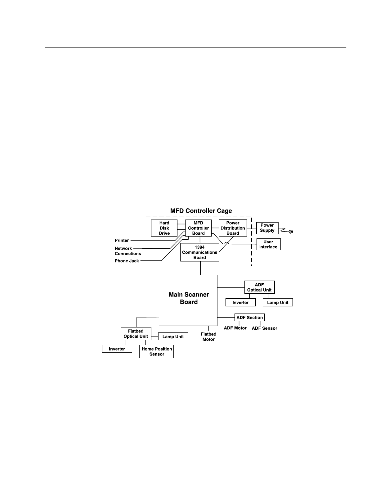
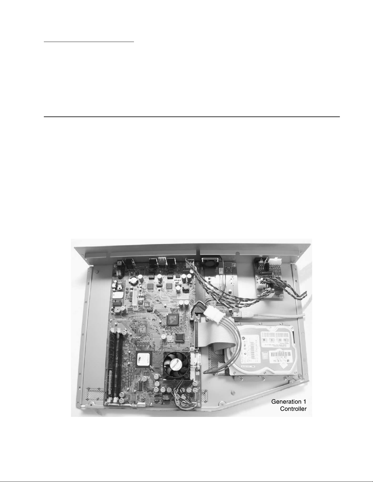
System Description
The Lexmark X4500 is a duplexing scanner option which can synchronously scan both
the top and bottom sides of a document in color. The major system components include a
main scanner control board, an automatic document feeder, flatbed, two optical CCD
modules (one in ADF, one in flatbed), a user interface with a touch screen panel and a
multifunction device controller cage located within the base of the scanner. The MFD
controller cage includes a 1394 communications card to communicate with the main
scanner board (for generation 1 controller cards only; for generation 2 controller cards,
the 1394 communications circuitry is built into the controller card), a MFD controller board
to process all jobs performed on the X4500, a hard disk drive containing the operational
code for the system and providing memory for processing jobs, and a power distribution
board. An external power supply provides 5, 12, and 24 V dc to the entire scanner
system.
The following figure shows the system block diagram.
4036-304
Mechanical Operation
Flatbed Operation
When scanning, place the document on the flatbed glass platen, the flatbed optical unit/
carrier moves across the underside of the glass, and scans the document. A chargecoupled device (CCD) mounts to the carrier and optically reads the image from the page.
The carrier is driven by a 2-phase stepping motor which moves the carriage at 1/300 inch
each step.
Overview 1-5
Page 14

4036-304
Auto Document Feeder Operation
When using the Auto Document Feeder (ADF) mechanism, a page is fed into the ADF by
a pick roller and through the ADF by a feed roller. A separation pad located opposite to
the pick roller is used to properly feed the pages one at a time when placed on the input
tray. The flatbed optical unit/carrier is positioned to the far left so when the paper passes
through the ADF, the bottom side of the page is scanned by the flatbed CCD. The home
position sensor detects when the carrier is in the proper position for ADF scanning. In
addition, an ADF cover open sensor detects when the upper ADF assembly is open or
closed into proper operating position. The scanner cannot operate when this sensor is
open.
While the page is fed through and scanned from the bottom via the flatbed CCD, the top
side of the page is simultaneously scanned via a CCD unit positioned within the ADF unit.
As the page feeds between the two CCD units, the page discharges to the exit tray on the
left side of the ADF.
1-6 Service Manual
Page 15
4036-304
Scanner Mechanism Overview and Locations
This section contains an overview of the major components of the scanner hardware.
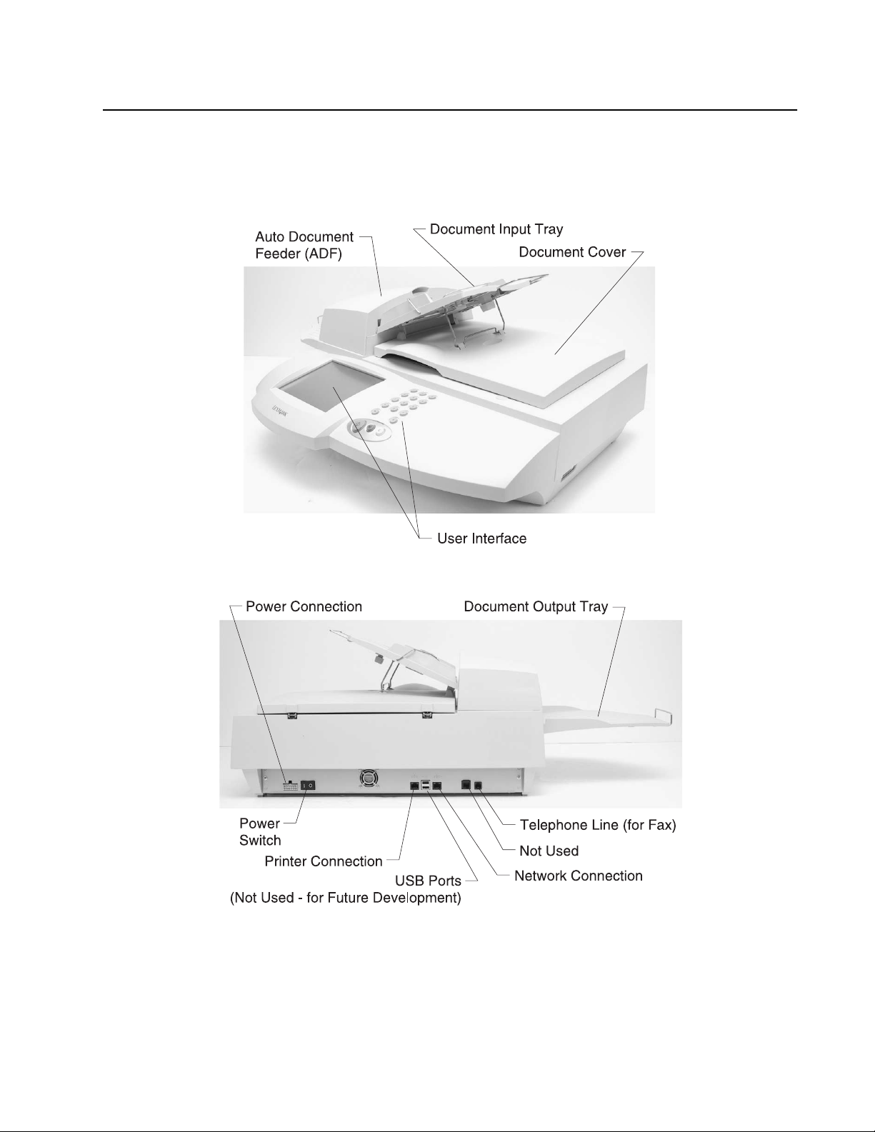
External View
Overview 1-7
Page 16
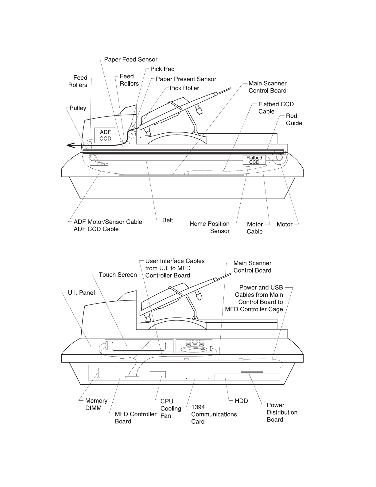
Internal Components
4036-304
1-8 Service Manual
Page 17

Abbreviations
4036-304
ADF Auto Document Feeder
CCD Charge-Couple Device
CCFL Cold Cathode Fluorescent Lamp
CDB Command Descriptor Blocks
DMM Digital Multimeter
LED Light Emitting Diode
MFD Multi Function Device
PCBA Printed Circuit Board Assembly
UI User Inte r face
Overview 1-9
Page 18

4036-304
1-10 Service Manual
Page 19
2. Problem Solving
This chapter describes two methods to solve the operational problems. The first relies on
the scanner internal diagnostics to report error codes. The second uses troubleshooting
techniques to isolate the problem. In many cases, the internal error codes will help you to
locate the source of the problem quickly. If no error codes are reported, or if the error
codes do not locate the source of the problem, refer to the troubleshooting section.
Error Codes
MFD Controller Errors
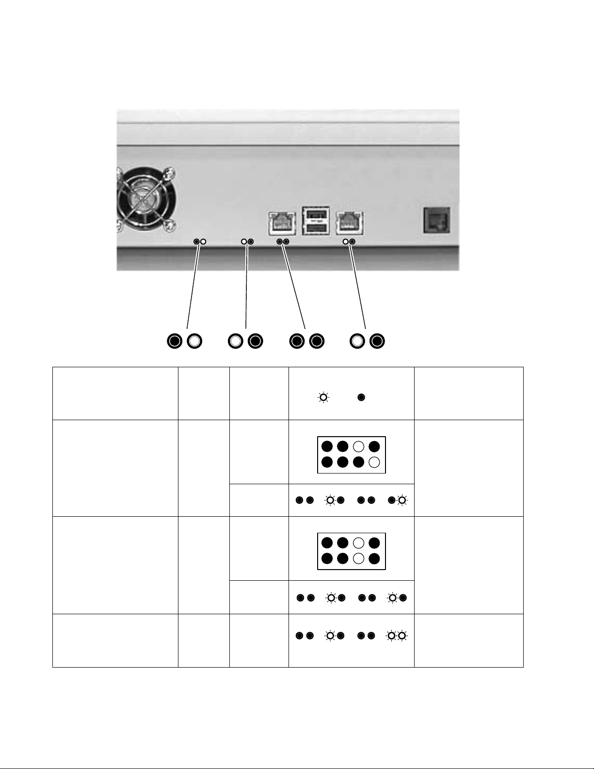
MFD Controller Errors are errors detected by the MFD controller card within the MFD
cage pertaining to electronic cards. All MFD controller cage errors are posted to the user
interface touch screen along with audible beep codes and LED codes. During the PowerOn Self T est procedure, errors detected cause a number of audible beeps to be produced
three times. The corresponding LED pattern continuously displays on the controller card
until the system is powered down. Use the following tables to read the beep/LED codes
and follow the recommended repair action.
4036-304
Note: For gen erat ion 1 MFD controller cards , th ere ar e two r ow s of f our LEDs . The LED s
are difficult to view as the controller cage must be removed from the scanner. The LED
pattern shown depicts which LEDs are illuminated in the two rows.
Problem Solving 2-1
Page 20
4036-304
Note: For generation 2 MFD controller cards, there are four pairs of LEDs. The LEDs are
viewable after the controller cage is removed from the scanner. The LED pattern shown
depicts which LEDs are illuminated in the two rows.
MFD
Error number and
description
Error: 21 - Modem not found 2 1st Modem on the MFD
Error: 22 - PCI Bus failure 2 1st Replace the MFD
Error: 23 - Internal scanner
card failure
Number
of beeps
controller
card
generation
2nd
2nd
2 The 1394
LED pattern
(on= , off= )
Action
controller card is not
found. Replace the
MFD controller card.
controller card.
communicatio n protocol
on the MFD controller
card has fai led. Replace
the MFD controller card.
2-2 Service Manual
Page 21
Error number and
description
Number
of beeps
4036-304
MFD
controller
card
generation
LED pattern
(on= , off= )
Action
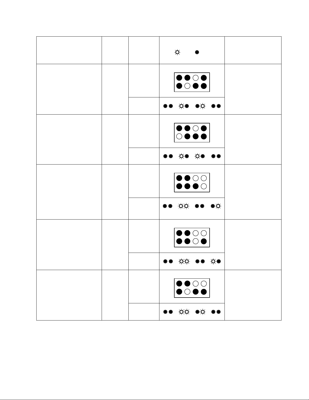
Error: 24 - Serial port failure 2 1st Problem with TTY/Serial
2nd
Error: 28 - Problem with the
CPU
Error: 31 - No hard drive
2 1st Replace the MFD
2nd
3 1st Check connections to
found.
Note: Error message not
displayed. Only beep code
and LED patterns are
generated for error 31.
2nd
Port. Replace the MFD
controller card.
controller card.
the hard disk drive and
associated cables for
continuity. Check power
going to the hard disk
drive. Replace the
power distribution card
if no power is p resent. If
power is present,
replace the hard disk
drive.
Error: 32 - Corrupt hard
disk drive
Note: Error message not
displayed. Only beep code
and LED patterns are
generated for error 32.
Error: 34 - Hard Drive failure 3 1st There was an error
3 1st Replace or ref ormat the
hard disk drive. See
“Hard disk drive
refresh” on page 3-1.
2nd
writing to the hard disk
drive. Replace or
reformat the hard disk
drive. See “Hard disk
drive refresh” on
page 3-1.
2nd
Problem Solving 2-3
Page 22

Error number and
description
Number
of beeps
MFD
controller
card
generation
4036-304
LED pattern
(on= , off= )
Action
Error: 41 - Scanner interface
not found
Error: 51 - Not enough
memory
Note: Error message not
displayed. Only beep code
and LED patterns are
generated for error 51.
Error: 52 - Not enough
memory
4 1st The scanner image
2nd
5 1st The memory DIMM w as
2nd
5 1st The memory DIMM w as
2nd
N/A
processor board was
not found. Check
connections to the
interface board. If
connections are good,
replace the image
processor board.
not detected or not
functioning. Replace the
memory DIMM.
found, but not enough
memory is present.
Replace the memory
DIMM.
Error: 71 - User Interface
failure
7 1st A problem was detected
2nd
with the user interface.
Check the connection of
all cables connecting
the UI to the MFD
controller card. If cab les
are okay, replace the
user interface. If
problem persists,
replace the MFD
controller card.
2-4 Service Manual
Page 23

4036-304
Scanner Errors
Scanner Errors are errors detected within the scanner mechanism and auto document
feeder assembly. These errors appear on the user interface touch screen along with a
number of flashes of the flatbed CCD lamp (the flash sequence is repeated 10 times).
See the following table for an explanation of each error code and the corrective action to
resolve the problem.
Number of CCD
Lamp Flashes
1 Oasis 1 SDRAM failure Replace the main scanner
2 Oasis 2 SDRAM failure Replace the main scanner
3 CPU SDRAM failure Replace the main scanner
4 Flatbed A/D Dark Calibration
5 ADF A/D Dark Calibration
6 Home Sensor failure Check the flatbed motor, belt
Error Message Display ed
to UI
Error
Error
Action
board.
board.
board.
Replace the flatbed optical
unit assembly. If problem
persists, replace th e main
scanner board.
Replace the ADF optical unit.
If problem persists, replace the
main scanner board.
and home position sensor for
proper operation. Replace any
defective parts. If no defective
parts are found, replace the
main scanner board.
7 Flatbed Lamp failure Check the flatbed optical unit
for proper connection.
Replace the flatbed optical
unit if necessary.
8 ADF Lamp failure Check the ADF optical unit for
proper connection. Replace
the ADF optical unit if
necessary.
None SCSI Command Not
Supported
None Invalid field in CDB Replace the main scanner
Replace the main scanner
board.
board.
Problem Solving 2-5
Page 24

4036-304
Number of CCD
Lamp Flashes
None Could not match scanner,
Error Message Display ed
to UI
aborting
Action
The MFD controller cage
could not find the rest of the
scanner. Make sure the USBstyle cable is properly
connected between the 1394
communications board and
main scanner control board.
If problem persists, replace the
main scanner board. If
problem persists, replace
1394 communications board.
2-6 Service Manual
Page 25

Troubleshooting
The tables in this section provide detailed troubleshooting information.
The Power does not come on
4036-304
Cause
Unplugged
from outlet
AC power
unplugged at
power supply
Power switch
is OFF
Power supply
power
distribution
board
connection
failure
Power supply
output voltage
failure
Power
distribution
board
Relevant
Unit
None Visual check Insert the ac
LVPS Visual check Insert the ac
None Visual check Turn the power
None Visual check Connect the
LVPS Tester check
Power
distribution
board
Check * Action
plug into the
outlet.
cable into
power supply.
switch on.
connector.
Replace the
the LVPS
(+5V +12V,
+24V, GND)
Tester check
(+5V, GND)
power supply.
Replace the
failed power
distribution
board.
MFD
controller
board
* Check explains how to check the failed item.To do a visual check observe the part or
observe the offline test display on the front panel. T o do a tester check, check the voltage
levels of the relevant units. (See Connector Locations.)
MFD
controller
board
None If problem still
exists, replace
MFD controller
board.
Problem Solving 2-7
Page 26

4036-304
Scan module does not move to lock position
Cause
Home
position
sensor board
failure
Motor-main
control PCBA
connection
failure
Motor failure Carrier motor Visual check Replace the
Power supplymain control
board
connection
failure
Power supply
fails.
Relevant
Unit
CCD board Tester check Replace the
None Visual check Connect the
None Visual check Connect the
Power supply Tester check
Check Action
CCD PCBA.
connector.
carrier motor.
connector.
Replace the
(+24V, GND)
power supply.
2-8 Service Manual
Page 27

4036-304
Scan module does not move to the home position
Cause
Home
position
sensor boardmain control
PCBA
connection
failure
Home
position
sensor board
failure
Power supplymain control
board
connection
failure
Power supply
fails
Lamp failure Lamp Visual check Replace the
Relevant
Unit
None Visual check Connect the
Sensor in the
flatbed CCD
assembly
None Visual check Connect the
Power supply Tester check
Check Action
connector.
Tester check Replace the
flatbed CCD
optical unit.
connector.
Replace the
(+5V, +24V,
GND)
power supply.
flatbed CCD
optical unit.
Inverter
failure
CCD boardmain scanner
board
connection
failure
CCD board
fails
Inverter Visual check Replace the
flatbed CCD
optical unit.
None Visual check Connect the
connector.
CCD board Tester check Replace the
flatbed CCD
optical unit.
Problem Solving 2-9
Page 28

4036-304
Scan module does not move to the flatbed position
Cause
Power supplymain scanner
board
connection
failure
Power supply
fails
Motor-main
scanner
board
connection
failure
Motor failure Carrier motor Visual check Replace the
Belt broken or
loose
Relevant
Unit
None Visual check Connect the
Power supply Tester check
None Visual check Connect the
Carrier belt Visual check Reposition belt
Check Action
connector.
Replace the
(+5V, +24V,
GND)
power supply.
connector.
carrier motor.
or replace if
defective.
Reading is not performed
Cause
ADF cover
open
Relevant
Unit
ADF cover Visual check Close the ADF
Check Action
cover.
2-10 Service Manual
Page 29

4036-304
Image does not appear
Cause
ADF cover
open
1394
Communication boardmain control
board
connection
failure
Lamp Inv erter
failure
CCD boardmain scanner
board
connection
failure
CCD board
fails
Relevant
Unit
ADF cover Visual check Close the ADF
None Visual check Connect the
Lamp inverter Visual check Replace the
None Visual check Connect the
CCD board Visual check Replace the
Check Action
cover.
connector.
CCD optical
unit.
connector.
optical unit.
Large jitter
Cause
1394
Communication - main
control board
connection
failure
Motor-main
scanner
PCBA
connection
failure
Motor failure Carrier motor Visual check Replace the
Relevant
Unit
None Visual check Connect the
None Visual check Connect the
Check Action
connector.
connector.
carrier motor.
Problem Solving 2-11
Page 30

4036-304
Reading position deviation
Cause
Motor-main
scanner
PCBA
connection
failure
Motor failure Carrier motor Visual check Replace the
Home
position
sensor boardmain scanner
PCBA cable
failure
Home
position
sensor board
failure
Relevant
Unit
None Visual check Connect the
Flatbed CCD
optical unit
cable
Flatbed CCD
optical unit
Check Action
connector.
carrier motor.
Tester or
visual check
Tester check Replace the
Replace the
flatbed CCD
optical unit
cable.
flatbed CCD
optical unit.
2-12 Service Manual
Page 31

Image unclea r
4036-304
Cause
Lamp too
dark
Dirt on
calibration
reference
plate
Dirt on the
mirrors
Dirt on the
lens
Relevant
Unit
Lamp Visual check Replace CCD
Calibration
reference
plate
Mirrors Visual check Clean the
Lens Visual check Clean the lens
Check Action
optical unit.
Visual check Clean the
flatbed glass
with isopropyl
alcohol.
mirrors with
isopropyl
alcohol.
with isopropyl
alcohol.
Problem Solving 2-13
Page 32

4036-304
Strange Sound Generated (flatbed)
Cause
Motor unit
failure
Main scanner
card failure
Scanning
module
Dirt on rail None Visual check Clean the rail
Relevant
Unit
Motor unit Visual check Replace the
Main scanner
card
Scanning
module
Check Action
carrier motor.
Replace the
main scanner
card.
Check if
scanning
module is
loose.
Replace the
main scanner
card.
Replace the
flatbed CCD
optical unit.
with isopropyl
alcohol.
Frequent paper jam, double feed or skew
Cause
Paper setting
failure
Relevant
Unit
Operation
error
Check Action
Is the paper
correctly set
in the paper
chute?
Teach users to
properly
position the
paper.
Paper failure Op eration
error
ADF
connector
slip-off
Pad assembly
failure
ADF unit
failure
ADF unit Visual check
Pad assembly Check the
ADF unit Replace the
Is the
specified
paper used?
of motor
rotation
pad assembly
for wear and
tear.
ADF unit.
None
Connect the
connector.
Clean/replace
the pad
assembly/touch
spring unit
Replace the
ADF unit.
2-14 Service Manual
Page 33

4036-304
Strange sound generated (ADF)
Cause
Paper setting
failure
Paper failure Operation
ADF
connector
slip-off
ADF unit
failure
Relevant
Unit
Operation
error
error
ADF unit Visual check
ADF unit Replace the
Check Action
Is the paper
correctly set
in the paper
chute?
Is the
specified
paper used?
of motor
rotation
ADF unit.
Teach users to
properly
position the
paper.
None
Connect the
connector.
Replace the
ADF unit.
Problem Solving 2-15
Page 34

4036-304
2-16 Service Manual
Page 35

3. Maintenance
This chapter describes cleaning methods maintenance parts replacement, and
adjustment and lubrication necessary for normal scanner operation.
Perform preventative maintenance in the shorter term either every six months or every
60,000 sheets scanning.
Cleaning
Cover and Glass
With soft cloth, wipe the cover and glass. If the dirt is heavy, use a neutral cleanser or
alcohol. Wipe the glass carefully so no cleanser remains on the surface.
Touch Screen
Wipe the touch screen with a clean, lint-free cotton cloth dampened with water.
4036-304
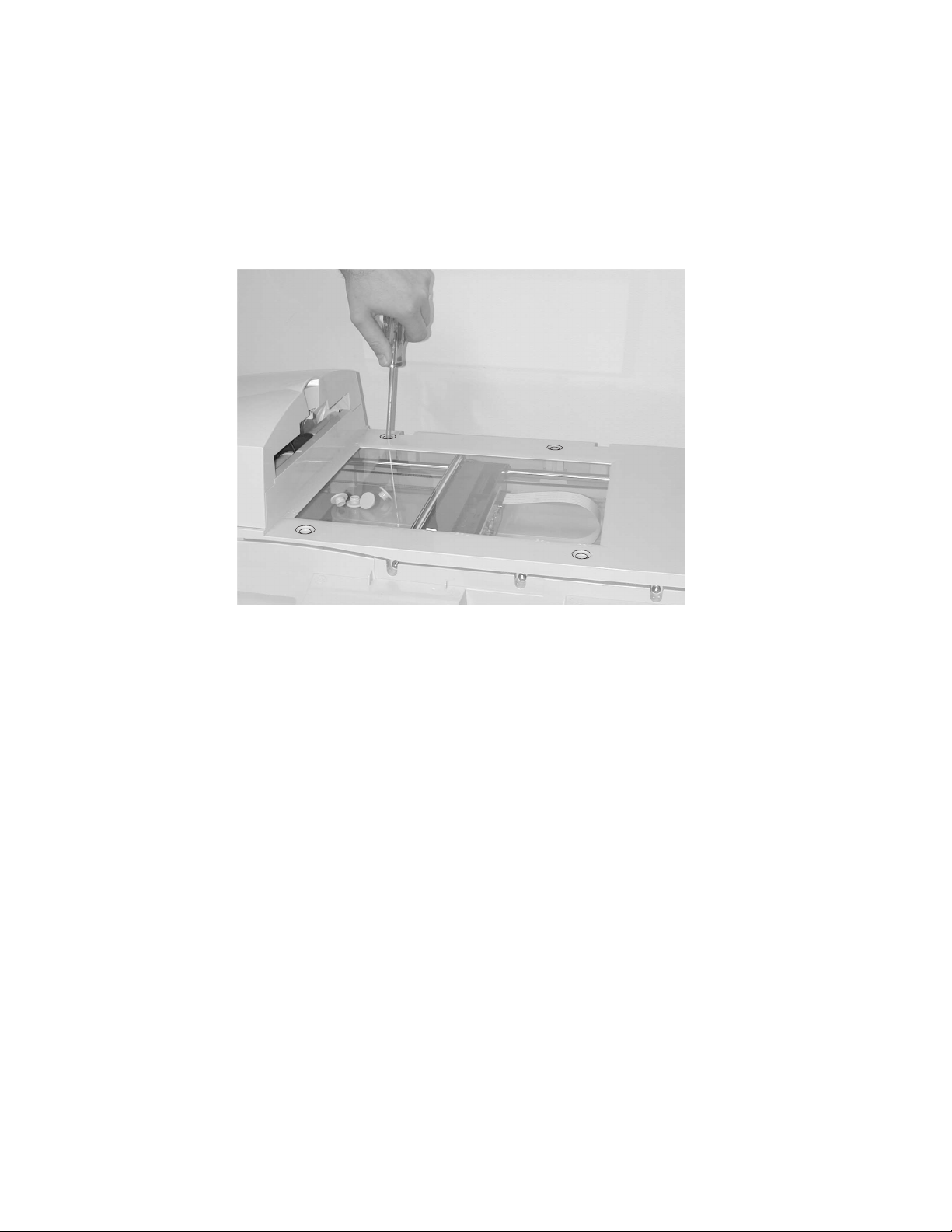
ADF Unit
Push the ADF unit backward to open the unit. Clean the pad assembly and feed roller in
the ADF with a lint-free cloth and isopropyl alcohol. Clean the pad assembly by wiping it
in the direction of the arrow as shown.
Maintenance 3-1
Page 36

Maintenance Tools
The following table describes the tools necessary for the maintenance of this scanner.
Name Description
Flathead screwdriver Idler pulley module screw
Phillips screwdriver (magnetic) Nominal No.2 M3, M4
Nut driver 6 mm
Digital voltmeter With 0.01 V range
Chip Puller Puller for main scanner board chip
4036-304
Removals
Parts Replacement
1. Clean the disassembly and assembly location.
2. Turn off the power switch and remove the AC plug from the outlet before
disassembly and assembly.
3. Follow the disassembly and assembly procedures. Never loosen the screws of parts
that must not be disassembled. These scre ws have a red coating.
4. Store the disassembled parts in a clean place to avoid loss.
5. After replacement, check the contacts and spare part mounting.
6. Assemble in the reverse order of disassembly.
3-2 Service Manual
Page 37

4036-304
CCD Board Screws
Screws for the CCD board in the optical unit are as shown. These screws have a red
coating indicating they should never be loosened.
Flatbed CCD Optical Unit
ADF CCD Optical Unit
Maintenance 3-3
Page 38

4036-304
ADF Snap-in Pad Module Removal and Mounting
After scanning approximately 100,000 pages through the ADF, the ADF pad module may
be worn and you may experience problems with document feeding. In this case, replace
the ADF pad module.
To remove the ADF snap-in pad module:
1. Push the ADF unit backward.
2. Gently pull out the snap-in pad module.
To mount the ADF snap-in module,
1. Hold both arms of the snap-in pad module.
2. Gently place the module into the pad holder.
Note: Inspect the feed roller and clean as necessary.
3-4 Service Manual
Page 39

4036-304
Document Cover Remo val
Lift the document cover to remove the studs from the hinge holes. The studs are loosely
attached to the hinge holes to accommodate the depth of the original.
ADF Cover Removal
Remove the two ADF cover screws and lift the ADF cover.
Maintenance 3-5
Page 40

4036-304
ADF Optical CCD Unit Removal
Warning: Do not loosen any screws with red coating.
1. Remove the ADF cover. Go to “ADF Cover Removal” on page 3-5. Remove the
two screws from the ADF optical CCD unit as shown, and pull out the unit.
2. Use a flat screwdriver to raise the latch and remove the inverter board.
3. Disconnect the lamp connector from the inverter board.
3-6 Service Manual
Page 41

4036-304
4. Disconnect the two CCD connectors.
5. Remove the ADF optical CCD unit.
ADF Unit (Upper and Lower Unit) Removal
1. Remove the ADF optical CCD unit. Go to “ADF Optical CCD Unit Removal” on
page 3-6.
2. Remove the screws located at the four corners of the ADF unit.
Maintenance 3-7
Page 42

4036-304
3. Disconnect 15PIN ADF motor/sensor cable from ADF motor/sensor card.
4. Lift the ADF unit and remove it.
3-8 Service Manual
Page 43

4036-304
Note: The upper and lower units of the ADF unit can now be separated.
User Interface Removal
1. Remove the document output tray and document cover.
2. Place the scanner on its back.
3. Remove the three screws to loosen the user interface from the scanner.
Maintenance 3-9
Page 44

4036-304
4. Place the scanner right side up and slide the user interface forward.
5. Disconnect the cables.
3-10 Service Manual
Page 45

4036-304
6. Remove the right side touch screen support bracket to disconnect the ground wire.
7. Remove the user interface gently.
Maintenance 3-11
Page 46
4036-304
Upper Housing Removal
1. Remove the ADF unit. Go to “ADF Unit (Upper and Lower Unit) Removal” on
page 3-7.
2. Remove the user interface. Go to “User Interface Removal” on page 3-9.
3. Remove the four rubber pads with a flat screwdriver.
4. Remove the screws beneath the rubber pads.
3-12 Service Manual
Page 47

4036-304
5. Remove the four screws on the left side of the housing.
6. Remove the five screws form the front of the housing.
7. Remove the upper housing.
Maintenance 3-13
Page 48

4036-304
Flatbed CCD Optical Unit Removal
Warning: Do not loosen any screws with red coating.
1. Remove the upper housing. Go to “Upper Housing Removal” on page 3-12.
2. Press the pulley on the carriage belt pulley assembly toward the center of the unit
and remove the carriage belt from the pulley.
3-14 Service Manual
Page 49

4036-304
3. Remove the sliding rod and the flat cable. (See following figures.) Warning: Be very
careful when handling the flatbed optical CCD. The lamp is exposed and can be
easily broken. Do not touch.
4. Take out the flatbed optical CCD.
5. Disconnect the belt from the side of the flatbed optical CCD.
Maintenance 3-15
Page 50

4036-304
Carriage Motor Assembly Removal
1. Remove the upper housing unit. Go to “Upper Housing Removal” on page 3-12.
2. Press the pulley on the carriage belt pulley assembly toward the center of the unit
and remove the carriage belt from the pulley.
3. Disconnect connector from carriage motor assembly.
4. Remove the three screws from carriage motor assembly.
5. Remove the carriage motor.
Carriage Belt Pulley Assembly Removal
1. Remove the upper housing unit.
2. Press the pulley on the carriage belt pulley assembly toward the center of the unit
and remove the carriage belt from the pulley.
3. Remove the two screws.
4. Remove the carriage belt pulley assembly.
MFD Controller Cage Removal
1. Remove the document output tray and document cover.
2. Place the scanner on its back.
3. Remove eight screws from the bottom housing.
3-16 Service Manual
Page 51

4036-304
4. Lower MFD controller cage and disconnect the three connectors and ground wire.
Maintenance 3-17
Page 52

4036-304
5. Swing the MFD controller cage assembly to the right and disconnect the two cables.
Use a screwdriver on the lower cable connector to unlatch the connector.
3-18 Service Manual
6. Remove the MFD controller cage.
Note: When reinstalling the USB-style cable to the main control board, connect the cable
to the upper connector.
Page 53

4036-304
Hard Disk Drive, MFD Controller Card, 1394
Communications Card and Power Distribution Board
Removal
1. Remove the MFD controller cage. Go to “MFD Controller Cage Removal” on
page 3-16.
2. With the MFD controller cage positioned upside down near an edge of a table,
remove the two screws from the back side and three screws from the bottom.
3. Turn the MFD controller cage right side up and lift the upper shield from the cage.
Maintenance 3-19
Page 54

4036-304
4. Remove the component you want from within the MFD cage.
3-20 Service Manual
Page 55

4036-304
Main Control Board Removal
1. Remove the MFD controller cage. Go to “MFD Controller Cage Removal” on
page 3-16.
2. Remove the screws securing the main control board.
3. Disconnect the cables and remove the board.
Maintenance 3-21
Page 56

4036-304
3-22 Service Manual
Note: When replacing the main scanner control board with a new one, remove the
EPROM from the old board (with a chip puller) and install it in the new board. This
EPROM contains settings unique to the scanner.
Page 57

4. Connector Locations
The pin assignments shown are voltages and grounds which can be tested in the field.
Use a multimeter grounded to the scanner MFD controller cage when measuring the
voltage for the main scanner board.
Main Scanner Board
ADF Video Circuit J7:
Pin No. Assignment
1Ground
3Ground
5Ground
4036-304
ADF Video Circuit J8:
Pin No. Assignment
1Ground
2+24V dc
3Ground
4Ground
5Ground
9 +5V dc
12 Ground
13 Ground
14 +24V dc
Flatbed Video Circuit J9:
Pin No. Assignment
14 +24V dc
15 Analog Ground
Connector Locations 4-1
Page 58

4036-304
MFD Controller Cage
All components within the MFD controller cage are self diagnosed. Any errors are
reported as MFD controller cage errors.
Low Voltage Power Supply
The following diagram and chart represents the power supply output connector.
Pin No. Wire Color Assignment
1 Black Ground
2 Black Ground
3 Black Ground
4 Black Ground
5 Black Ground
6 Black Ground
7 W hi te +24V dc
8Red +5V dc
9 Yellow +12V dc
10 Red +5V dc
11 Red +5V dc
12 Red +5V dc
4-2 Service Manual
Page 59

5. Parts Catalog
4036-304
Parts Catalog 5-1
Page 60

Assembly 1: Upper Scanner
13
4036-304
10
12
11
8
9
7
6
5
4
1
2
3
5-2 Service Manual
Page 61

Assembly 1: Upper Scanner
4036-304
AsmIndex
Part
Number
Units Description
1 56P2717 1 Tray, Document Input
2 56P0024 1 Cover, Scanner Document
3 56P0032 1 Cover, Upper with Glass
4 56P0020 1 User Interface, Complete
5 56P0030 1 Assembly, Lower ADF
6 56P0023 1 Tray, Document Output
7 56P0025 1 Assembly, ADF Optical Unit
8 56P0029 1 Assembly, Upper ADF
9 56P0079 1 Pad, Pick Roller
10 56P0028 1 Sensor, Paper Feed
11 56P0027 1 Sensor, Paper Present
12 56P0026 1 Board, ADF Motor/Sensor
13 56P2401 1 Cover, ADF Upper
Parts Catalog 5-3
Page 62

Assembly 2: Lower Scanner
4036-304
5
3
2
1
6
4
8
7
10
9
11
21
22 23
5-4 Service Manual
20
19
24
18
17
16
15
12
13
14
Page 63

Assembly 2: Lower Scanner
4036-304
AsmIndex
Part
Number
Units Description
1 56P0036 1 Cable, ADF CCD (6PIN + 14PIN)
2 56P0035 1 Cable, ADF Motor/Sensor (15PIN)
3 56P0033 1 Pulley Assembly, Carriage Belt
4 56P0031 1 Assembly, Flatbed CCD Optical Unit
5 56P1466 1 Lamp, Flatbed CCD
6 56P0308 1 Card Assembly, Flatbed CCD Lamp Invertor
7 56P0037 1 Belt, Carriage
8 56P0042 1 Cable, Flatbed Optical Unit
9 56P0034 1 Motor Assembly, Carriage
10 56P0021 1 Board, Main Scanner Control
11 12G6918 1 Power Supply, Universal, External
12 56P1473 1 Cable, 1394 Communications (generation 2)
13 11D0328 1 Line Cord, US, Canada, APG (LV), LAD (LV)
13 11D0329 1 Line Cord, Peru
13 11D0330 1 Line Cord, Argentina
13 11D0331 1 Line Cord, Brazil
13 11D0332 1 Line Cord, Chile
13 11D0333 1 Line Cord, Denmark
13 11D0334 1 Line Cord, France, Germany, Spain, Belgium, England, Europe
13 11D0335 1 Line Cord, Italy
13 11D0336 1 Switzerland
13 11D0337 1 Line Cord, UK, Ireland, Egypt
13 11D0338 1 Line Cord, Israel
13 11D0339 1 Line Cord, South Africa
13 99A0471 1 Line Cord, PRC
14 56P0192 1 Board, Power Distribution
15 56P0022 1 Board, 1394 Communications (used only with generation 1 controller board)
16 56P2467 1 Drive Assembly, Hard Disk
17 56P1472 1 Cable, HDD to Controller - 80 Conductor
18 56P2554 1 Board, Controller, WW non-Australia/New Zealand (generation 2)
18 56P2555 1 Board, Controller, Australia/New Zealand (generation 2)
Parts Catalog 5-5
Page 64

Assembly 2 (cont.): Lower Scanner
4036-304
5
3
2
1
6
4
8
7
10
9
11
20
2 23
5-6 Service Manual
19
24
18
17
16
15
12
13
14
Page 65

4036-304
Assembly 2 (cont.): Lower Scanner
AsmIndex
19 12G9063 1 Fan, CPU Cooling (used only with generation 1 controller board)
19 56P2406 1 Fan, CPU Cooling (used only with generation 2 controller board)
20 56P9910 1 Card Assembly, 128MB DIMM
21 56P2112 1 Cable, 15 pin User Interface
22 56P2110 1 Cable, 14 pin User Interface
23 56P2042 1 Cable, 7 pin User Interface
24 56P1808 1 Fan, Controller Cage Cooling
NS 56P0558 1 Cable, RJ11 with Torriod
NS 56P0559 1 Cable, RJ45 with Torriod
NS 56P1211 1 Adapter, UK phone
Part
Number
Units Description
Note:
• Refer to LED pattern images on page “MFD Controller Errors” on page 2-1 to identify
controller board generation.
• If replacing a generation 1 MFD controller board with a generation 2 board, the following must
be performed. The 1394 communications board and generation 1 1394 communications cable
should be removed and discarded. In place of the discarded parts, a generation 2 1394
communications cable should be installed to connect the generation 2 MFD controller board to
the main scanner control board. Included with the generation 2 1394 communications cable is
an insulator which must be installed on a metal standoff on the controller cage. Instructions for
installation are included with the generation 2 communications cable FRU.
Parts Catalog 5-7
Page 66

4036-304
5-8 Service Manual
Page 67

Index
4036-304
A
Abbreviations 1-9
C
Cleaning
ADF Unit
Cover and Glass
Touch Screen
Connector Locations
3-1
3-1
3-1
4-1
E
Error Codes
MFD Controller
Scanner
2-1
2-5
M
Maintenance 3-1
Maintenance Tools
3-2
O
Overview 1-1
P
Parts Catalog 5-1
Parts Replacement
Problem Solving
Product Description
Product Features
Product Specifications
3-2
2-1
1-1
1-1
1-3
R
Removals
ADF Cover
ADF Optical CCD Unit
ADF Snap-in Pad Module
ADF Unit
Carriage Belt Pulley Assembly
Carriage Motor Assembly
Communications Card, 1394
Document Cover
Flatbed CCD Optical Unit
Hard Disk Drive
Main Control Board
MFD Controller Cage
MFD Controller Card
Power Distribution Board
Upper Housing
User Interface
3-5
3-7
3-5
3-19
3-21
3-12
3-9
3-6
3-16
3-19
3-4
3-16
3-14
3-19
3-16
3-19
S
Safety Information v-v
T
Theory of Operation
Mechanical Operation
System Description
Troubleshooting
2-7
U
Unit 3-1
Part Numbers
11D0328 5-5
11D0329
11D0330
11D0331
11D0332
11D0333
11D0334
11D0335
11D0336
11D0337
11D0338
11D0339
12G6918
12G9063
56P0020
56P0021
56P0022
56P0023
56P0024
56P0025
56P0026
56P0027
56P0028
56P0029
56P0030
56P0031
56P0032
56P0033
56P0034
56P0035
56P0036
56P0037
56P0042
56P0079
56P0192
56P0308
5-5
5-5
5-5
5-5
5-5
5-5
5-5
5-5
5-5
5-5
5-5
5-5
5-7
5-3
5-5
5-5
5-3
5-3
5-3
5-3
5-3
5-3
5-3
5-3
5-5
5-3
5-5
5-5
5-5
5-5
5-5
5-5
5-3
5-5
5-5
1-5
1-5
I-1
Page 68

4036-304
56P0558
56P0559
56P1211
56P1466
56P1472
56P1473
56P1808
56P2042
56P2110
56P2112
56P2401
56P2406
56P2467
56P2554
56P2555
56P2717
56P9910
99A0471
5-7
5-7
5-7
5-5
5-5
5-5
5-7
5-7
5-7
5-7
5-3
5-7
5-5
5-5
5-5
5-3
5-7
5-5
I-2 Service Manual
 Loading...