

Page 1

Lexmark Optra TM W810
Laser Printer
• Table of Contents
•Start Diagnostics
• Safety and Notices
4023-001
• Trademarks
•Index
• Manuals Menu
Lexmark and Lexmark with diamond
design are trade ma rks of Lexmark
International, Inc., registered in the
United States and/or ot her countries.
Page 2

4023-001
Edition: March 24, 2006
The following paragraph does not apply to any country where such provisions are
inconsistent with local law: LEXMARK INTERN ATIONAL, INC. PROVIDES THIS
PUBLICATION “AS IS” WITHOUT WARRANTY OF ANY KIND, EITHER EXPRESS OR
IMPLIED, INCLUDING , BUT NOT LIMITED TO, THE IMPLIED W A RRANTIES OF
MERCHANTABILITY OR FITNESS FOR A PARTICULAR PURPOSE. Some states do
not all o w di sc la im er o f e xp res s o r im plie d w ar r ant i es in ce rta in t r ansa ct io ns , t he refore, t hi s
statement may not apply to you.
This publication could include technical inaccuracies or typographical errors. Changes are
periodically made to the information herein; these changes will be incorporated in later
editions. Improvements or changes in the products or the programs described may be
made at any time.
A form for reader’s comments is provided at the back of this publication. If the form has
been removed, comments may be addressed t o Lexmark International, Inc., Department
D22/032-2, 740 West New Circle Road, Lexington, Kentucky 4055 0, U.S.A. Lexmark may
use or distribute any of the information you supply in any way it believes appropriate
without incurring any obligation to you.
Lexmark, MarkNet, MarkVision, Optra and OptraImage are trademarks of Lexmark
International, Inc., registered in the United Sta tes and/or other co untries .
Other tradema rks are the property of their respective owner s.
© Copyright Lexmark International, Inc. 1999, 2004
All rights reserved.
UNITED STATES GOVERNMENT RESTRICTED RIGHTS
This software and documentation are provided with RESTRICTED RIGHTS. Use,
duplication or disclosure by the Government is subject to restrictions as set forth in
subparagraph (c)(1)(ii) of the Right s in Technical Data and Computer Software clause at
DFARS 25 2.227-7013 and in applicable FAR provisions: Le x mark International, Inc.,
Lexington, KY 40550.
U.S.A. P/N: 12G3978
Page 3

4023-001
Table of Contents
Notices and Safety Information. . . . . . . . . . . . . . . . . . . . . . . . . . . xiii
General Information . . . . . . . . . . . . . . . . . . . . . . . . . . . . . . . . . . . . . .1
Maintenance Approach . . . . . . . . . . . . . . . . . . . . . . . . . . . . . . . . . . . .1
Tools . . . . . . . . . . . . . . . . . . . . . . . . . . . . . . . . . . . . . . . . . . . . . . . . . . .1
Serial Number . . . . . . . . . . . . . . . . . . . . . . . . . . . . . . . . . . . . . . . . . . .2
Abbreviations . . . . . . . . . . . . . . . . . . . . . . . . . . . . . . . . . . . . . . . . . . . .3
Standard Features . . . . . . . . . . . . . . . . . . . . . . . . . . . . . . . . . . . . . . . .4
Printer (Main) . . . . . . . . . . . . . . . . . . . . . . . . . . . . . . . . . . . . . . . . . .4
Options. . . . . . . . . . . . . . . . . . . . . . . . . . . . . . . . . . . . . . . . . . . . . . . 6
Printer/Options . . . . . . . . . . . . . . . . . . . . . . . . . . . . . . . . . . . . . . . . . . .7
Parts Identification . . . . . . . . . . . . . . . . . . . . . . . . . . . . . . . . . . . . . .7
Printer Configuration . . . . . . . . . . . . . . . . . . . . . . . . . . . . . . . . . . . . . .8
General Description of Each Section . . . . . . . . . . . . . . . . . . . . . . . . . .9
Paper Feed Section . . . . . . . . . . . . . . . . . . . . . . . . . . . . . . . . . . . . .9
Printhead Unit (Exposure Section). . . . . . . . . . . . . . . . . . . . . . . . . .9
Imaging Cartridge (Charging, Development Section) . . . . . . . . . . .9
Image Transfer Section (Release Section) . . . . . . . . . . . . . . . . . . .9
Fusing Section. . . . . . . . . . . . . . . . . . . . . . . . . . . . . . . . . . . . . . . . .9
Cleaning Section . . . . . . . . . . . . . . . . . . . . . . . . . . . . . . . . . . . . . . .9
Paper Exit Section . . . . . . . . . . . . . . . . . . . . . . . . . . . . . . . . . . . . .10
General Flow for Printing Process . . . . . . . . . . . . . . . . . . . . . . . . . . .10
Paper Feed Section . . . . . . . . . . . . . . . . . . . . . . . . . . . . . . . . . . . . . .11
Taking Up Paper–Tray 1 (1st Paper Cassette) . . . . . . . . . . . . . . . 11
Tray 1 Sensors. . . . . . . . . . . . . . . . . . . . . . . . . . . . . . . . . . . . . . . .12
1st Cassette Tray 1 Paper Size Detection. . . . . . . . . . . . . . . . . . .15
Tray 2 (2nd Paper Cassette) . . . . . . . . . . . . . . . . . . . . . . . . . . . . .16
Taking up Paper–Tray 2 (2nd Paper Cassette) . . . . . . . . . . . . . . .16
Tray 2 Sensors. . . . . . . . . . . . . . . . . . . . . . . . . . . . . . . . . . . . . . . .18
Edge Guide and Trailing Edge Stop. . . . . . . . . . . . . . . . . . . . . . . .20
Paper Lifting Plate . . . . . . . . . . . . . . . . . . . . . . . . . . . . . . . . . . . . .20
Cassette-in-Position Detection. . . . . . . . . . . . . . . . . . . . . . . . . . . .21
Paper Near Empty Detection . . . . . . . . . . . . . . . . . . . . . . . . . . . . .22
Paper Empty Detection . . . . . . . . . . . . . . . . . . . . . . . . . . . . . . . . .23
Paper Separating Mechanism . . . . . . . . . . . . . . . . . . . . . . . . . . . .24
Paper Take-Up Roll . . . . . . . . . . . . . . . . . . . . . . . . . . . . . . . . . . . .25
Paper Feed . . . . . . . . . . . . . . . . . . . . . . . . . . . . . . . . . . . . . . . . . .26
Printhead Unit (Exposure section) . . . . . . . . . . . . . . . . . . . . . . . . . . .28
Imaging Cartridge (Charging/Development Section) . . . . . . . . . . . . .28
Development Section. . . . . . . . . . . . . . . . . . . . . . . . . . . . . . . . . . .30
iii
Page 4

4023-001
Toner Empty Detection . . . . . . . . . . . . . . . . . . . . . . . . . . . . . . . . . 32
Image Transfer Section (Release Section) . . . . . . . . . . . . . . . . . . . . 34
Optical Erase. . . . . . . . . . . . . . . . . . . . . . . . . . . . . . . . . . . . . . . . . 35
Fusing Sectio n . . . . . . . . . . . . . . . . . . . . . . . . . . . . . . . . . . . . . . . . . . 36
Fusing . . . . . . . . . . . . . . . . . . . . . . . . . . . . . . . . . . . . . . . . . . . . . . 36
Temperature Control Using The Thermistor . . . . . . . . . . . . . . . . . 36
Thermostat (TS1) and Heater Lamp Fuse (TF1). . . . . . . . . . . . . . 36
Fusing Temperature Control . . . . . . . . . . . . . . . . . . . . . . . . . . . . . 37
Fus ing PPM Cont rol . . . . . . . . . . . . . . . . . . . . . . . . . . . . . . . . . . . 37
Paper Exit Section . . . . . . . . . . . . . . . . . . . . . . . . . . . . . . . . . . . . . . . 38
Paper Path Through Exit. . . . . . . . . . . . . . . . . . . . . . . . . . . . . . . . 38
Detection of a New Imaging Cartridge . . . . . . . . . . . . . . . . . . . . . . . . 39
Right Door Interlock Switch (S2) . . . . . . . . . . . . . . . . . . . . . . . . . . . . 40
Duplex Unit Option . . . . . . . . . . . . . . . . . . . . . . . . . . . . . . . . . . . . . . 41
Parts Identification. . . . . . . . . . . . . . . . . . . . . . . . . . . . . . . . . . . . . 41
Cross-Sectional View . . . . . . . . . . . . . . . . . . . . . . . . . . . . . . . . . . 42
Switchback Mechanism. . . . . . . . . . . . . . . . . . . . . . . . . . . . . . . . . 42
Transport and Duplex Paper Take-Up Mechanism . . . . . . . . . . . . 43
Paper Deck 2500-Sheet (LCC) Option . . . . . . . . . . . . . . . . . . . . . . . 45
Cross-Sectional View . . . . . . . . . . . . . . . . . . . . . . . . . . . . . . . . . . 45
Vertical Transport Drive Mechanism . . . . . . . . . . . . . . . . . . . . . . . 45
Paper Take-Up Mechanism. . . . . . . . . . . . . . . . . . . . . . . . . . . . . . 47
Paper Take-Up Retry Control . . . . . . . . . . . . . . . . . . . . . . . . . . . . 52
Paper Separating Mechanism. . . . . . . . . . . . . . . . . . . . . . . . . . . . 53
Paper Pressure Releasing Mechanism. . . . . . . . . . . . . . . . . . . . . 53
Paper Take-Up Roll Retracting Mechanism . . . . . . . . . . . . . . . . . 54
Edge Guides and Trailing Edge Stop . . . . . . . . . . . . . . . . . . . . . . 54
Paper Size Setting. . . . . . . . . . . . . . . . . . . . . . . . . . . . . . . . . . . . . 55
LCC-in-Position Detection. . . . . . . . . . . . . . . . . . . . . . . . . . . . . . . 56
Lifting Operations . . . . . . . . . . . . . . . . . . . . . . . . . . . . . . . . . . . . . 57
Paper Near Empty Detection. . . . . . . . . . . . . . . . . . . . . . . . . . . . . 59
Paper Empty Detection . . . . . . . . . . . . . . . . . . . . . . . . . . . . . . . . . 59
Paper Dehumidifying Heaters . . . . . . . . . . . . . . . . . . . . . . . . . . . . 60
Mailbox/Transport Option . . . . . . . . . . . . . . . . . . . . . . . . . . . . . . . . . 61
Parts Identification. . . . . . . . . . . . . . . . . . . . . . . . . . . . . . . . . . . . . 61
Paper Path . . . . . . . . . . . . . . . . . . . . . . . . . . . . . . . . . . . . . . . . . . 62
Paper Transport Mechanism. . . . . . . . . . . . . . . . . . . . . . . . . . . . . 63
Paper Entrance Switching Mechanism . . . . . . . . . . . . . . . . . . . . . 64
Paper Transport Mechanism (Horizontal Transport Unit) . . . . . . . 64
Paper Empty Detection . . . . . . . . . . . . . . . . . . . . . . . . . . . . . . . . . 66
Paper Full Detection . . . . . . . . . . . . . . . . . . . . . . . . . . . . . . . . . . . 66
Paper Output Modes . . . . . . . . . . . . . . . . . . . . . . . . . . . . . . . . . . . 67
Finisher Option . . . . . . . . . . . . . . . . . . . . . . . . . . . . . . . . . . . . . . . . . 68
iv Service Manual
Page 5

4023-001
Parts Identification . . . . . . . . . . . . . . . . . . . . . . . . . . . . . . . . . . . . .68
Paper Transport Path Switching Mechanism. . . . . . . . . . . . . . . . .69
Paper Transport Mechanism . . . . . . . . . . . . . . . . . . . . . . . . . . . . .70
Punch Mechanism . . . . . . . . . . . . . . . . . . . . . . . . . . . . . . . . . . . . .71
Finisher Tray . . . . . . . . . . . . . . . . . . . . . . . . . . . . . . . . . . . . . . . . .72
CD Aligning Mechanism. . . . . . . . . . . . . . . . . . . . . . . . . . . . . . . . .72
Shifting Mechanism . . . . . . . . . . . . . . . . . . . . . . . . . . . . . . . . . . . .75
Finisher Tray Drive Mechanism . . . . . . . . . . . . . . . . . . . . . . . . . . .76
Paper Holding Tray . . . . . . . . . . . . . . . . . . . . . . . . . . . . . . . . . . . .77
Elevator Tray . . . . . . . . . . . . . . . . . . . . . . . . . . . . . . . . . . . . . . . . .78
Stapling Unit. . . . . . . . . . . . . . . . . . . . . . . . . . . . . . . . . . . . . . . . . .80
Horizontal Transport Unit. . . . . . . . . . . . . . . . . . . . . . . . . . . . . . . .81
Diagnostic Information . . . . . . . . . . . . . . . . . . . . . . . . . . . . . . . . . . .1
Service Error Codes . . . . . . . . . . . . . . . . . . . . . . . . . . . . . . . . . . . . .2
Operator Messages . . . . . . . . . . . . . . . . . . . . . . . . . . . . . . . . . . . . .7
Symptom Tables . . . . . . . . . . . . . . . . . . . . . . . . . . . . . . . . . . . . . . . .29
Print Quality Symptom Table . . . . . . . . . . . . . . . . . . . . . . . . . . . . .29
Paper Feed Symptom Table . . . . . . . . . . . . . . . . . . . . . . . . . . . . .29
Other Printer Malfunction Symptom Table. . . . . . . . . . . . . . . . . . .31
LCC 2500-Sheet Tray 4 Symptom Table. . . . . . . . . . . . . . . . . . . .32
Mailbox Symptom Table. . . . . . . . . . . . . . . . . . . . . . . . . . . . . . . . .32
Finisher Symptom Table . . . . . . . . . . . . . . . . . . . . . . . . . . . . . . . .33
Printer Service Checks . . . . . . . . . . . . . . . . . . . . . . . . . . . . . . . . . . . .34
No Power Service Check (923) . . . . . . . . . . . . . . . . . . . . . . . . . . .34
Fuser (Abnormal Temperature) Service Check (923) . . . . . . . . . .34
Fuser (Temperature Low) Service Check (920/922) . . . . . . . . . . .35
Toner Feed Service Check . . . . . . . . . . . . . . . . . . . . . . . . . . . . . .35
Print Quality Service Checks . . . . . . . . . . . . . . . . . . . . . . . . . . . . . . .36
Black Page Service Check. . . . . . . . . . . . . . . . . . . . . . . . . . . . . . .36
White Spots Service Check . . . . . . . . . . . . . . . . . . . . . . . . . . . . . .37
Toner Smudges On Backside Service Check . . . . . . . . . . . . . . . .37
Low Image Density Service Check . . . . . . . . . . . . . . . . . . . . . . . .38
Foggy Background Service Check. . . . . . . . . . . . . . . . . . . . . . . . .39
White/Black Lines Service Check . . . . . . . . . . . . . . . . . . . . . . . . .40
Offset Image Service Check . . . . . . . . . . . . . . . . . . . . . . . . . . . . .41
Blank Print Service Check . . . . . . . . . . . . . . . . . . . . . . . . . . . . . . .42
Image Space Table . . . . . . . . . . . . . . . . . . . . . . . . . . . . . . . . . . . .43
Paper Feed Service Checks . . . . . . . . . . . . . . . . . . . . . . . . . . . . . . . .44
Paper Feed Pickup Tray 1 (250-Sheet) Service Check . . . . . . . .44
Paper Feed Pickup Tray 2&3 (500-Sheet) Service Check . . . . . . 44
Paper Feed Synchronizing Roll/Registration Service Check . . . .45
Paper Feed Fuser/Exit Service Check . . . . . . . . . . . . . . . . . . . . .46
v
Page 6

4023-001
Paper Feed In Duplex Service Check . . . . . . . . . . . . . . . . . . . . . 46
Paper Feed In Horizontal Transport Service Check . . . . . . . . . . . 48
Paper Feed Mailbox Service Check . . . . . . . . . . . . . . . . . . . . . . . 48
Paper Feed Finisher Service Check . . . . . . . . . . . . . . . . . . . . . . . 50
Paper Feed LCC (2500-Sheet Tray 4) Service Check . . . . . . . . . 51
Paper Feed Hole Punch Service Check . . . . . . . . . . . . . . . . . . . . 52
Finisher Service Checks . . . . . . . . . . . . . . . . . . . . . . . . . . . . . . . . . . 53
Finisher Power Service Check . . . . . . . . . . . . . . . . . . . . . . . . . . . 53
Finisher Elevator Tray Service Check (993) . . . . . . . . . . . . . . . . . 53
Finisher Tray Drive Service Check (994) . . . . . . . . . . . . . . . . . . . 54
Finisher Shift Plate Drive Service Check (995) . . . . . . . . . . . . . . . 54
Finisher Paper Aligning Service Check (996) . . . . . . . . . . . . . . . . 54
Finisher Stapler Drive Service Check (997) . . . . . . . . . . . . . . . . . 56
Finisher Paper Holding Tray Drive Service Check (998). . . . . . . . 56
Finisher Upper Entrance Service Check . . . . . . . . . . . . . . . . . . . . 57
Mailbox Service Checks . . . . . . . . . . . . . . . . . . . . . . . . . . . . . . . . . . 58
Mailbox Power Service Check. . . . . . . . . . . . . . . . . . . . . . . . . . . . 58
Mailbox Bin 1–10 Service Check. . . . . . . . . . . . . . . . . . . . . . . . . . 59
Mailbox Transport Drive Service Check (935). . . . . . . . . . . . . . . . 59
Diagnostic Aids . . . . . . . . . . . . . . . . . . . . . . . . . . . . . . . . . . . . . . . . . 1
Operator Menu Disabled . . . . . . . . . . . . . . . . . . . . . . . . . . . . . . . . . 1
Diagnostics Mode . . . . . . . . . . . . . . . . . . . . . . . . . . . . . . . . . . . . . . 1
Diagnostics Mode Menu Structure . . . . . . . . . . . . . . . . . . . . . . . . . 1
Printing Menu Settings Page. . . . . . . . . . . . . . . . . . . . . . . . . . . . . . 4
Quick Test Printing . . . . . . . . . . . . . . . . . . . . . . . . . . . . . . . . . . . . . 4
Diagnostics–Print Tests. . . . . . . . . . . . . . . . . . . . . . . . . . . . . . . . . . 4
Print Quality Pages . . . . . . . . . . . . . . . . . . . . . . . . . . . . . . . . . . . . . 5
Hardware Tests. . . . . . . . . . . . . . . . . . . . . . . . . . . . . . . . . . . . . . . . 5
Duplex Tests . . . . . . . . . . . . . . . . . . . . . . . . . . . . . . . . . . . . . . . . . 11
Input Tray Tests . . . . . . . . . . . . . . . . . . . . . . . . . . . . . . . . . . . . . . 12
Output Bin Tests . . . . . . . . . . . . . . . . . . . . . . . . . . . . . . . . . . . . . . 13
Finisher Tests . . . . . . . . . . . . . . . . . . . . . . . . . . . . . . . . . . . . . . . . 14
Base Printer Sensor Tests . . . . . . . . . . . . . . . . . . . . . . . . . . . . . . 15
Device Tests . . . . . . . . . . . . . . . . . . . . . . . . . . . . . . . . . . . . . . . . . 19
Disk Test/Clean. . . . . . . . . . . . . . . . . . . . . . . . . . . . . . . . . . . . . . . 20
Flash Test . . . . . . . . . . . . . . . . . . . . . . . . . . . . . . . . . . . . . . . . . . . 21
Printer Setup . . . . . . . . . . . . . . . . . . . . . . . . . . . . . . . . . . . . . . . . . 21
Error Log . . . . . . . . . . . . . . . . . . . . . . . . . . . . . . . . . . . . . . . . . . . . 25
Mailbox Internal Diagnostic Test. . . . . . . . . . . . . . . . . . . . . . . . . . 26
Repa ir Informatio n . . . . . . . . . . . . . . . . . . . . . . . . . . . . . . . . . . . . . . . 1
Disassembly and Cleaning Precautions . . . . . . . . . . . . . . . . . . . . . 1
vi Service Manual
Page 7

4023-001
Handling the Printed Circuit Boards with MOS ICs . . . . . . . . . . . . .1
Image Cartridge/PC (I/C) Handling Precautions . . . . . . . . . . . . . . .2
Parts Not To Be Touched. . . . . . . . . . . . . . . . . . . . . . . . . . . . . . . . .3
Adjustments . . . . . . . . . . . . . . . . . . . . . . . . . . . . . . . . . . . . . . . . . . . . .4
Printer (Main) . . . . . . . . . . . . . . . . . . . . . . . . . . . . . . . . . . . . . . . . . .4
Finisher . . . . . . . . . . . . . . . . . . . . . . . . . . . . . . . . . . . . . . . . . . . . . .5
Mailbox. . . . . . . . . . . . . . . . . . . . . . . . . . . . . . . . . . . . . . . . . . . . . . . 9
Resetting Maintenance Counters . . . . . . . . . . . . . . . . . . . . . . . . . . . .12
Resetting Hole Punch Counter. . . . . . . . . . . . . . . . . . . . . . . . . . . .12
Resetting Fuser Counter . . . . . . . . . . . . . . . . . . . . . . . . . . . . . . . .13
Resetting Transfer Counter . . . . . . . . . . . . . . . . . . . . . . . . . . . . . .13
Printer Removal Procedures . . . . . . . . . . . . . . . . . . . . . . . . . . . . . . .14
Pre-disassembly. . . . . . . . . . . . . . . . . . . . . . . . . . . . . . . . . . . . . . .14
Outer Cover Removal . . . . . . . . . . . . . . . . . . . . . . . . . . . . . . . . . .15
1st Cassette/250-Sheet (Tray1) Paper Take-Up Roller Removal .16
250-Sheet Cassette (Tray 1) Paper Take-Up Rolls Removal . . . .16
250-Sheet Cassette (Tray 1) Paper Take-Up Rolls Cleaning . . . .17
500-Sheet Cassette (Tray 2 and 3) Vertical Transport Roller/Rolls
Cleaning. . . . . . . . . . . . . . . . . . . . . . . . . . . . . . . . . . . . . . . . . . . . .18
500-Sheet Cassette (Tray 2 and 3) Paper Lifting Springs Replace-
ment. . . . . . . . . . . . . . . . . . . . . . . . . . . . . . . . . . . . . . . . . . . . . . . .18
500-Sheet Cassette (Tray 2 and 3) Paper Size Detecting Board
(PWB-S2) Removal . . . . . . . . . . . . . . . . . . . . . . . . . . . . . . . . . . . .20
Image Transfer Roller Removal. . . . . . . . . . . . . . . . . . . . . . . . . . .21
Image Cartridge/PC (I/C) Thermistor (TH2) Removal . . . . . . . . . .22
Image Transfer Unit Removal . . . . . . . . . . . . . . . . . . . . . . . . . . . .22
Synchronizing Roller Sensor (PC2) Removal . . . . . . . . . . . . . . . .23
Pre-transfer Guide Plate Register Plate (PWB-R2) Removal . . . .24
Synchronizing Roller Removal. . . . . . . . . . . . . . . . . . . . . . . . . . . .25
Cooling Fan Motor (M3) and I/C Filter Removal . . . . . . . . . . . . . .26
Fusing Unit Removal . . . . . . . . . . . . . . . . . . . . . . . . . . . . . . . . . . .27
Paper Exit Sensor (PC3) and Actuator Removal . . . . . . . . . . . . . .27
Heater Lamp Cover . . . . . . . . . . . . . . . . . . . . . . . . . . . . . . . . . . . .28
Heater Lamp (H1) Removal. . . . . . . . . . . . . . . . . . . . . . . . . . . . . .29
Fusing Roller Thermistor (TH1) Removal . . . . . . . . . . . . . . . . . . .29
Fusing Roller Thermostat (TS1) Removal . . . . . . . . . . . . . . . . . . .30
Paper Exit Full Sensor (PC12) Removal . . . . . . . . . . . . . . . . . . . .31
Eraser Duct Assembly Removal . . . . . . . . . . . . . . . . . . . . . . . . . .32
Erase Lamp (LA1) Removal. . . . . . . . . . . . . . . . . . . . . . . . . . . . . .33
Fuser Frame Resistor Board (PWB-R1) Removal . . . . . . . . . . . . .34
1st Ca ssette Paper Em pty Sensor (PC4) Removal. . . . . . . . . . . .35
Image Cartridge/PC (I/C) Cooling Fan Motor (M9) Removal. . . . . 36
High Voltage Unit (HV1) Removal . . . . . . . . . . . . . . . . . . . . . . . . .37
vii
Page 8

4023-001
Printer Main Engine Board (PWB-A) Removal . . . . . . . . . . . . . . . 38
Printhead Unit Assembly (PH) Removal . . . . . . . . . . . . . . . . . . . . 40
Right Door Switch (S3) Removal. . . . . . . . . . . . . . . . . . . . . . . . . . 43
Power Supply Unit (PU1) Removal . . . . . . . . . . . . . . . . . . . . . . . . 44
CPM (Power Supply Safety) Switch and PWB-L Removal . . . . . . 45
Power Unit Cooling Fan Motor (M4) Removal. . . . . . . . . . . . . . . . 46
Ozone Fan Motor (M8) and Ozone Filter Removal . . . . . . . . . . . . 47
1st Paper Cassette (Tray 1) Paper Size Detecting Board Removal .
48
Bottle Cover Sensor (PC10) Removal. . . . . . . . . . . . . . . . . . . . . . 49
Agitating Motor (M10) Removal. . . . . . . . . . . . . . . . . . . . . . . . . . . 50
Main Hopper Motor (M6) and Sub Hopper Motor (M7) Removal . 51
Transport Motor (M2) Removal . . . . . . . . . . . . . . . . . . . . . . . . . . . 52
Image Cartridge/PC (I/C) Drive Motor (M1) Removal . . . . . . . . . . 53
Right Door Interlock Switch (S2) Removal . . . . . . . . . . . . . . . . . . 54
Toner Detecting Read Switch (S4) Removal. . . . . . . . . . . . . . . . . 55
1st Cassette (Tray 1) Paper Near Empty Sensor (PC5) Removal 57
1st Cassette (Tray 1) Set Sensor (PC6) Removal . . . . . . . . . . . . 58
1st Cassette (Tray 1) Paper Take-Up Solenoid (SL1) Removal . . 59
Double Feed Detection Sensor Board (PWB-H) Removal . . . . . . 60
500-Sheet Cassette (Tray 2 and 3) Control Board (PWB-A2) Remov-
al . . . . . . . . . . . . . . . . . . . . . . . . . . . . . . . . . . . . . . . . . . . . . . . . . . 62
500-Sheet Cassette (Tray 2 and 3) Paper Take-Up Roller Removal
63
500-Sheet Cassette (Tray 2 and 3) Paper Empty Sensor (PC22) Re-
moval. . . . . . . . . . . . . . . . . . . . . . . . . . . . . . . . . . . . . . . . . . . . . . . 64
500-Sheet Cassette (Tray 2 and 3) Paper Near Empty Sensor (PC25)
Removal . . . . . . . . . . . . . . . . . . . . . . . . . . . . . . . . . . . . . . . . . . . . 65
500-Sheet Cassette (Tray 2 and 3) Right Door Detecting Sensor
(PC23) Removal . . . . . . . . . . . . . . . . . . . . . . . . . . . . . . . . . . . . . . 66
500-Sheet Cassette (Tray 2 and 3) Paper Take-Up Solenoid (SL2)
Removal . . . . . . . . . . . . . . . . . . . . . . . . . . . . . . . . . . . . . . . . . . . . 67
Duplex Unit Removal Procedures . . . . . . . . . . . . . . . . . . . . . . . . . . . 68
Duplex Unit Removal. . . . . . . . . . . . . . . . . . . . . . . . . . . . . . . . . . . 68
Duplex Unit Cleaning. . . . . . . . . . . . . . . . . . . . . . . . . . . . . . . . . . . 69
Paper Deck 2500-Sheet Tray 4 (LCC) Removal Procedures . . . . . . 70
Exterior Parts Removal . . . . . . . . . . . . . . . . . . . . . . . . . . . . . . . . . 70
Paper Take-Up Unit Removal . . . . . . . . . . . . . . . . . . . . . . . . . . . . 71
Paper Take-Up Rolls Removal . . . . . . . . . . . . . . . . . . . . . . . . . . . 73
Feed Roll, Separator Roll and Torque Limiter Assembly Removal 79
Paper Take-Up Roll Cleaning . . . . . . . . . . . . . . . . . . . . . . . . . . . . 80
Feed Roll and Separator Roll Cleaning. . . . . . . . . . . . . . . . . . . . . 80
Vertical Transport Roller/Rolls Cleaning . . . . . . . . . . . . . . . . . . . . 81
viii Service Manual
Page 9

4023-001
Roll with a Torque Limiter Cleaning. . . . . . . . . . . . . . . . . . . . . . . .81
Finisher Removal Procedures . . . . . . . . . . . . . . . . . . . . . . . . . . . . . .82
External Covers Removal . . . . . . . . . . . . . . . . . . . . . . . . . . . . . . .82
Punch Unit Removal . . . . . . . . . . . . . . . . . . . . . . . . . . . . . . . . . . .84
Stapler Unit Disassembly. . . . . . . . . . . . . . . . . . . . . . . . . . . . . . . .85
Rear Cable Removal . . . . . . . . . . . . . . . . . . . . . . . . . . . . . . . . . . .86
Front Cable Removal. . . . . . . . . . . . . . . . . . . . . . . . . . . . . . . . . . .88
Front Cable Installation . . . . . . . . . . . . . . . . . . . . . . . . . . . . . . . . .89
Mailbox Removal Procedures . . . . . . . . . . . . . . . . . . . . . . . . . . . . . .91
Storage Unit Cover Removals . . . . . . . . . . . . . . . . . . . . . . . . . . . .91
Horizontal Transport Unit Cover Removal . . . . . . . . . . . . . . . . . . .92
Locations . . . . . . . . . . . . . . . . . . . . . . . . . . . . . . . . . . . . . . . . . . . . . .1
Printer with Opti o n s . . . . . . . . . . . . . . . . . . . . . . . . . . . . . . . . . . . . . . .1
Printer Parts. . . . . . . . . . . . . . . . . . . . . . . . . . . . . . . . . . . . . . . . . . .2
Electrical Components . . . . . . . . . . . . . . . . . . . . . . . . . . . . . . . . . . .4
Electrical Components (cont.) . . . . . . . . . . . . . . . . . . . . . . . . . . . . .6
Printer Main Engine Board PWB-A . . . . . . . . . . . . . . . . . . . . . . . . .8
RIP Controller Card . . . . . . . . . . . . . . . . . . . . . . . . . . . . . . . . . . . . .9
High Voltage Board (HV1) . . . . . . . . . . . . . . . . . . . . . . . . . . . . . . .10
Power Unit (PU1). . . . . . . . . . . . . . . . . . . . . . . . . . . . . . . . . . . . . .10
Network Interface Card (NIC). . . . . . . . . . . . . . . . . . . . . . . . . . . . .11
Paper Cassettes . . . . . . . . . . . . . . . . . . . . . . . . . . . . . . . . . . . . . . . . .12
Fixed Paper Size Cassette (Tray 1 only) . . . . . . . . . . . . . . . . . . . .12
Universal Cassette (Tray 2,3 and 500-Sheet Option) . . . . . . . . . .12
Cross-Sectional View. . . . . . . . . . . . . . . . . . . . . . . . . . . . . . . . . . .13
Paper Cassette Drive System . . . . . . . . . . . . . . . . . . . . . . . . . . . .14
Paper Cassette Electrical Components . . . . . . . . . . . . . . . . . . . . .14
Duplex Unit . . . . . . . . . . . . . . . . . . . . . . . . . . . . . . . . . . . . . . . . . . . . .15
Parts Identification . . . . . . . . . . . . . . . . . . . . . . . . . . . . . . . . . . . . .15
Duplex Cross-Sectional View. . . . . . . . . . . . . . . . . . . . . . . . . . . . .15
Duplex Drive System . . . . . . . . . . . . . . . . . . . . . . . . . . . . . . . . . . .16
Duplex Electrical Components. . . . . . . . . . . . . . . . . . . . . . . . . . . .17
Paper Deck . . . . . . . . . . . . . . . . . . . . . . . . . . . . . . . . . . . . . . . . . . . . .18
Parts Identification . . . . . . . . . . . . . . . . . . . . . . . . . . . . . . . . . . . . .18
Paper Deck Cross-Sectional View . . . . . . . . . . . . . . . . . . . . . . . . .19
Paper Deck Drive System . . . . . . . . . . . . . . . . . . . . . . . . . . . . . . .20
Paper Deck Electrical Components . . . . . . . . . . . . . . . . . . . . . . . .21
Finisher . . . . . . . . . . . . . . . . . . . . . . . . . . . . . . . . . . . . . . . . . . . . . . . .22
Parts Identification . . . . . . . . . . . . . . . . . . . . . . . . . . . . . . . . . . . . .22
Finisher Cross-Sectional View. . . . . . . . . . . . . . . . . . . . . . . . . . . .23
Finisher Drive System . . . . . . . . . . . . . . . . . . . . . . . . . . . . . . . . . .24
Finisher Electrical Components . . . . . . . . . . . . . . . . . . . . . . . . . . .26
ix
Page 10

4023-001
Finisher Main Board PWB-A . . . . . . . . . . . . . . . . . . . . . . . . . . . . . 28
Mailbox . . . . . . . . . . . . . . . . . . . . . . . . . . . . . . . . . . . . . . . . . . . . . . . 29
External View (Front: When Connected To Printer) . . . . . . . . . . . 29
External View (Rear: When Connected To Printer) . . . . . . . . . . . . 29
Mailbox External View (Each Section) . . . . . . . . . . . . . . . . . . . . . 30
Mailbox Horizontal Transport Unit: Cross-Sectional View. . . . . . . 30
Mailbox Horizontal Transport Unit: Electrical Components. . . . . . 31
Mailbox Horizontal Transport Unit: Mechanical Components . . . . 31
Mailbox Storage Unit: Cross-Sectional View. . . . . . . . . . . . . . . . . 32
Mailbox Storage Unit: Electrical Components. . . . . . . . . . . . . . . . 33
Mailbox Storage Unit: Mechanical Components . . . . . . . . . . . . . . 34
Mailbox Storage Unit: Main Board PWB-A . . . . . . . . . . . . . . . . . . 34
Preventive Maintenance . . . . . . . . . . . . . . . . . . . . . . . . . . . . . . . . . . 1
Maintenance Schedule . . . . . . . . . . . . . . . . . . . . . . . . . . . . . . . . . . 1
Parts Catalog . . . . . . . . . . . . . . . . . . . . . . . . . . . . . . . . . . . . . . . . . . . 1
How To Use This Parts Catalog . . . . . . . . . . . . . . . . . . . . . . . . . . . . . 1
Assembly 1: Printer Housing . . . . . . . . . . . . . . . . . . . . . . . . . . . . . . . . 2
Assembly 2: Printer Frames (A) . . . . . . . . . . . . . . . . . . . . . . . . . . . . . . 4
Assembly 3: Printer Frames (B) . . . . . . . . . . . . . . . . . . . . . . . . . . . . . . 8
Assembly 4: Printer Hopper . . . . . . . . . . . . . . . . . . . . . . . . . . . . . . . . 12
Assembly 5: Printer Fuser (A) . . . . . . . . . . . . . . . . . . . . . . . . . . . . . . 16
Assembly 6: Printer Fuser (B) . . . . . . . . . . . . . . . . . . . . . . . . . . . . . . 18
Assembly 7: Printer Manual Feed . . . . . . . . . . . . . . . . . . . . . . . . . . . 20
Assembly 8: Printer Transport . . . . . . . . . . . . . . . . . . . . . . . . . . . . . . 24
Assembly 9: Printer Electrical Components . . . . . . . . . . . . . . . . . . . . 26
Assembly 10: Printer Paper Take-up . . . . . . . . . . . . . . . . . . . . . . . . . 28
Assembly 11: Printer Drive . . . . . . . . . . . . . . . . . . . . . . . . . . . . . . . . 30
Assembly 12: Printer Paper Tray . . . . . . . . . . . . . . . . . . . . . . . . . . . . 34
Assembly 13: 500 Sheet Unit Housing. . . . . . . . . . . . . . . . . . . . . . . . 38
Assembly 14: 500 Sheet Unit Paper Take-up . . . . . . . . . . . . . . . . . . 42
Assembly 15: 500 Sheet Unit Paper Tray Unit (A). . . . . . . . . . . . . . . 46
Assembly 16: 500 Sheet Unit Paper Tray Unit (B). . . . . . . . . . . . . . . 48
Assembly 17: Printer Controller Card. . . . . . . . . . . . . . . . . . . . . . . . . 50
Assembly 18: Duplex Unit . . . . . . . . . . . . . . . . . . . . . . . . . . . . . . . . . 52
Assembly 19: Paper Deck Housing . . . . . . . . . . . . . . . . . . . . . . . . . . 56
Assembly 20: Paper Deck Paper Take-up (A) . . . . . . . . . . . . . . . . . . 58
Assembly 21: Paper Deck Paper Take-up (B) . . . . . . . . . . . . . . . . . . 62
Assembly 22: Paper Deck Drive. . . . . . . . . . . . . . . . . . . . . . . . . . . . . 66
Assembly 23: Paper Deck Paper Tray (A) . . . . . . . . . . . . . . . . . . . . . 70
Assembly 24: Paper Deck Paper Tray (B) . . . . . . . . . . . . . . . . . . . . . 72
Assembly 25: Finisher Housing . . . . . . . . . . . . . . . . . . . . . . . . . . . . . 74
x Service Manual
Page 11

4023-001
Assembly 26: Finisher Frames . . . . . . . . . . . . . . . . . . . . . . . . . . . . . .76
Assembly 27: Finisher Paper Transport (A) . . . . . . . . . . . . . . . . . . . .80
Assembly 28: Finisher Paper Transport (B) . . . . . . . . . . . . . . . . . . . .82
Assembly 29: Finisher Paper Aligning. . . . . . . . . . . . . . . . . . . . . . . . .86
Assembly 30: Finisher Assistance Tray . . . . . . . . . . . . . . . . . . . . . . .92
Assembly 31: Finisher Elevator Tray. . . . . . . . . . . . . . . . . . . . . . . . . .96
Asse m bly 32: F i nisher Punch U nit . . . . . . . . . . . . . . . . . . . . . . . . . .100
Assembly 33: Finisher Stapler Unit/Finisher Tray. . . . . . . . . . . . . . .1 02
Assembly 34: Finisher/Mailbox Horizontal Transfer (A) . . . . . . . . . .106
Assembly 35: Finisher/Mailbox Horizontal Transfer (B) . . . . . . . . . .108
Assembly 36: Mailbox Housing. . . . . . . . . . . . . . . . . . . . . . . . . . . . .112
Assembly 37: Mailbox Frames . . . . . . . . . . . . . . . . . . . . . . . . . . . . .1 14
Assembly 38: Mailbox Paper Transport (A). . . . . . . . . . . . . . . . . . . .118
Assembly 39: Mailbox Paper Transport (B). . . . . . . . . . . . . . . . . . . .122
Assembly 40: Mailbox Paper Transport (C) . . . . . . . . . . . . . . . . . . .124
Assembly 41: Mailbox Paper Transport (D) . . . . . . . . . . . . . . . . . . .126
Assembly 42: Mailbox Paper Transport (E). . . . . . . . . . . . . . . . . . . .128
Assembly 43: Mailbox Drive . . . . . . . . . . . . . . . . . . . . . . . . . . . . . . .130
Assembly 44: Optional Features (No illustration) . . . . . . . . . . . . . . .132
Index . . . . . . . . . . . . . . . . . . . . . . . . . . . . . . . . . . . . . . . . . . . . . . . . . . .1
xi
Page 12

4023-001
xii Service Manual
Page 13
4023-001
Notices and Safety Information
Laser No tices
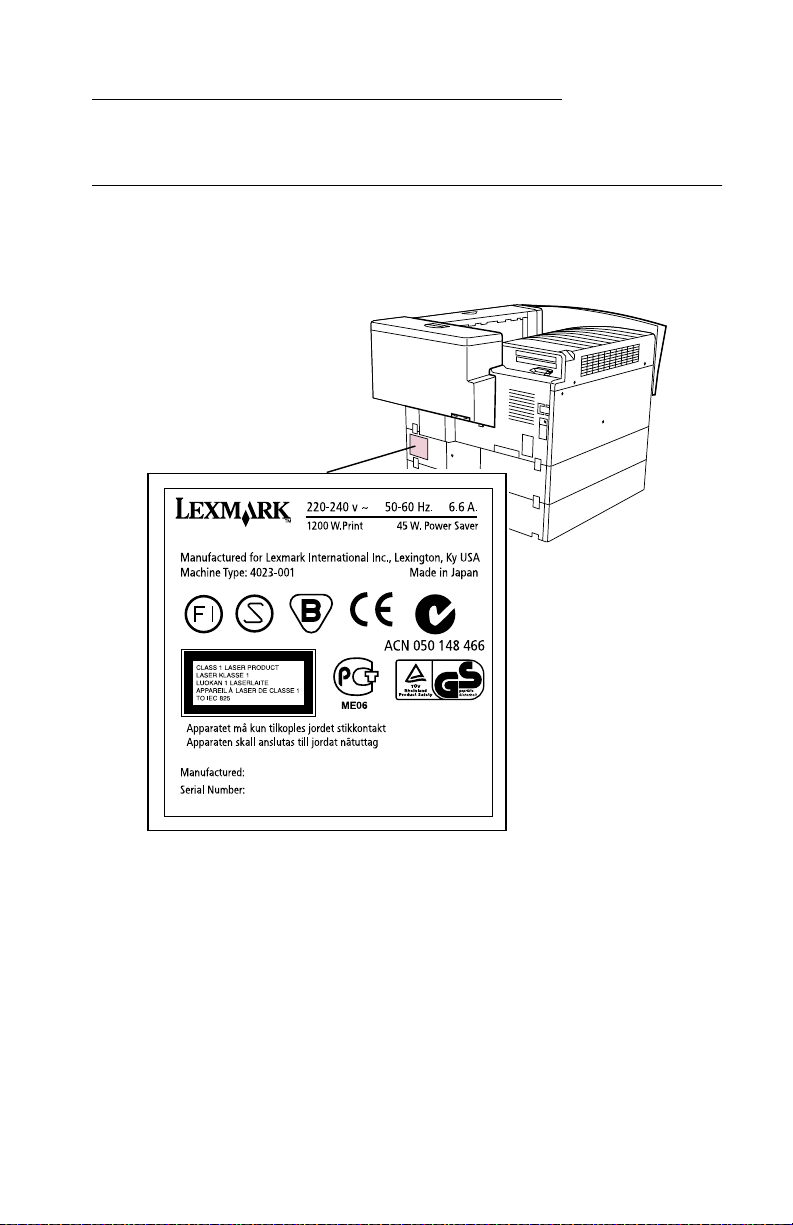
The following laser notice labels may be affixed to this printer as
shown:
Notices and Safety Information xiii
Page 14

4023-001
Laser Not ice
The printer is certified in the U.S. to conform to the requirements of
DHHS 21 CFR Subchapter J for Class I (1) laser products, and
elsewhere is certified as a Class I laser product conforming to the
requirements of IEC 60825.
Class I laser products are not considered to be hazardous. The
printer contains internally a Class IIIb (3b) laser that is nominally a 5
milliwatt gallium arsenide laser operating in the wavelength region of
770-795 nanometers. The laser system and printer are designed so
there is never any human access to laser radiation above a Class I
level during normal operation, user maintenance, or prescribed
service condition.
Laser
Avis relatif à l’utilisation de laser
German
Der Drucker erfüllt gemäß amtlicher Bestätigung der USA die
Anforderungen der Bestimmung DHHS (Department of Health and
Human Services) 21 CFR Teil J für Laserprodukte der Klasse I (1).
In anderen Ländern gilt der Drucker als Laserprodukt der Klasse I,
der die Anforderungen der IEC (International Electrotechnical
Commission) 60825 gemäß amtlicher Bestätigung erfüllt.
Laserprodukte der Klasse I gelten als unschädlich. Im Inneren des
Druckers befindet sich ein Laser der Klasse IIIb (3b), bei dem es
sich um einen Galliumarsenlaser mit 5 Milliwatt handelt, der Wellen
der Länge 770-795 Nanometer ausstrahlt. Das Lasersystem und der
Drucker sind so konzipiert, daß im Normalbetrieb , bei der Wartung
durch den Benutzer oder bei ordnungsgemäßer Wartung durch den
Kundendienst Laserbestrahlung, die die Klasse I übersteigen würde,
Menschen keinesfalls erreicht.
French
Pour les Etats-Unis : cette impri man te est certifiée conforme aux
provisions DHHS 21 CFR alinéa J concernant les produits laser de
Classe I (1). Pour les autres pays : cette imprimante répond aux
normes IEC 60825 relatives aux produits laser de Classe I.
xiv Service Manual
Page 15

4023-001
Les produits laser de Classe I sont considérés comme des produits
non dangereux. Cette imprimante est équipée d’un laser de Classe
IIIb (3b) (arséniure de gallium d’une puissance nominale de 5
milliwatts) émettant sur des longueurs d’onde comprises entre 770
et 795 nanomètres. L’imprimante et son système laser sont conçus
pour impossible, dans des conditions normales d’utilisation,
d’entretien par l’utilisateur ou de révision, l’exposition à des
rayonnements laser supérieurs à des rayonnements de Classe I .
Avvertenze sui prodotti laser
Questa stampante è certificata negli Stati Uniti per essere conforme
ai requisiti del DHHS 21 CFR Sottocapitolo J per i prodotti laser di
classe 1 ed è certificata negli altri Paesi come prodotto laser di
classe 1 conforme ai requisiti della norma CEI 60825.
I prodotti laser di classe non sono considerati pericolosi. La
stampante contiene al suo interno un laser di classe IIIb (3b)
all’arseniuro di gallio della potenza di 5mW che opera sulla
lunghezza d’onda compresa tra 770 e 795 nanometri. Il sistema
laser e la stampante sono stati progettati in modo tale che le
persone a contatto con la stampante, durante il normale
funzionamento, le operazioni di servizio o quelle di assistenza
tecnica, non ricevano radiazioni laser superiori al livello della classe
1.
Avisos so bre el láser
Se certifica que, en los EE.UU., esta impresora cumple los
requisitos para los productos láser de Clase I (1) establecidos en el
subcapítulo J de la norma CFR 21 del DHHS (Departamento de
Sanidad y Servicios) y, en los demás países, reúne todas las
condiciones expuestas en la norma IEC 60825 para productos láser
de Clase I (1).
Spanish
Italian
Los productos láser de Clase I no se consideran peligrosos. La
impresora contiene en su interior un láser de Clase IIIb (3b) de
arseniuro de galio de funcionamiento nominal a 5 milivatios en una
longitud de onda de 770 a 795 nanóme tros. El sistema láser y la
impresora están diseñados de forma que ninguna persona pueda
verse afectada por ningún tipo de radiación láser superior al nivel de
Notices and Safety Information xv
Page 16

4023-001
la Clase I durante su uso normal, el mantenimiento realizado por el
usuario o cualquier otra situación de servicio técnico.
Declaração sobre Laser
A impressora está certificada nos E.U.A. em conformid ade com os
requisitos da regulamentação DHHS 21 CFR Subcapítulo J para a
Classe I (1) de produtos laser. Em outros locais, está certif icada
como um produto laser da Classe I, em conformidade com os
requisitos da norma IEC 60825.
Os produtos laser da Classe I não são considerados perigosos.
Internamente, a impressora contém um prod uto lase r da C lass e IIIb
(3b), designado laser de arseneto de potássio, de 5 milliwatts
,operando numa faixa de comprimento de onda entre 770 e 795
nanómetros. O sistema e a impressora laser foram concebidos de
forma a nunca existir qualquer possiblidade de acesso humano a
radiação laser superior a um nível de Classe I durante a operação
normal, a manutenção feita pelo utilizador ou condições de
assistência prescritas.
Laserinformatie
De printer voldoet aan de eisen die gesteld worden aan een
laserprodukt van klasse I. V oor de Verenigde Staten zijn deze eisen
vastgelegd in DHHS 21 CFR Subchapter J, voor andere landen in
IEC 60825.
Dutch
Portugese
Laserproduk ten van klasse I worden niet als ongevaarlijk
aangemerkt. De printer is voorzien van een laser van klasse IIIb
(3b), dat wil zeggen een gallium arsenide- laser van 5 milliwatt met
een golflengte van 770-795 nanometer. Het lasergedeelte en de
printer zijn zo ontworpen dat bij normaal gebr uik, bij onderhoud of
reparatie conform de voorschriften, nooit blootstelli ng mogelijk is
aan laserstraling boven een niveau zoals voorgeschreven is voor
klasse 1.
xvi Service Manual
Page 17

4023-001
Lasermeddelelse
Printeren er godkendt som et Klasse I-laserprodukt, i
overenstemmelse med kravene i IEC 60825.
Klasse I-laserprodukter betragtes ikke som farlige. Printeren
indeholder internt en Klasse IIIB (3b)-laser, der nominelt er en 5
milliwatt galliumarsenid laser, som arbejder på bølgelængdeområdet
770-795 nanometer. Lasersystemet og printeren er udformet
således, at mennesker aldrig udsættes for en laserstråling over
Klasse I-niveau ved normal drift, brugervedligeholdelse eller
obligatoriske servicebetingelse r.
Danish
Notices and Safety Information xvii
Page 18

4023-001
Huomautu s las er laitteesta
Tämä kirjoitin on Yhdysvalloissa luokan I (1) laserlaitteiden DHHS
21 CFR Subchapter J -määrityksen mukainen ja muualla luokan I
laserlaitteiden IEC 60825 -määrityksen mukainen.
Luokan I laserlaitteiden ei katsota olevan vaarallisia käyttäjälle.
Kirjoittimessa on sisäinen luokan IIIb (3b) 5 milliwatin
galliumarsenidilaser, joka toimii aaltoalueella 770 - 795 nanometriä.
Laserjärjestelmä ja kirjoitin on suunniteltu siten, että käyttäjä ei
altistu luokan I määrityksiä voimakkaammalle säteilylle kirjoittimen
normaalin toiminnan, käyttäjän tekemien huoltotoimien tai muiden
huoltotoimien yhteydessä.
LUOKAN 1 LASERLAITE
V AROITUS! Laitteen käyttäminen muulla kuin tässä käyttöohjeessa
mainitulla tavalla saattaa altistaa käyttäjän turvallisuusluokan 1
ylittävälle näkymättömälle lasers äteilylle.
KLASS 1 LASER APPARAT
VARNING! Om apparaten används på annat sätt än i denna
bruksanvisning specificerats, kan användaren utsättas för osynlig
laserstrål ning, som överskrider gränsen för laserklass 1.
Finnish
VARO! Avattaessa ja suojalukitus ohitettaessa olet alttiina
näkymättömälle lasersäteilylle. Älä katso säteeseen.
VARNING! Osynlig laserstrålning när denna del är öppnad och
spärren är urkopplad. Betrakta ej strålen.
xviii Service Manual
Page 19

4023-001
Laser-notis
Denna skrivare är i USA certifierad att motsvara kraven i DHHS 21
CFR, underparagraf J för laserprodukter av Klass I (1). I andra
länder uppfyller skrivaren kraven för laserprodukter av Klass I enligt
kraven i IEC 60825.
Laserprodukter i Klass I anses ej hälsovådliga. Skrivaren har en
inbyggd laser av Klass IIIb (3b) som består av en laserenhet av
gallium-arsenid på 5 milliwat t so m arbe t ar i våglängdsområdet 770795 nanometer. Lasersystemet och skrivaren är utformade så att det
aldrig finns risk för at t n ågon person utsätts för laserstrålning över
Klass I-nivå vid normal användning, underhåll som utförs av
användaren eller annan föreskriven serviceåtgärd.
Laser-melding
Skriveren er godkjent i USA etter kravene i DHHS 21 CFR,
underkapittel J, for klasse I (1) laserprodukter, og er i andre land
godkjent som et Klasse I-laserproduk t i samsvar med kravene i IEC
60825.
Klasse I-laserprodukter er ikke å betrakte som farlige. Skriveren
inneholder internt en klasse IIIb (3b)-laser, som består av en
gallium-ar senlaserenhet som avgir stråling i bølgelengdeområdet
770-795 nanometer. Lasersystemet og skriveren er utformet slik at
personer aldri utsettes for laserstråling ut over klasse I-nivå under
vanlig bruk, vedlikehold som utføres av brukeren, eller foreskrevne
serviceopera sjoner.
Swedish
Norwegian
Notices and Safety Information xix
Page 20
4023-001
Avís sobre el Làser
Segons ha estat certificat als Estats Units, aquesta impressora
compleix els requisits de DHHS 21 CFR, apartat J, pels productes
làser de classe I (1), i segons ha estat certificat en altres llocs, és un
producte làser de classe I que compleix els requisits d’IEC 60825.
Els productes làser de classe I no es consideren perillosos. Aquesta
impressora conté un làser de classe IIIb (3b) d’arseniür de gal.li,
nominalment de 5 mil.liwats, i funciona a la regió de longitud d’ona
de 770-795 nanòmetres. El sistem a làser i la impressora han sigut
concebuts de manera que mai hi hagi exposició a la radiació làser
per s obre d’un nivell de classe I durant una operació normal, durant
les tasques de manteniment d’usuari ni durant els serveis que
satisfacin les condicions prescrites.
Catalàn
Japanese Laser Notice
xx Service Manual
Page 21
4023-001
Chinese Laser Notice
Korean La ser Notice
Notices and Safety Information xxi
Page 22

4023-001
Safety Information
• This product is designed, tested and approved to meet strict
global safety standards with the use of specific Lexmark
components. The safety features of some parts may not alway s
be obvious. Lexmark is not responsible for the use of other
replacement parts.
• The maintenance information for this product has been
prepared for use by a professional service person and is not
intended to be used by others.
• There may be an increased risk of electric shock and personal
injury dur ing disassem bly and ser v icing of this product.
Professional service personnel should understand this and take
necessary precautions.
Consignes de Sécurité
French
• Ce produit a été conçu, testé et approuvé pour respecter les
normes strictes de sécurité globale lors de l'utilisation de
composants Lexmark spécifiqu es. Les caractéristiques de
sécurité de certains éléments ne sont pas toujours évidentes.
Lexmark ne peut être tenu responsable de l'utilisation d'autres
pièces de rechange.
• Les consignes d'entretien et de répa ration de ce produit
s'adressent uniquement à un personnel de m aintenance
qualifié.
• Le démontage et l'entretien de ce produit pouvant présenter
certains risques électriques, le personnel d'entretien qualifié
devra prendre toutes les précautions nécessaires.
xxii Service Manual
Page 23

4023-001
Norme di sicurezza
Italian
• Il pr odotto è stato progettato, testato e approvato in conformità a
severi standard di sicurezza e per l’utiliz zo con componenti
Lexmark specifici. Le caratteristiche di sicurezza di alcune parti
non sempre sono di immediata comprensione. Lexmark non è
responsabile per l’utilizzo di parti di ricambio di altri produttori.
• Le informazioni riguardanti la manutenzione di questo prodotto
sono indirizzate soltanto al personale di assistenza autorizzato.
• Durante lo smontaggio e la manutenzione di questo prodotto, il
rischio di subire scosse elettriche e danni alla persona è più
elevato. Il personale di assistenza autorizzato, deve, quindi,
adottare le precauzioni necessarie.
Sicherheitshinweise
German
• Dieses Produkt und die zugehörigen Komponenten wurden
entworfen und getestet, um beim Einsatz die weltweit gültigen
Sicherheitsanforderungen zu erfüllen. Die sicherheitsrelevanten
Funktionen der Bauteile und Optionen sind nicht immer
offensichtlich. Sofern Teile eingesetzt werden, die nicht von
Lexmark sind, wird von Lexmark keinerlei Verantwortung oder
Haftung für dieses Produkt übernommen.
• Die Wartungsinformationen für dieses Produkt sind
ausschließlich für die Verwendung durch einen
Wartungsfachmann bestimmt.
• Während des Auseinandernehmens und der Wartung des
Geräts besteht ein zusätzliches Risiko eines elektrischen
Schlags und körperlicher Verletzung. Das zuständige
Fachpersonal sollte entsprechende Vorsichtsmaßnahmen
treffen.
Pautas de Seguridad
Spanish
• Este producto se ha diseñado, verificado y aprobado para
cumplir lo s más estrictos estándares de seguridad global
usando los componentes específicos de Lexmark. Puede que
las características de seguridad de algunas piezas no sean
Notices and Safety Information xxiii
Page 24

4023-001
siempre evidentes. Lexmark no se hace responsable del uso de
otras piezas de recambio.
• La in formaci ón sobre el mantenimiento de este producto está
dirigida exclusivamente al personal cualificado de
mantenimiento.
• Existe mayor riesgo de descarga eléctrica y de daños
personales durante el desmontaje y la reparación de la
máquina. El personal cualificado debe ser conscien te de este
peligro y tomar las precauciones necesarias.
Informações de Segurança
Portugese
• Este produto foi concebido, testado e aprovado para satisfazer
os padrões globais de segurança na utilização de componentes
específicos da Le xmar k. As funções de segurança de alguns
dos componentes podem não ser sempre óbvias. A Lexmark
não é responsável pela utilização de outros componentes de
substituição.
• As informações de segurança relativas a este produto
destinam-se a profissionais destes serv iços e não de vem s er
utilizadas por outras pessoas.
• Risco de choques eléctricos e ferimentos graves durante a
desmontagem e manutenção deste produto. Os profissionais
destes serviços devem estar avisados deste facto e tomar os
cuidados necessári os.
Informació de Seguretat
Catalàn
• Aquest producte està dissenyat, compr ovat i apro vat per tal
d'acomplir les estrictes nor me s de seguretat globals amb la
utililització de components específics de Lexmark. Les
característiques de seguretat d'algunes peces pot ser que no
sempre siguin òbvies. Lexmark no es responsabilitza de l'us
d'altres peces de recanvi.
• La in formaci ó pel manteniment d’aquest producte està
orientada exclusivament a professionals i no està destinada a
ningú que no ho sigui.
• El risc de xoc elèctric i de danys personals pot augmentar
durant el procés de desmuntatge i de servei d’aquest producte.
xxiv Service Manual
Page 25
4023-001
El personal professional ha d’estar-ne assabentat i prendre les
mesures convenients.
Chinese
Korean
Notices and Safety Information xxv
Page 26

4023-001
xxvi Service Manual
Page 27

4023-001
1. Gen e r a l Informat io n
Maintenance Approach
The diagnostic information in this manual leads you to the correct
field replaceable unit (FRU) or part. Use the error code charts,
symptom index, and service checks to determine the symptom and
repair the failure. You may find that the removals in the Repair
Information chapter w ill help you identify parts.
After you complete the repair, perform tests as needed to verify the
repair.
Tools
The removal and adjustment procedures described in this manual
require the following tools and equipment:
• Magnetic tip Phillips screwdrivers, large and small
• Flat-blade screwdrivers
• Analog volt ohmmeter (a digital volt ohmmeter may also be
used)
• Needle nose pliers
• Tweezers, C-ring pliers
When you make voltage readings, always use frame ground unless
another ground is specified.
General Information 1-1
Page 28
4023-001
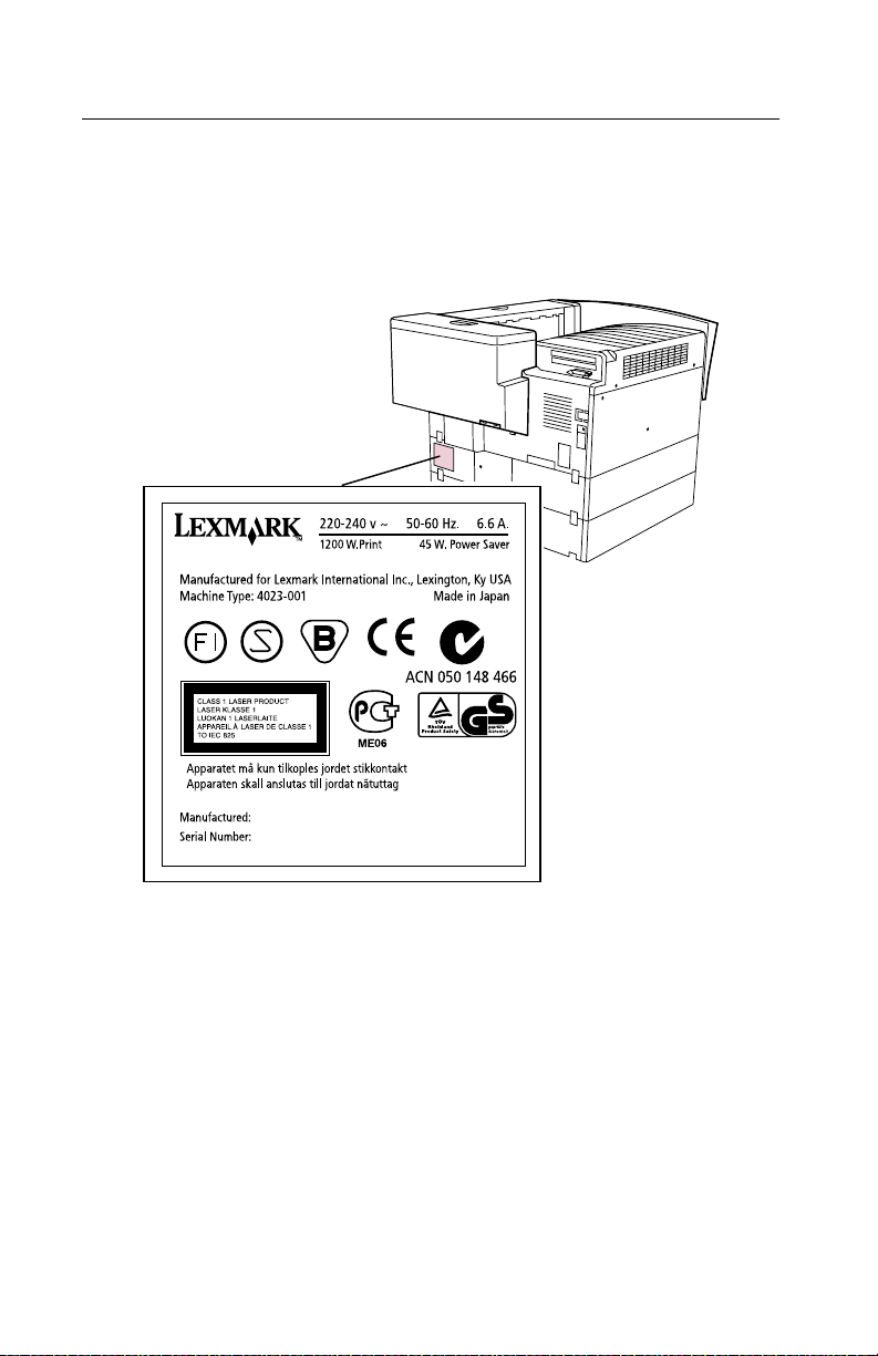
Serial Number
The serial number is located in the bottom left corner of the label
illustrated below:
1-2 Service Manual
Page 29

4023-001
Abbreviations
ASIC Application-Specific Integrated Circuit
CSU Customer Setup
DRAM Dynamic Random Access Memory
EEPROM Electrically Erasable Programmable Read-
Only Memo ry
EP Electrophotographic Process
ESD Electrostatic Discharge
FRU Fi eld Replacea ble Unit
HVPS High Voltage Power Supply
LAN Local Area Network
LASER Light Amplification by Stimulated Emission
of Radiation
LCD Liquid Crystal Display
LED Light-Emitting Diode
LVPS Low Vol tage Power Supply
NVRAM Nonvolatile Random Access Memory
OEM Original Equipment Manufacturer
PICS Problem Isolation Charts
PIXEL Picture Element
POR Power-On Reset
POST Power-On Self Test
PQET Print Quality Enhancem ent Technology
RIP Raster Image Processor
ROS Read-Only Storage
SRAM Static Random Access Memory
UPR Used Parts Replacement
VAC Volts alternating current
VDC Volts direct current
General Information 1-3
Page 30

4023-001
Standard Feat ures
Printer (Main)
Feature Description
Print speed 35 ppm (letter/A4) High Speed Printing
Power supply AC120V, AC220–240V ±10%
Power
consumption
Tempera tur e 10 to 35°C
Controller Lexmark Control ler (High Performance)
RIP page
storage
Printer
management
software
Operator panel Operator panel access for menus
Universal Drawer 250 sheet 11x17/A3/letter/legal/ A4
500 sheet input
drawers
Copy collation Multiple copy collation in the printer RAM
Dimensions 1.75 ft. (535 mm) Width x 2.06 ft. ( 628 mm) Depth x 1.40
Printing system Electrostatic dry powdered imaging system +
Exposure system Laser diode + polygon m irror scanning
Paper feeding
system
1200W
45W or less (low power)
Hard disk option can be partitioned to be used for
intermediate RIP page storage
Markvision
management
Two (2) 500 sheet input drawers (11x17/A3/letter/legal/
A4)
ft. (428 mm) Height
Imaging cartridge
Two-com ponent imaging cartridge
Six-way system Tray 1 (multipurpose) (250 sheet s)
TM
for network and/or desktop printer
Charging system Comb electrode with scorot ron system
Development MTHG system
Density
correction
Density control Developing bias adj usting system
ATDC sensor
1-4 Service Manual
Page 31

4023-001
Feature Description
Image transfer
system
PC drum Organic photoconductor (OPC)
Cleaning system Blade system
Separating
system
Fusing system Heat roller fusing system
Paper exit
system
Roller t ransform system
Paper separator
Printer
Face do wn (300 sheets maximum A4/C/Lett er C)
Mailbox
2000 sheets
Finisher
2500 sheets
500 sheets standard bin
2000 sheets fini sher bin
General Information 1-5
Page 32

4023-001
Options
Option Description
EDO DRAM
Memory
Options:
Hard disk Hard disk option
Tri-port interface
card
MarkNet
Adapters
Parallel
connector
Paper handling 500 sheet input tray and drawer
OptraImage
TM
S
32MB EDO Memory
64MB EDO Memory
Hard disk adapter cable
Serial, LocalTalk and IR A,B,C
Token-ring
Ethernet (10BT/100BTx)
Ethernet (10BT/2)
Ethernet (10BT/100BTx) SCSI
Coax/twinax adapter for SCS
Parallel/USB A,B,C
2500 sheet input tray (worldwide)
2000 sheet mailbox
2500 sheet finish er (3 and 4 hole
punching capability, 5k stapling capacity)
TM
Ethernet 10/100, SCSI
scanner and fax
Optra W810
Versions*
A,B,C
A,B,C
B,C
A,B,C
A,B,C
Supplies Photoconductor kit
Toner cartridge
Staples
Cables 10-foot par allel cable
20-foot par allel cable
50-foot serial cable
10-foot 1284 A-C parallel cable
*Versions are:
A–W810
B–W810n
C–W810dn
1-6 Service Manual
A,B,C
A,B,C
Page 33

4023-001
Printer/Options
Parts Identification
General Information 1-7
Page 34

4023-001
Printer Configuration
The following diagram shows the major parts of the printer and
paper path. The printer consists of the paper feed section, printhead
unit (exposure section), imaging cartridge (charging section and
development section), image transfer section, fusing section,
cleaning section and paper exit section.
1 Paper Exit Roller 12 Double Feed Sensor
2 Paper Exit Sensor (PS3) 13 Tray1 (1st Paper Cassette)
3 Lower Fusing Roller 14 1st Paper Cassette Near Empty Sensor
4 Upper Fusing Roller (Heater Lamp) 15 1st Paper Cassette Empty Sensor (PC4)
5 Image Transfer Roller 16 ATDC Sensor
6 Synchronizing Roller 17 Sleeve Roller
7 Synchronizing Roller Sensor (PC2) 18 P C Drum Charger
8 Manual Unit 19 PC Drum
9 Tray2 (2nd Paper Cassette) 20 Imaging Cartridge
10 2nd Paper Cassette Near Empty Sensor
(PC25)
11 2nd Paper Cassette Empty Sensor (PC22) 22 Laser Beam
(PC5)
21 Print Head Unit (PH)
1-8 Service Manual
Page 35

4023-001
General Des crip tio n of Each Sectio n
Paper Feed Section
Paper feeds from tray 1 (1st paper cassette), tray 2 or 3 (500-sheet
paper cassette). When the printer receives a print command, the
transport motor M2 turns, paper take-up solenoid turns ON, and the
paper take-up roller in the 1st paper cassette feeds a sheet of paper.
The synchronizing roller sensor (PC2) detects the fed paper and the
paper is then fed to the synchronizing roller fo r printing. When paper
trays (500-sheet cassette (tray 2 or 3), 250-sheet universal cassette
(tray 1)), or 2500-sheet drawer is installed, paper feeds from the
respective paper source.
Printhead Unit (Exposure Section)
The laser diode in the printhead unit emits a laser beam. The
scanning beam creates an electrostatic latent image on the surface
of the PC drum in the imaging cartridg e.
Imaging Cartridge (Charging, Development Section)
The imaging car tr idge consist s of the charging section and
development section. The I/C drive motor (M1) drives the moving
parts of the imaging cartridge.
Image Transfer Section (Release Section)
The toner image on the PC drum transfers to the paper when
passing over the transfer roll. The paper electrostatically releases
from the PC drum.
Fusing Section
Using a heated roller , the fusing section permanently fixes the toner
image onto the paper. A heat sensitive element (thermistor)
attached to the upper fusing roller controls the fusing temperature.
Cleaning Section
The cleaning blade removes excess toner from the paper and
transfers the toner to the waste toner box.
General Information 1-9
Page 36

4023-001
Paper Exit Section
After the paper passes the fusing section, the paper exit roller ejects
the paper out the top of the printer. The paper exit sensor (PC3)
senses the ejection of the paper.
Optional manual and duplex unit installed:
The duplex unit switchback motor pulls the trailing edge of the
printed paper inside the duplex unit. The duplex unit transport motor
then feeds the paper to the manual unit where the paper remains
until the second print command.
General Flow for Printing Process
Print command
Polygon Motor ON
Cleaning The transfer roll er becomes negatively
Starting processing The I/C (imaging cartridge) drive motor (M1)
Paper take-up The transport motor (M2) starts turning.
Laser emission A laser beam is emitted at constant power.
Scanning the image dat a
Paper feeding
Dev eloping the image data T one r is applied to the PC drum to produce a
Transfer the image data The toner image on the surface of the PC
Fusing the toner The toner is permanently fixed onto the
Cleaning Excess toner and electric potential on the
Paper ejection The paper ejects.
The motor in the printhead unit starts
turning.
charged to prevent the negat ively-charged
toner from sticking to the PC Drum.
starts turning.
The paper take-up solenoid turns on to feed
paper.
A laser beam scans the sur face of the PC
drum to produce a latent elect rostatic image.
The syc hroniz ing r olle r sen sor (PC2) d etects
the presence of paper. The sychronizing
clutch then turns on which turns on the
sychronizing roller for feeding paper.
visibl e toner image.
drum is transferred onto the paper.
paper.
PC drum are eliminated .
1-10 Service Manual
Page 37

4023-001
Paper Feed Section
Taking Up Paper–Tray 1 (1st Paper Cassette)
Power is transmitted from the transport motor (M2) as follows to take
up paper from the 1st paper cassette:
1. The transport motor (M2) tur n s counterclockwise.
2. The idle gear turns clockwise and the 1st cassette paper takeup solenoid (SL1) turns ON.
3. The paper take-up roller turns counterclockwise and paper is
taken up.
1 PC Drum 5 Synchronizing Roller
2 Image Transfer Roller 6 Paper Take-Up Roller
3 Transport Motor (M2) 7 Paper
4 Synchronizing Roller
Sensor (PC2)
General Information 1-11
Page 38

4023-001
Tray 1 Sensors
1 1st Cassette Paper Near Empty Sensor (PC5) 5 Synchronizing Roller Sensor (PC2)
2 1st Cassette Set Sensor (PC6) 6 Double Feed Sensor
3 1st Cassette Paper Take-up Solenoid (SL1) 7 Paper Take-up Roller
4 Separator Pad 8 1st Paper Cassette Empty Sensor (PC4)
1st Cassette Tray 1 Set Sensor (PC6)
PC6 (1) sensor detects installation of the 1st paper cassette in tray
1.
.
1 1st Cassette Set Sensor (PC6)
2 1st Paper Cassette
1-12 Service Manual
Page 39

4023-001
1st Cassette Tray 1 Paper Empty Sensor (PC4)
PC4 (1) detects paper empty status of the 1st paper cassette.
.
1 1st Paper Cassette Empty Sensor (PC4)
2 Paper
1st Cassette Tray 1 Paper Near Empty Sensor (PC5)
PC5 detects when the 1st cassette is near empty.
1 1st Paper Cassette Near Empty Sensor (PC5)
2 Paper
3 Paper Lifting Plate
General Information 1-13
Page 40

4023-001
1st Cassette Tray 1 Double Feed Sensor
The double feed sensor (located on the double feed detecting
sensor board (PWB-H)) detects the possibility of double feed. This
sensor uses a photo reflector.
The double feed sensor detects whether the leading edge of paper
to be taken up next runs 10 mm or more from the paper nip point. If
paper runs 10 mm or more, double feeding may occur if the paper is
taken up in the normal printing interval. To avoid this, the printer
prolongs the printing intervals as long as the double feed sensor
detects a double feed status. This results in the reduction of the
number of sheets fed per minute.
Light reflects: Output=L Light does not reflect: Output=H
1 Paper
2 Paper Take-up Roller
3 Double Feed Sensor
1st Cassette Tray 1 Synchronizing Roller Sensor (PC2)
This sensor detects that the paper is fed inside the printer.
1 Synchronizing Roller Sensor (PC2)
2 Paper
1-14 Service Manual
Page 41

4023-001
1st Cassette Tray 1 Paper Size Detection
Five DIP switches indicate the paper size for the 1st paper cassette.
Four of the switches indicate length and one width. The DIP
switches are located on the 1st cassette paper size board (PWBS1).
The ON(1)/OFF(2) settings of the length dip switches set the analog
input voltage. The input voltage and the normal input data from the
width dip switch port determine paper size.
The precise paper size cannot be identified by detection and must
be selected from the operation panel.
When no cassette is set, all switches are set to off.
General Information 1-15
Page 42

4023-001
Tray 2 (2nd Paper Cassette)
1 2nd Cassette Paper Empty Sensor (PC22) 4 2nd Cassette Right Door Detecting Sensor
2 2nd Cassette Paper Near Empty Sensor (PC25) 5 Paper Take-Up Roller
3 2nd Cassette Paper Take-up Solenoid (SL21)
(PC23)
Taking up Paper–Tray 2 (2nd Paper Cassette)
Power transmits from the transport motor (M2) as follows to take up
paper from the 2nd paper cassette:
1. The transpor t motor (M2) turns counterclockwise.
2. The idle gear turns clockwise.
3. The 1st cassette paper take-up gear turns counterclockwise.
4. The 1st cassette idle gear turns clockwise and the transport
clutch (CL1) turns ON.
5. Power is transmitted to the 2nd paper cassette.
a. The 2nd cassette paper take-up solenoid (SL21) turns ON.
b. Paper take-up roller turns counterclockwise.
c. Paper is taken up.
1-16 Service Manual
Page 43

4023-001
1 PC Drum 6 Paper
2 Image Transfer Roller 7 Paper Take-up Roller
3 Transport Motor (M2) 8 Transport Clutch (CL1)
4 Synchronizing Roller Sensor
(PC2)
5 Transport Gear
9 Synchronizing Roller
General Information 1-17
Page 44

4023-001
Tray 2 Sensors
2nd Cassette Detection
This sensor detects installation of the 2nd paper cassette in tray 2.
The paper size indicated by the 2nd cassette paper size board
(PWB-S2, -S3) is also checked. The length dip switch setting
determines paper size.
2nd Cassette Paper Empty Sensor (PC22)
PC22 detects the paper empty status of the 2nd paper cassette.
Paper empty status occurs when paper runs out in the 2nd paper
cassette.
1 2nd Cassette Paper Near Empty Sensor (PC22)
2 Paper
1-18 Service Manual
Page 45

4023-001
2nd Cassette Paper Near Empty Sensor (PC25)
PC25 detects paper near empty status of the 2nd cassette.
1 2nd Cassette Paper Near Empty Sensor (PC25) 3 Paper Lifting Plate
2 Paper
2nd Cassette Right Door Detecting Sensor (PC23)
PC23 detects if the 2nd cassette right door is open or closed. The
right door is normally closed except when removing jammed paper.
1 2nd Cassette Right Door Detecting Sensor (PC23)
2 Right Door
General Information 1-19
Page 46

4023-001
Edge Guide and Trailing Edge Stop
Universal Cassette/500-Sheet Tray 2 & 3
The edge guide and trailing edge stop of the universal cassette slide
to accommodate different paper sizes.The edge guide and trailing
edge stop of the fixed paper size cassette are attached in fixed
positions.
Fixed Paper Size Cassette
Paper Lifting Plate
Two paper lifting springs in each cassette constantly raise the paper
lifting plate.
1-20 Service Manual
Page 47

4023-001
Cassette-in-Position Detection
The rib on the cassette frame presses the cassette set switch on the
back panel of the printer, indicating the cassette is inserted. The
position of the rib on the cassette frame is different between the
fixed paper size and universal cassette. This lets the printer detect
which cassette is inserted.
General Information 1-21
Page 48

4023-001
Paper Near Empty Detection
Height of the paper lifting plate determines paper-near-empty
condition. Since the amount of paper available during the take-up
sequence varies, detection occurs when the paper take-up roll is in
the retracted position.
1-22 Service Manual
Page 49

4023-001
Paper Empty Detection
When the cassette runs out of paper, the actuator of the paper
empty sensor drops into the cutout of the paper lifting plate. This
exposes the sensor, signaling that the cassette is out of paper.
General Information 1-23
Page 50

4023-001
Paper Separating Mechanism
Each cassette has fingers that separate the top sheet of paper from
the rest of the paper stack during paper take-up. When the paper
take-up roll starts to turn, the turning force transmits to the top sheet
of paper. The transmitted force overcomes the block of the fingers,
causing the top sheet of paper to ride over the fingers and feed out
of the cassette into the printer. The paper transport force obtained
through friction with the top sheet of paper is weak and does not
allow the second sheet of paper to ride over the block of the fingers.
1-24 Service Manual
Page 51

4023-001
Paper Take-Up Roll
Two paper take-up rolls are mounted in both the fixed paper size
cassette and universal cassette. As the take-up solenoid energizes,
the spring tension increases, meshing the drive and clutch gear
which transmits drive to the paper take-up rolls.
General Information 1-25
Page 52

4023-001
Paper Feed
The paper taken up by the paper take-up section feeds to the
transfer section after registration compensation.
Registration Compensation
Registration compensation eliminates paper skew by controlling the
paper take-up roller and synchronizing roller rotation timing.
The taken-up paper passes the synchronizing roller sensor (PC2)
and reaches the synchronizing roller. The printer delays the
synchronizing roller to align the leading edge of the paper with the
stopping synchronizing roller. The leading edge of the paper slacks
a little as shown in the figure. The synchronizing clutch (CL1)
activates and the paper take-up roller turns for a moment to securely
feed the paper to the inside of the printer.
1 Slack of Paper 4 Synchronizing Roller Sens or (P C2)
2 Synchronizing Roller 5 Paper
3 Transport Motor (M2) 6 Paper Take-up Roller
Paper Feeding
1. The transpor t motor (M2) turns counterclockwise.
2. The idle gear turns clockwise. The synchronizing clutch (CL1)
turns. The I/C drive motor (M1) drives the PC drum.
As the PC Drum turns, the transfer roller also turns.
1-26 Service Manual
Page 53

4023-001
The synchronizing roller feeds paper to the PC drum and transfer
roller. The PC drum and transfer roller pinch the paper and feed it to
the fusing section.
1 PC Drum 4 Synchronizing Clutch (CL1)
2 Image Transfer Roller 5 Paper
3 Transport Roller 6 Synchronizing Roller
General Information 1-27
Page 54

4023-001
Printhead Unit (Exposure section)
The printhead unit incorporates a laser diode that emits a laser
beam corresponding to the print image data.
The scanning laser beam scans the PC drum from left to right,
producing an electrostatic latent image on the surface of the PC
drum.
Imaging Cartridge (Charging/Development Section)
The printer main body I/C drive motor (M1) transmits power to the
gears of the imaging cartridge. The I/C drive motor (M1) turns
clockwise (as viewed from the front of the printer).
1-28 Service Manual
Page 55

4023-001
Part Name Function
1 Waste toner box Collects excess toner.
2 Transf er screw Transfers exc ess toner to the
3 Rotary blade Transfers the waste toner
4 Separating claw Ensures paper release fro m the
5 Cleaning blade Removes excess toner from the
6 Sheet erase Negatively charges the PC Drum
7 PC drum Charged roller that applies image
8 Sleeve roller Transfers toner to the su rface of
9 Screw Mixe s toner and carrier inside the
10 ATDC Sensor Adjusts the toner density.
waste toner box.
collected by the cleaning blade to
the waste toner box.
PC Drum.
PC Drum (waste toner) aft er
transfer to the paper.
to eliminate the remaining elect ric
polarity after tr ansfer to the paper.
to paper.
the PC Drum via a rotating resin
sleeve and then dev elops it.
toner hopper.
11 Toner fil ler opening Toner is supplied from the sub-
hopper.
12 Charger Charges the PC Drum.
General Information 1-29
Page 56

4023-001
Development Section
Development
The development section feeds toner to the electrostatic latent
image on the surface of the PC drum to produce a visible toner
image.
A screw circulates the toner in the toner hopper. The toner mixes
with the carrier to produce the developer. The ATDC sensor detects
the ratio of toner to carrier, and voltage controls the toner density.
The developer is then supplied to the sleeve roller.
The sleeve roller negatively charges the toner. The toner adheres to
the electrostatic latent image due to the reduced negative voltage in
the image area. The toner does not adhere to the area where the
laser beam has not been applied. This occurs because the charge
brush maintains the negatively charged voltage in the non-image
area.
1-30 Service Manual
Page 57

4023-001
1 Laser Beam 4 ATDC Sensor
2 PC Drum 5 Screw
3 Sleeve Roller 6 Developer
General Information 1-31
Page 58

4023-001
Toner Empty Detection
Three empty-toner conditions are detected: sub-hopper empty, toner
bottle near empty, and toner bottle empty.
Sub-Hopper Empty
The toner detection plate lead switch checks the toner level by
detecting the position of the toner detection plate.
The toner bottle supplies toner to the rotating mixing plate. The
rotating mixing plate spreads the toner evenly in the sub-hopper .
The toner pushes upward on the toner detection plate. The position
of the toner detection plate indicates the amount of toner in the subhopper.
A toner empty status occurs when the toner detection plate lowers
enough for the lead switch to detect the plate. However, the lead
switch is not activated when the toner supply motor stops or the
bottle motor rotates. When the sub-hopper empty status occurs, the
bottle motor activates to supply toner to the sub-hopper from the
toner bottle.
.
1 Toner Detection Plate 3 Rotating Mixing Plate
2 Toner Detection Plate Read
Switch
1-32 Service Manual
Page 59

4023-001
Toner bottle near empty
The toner bottle empty status is detected when the toner bottle
rotates and feeds toner to the sub-hopper. The bottle rotation
counter checks the number of bottle rotations. If the number of
rotations exceeds 10, the near empty status occurs. The bottle
supplies toner after the near empty status occurs.
Toner bottle empty
The toner bottle empty status in the imaging cartridge occ urs when
the ATDC sensor detects a toner density (ratio of toner to carrier)
below 10%. When this occurs, the appropriate toner density cannot
be maintained. The bottle motor and toner supply motor stop. The
toner empty status is recorded and will not reset until the toner
cartridge is replaced.
A TDC Sensor
The developer, circulated by a screw, passes over the ATDC sensor.
The sensor measures the ratio of toner to carrier (T/C ratio) in the
developer . This ratio is converted to a charge and input to PWB-A.
When the sensor detects a low T/C ratio, T/C recovery mode begins.
General Information 1-33
Page 60

4023-001
Image Transfer Section (Release Section)
The transfer roller transfers the toner image on the surface of the PC
Drum onto the paper.
Normally the paper separates from the PC drum without any outside
interference. When the paper fails to separate from the PC drum, the
separating claw releases the paper by force.
1 PC Drum
2 Image Transfer Roller
3 Paper
1-34 Service Manual
Page 61

4023-001
Optical Erase
During the optical erase, light from the eraser lamp irradiates the PC
drum, eliminating the negative charge applied by the cleaning blade
during PC drum cleaning. This prevents blac k lines from being
created on the front and rear ends and both sides of the image.
1 Cleaning Blade
2 Optical Erase
General Information 1-35
Page 62

4023-001
Fusing Section
Fusing
Toner-transferred paper feeds from the transfer section to the fusing
section when power from the transport motor (M2) transmits to the
upper fusing roller.
The fusing roller heater lamp (H1, built in the roller) heats the upper
fusing roller. The fusing roller thermistor (TH1) attached to the upper
fusing roller controls the heater temperature. To ensure overheating
does not occur, the fusing roller thermostat (TS1) and fusing roller
heater lamp fuse (TF1) are connected in series to the heater lamp
(H1). The heater lamp (H1) heats when an AC voltage is applied.
1 Separator 5 Upper Fusing Roller
2 Thermostat (TS1) 6 Paper
3 Thermistor (TH1) 7 Lower Fusing Roller
4 Heater Lamp (H1) 8 Guide
Temperature Control Using The Thermistor
The resistance of the thermistor (TH1) attached to the upper fusing
roller varies with temperatures. When temperature rises, the
resistance of the thermistor (TH1) decreases, and vice versa.
Thermostat (TS1) and Heater Lamp Fuse (TF1)
If an abnormal current flows into the heater lamp because of
thermistor trouble and the upper fusing roller temperature reaches
1-36 Service Manual
Page 63

4023-001
approximately 220°C, the contact of the thermostat automatically
opens to shut off AC voltage. (As the temperature decreases, the
contact of the thermostat closes again. However, once the
thermostat activates, you must replace it with a new one.) The
thermostat cannot respond quickly enough to protect against a
sudden overload current. In this case, the heater lamp fuse blows to
protect the heater lamp.
Fusing Temperature Control
The fusing section start s to warm up when the main switch turns
ON. Preliminary rotation occurs for 20 seconds when the
temperature of the upper fusing roller reaches 170°C (338°F). When
the rotation stops, the temperature of the upper fusing roller is
approximately 200°C (392°F) and warm-up is complete. (Warm-up
takes approximately 1 minute.)
Fusing PPM Control
The sides of the fusing roller become excessively hot when small
sheets of paper (paper width of 250 mm (9-3/4") or less) print
continuously. When this occurs, "fusing PPM control" activates to
maintain specific paperfeed intervals and prevent the roller from
becoming too hot.
General Information 1-37
Page 64

4023-001
Paper Exit Section
Paper Path Through Exit
Paper fed from the fusing section passes through the paper exit
roller and ejects printed-side down out the top of the printer. The
transport motor (M2) provides transmit power for feeding paper.
The paper exit sensor (PC3) detects paper eject. As paper passes
through the sensor, it presses the sensor arm until the sensor arm
end engages with the photointerrupter.
1 Paper Exit Sensor (PC3)
2 Paper
1-38 Service Manual
Page 65

4023-001
1 Paper 6 Synchronizing Roller
2 Paper Exit Roller 7 Transport Motor (M2)
3 Paper Exit Sensor (PC3) 8 PC Drum
4 Lower Fusing Roller 9 Upper Fusing Roller
5 Synchronizing Roller Sensor (PC2)
Detection of a New Imaging Cartridge
The printer checks for a new imaging cartridg e when:
• The printer is turned on after installing a new imaging cartrid ge.
• With the printer turned on, the right door is closed after
replacing the imaging cartridg e.
The imaging car tr idge has an activating fuse. When the printer is
turned ON, the fuse is blown and the PC drum counter clears,
enabling detection of the image cartridge life. When power is turned
OFF, the counter value is stored in the imaging cartridge EEPROM.
When power is turned ON, the counter value is recalled from the
imaging cartridge EEPROM to continue counting.
General Information 1-39
Page 66

4023-001
Right Door Interlock Switch (S2)
The right door is normally closed. It is open when the imaging
cartridge is replaced or jammed pape r is removed.
With the door closed, the projection of the right door presses the
spring attached to the switch lever, turning the switch ON. When it is
opened, the lever of the switch is released, turning the switch OFF.
1 Right Door 3 Right Door Interlocks
2 Projection 4 Spring
1-40 Service Manual
Page 67

4023-001
Duplex Unit Option
Parts Identification
General Information 1-41
Page 68

4023-001
Cross-Sectional View
1 Duplex Unit Transport Roller 1 3 Duplex Unit Transport Roller 2
2 Duplex Unit Transport Roll 1 4 Duplex Unit Transport Roll 2
Switchback Mechanism
Switchback Operation
To accomplish the switchback operation, the switchback motor
reverses the rotational direction of the paper exit roller. The onesided print then feeds into the duplex unit. The drive of the
switchback motor is transmitted through a gear train.
1-42 Service Manual
Page 69

4023-001
Paper Exit Roller Drive Coupling Mechanism
When the duplex unit is mounted, the tip of the duplex unit lever
raises the idle lever. This disconnects the printer drive (fusing roller)
from the paper exit roller and connects the switchback motor drive.
Switchback Motor Control
The switchback motor is a two-phase stepping motor.
Transport and Dupl ex Paper Take-Up Mechanism
Transport and Duplex Paper Take-Up Operation
The transport and duplex paper take-up operations are performed by
two pairs of duplex unit transport rollers/rolls and the manual feed
paper take-up roll of the printer. The drive for these operations
comes from the duplex unit transport motor and manual feed paper
take-up clutch.
General Information 1-43
Page 70

4023-001
Duplex Unit Transport Motor Control
The duplex unit transport motor is a two-phase stepping motor.
1-44 Service Manual
Page 71

4023-001
Paper Deck 2500-Sheet (LCC) Option
Cross-Sectional View
1 Lift 2 5 Vertical Transport Roller
2 Paper Take-Up Roll 2 6 Vertical Transport Roll
3 Lift 1 7 Feed Roll
4 Paper Take-Up Roll 1 8 Separator Roll
Vertical Transport Drive Mechanism
Vertical Transport Drive Operation
The Vertical T r ansport Roller is driven by LCC (paper deck) transport
motor (HMOT). The driving force of HMOT is transmitted via a gear
train and registration clutch (RCL) to the vertical transport roller
which feeds the paper from lift 1 or 2 to the printer. Because of the
long paper path from lift 2, skew tends to occur in the paper fed from
General Information 1-45
Page 72

4023-001
lift 2. To correct skew, RCL forms a loop in the paper between the
separator roll and vertical transport roller.
Control of LCC Transport Motor HMOT
The printer main engine board energizes and de-energizes HMOT
by sending signals to HMOT through the LCC (paperdeck) main
board (PWB-A). HMOT is a DC motor .
1-46 Service Manual
Page 73

4023-001
Paper Take-Up Mechanism
The paper take-up mechanism takes up a sheet of paper from the
paper stack on each lift and feeds it to the vertical transport roller.
A paper take-up sequence occurs when drive from LCC Transport
Motor HMOT transmits through take-up clutch 1/2 P1CL/P2CL to
paper take-up roll 1/2. When lift 1 runs out of paper, paper feeds
from lift 2.
A roll with a torque limiter prevents double feed of the last two sheets
of paper. The roll is mounted beneath paper take-up roll 1 of lift 1.
Paper take-up roll 1 is active when paper is fed from lift 1.
Both paper take-up roll 1 and 2 activate to perform the paper take-up
sequence when paper feeds from lift 2. During this sequence, paper
empty sensor 1 PPS1 detects proper feed of paper through take-up
roll 1.
The sheet of paper taken from lift 1/2 temporarily stops at the paper
standby position sensor to minimize variations in the position of the
leading edge of the paper. Separator clutch BCL transmits drive to
the separator roll which moves the sheet of paper to the vertical
transport section.
General Information 1-47
Page 74

4023-001
Paper Take-Up From Lift 1
After Lift 1 completes lifting motion, paper take-up roll 1 takes-up
and feeds a sheet of paper until the paper blocks paper standby
position sensor S1. This serves as the standby position of the paper.
When the printer sends a paper take-up signal, the separator/feed
rolls and paper take-up roll 1 transport s the paper up to registration
sensor RSEN. After RSEN has been blocked, the paper moves a
1-48 Service Manual
Page 75

4023-001
little further to reach the vertical transpor t roller, and forms a
registration loop, before stopping.
The vertical transport roller transports the paper to the printer. When
the trailing edge of the paper being transported by the vertical
transport roller unblocks paper standby position sensor S1, the
subsequent sheet of paper is transpor ted to the standby position
and the LCC waits for the next paper take-up signal.
Registration clutch RCL de-energizes a given period of time after the
trailing edge of the paper being taken up unblocks registration
sensor RSEN. The next paper take-up signal transmits after the
timer (which starts when the vertical transport roller rotates for the
preceding sheet of paper) runs out.
General Information 1-49
Page 76

4023-001
Paper Take-Up From Lift 2
After all sheets of paper have been taken up and fed from lift 1, lift 1
moves to the top level position to serve as part of the paper path for
feeding paper from lift 2.
After the trailing edge of the last sheet of paper from Lift 1 unblocks
paper empty sensor 1 PPS1, both paper take-up roll 1 and 2 turn.
Paper take-up roll 1 and 2 transports the sheet of paper until the
paper blocks LCC take-up sensor PPS0.
Paper take-up roll 1 transports the paper located at PPS0 until the
paper blocks paper standby position sensor S1. This is the standby
position of the paper.
1-50 Service Manual
Page 77

4023-001
After the printer sends a paper take-up signal, the separator/feed
rolls and paper take-up roll 1 transports the paper until the paper
blocks registration sensor RSEN. The paper travels a little further to
reach the vertical transport roller and form a registration loop before
stopping. The vertical transport roller transports the paper to the
printer.
After the trailing edge of the paper transported by the vertical
transport roller unblocks paper empty sensor 1 PPS1, paper take-up
roll 1 and 2 transport the subsequent sheet of paper until the
subsequent sheet of paper blocks PPS1.
General Information 1-51
Page 78

4023-001
If PPS0 is unblocked and a sheet of paper is blocking PPS1, the
sheet of paper blocking PPS1 transports to the standby position
uninterrupted. LCC then waits for the next paper take-up signal.
Registration clutch RCL de-energizes a given period of time after the
trailing edge of the paper being taken-up unblocks registration
sensor RSEN. The next paper take-up signal transmits after the
timer (which starts when the vertical transpor t roller rotates for the
preceding sheet of paper) runs out.
Paper Take-Up Retry Control
To minimize the occurrence of paper misfeed due to a slippery paper
take-up roll, separator clutch BCL energizes again if a sheet of
paper fails to reach registration sensor RSEN within a given period
of time after BCL first energizes.
1-52 Service Manual
Page 79

4023-001
Paper Separating Mechanism
The paper separating mechanism employs a system with a torque
limiter that is fitted to the separator roll shaft. It stops the separator
roll when friction changes between the feed and separator rolls.
Paper Pressure Releasing Mechanism
When LCC is pulled out, the pressure release rail pushes the
separator roll assembly downward, releasing the pressure between
the feed and separator roll. The pressure release rail is located
above the rail on the paper take-up end.
General Information 1-53
Page 80

4023-001
Paper Take-Up Roll Retracting Mechanism
When LCC is slid out, the projection on the back of the LCC front
cover disengages from the pressure release lever . This pushes the
paper take-up roll upward, releasing pressure between the paper
and paper take-up roll.
Edge Guides and Trailing Edge Stop
The trailing edge stop screws into position (not used for letter
crosswise). Edge guides slide into any position you want.
Whenever the positions of the edge guides and trailing edge stop
change, be sure to perform the paper size setting procedure. (See
“Paper Size Setting” that follows.)
1-54 Service Manual
Page 81

4023-001
Paper Size Setting
The paper sizes that can be set are A4 crosswise and Letter
crosswise.
After the positions of the edge guides and trailing edge stop change,
place the DIP switch keys on LCC main engine board PWB-A in the
corresponding positions according to the current paper size
Note: Positions 3 and 4 are not used.
SW1 Letter Crosswise A4 Crosswise
1OFF ON
2OFF OFF
3OFF OFF
4OFF OFF
General Information 1-55
Page 82

4023-001
LCC-in-Position Detection
The LCC is detected at its closed position when the light blocking
plate located on the rear end of the right rail blocks LCC Set Sensor
FRONT.
Lifting Mechanism
When the LCC is slid into the printer, the couplings engage. The
LCC lift-up motor EMOT rotates forward and backward, turning the
one-way gear and gear train to raise Lift 1 and Lift 2 respectively.
Lift 1 and 2 drive mechanisms each contain a one-way gear. When
EMOT turns forward, drive transmits to Lift 1 and when the motor
turns backward, drive transmits to Lift 2.
1-56 Service Manual
Page 83

4023-001
o
o
Lifting Operations
LCC set sensor FRONT is blocked.
LCC lift-up motor EMOT turns forward raising lift
1.
The paper stac k caus es the li gh t blo c ki ng pla te
the pape r take-up roll 1 assembly to block lift-up
sensor 1 LS1.
EMOT de-energizes and then energizes to start
turning backward, raising Lift 2.
The paper stac k caus es the li gh t blo c ki ng pla te
the pape r take-up roll 2 assembly to block lift-up
sensor 2 LS2.
EMOT de-ener gizes.
Paper is consumed as print cycles run.
The paper take-up roll gradually lowers, unblocking the lift-u p Sensor.
EMOT energizes and the lift raises. This lifts the
paper stack to block the lift- up sensor.
General Information 1-57
Page 84

4023-001
Both lift 1 and 2 perform the following sequence of operations to
maintain pressure between the paper and paper take-up roll.
1. Lift 1 and 2 ascends.
• LCC is slid into position.
• The lift-up sensor is unblocked while a paper take-up
sequence occurs with paper present on the lift.
2. Lift 1 and 2 stops.
• Lift-up sensor is blocked.
• The paper stack top level position is being corrected.
3. LCC lift-up motor EMOT energizes.
4. Lift 1 and 2 descends.
• LCC is slid out of the printer.
• Lift 1 and 2 are lowered.
Note: To absorb shocks that would otherwise be applied during
the descent motion, springs are loaded in the rear side of the
LCC.
1-58 Service Manual
Page 85

4023-001
Paper Near Empty Detection
A paper-near-empty condition is detected by sensing the height of
lift 1 or lift 2. When paper is used during a print cycle, lift 1 or 2
gradually moves up. This eventually unblocks the paper near empty
sensor, indicating that the LCC (paper deck) is near empty.
Paper Empty Detection
Paper empty sensor 1 PPS1 and paper empty sensor 2 PPS2
(reflector-type photosensors), installed in the paper take-up unit,
detect the paper-empty condition. When a paper-empty condition is
detected, the corresponding message displays on the panel.
² When Paper is Loaded
The light from the LED of paper empty sensor 1
PPS1 or paper empty sensor 2 PPS2 reflects ind
cating that there is paper in LCC.
General Information 1-59
Page 86

4023-001
² When Paper is Not Loaded
The light from the LED of paper empty sensor 1
PPS1 or paper empty sensor 2 PPS2 does not
reflect, indicating th ere is no paper loaded in the
LCC.
Paper Dehumidifying Heaters
Paper dehumidifying heaters (mounted on both sides of the LCC)
prevent paper passage performance from being degraded by damp
paper during highly humid conditions. As long as the power cord is
plugged in, these heaters are kept ON at all times.
1-60 Service Manual
Page 87

4023-001
Mailbox/Transport Option
Parts Identification
Horizontal Transport Unit Cross-Sectional View
1 Paper Entrance Switching Mechanism
2 Upper Attachment
3 Transport Roller
4 Horizontal Unit Paper Sensor
General Information 1-61
Page 88

4023-001
Paper Path
The path of the paper ejected from the printer varies with the paper
output selection. Various sensors and switches check whether the
paper travels properly in the designated path. The follo wing
illustration shows the relationship between the paper path and
sensors/switches.
In single-side printing, as the entrance of the horizontal transport
unit moves up, the paper trav els into the horizontal transport unit and
then into the storage unit, where the storage unit sorts the paper into
the designated bin. If the paper has not passed the PC1 or PWB-C
within a certain time after the printer paper exit sensor turns ON, the
paper has jammed inside the horizontal transport unit or at the
entrance/exit of the storage unit. This results in a jam error.
Paper ejects from the horizontal transport unit. The storage unit
entrance roller then forwards the paper. The subsequent paper path
varies with the paper output selection. The paper passes to the
paper exit sensor (PWB-C), exit roller and arrives in the designated
bin. If the paper has not reached/passed the paper exit sensor
(PWB-C) within a certain time after the horizontal unit paper sensor
(PC1) turns ON, the paper has jammed at the entrance/exit of the
storage unit, causing a jam error.
1-62 Service Manual
Page 89

4023-001
Paper Transport Mechanism
Entrance Path Switching Mechanism
Non-Sort mode:
Paper entrance switching solenoid (SL1) energizes to swing the path
switching guide upward and stop it when non-sort tray transport
position detecting sensor is blocked.
Mode other than Non-Sort:
Paper entrance switching solenoid (SL1) energizes to swing the path
switching guide upward and stop it when finisher transport position
detecting sensor is blocked.
General Information 1-63
Page 90

4023-001
Paper Entrance Switching Mechanism
The paper entrance switching solenoid (SL1) energizes according to
the selected mode (duplex or single-side), which moves the
entrance of the horizontal transport unit up or down. The entrance of
the horizontal transport unit moves down in duplex printing, and
moves up in single-side printing. A tab interlocked with the paper
entrance switching solenoid (SL1) turns ON/OFF the non-sort tray
positioning sensor (PC2) and the sort bin positioning sensor (PC3),
detecting the position of the entrance.
If the entrance moves up and down when the horizontal transport
unit is not attached to the printer properly, the entrance may be
damaged. To prevent this, a stopper is provided. If the horizontal
transport unit is not attached to the printer properly, this stopper
prevent the gears from engaging. As a result, drive force of the
paper entrance transport motor (M1) in the printer does not transfer
to the entrance.
Paper Transport Mechanism (Horizontal Transport Unit)
This mechanism transpor ts the paper from the horizontal transpor t
unit to the storage unit. Drive force transfers from the storage unit
transport motor (M1). Make sure that the gear at the exit of this
mechanism engages with the gear at the entrance of the storage
unit.
1-64 Service Manual
Page 91

4023-001
Paper Entrance Transport Mechanism
The transport motor (M1) dr ives the horizontal transpor t rollers and
entrance roller, transporting the print into the mailbox/finisher.
The paper ejects from the horizontal transpor t unit. The entrance
roller guides the paper into the storage unit. The subsequent paper
path varies with the paper output selection. In stacker mode, the 1st
bin switching deflector moves down to close the downward paper
path, forcing the paper toward the 1st bin. The paper then passes to
the paper exit sensor, exit roller, and arrives in the 1st bin tray.
In mailbox mode, if a bin other than 1st bin is designated, the 1st bin
switching deflector moves up, causing the paper to move down
toward the 2nd and subsequent bins. For instance, if the 2nd bin is
designated, the 2nd bin switching deflector moves down to close the
downward paper path, forcing the paper toward the 2nd bin. The
paper then passes to the paper exit sensor , e xi t roller, and arrives in
the 2nd bin tray. The same applies to other bins. Bin switching
deflectors move down when their corresponding solenoid turns ON.
General Information 1-65
Page 92

4023-001
Paper Empty Detection
A paper empty detecting sensor board, provided for each bin,
checks for presence of paper. When paper is not present in a bin,
the corresponding sensor turns ON. Sensor boards act in pairs (one
as the emitter and the other as the receiver) to perform the paper
sensing function. For instance, in the case of the 2nd Bin, the light
emits from the topside (emitter) of the PWB-D2 (3rd bin) to the
underside (receiver) of the PWB-D1 (2nd bin). If paper is not present
in the 2nd Bin, the sensor turns ON, indicating a paper empty. If
paper(s) is present, the paper blocks the light, keeping the sensor
turned OFF.
Paper Full Detection
Each bin contains a lever-type switch. When the height of the
stacked papers exceeds a certain level, the paper pushes the lever
up, turning the switch ON. The switch is attached to the underside of
each paper empty detecting sensor board.
1-66 Service Manual
Page 93

4023-001
Paper Output Modes
The mailbox has two paper output modes—stacker and mailbox.
Stacker Mode
The horizontal transport unit moves up and all papers output through
the horizontal transport unit into the 1st bin.
Mailbox Mode
The entrance of the horizontal transport unit moves up and all
papers output through the horizontal transpor t unit into the
designated bin. Any bins from the 1st to 10th bins can be assigned
as dedicated bins.
General Information 1-67
Page 94

4023-001
Finisher Option
Parts Identification
1 1st Tray 6 Rear Cover
2 Upper Right Cover 7 Finisher Tray Cover
3 Misfeed Clearing Cover 8 Upper Rear Cover
4 Front Cover 9 Staple Door
5Elevator Tray
1-68 Service Manual
Page 95

4023-001
Paper Transport Path Switching Mechanism
1st Tray/Finisher Tray Path Switching Mechanism
When the upper entrance switching solenoid energizes through
PWM control, the print exits into the 1st tray. When the upper
entrance switching solenoid de-energizes, the print exits toward the
finisher tray.
General Information 1-69
Page 96

4023-001
Paper Transport Mechanism
Paper Entrance Transport Mechanism
The transport motor (M1) drives the horizontal transport rollers and
entrance roller which transports the print into the finisher.
1st Tray Tran spo rt Mechanism
Upper exit motor drives the 1st tray exit roller and transport roller to
feed the print into the 1st tray. The speed at which the print
transports decelerates as it feeds into the 1st tray.
1-70 Service Manual
Page 97

4023-001
Upper Exit Motor Control
Changing the driving action varies the upper exit motor (M2) speed.
Punch Mec hanism
The print traveling through the finisher briefly stops, allowing the
punch rods to punch the paper.
The transport motor and the electromagnetic spring clutch fitted to
the punch roller energize and de-energize, moving the punch rods
up and down to punch holes in the print.
Punch Operatio n
The print transports from the printer into the horizontal transport
unit. M1 energizes to turn the horizontal transpor t rollers and
entrance roller. At the same time, upper exit motor energizes to turn
the transport roller. The trailing edge of the print moves past the
paper sensor of the horizontal transport unit. After a given period of
time, the upper exit motor deenergizes to stop the transport roller.
The transport motor remains energized, forming a loop in the print
before the transport roller. The electromagnetic spring clutch
energizes causing the Punch Roller and eccentric cams to turn. The
eccentric cams cause the punch rods to move up and down,
punching holes in the print. The upper exit motor energizes again to
feed the print into a tray or bin.
General Information 1-71
Page 98

4023-001
Fini sher Tray
The finisher tray is used when aligning, shifting, and stapling a print
set/stack in the shift or staple mode. The finisher tray and paper
holding tray retract to let the processed print set/stack drop onto the
elevator tray.
CD Aligning Mechanism
The CD aligning plate moves and the paddle rotates to press each
print against the shift reference plate.
CD Aligning P l a te
The CD aligning motor rotates in the forward or backward direction,
turning the spiral shaft to move the CD aligning plate.
1-72 Service Manual
Page 99

4023-001
To ensure positive print aligning motion, the CD aligning plate moves
from its home position to standby position before the print feeds into
the finisher. The CD aligning plate moves between the standby and
aligning positions until the last print is aligned. The CD aligning
home position sensor detects the CD aligning plate home position.
This position serves as the reference point for movement of the CD
aligning plate. The standby position varies according to the paper
size (CD length).
The standby position is 8.5 mm away from the print end face.
General Information 1-73
Page 100

4023-001
CD Aligning Motor Control
The CD aligning motor sequences the movement of the CD aligning
plate.
Paddle
The paddle moves the print, which has been fed by the CD aligning
plate, toward the stapling corner. The gear is normally locked by the
torque limiter and, when paddle motor turns forward, the paddle
lowers. As the tension of the spring exceeds the force of the torque
limiter, the rotation of the motor transmits to the paddle through the
gear train.
1-74 Service Manual
 Loading...