

Page 1

• Table of Contents
• Start Diagnostics
• Safety and Notices
LexmarkTM W812
4022-XXX
•Trademarks
• Index
• Manuals Menu
Lexmark and Lexmark with diamond design are
trademarks of Lexmark International, Inc., registered
in the United States and/ or other countries.
Page 2

4022-XXX
Edition: March 24, 2006
The following paragraph does not apply to any country where such provisions are inconsistent with local law:
LEXMARK INTERNATIONAL, INC. PROVIDES THIS PUBLICATION “AS IS” WITHOUT WARRANTY OF ANY KIND,
EITHER EXPRESS OR IMPLIED, INCLUDING, BUT NOT LIMITED TO, THE IMPLIED WARRANTIES OF
MERCHANTABILITY OR FITNESS FOR A PARTICULAR PURPOSE. Some states do not allow disclaimer of express or
implied warr anties in certain transactions; therefore, this statement may not apply to you.
This publication could include technical inaccuracies or typographical errors. Changes are periodically made to the
information herein; these changes wi ll be incorporated in later editions. Improvem ents or changes in the products or the
programs described may be made at any time.
Comments may be addressed to Lexmark International, Inc., Department D22A/032-2, 740 W est New Circle Road,
Lexington, Kentucky 40550, U .S.A or e-mail at ServiceInfoAndTraining@Lexmark.com. Lexmark ma y use or distribute any
of the inf ormati on you supply in any way it belie ves appropriate without incurring any obligation to you.
Lexmark Lexmark with diamond design, and MarkNet are trademarks of Lexmark International, Inc., registered in the
United States and/or other countries. Optra Forms is a trademark of Lexmark International, Inc.
Pos tScri pt is a registered tradem ark of Adobe Systems Incorporated.
Other trademarks are the property of their respective owners.
© Copyright Lexmark International, Inc. 2002,2004.
All rights reserved.
UNITED STATES GOVERNMENT RESTRICTED RIGHTS
This software and documentation are provi ded wit h RESTRICTED RIGHTS. Use, duplicat ion or disclosure by the
Government is subject to restrictions as set forth in subparagrap h (c)(1)(ii) of the Rights in Technical Data and Computer
Software cl ause at DFARS 252 .227-7013 and in applicable F AR provisions: Lexm ark International, Inc., Lexington, KY
40550. U.S.A.
U.S.A. P/N 12G9161
Page 3

4022-XXX
Table of Conte nts
Laser Notices . . . . . . . . . . . . . . . . . . . . . . . . . . . . . . . . . . . . . . . . . . . . . . . . . . . . . . . . .ix
Safety Information . . . . . . . . . . . . . . . . . . . . . . . . . . . . . . . . . . . . . . . . . . . . . . . . . . . xvii
Preface . . . . . . . . . . . . . . . . . . . . . . . . . . . . . . . . . . . . . . . . . . . . . . . . . . . . . . . . . . . . . . xx
General Information . . . . . . . . . . . . . . . . . . . . . . . . . . . . . . . . . . . . . . . . . . . . . . . . . . . . . . . . . . . . . 1-1
Maintenance Approach . . . . . . . . . . . . . . . . . . . . . . . . . . . . . . . . . . . . . . . . . . . . . . . 1-1
Tools Required . . . . . . . . . . . . . . . . . . . . . . . . . . . . . . . . . . . . . . . . . . . . . . . . . . . . . 1-1
Acronyms . . . . . . . . . . . . . . . . . . . . . . . . . . . . . . . . . . . . . . . . . . . . . . . . . . . . . . . . . 1-2
Preparing for shipping . . . . . . . . . . . . . . . . . . . . . . . . . . . . . . . . . . . . . . . . . . . . . . . . 1-3
Principles of Operation . . . . . . . . . . . . . . . . . . . . . . . . . . . . . . . . . . . . . . . . . . . . . . . 1-4
Overview of Print Process . . . . . . . . . . . . . . . . . . . . . . . . . . . . . . . . . . . . . . . . . 1-4
Paper Transfer . . . . . . . . . . . . . . . . . . . . . . . . . . . . . . . . . . . . . . . . . . . . . . . . . . 1-8
Generating Print Image . . . . . . . . . . . . . . . . . . . . . . . . . . . . . . . . . . . . . . . . . . . 1-9
Transmission of Driving Power . . . . . . . . . . . . . . . . . . . . . . . . . . . . . . . . . . . . 1-10
Driving Power Transmission to Paper Feeder . . . . . . . . . . . . . . . . . . . . . . . . . 1-13
Driving Power Transm ission to Roll Registration Metal and Rubber . . . . . . . 1-14
Driving Power Transm ission to Drum and Transfer Roller . . . . . . . . . . . . . . . . 1-15
Driving Power Transmission to Fuser Assembly . . . . . . . . . . . . . . . . . . . . . . . 1-16
Driving Power Transmission to Roll Assembly . . . . . . . . . . . . . . . . . . . . . . . . 1-17
Printer Component Function . . . . . . . . . . . . . . . . . . . . . . . . . . . . . . . . . . . . . . . . . . 1-17
250-Sheet Paper Tray/Cassette Assembly . . . . . . . . . . . . . . . . . . . . . . . . . . . 1-17
Paper Pick/Feed . . . . . . . . . . . . . . . . . . . . . . . . . . . . . . . . . . . . . . . . . . . . . . . 1-19
Fuser . . . . . . . . . . . . . . . . . . . . . . . . . . . . . . . . . . . . . . . . . . . . . . . . . . . . . . . . 1-24
Frame and Drive . . . . . . . . . . . . . . . . . . . . . . . . . . . . . . . . . . . . . . . . . . . . . . . 1-27
Xerographics . . . . . . . . . . . . . . . . . . . . . . . . . . . . . . . . . . . . . . . . . . . . . . . . . . 1-30
Electrical . . . . . . . . . . . . . . . . . . . . . . . . . . . . . . . . . . . . . . . . . . . . . . . . . . . . . 1-32
Diagnostic Information . . . . . . . . . . . . . . . . . . . . . . . . . . . . . . . . . . . . . . . . . . . . . . . . . . . . . . . . . . 2-1
Start . . . . . . . . . . . . . . . . . . . . . . . . . . . . . . . . . . . . . . . . . . . . . . . . . . . . . . . . . . . . . 2-1
Operator Panel Messages . . . . . . . . . . . . . . . . . . . . . . . . . . . . . . . . . . . . . . . . . . . . 2-1
Status Screen . . . . . . . . . . . . . . . . . . . . . . . . . . . . . . . . . . . . . . . . . . . . . . . . . . 2-2
Ready . . . . . . . . . . . . . . . . . . . . . . . . . . . . . . . . . . . . . . . . . . . . . . . . . . . . . . . . 2-2
Status Messages . . . . . . . . . . . . . . . . . . . . . . . . . . . . . . . . . . . . . . . . . . . . . . . . 2-2
User Error Messages . . . . . . . . . . . . . . . . . . . . . . . . . . . . . . . . . . . . . . . . . . . . 2-2
Service Messages . . . . . . . . . . . . . . . . . . . . . . . . . . . . . . . . . . . . . . . . . . . . . . . 2-2
User Error Messages . . . . . . . . . . . . . . . . . . . . . . . . . . . . . . . . . . . . . . . . . . . . . . . . 2-3
Service Error Code Table . . . . . . . . . . . . . . . . . . . . . . . . . . . . . . . . . . . . . . . . . . . . . 2-8
Service Check Table . . . . . . . . . . . . . . . . . . . . . . . . . . . . . . . . . . . . . . . . . . . . . . . . 2-10
Service Checks Flowchart . . . . . . . . . . . . . . . . . . . . . . . . . . . . . . . . . . . . . . . . . . . 2-11
How to Use the Service Checks Flowchart . . . . . . . . . . . . . . . . . . . . . . . . . . . 2-11
iii
Page 4

4022-XXX
How to Follow a Service Check . . . . . . . . . . . . . . . . . . . . . . . . . . . . . . . . . . . .2-11
Notes on Using Service Checks . . . . . . . . . . . . . . . . . . . . . . . . . . . . . . . . . . .2-12
Symptom Service Checks . . . . . . . . . . . . . . . . . . . . . . . . . . . . . . . . . . . . . . . . . . . . 2-13
Inoperative Printer Service Check . . . . . . . . . . . . . . . . . . . . . . . . . . . . . . . . . .2-14
Erratic Printer Operation Service Check . . . . . . . . . . . . . . . . . . . . . . . . . . . . . 2-15
Blank, Erratic, or Inoperative Operator Panel Service Check . . . . . . . . . . . . . 2-16
Paper Feed Service Check . . . . . . . . . . . . . . . . . . . . . . . . . . . . . . . . . . . . . . .2-17
Print Quality Service Checks . . . . . . . . . . . . . . . . . . . . . . . . . . . . . . . . . . . . . . . . . .2-18
Using Diagnostic Test Print . . . . . . . . . . . . . . . . . . . . . . . . . . . . . . . . . . . . . . .2-18
Light (Undertoned) Prints Service Check . . . . . . . . . . . . . . . . . . . . . . . . . . . . 2-18
Blank Prints Service Check . . . . . . . . . . . . . . . . . . . . . . . . . . . . . . . . . . . . . . . 2-20
Black Prints Service Check . . . . . . . . . . . . . . . . . . . . . . . . . . . . . . . . . . . . . . .2-21
Vertical Band Deletions Service Check . . . . . . . . . . . . . . . . . . . . . . . . . . . . . . 2-22
Horizontal Band Deletions Service Check . . . . . . . . . . . . . . . . . . . . . . . . . . . . 2-24
Vertical Streaks Service Check . . . . . . . . . . . . . . . . . . . . . . . . . . . . . . . . . . . .2-25
Horizontal Streaks Service Check . . . . . . . . . . . . . . . . . . . . . . . . . . . . . . . . . .2-26
Spot Deletions Service Check . . . . . . . . . . . . . . . . . . . . . . . . . . . . . . . . . . . . . 2-27
Background Service Check . . . . . . . . . . . . . . . . . . . . . . . . . . . . . . . . . . . . . . . 2-28
Toner on Back of Print Service Check . . . . . . . . . . . . . . . . . . . . . . . . . . . . . . . 2-29
Skewed Image Service Check . . . . . . . . . . . . . . . . . . . . . . . . . . . . . . . . . . . . . 2-31
Damaged Prints Service Check . . . . . . . . . . . . . . . . . . . . . . . . . . . . . . . . . . . .2-32
Unfused Image or Image Easily Rubs Off of Page Service Check . . . . . . . . .2-33
Repetitive Marks on Each Page Service Check . . . . . . . . . . . . . . . . . . . . . . . 2-34
Lead Edge Registration is Not Correct Service Check . . . . . . . . . . . . . . . . . . 2-35
Side-to-Side Registration is Not Correct Service Check . . . . . . . . . . . . . . . . . 2-36
Electrical Interference . . . . . . . . . . . . . . . . . . . . . . . . . . . . . . . . . . . . . . . . . . . . . . .2-37
Diagnostic Aids . . . . . . . . . . . . . . . . . . . . . . . . . . . . . . . . . . . . . . . . . . . . . . . . . . . . . . . . . . . . . . . . . 3-1
Using the Operator Panel Diagnostics Menu . . . . . . . . . . . . . . . . . . . . . . . . . . . . . .3-1
Entering Diagnostic Mode . . . . . . . . . . . . . . . . . . . . . . . . . . . . . . . . . . . . . . . . .3-1
Exiting Diagnostic Mode . . . . . . . . . . . . . . . . . . . . . . . . . . . . . . . . . . . . . . . . . . 3-1
Print Tests . . . . . . . . . . . . . . . . . . . . . . . . . . . . . . . . . . . . . . . . . . . . . . . . . . . . . . . . . 3-4
Print Quality Pages . . . . . . . . . . . . . . . . . . . . . . . . . . . . . . . . . . . . . . . . . . . . . .3-6
Hardware Tests . . . . . . . . . . . . . . . . . . . . . . . . . . . . . . . . . . . . . . . . . . . . . . . . . . . . . 3-7
LCD Hardware Test . . . . . . . . . . . . . . . . . . . . . . . . . . . . . . . . . . . . . . . . . . . . . . 3-7
Button Test . . . . . . . . . . . . . . . . . . . . . . . . . . . . . . . . . . . . . . . . . . . . . . . . . . . . . 3-7
DRAM Memory Test . . . . . . . . . . . . . . . . . . . . . . . . . . . . . . . . . . . . . . . . . . . . . 3-7
DRAM Error . . . . . . . . . . . . . . . . . . . . . . . . . . . . . . . . . . . . . . . . . . . . . . . . . . . .3-8
ROM Memory Test . . . . . . . . . . . . . . . . . . . . . . . . . . . . . . . . . . . . . . . . . . . . . . .3-8
Parallel Wrap Test . . . . . . . . . . . . . . . . . . . . . . . . . . . . . . . . . . . . . . . . . . . . . . . 3-8
Serial Wrap Test . . . . . . . . . . . . . . . . . . . . . . . . . . . . . . . . . . . . . . . . . . . . . . . 3-10
Duplex Tests . . . . . . . . . . . . . . . . . . . . . . . . . . . . . . . . . . . . . . . . . . . . . . . . . . . . . .3-12
Duplex Quick Test . . . . . . . . . . . . . . . . . . . . . . . . . . . . . . . . . . . . . . . . . . . . . .3-12
Duplex Sensor Test . . . . . . . . . . . . . . . . . . . . . . . . . . . . . . . . . . . . . . . . . . . . .3-12
iv
Page 5

4022-XXX
Input Tray Tests . . . . . . . . . . . . . . . . . . . . . . . . . . . . . . . . . . . . . . . . . . . . . . . . . . . . 3-13
Input Tray Feed Test . . . . . . . . . . . . . . . . . . . . . . . . . . . . . . . . . . . . . . . . . . . . 3-13
Base Sensor Test . . . . . . . . . . . . . . . . . . . . . . . . . . . . . . . . . . . . . . . . . . . . . . . . . . 3-14
Storage Device Tests . . . . . . . . . . . . . . . . . . . . . . . . . . . . . . . . . . . . . . . . . . . . . . . 3-15
Quick Disk Test . . . . . . . . . . . . . . . . . . . . . . . . . . . . . . . . . . . . . . . . . . . . . . . . 3-15
Disk Test/Clean . . . . . . . . . . . . . . . . . . . . . . . . . . . . . . . . . . . . . . . . . . . . . . . . 3-15
Flash Test . . . . . . . . . . . . . . . . . . . . . . . . . . . . . . . . . . . . . . . . . . . . . . . . . . . . 3-16
Printer Setup . . . . . . . . . . . . . . . . . . . . . . . . . . . . . . . . . . . . . . . . . . . . . . . . . . . . . . 3-17
Defaults . . . . . . . . . . . . . . . . . . . . . . . . . . . . . . . . . . . . . . . . . . . . . . . . . . . . . . 3-17
Setting the Page Count . . . . . . . . . . . . . . . . . . . . . . . . . . . . . . . . . . . . . . . . . . 3-17
Viewing the Permanent Page Count . . . . . . . . . . . . . . . . . . . . . . . . . . . . . . . . 3-17
Serial Number . . . . . . . . . . . . . . . . . . . . . . . . . . . . . . . . . . . . . . . . . . . . . . . . . 3-17
Configuration ID . . . . . . . . . . . . . . . . . . . . . . . . . . . . . . . . . . . . . . . . . . . . . . . 3-18
Error Log . . . . . . . . . . . . . . . . . . . . . . . . . . . . . . . . . . . . . . . . . . . . . . . . . . . . . . . . . 3-19
Viewing the Error Log . . . . . . . . . . . . . . . . . . . . . . . . . . . . . . . . . . . . . . . . . . . 3-19
Clearing the Error Log . . . . . . . . . . . . . . . . . . . . . . . . . . . . . . . . . . . . . . . . . . . 3-20
Configuration Mode . . . . . . . . . . . . . . . . . . . . . . . . . . . . . . . . . . . . . . . . . . . . . . . . . 3-20
Viewing and Resetting the Maintenance Page Count . . . . . . . . . . . . . . . . . . . 3-22
Setting Printer Registration . . . . . . . . . . . . . . . . . . . . . . . . . . . . . . . . . . . . . . . . . . . 3-23
Repair Information . . . . . . . . . . . . . . . . . . . . . . . . . . . . . . . . . . . . . . . . . . . . . . . . . . . . . . . . . . . . . . 4-1
Removals . . . . . . . . . . . . . . . . . . . . . . . . . . . . . . . . . . . . . . . . . . . . . . . . . . . . . . . . . 4-1
Notations in the Removals and Replacement Procedures . . . . . . . . . . . . . . . . 4-1
Front Cover Assembly Removal . . . . . . . . . . . . . . . . . . . . . . . . . . . . . . . . . . . . 4-3
Left Cover Assembly Removal . . . . . . . . . . . . . . . . . . . . . . . . . . . . . . . . . . . . . 4-4
Rear Cover Removal . . . . . . . . . . . . . . . . . . . . . . . . . . . . . . . . . . . . . . . . . . . . . 4-5
Right Cover Removal . . . . . . . . . . . . . . . . . . . . . . . . . . . . . . . . . . . . . . . . . . . . 4-6
Top Cover Assembly Removal . . . . . . . . . . . . . . . . . . . . . . . . . . . . . . . . . . . . . 4-7
Card Cage Cover Removal . . . . . . . . . . . . . . . . . . . . . . . . . . . . . . . . . . . . . . . . 4-8
Duplex Output Feed Roller Assembly and Clutch Removal . . . . . . . . . . . . . . . 4-9
Engine Card Removal . . . . . . . . . . . . . . . . . . . . . . . . . . . . . . . . . . . . . . . . . . . 4-10
Fan Removal . . . . . . . . . . . . . . . . . . . . . . . . . . . . . . . . . . . . . . . . . . . . . . . . . . 4-11
Fuser Assembly Removal . . . . . . . . . . . . . . . . . . . . . . . . . . . . . . . . . . . . . . . . 4-12
HVPS Removal . . . . . . . . . . . . . . . . . . . . . . . . . . . . . . . . . . . . . . . . . . . . . . . . 4-13
HVPS Cover Removal . . . . . . . . . . . . . . . . . . . . . . . . . . . . . . . . . . . . . . . . . . . 4-14
Left Cartridge Guide Assem bly Removal . . . . . . . . . . . . . . . . . . . . . . . . . . . . 4-15
Lower Duplex Out Guide Assembly Removal . . . . . . . . . . . . . . . . . . . . . . . . . 4-16
LVPS Removal . . . . . . . . . . . . . . . . . . . . . . . . . . . . . . . . . . . . . . . . . . . . . . . . 4-17
Main Drive Assembly Removal . . . . . . . . . . . . . . . . . . . . . . . . . . . . . . . . . . . . 4-18
MPF Input Paper Feed Assembly Removal . . . . . . . . . . . . . . . . . . . . . . . . . . 4-19
MPF Paper Present Flag Removal . . . . . . . . . . . . . . . . . . . . . . . . . . . . . . . . . 4-20
MPF Pick Roll Removal . . . . . . . . . . . . . . . . . . . . . . . . . . . . . . . . . . . . . . . . . . 4-21
MPF Pick Roll Assembly Removal . . . . . . . . . . . . . . . . . . . . . . . . . . . . . . . . . 4-22
MPF Separator Pad Assembly Removal . . . . . . . . . . . . . . . . . . . . . . . . . . . . . 4-23
v
Page 6

4022-XXX
MPF Solenoid Removal . . . . . . . . . . . . . . . . . . . . . . . . . . . . . . . . . . . . . . . . . .4-24
MPF Tray Assembly Removal . . . . . . . . . . . . . . . . . . . . . . . . . . . . . . . . . . . . . 4-25
Operator Panel Removal . . . . . . . . . . . . . . . . . . . . . . . . . . . . . . . . . . . . . . . . . 4-26
Optional 250-Sheet Pick Roller Removal . . . . . . . . . . . . . . . . . . . . . . . . . . . . 4-27
Optional 500-Sheet Pick Roller Removal . . . . . . . . . . . . . . . . . . . . . . . . . . . . 4-27
Optional 500-Sheet Separator Pad/Lift Plate Assembly Removal . . . . . . . . . . 4-28
Paper Size Dial and Card Assembly Removal . . . . . . . . . . . . . . . . . . . . . . . . .4-30
Paper Tray Lift Plate Removal . . . . . . . . . . . . . . . . . . . . . . . . . . . . . . . . . . . . .4-31
Printhead Assembly Removal . . . . . . . . . . . . . . . . . . . . . . . . . . . . . . . . . . . . . 4-32
Rear Plate Removal . . . . . . . . . . . . . . . . . . . . . . . . . . . . . . . . . . . . . . . . . . . . .4-33
Right Cartridge Guide Assem bly Removal . . . . . . . . . . . . . . . . . . . . . . . . . . . 4-34
RIP Controller Card Removal . . . . . . . . . . . . . . . . . . . . . . . . . . . . . . . . . . . . . 4-34
Toner Sensor Removal . . . . . . . . . . . . . . . . . . . . . . . . . . . . . . . . . . . . . . . . . . 4-35
Transfer Guide Assembly Removal . . . . . . . . . . . . . . . . . . . . . . . . . . . . . . . . .4-36
Transfer Roller Removal . . . . . . . . . . . . . . . . . . . . . . . . . . . . . . . . . . . . . . . . . 4-38
Tray 1 Present Switch Removal . . . . . . . . . . . . . . . . . . . . . . . . . . . . . . . . . . . .4-39
Tray 1 Pick Roll Removal . . . . . . . . . . . . . . . . . . . . . . . . . . . . . . . . . . . . . . . . .4-40
Tray 1 Pick Roller Assembly Removal . . . . . . . . . . . . . . . . . . . . . . . . . . . . . . . 4-41
Tray 1 Solenoid Removal . . . . . . . . . . . . . . . . . . . . . . . . . . . . . . . . . . . . . . . . .4-42
Upper Duplex Out Guide Assembly Removal . . . . . . . . . . . . . . . . . . . . . . . . . 4-43
Upper Card Cage Cover Removal . . . . . . . . . . . . . . . . . . . . . . . . . . . . . . . . . .4-44
250-Sheet Separator Pad Assembly Removal . . . . . . . . . . . . . . . . . . . . . . . . 4-45
Connector Locations . . . . . . . . . . . . . . . . . . . . . . . . . . . . . . . . . . . . . . . . . . . . . . . . . . . . . . . . . . . . 5-1
P/J Location Table . . . . . . . . . . . . . . . . . . . . . . . . . . . . . . . . . . . . . . . . . . . . . . . . . . .5-1
Harness Route Diagram . . . . . . . . . . . . . . . . . . . . . . . . . . . . . . . . . . . . . . . . . . . . .5-10
Printer Wiring Diagrams . . . . . . . . . . . . . . . . . . . . . . . . . . . . . . . . . . . . . . . . . . . . .5-15
Wiring Diagram Notations . . . . . . . . . . . . . . . . . . . . . . . . . . . . . . . . . . . . . . . . 5-15
General Wiring Diagram . . . . . . . . . . . . . . . . . . . . . . . . . . . . . . . . . . . . . . . . . 5-16
Engine Board <-> LVPS <-> Interlock SW and Fan (1/3) . . . . . . . . . . . . . . . .5-18
Engine Board <-> LVPS <-> Interlock SW and Fan (1/3) . . . . . . . . . . . . . . . .5-19
Engine Board <-> LVPS <-> Interlock SW and Fan (3/3) . . . . . . . . . . . . . . . .5-20
Engine Board <-> Fuser Assembly and LVPS (1/2) . . . . . . . . . . . . . . . . . . . .5-20
Engine Board <-> Printhead and Toner Cartridge (1/3) . . . . . . . . . . . . . . . . . .5-22
Engine Board <-> Printhead and Toner Cartridge (3/3) . . . . . . . . . . . . . . . . . .5-24
Engine Board <-> HVPS <-> Ton er Cartridge (BCR and Mag. Roll), Transfer Roller
and Detack Saw (1/3) . . . . . . . . . . . . . . . . . . . . . . . . . . . . . . . . . . . . . . . . . . . 5-24
Engine Board <-> HVPS <-> Ton er Cartridge (BCR and Mag. Roll), Transfer Roller
and Detack Saw (3/3) . . . . . . . . . . . . . . . . . . . . . . . . . . . . . . . . . . . . . . . . . . . 5-26
Engine Board <-> HVPS <-> Clutch Registration, Sensor Registration and Sensor
Option1 (1/1) . . . . . . . . . . . . . . . . . . . . . . . . . . . . . . . . . . . . . . . . . . . . . . . . . . 5-26
Engine Board <-> Solenoid T1/MPF, Sensor LP/MPF NP/FDR LP/FD R NP, Cl utch
Turn, and SW D2X (1/3) . . . . . . . . . . . . . . . . . . . . . . . . . . . . . . . . . . . . . . . . . 5-28
Engine Board <-> Solenoid T1/MPF, Sensor LP/MPF NP/FDR LP/FD R NP, Clutch
Turn, and SW D2X (3/3) . . . . . . . . . . . . . . . . . . . . . . . . . . . . . . . . . . . . . . . . . 5-30
Engine Board <-> LVPS <-> Main Motor (1/1) . . . . . . . . . . . . . . . . . . . . . . . . .5-31
Engine Board <-> Sensor Toner (1/1) . . . . . . . . . . . . . . . . . . . . . . . . . . . . . . . 5-32
vi
Page 7

4022-XXX
Preventive Main ten anc e. . . . . . . . . . . . . . . . . . . . . . . . . . . . . . . . . . . . . . . . . . . . . . . . . . . . . . . . . 6-1
Safety Inspection Guide . . . . . . . . . . . . . . . . . . . . . . . . . . . . . . . . . . . . . . . . . . . . . . 6-1
Scheduled Maintenance . . . . . . . . . . . . . . . . . . . . . . . . . . . . . . . . . . . . . . . . . . . . . . 6-1
Parts Catalog. . . . . . . . . . . . . . . . . . . . . . . . . . . . . . . . . . . . . . . . . . . . . . . . . . . . . . . . . . . . . . . . . . . . 7-1
Index . . . . . . . . . . . . . . . . . . . . . . . . . . . . . . . . . . . . . . . . . . . . . . . . . . . . . . . . . . . . . . . . I-1
vii
Page 8

4022-XXX
viii
Page 9
4022-XXX
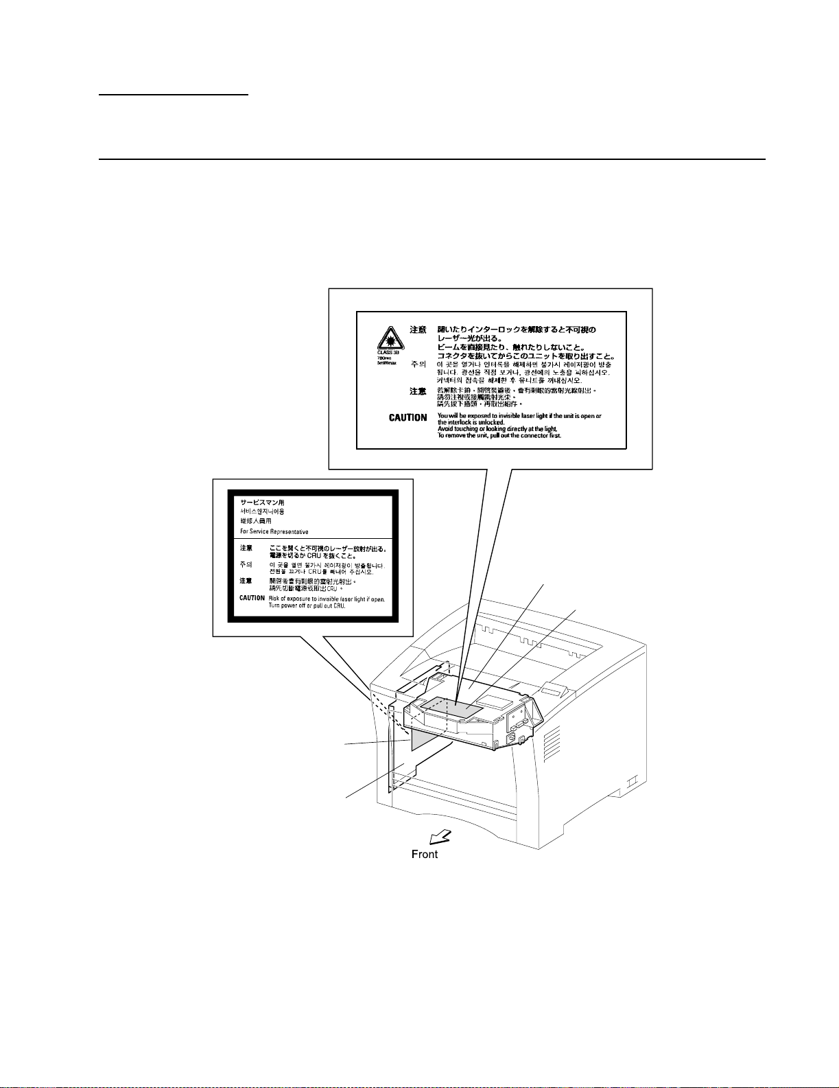
Laser Notices
Laser Adviso r y Lab el
Caution - Laser radiation when open. Avoid exposure to beam.
The following laser label may be affixed to this printer as shown.
Label
HVPS Cover
Printhead
Label
Laser Notices ix
Page 10
4022-XXX
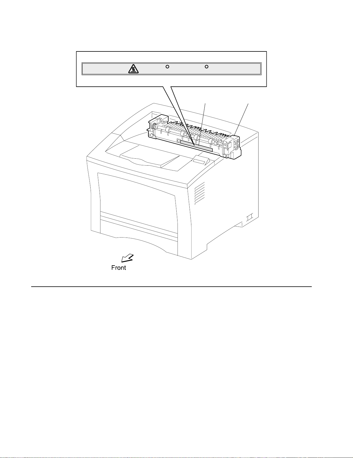
210 C/410 F
Label
Fuser Asm
Laser Not ice s
x Service Manual
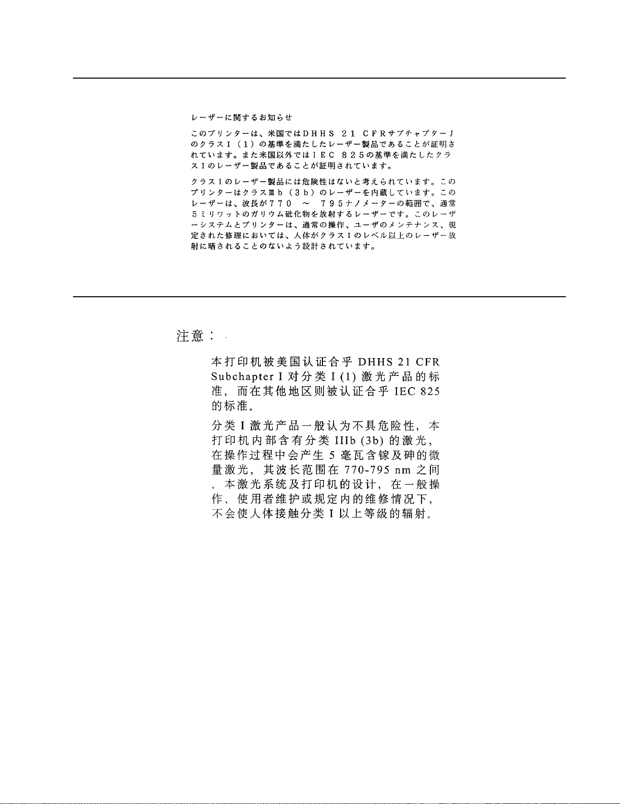
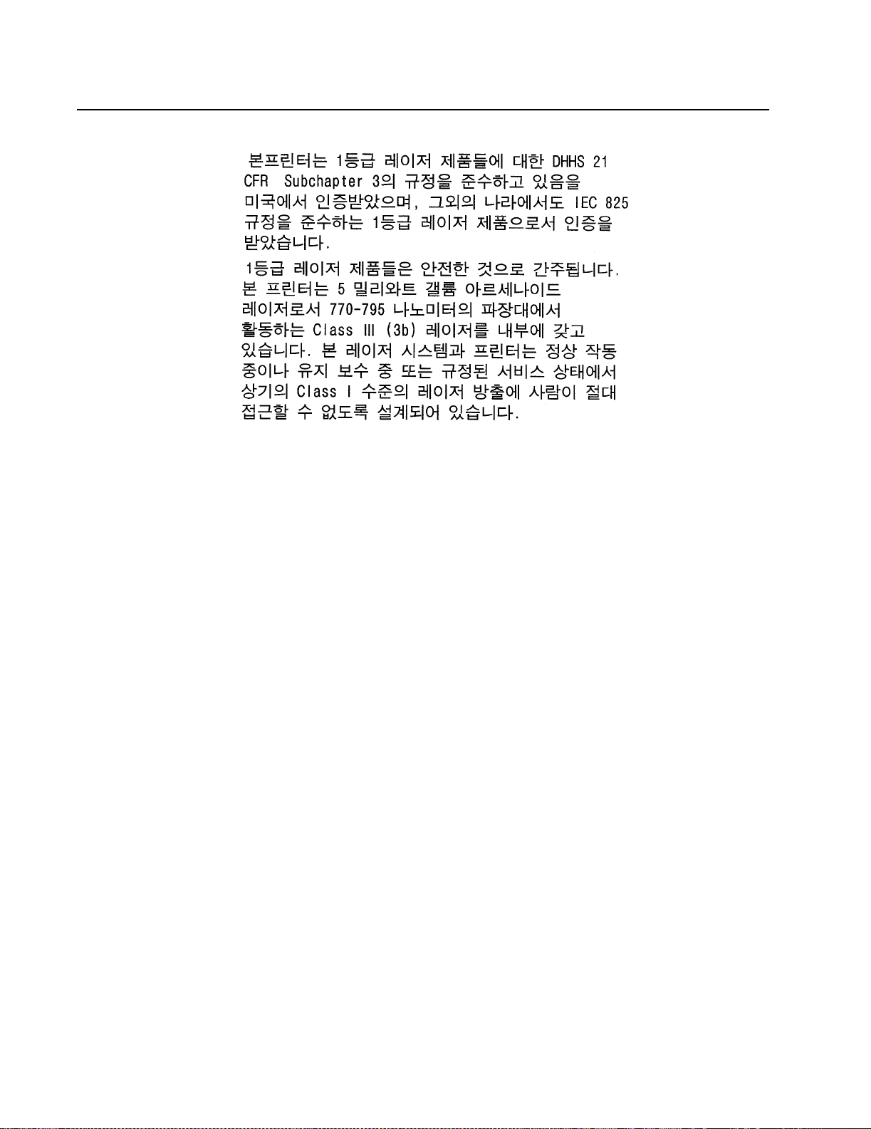
The printer is certified in the U.S. to conform to the requirements of DHHS 21 CFR
Subchapter J for Class I (1) laser products, and elsewhere is certified as a Class I laser
product conforming to the requirements of IEC 60825-1.
Class I laser products are not considered to be hazardous. The printer contains internally
a Class IIIb (3b) laser that is nominally a 5 milliwatt gallium arsenide laser operating in the
wavelength region of 770-795 nanometers. The laser syst em and printer are designed so
there is never any human access to laser radiation above a Class I level during normal
operation, user maintenance, or prescribed service condition.
Page 11

4022-XXX
Laser
Der Drucker erfüllt gemäß amtlicher Bestätigung der USA die Anforderungen der
Bestimmung DHHS (Department of Health and Human Se r v ices) 21 CFR Teil J für
Laserprodukte der Klasse I (1). In anderen Ländern gilt der Drucker als Laserprodukt der
Klasse I, der die Anforderungen der IEC (International Electrotechnical Commission)
60825-1 gemäß amtlicher Bestätigung erfüllt.
Laserprodukte der Klasse I gelten als unschädlich. Im Inneren des Druckers befindet sich
ein Laser der Klasse IIIb (3b), bei dem es sich um einen Galliumarsenlaser mit 5 Milliwatt
handelt, der Wellen der Länge 770-795 Nanometer ausstrahlt. Das Lasersystem und der
Drucker sind so konzipiert, daß im Normalbetrieb, bei der Wartung durch den Benutzer
oder bei ordnungsgemäßer Wartung durch den Kundendienst Laserbestrahlung, die die
Klasse I übersteigen würde, Menschen keinesfalls erreicht.
Avis relatif à l’utilisation de laser
Pour les Etats-Unis : cette imprimante est certifiée conforme aux provisions DHHS 21
CFR alinéa J concernant les produits laser de Classe I (1). Pour les autres pays : cette
imprimante répond aux normes IEC 60825-1 relatives aux produits laser de Classe I.
Les produits laser de Classe I sont considérés comme des produits non dangereux.
Cette imprimante est équipée d’un laser de Classe IIIb (3b) (arséniure de gallium d’une
puissance nominale de 5 milliwatts) émettant sur des longueurs d’onde comprises entre
770 et 795 nanomètres. L’imprimante et son système laser sont conçus pour impossible,
dans des conditions normales d’utilisation, d’entretien par l’utilisateur ou de révision,
l’exposition à des rayonnements laser supérieurs à des rayonnements de Classe I .
Laser Notices xi
Page 12

4022-XXX
Avvertenze sui prodotti laser
Questa stampante è certificata negli Stati Uniti per essere conforme ai requisiti del DHHS
21 CFR Sottocapitolo J per i prodotti laser di classe 1 ed è certificata negli altri Paesi
come prodotto laser di classe 1 conforme ai requisiti della norma CEI 60825-1.
I prodotti laser di classe non sono considerati pericolosi. La stampante contiene al suo
interno un laser di classe IIIb (3b) all’arseniuro di gallio della potenza di 5mW che opera
sulla lun gh ez z a d’onda compresa tra 770 e 795 nanometri. Il sistema laser e la
stampante sono stati progettati in modo tale che le persone a contatto con la stampante,
durante il normale funzionamento, le operazioni di servizio o quelle di assistenza tecnica,
non ricevano radiazioni laser superiori al livello della classe 1.
Avisos sobre el láser
Se certifica que, en los EE.UU., esta impresora cumple los requisitos para los productos
láser de Clase I (1) establecidos en el subcapítulo J de la norma CFR 21 del DHHS
(Departamento de Sa nidad y Ser vi cios ) y, en los demás países, reúne todas las
condiciones expuestas en la norma IEC 60825-1 para productos láser de Clase I (1).
Los productos láser de Clase I no se consideran peligrosos. La impresora contiene en su
interior un láser de Clase IIIb (3b) de arseniuro de galio de funcionamiento nominal a 5
milivatios en una longitud de onda de 770 a 795 nanómetros. El sistema láser y la
impresora están diseñados de forma que ningun a persona pueda verse afectada por
ningún tipo de radiación láser superior al nivel de la Clase I durante su uso normal, el
mantenimiento realizado por el usuario o cualquier otra situación de servicio técnico.
Declaração sobre La ser
A impressora está certificada nos E.U.A. em conformidade com os requisitos da
regulamentação DHHS 21 CFR Subcapítulo J para a Classe I (1) de produtos laser. Em
outros locais, está certificada como um produto laser da Classe I, em conformidade com
os requisitos da norma IEC 60825-1.
Os produtos laser da Classe I não são considerados perigosos. Internamente, a
impressora contém um produto laser da Classe IIIb (3b), designado laser de arseneto de
potássio, de 5 milliwatts ,operando numa faixa de comprimento de onda entre 770 e 795
nanómetros. O sistema e a impressora laser foram concebidos de forma a nunca existir
qualquer possiblidade de acesso humano a radiação laser superior a um nível de Classe
I durante a operação normal, a manutenção feita pelo utilizador ou condições de
assistência pr escritas.
xii Service Manual
Page 13

4022-XXX
Laserinformatie
De printer voldoet aan de eisen die gesteld worden aan een laserprodukt van klasse I.
Voor de Verenigde Staten zijn deze eisen vastgelegd in DHHS 21 CFR Subchapter J,
voor andere landen in IEC 60825-1.
Laserprodukten van klasse I worden niet als ongevaarlijk aangemerkt. De printer is
voorzien van een laser van klasse IIIb (3b), dat wil zeggen een gallium arsenide-laser van
5 milliwatt met een golflengte van 770-795 nanometer. Het lasergedeelte en de printer
zijn zo ontworpen dat bij normaal gebruik , bij onderhoud of reparatie conform de
voorschriften, nooit blootstelling mogelijk is aan laserstraling boven een niveau zoals
voorgeschrev en is voor klasse 1.
Lasermeddelelse
Printeren er godkendt som et Klasse I-laserprodukt, i overenstemmelse med kravene i
IEC 60825 -1 .
Klasse I-laserprodukter betragtes ikke som farlige. Printeren indeholder internt en Klasse
IIIB (3b)- las e r, der nom ine lt er en 5 milli watt ga lliumars e nid las e r, som ar b ejd er på
bølgelængdeområdet 770-795 nanom eter. Lasersystemet og printeren er udformet
således, at mennesker aldrig udsættes for en laserstråling over Klasse I-niveau ved
normal drift, brugervedligeholdelse eller obligatoriske servicebetingelser.
Huomautu s las er laittees ta
Tämä kirjoitin on Yhdysvalloissa luokan I (1) l aserlaitteiden DHHS 21 CFR Subchapter J määrityksen mukainen ja muualla luokan I laserlaitteiden IEC 60825-1 -määrityksen
mukainen.
Luokan I laserlaitteiden ei katsota olevan vaar allisia käyttäjälle . Kir joittimessa on sisäinen
luokan IIIb (3b) 5 milliwatin gallium ar se nidil as er, joka toimii aaltoaluee lla 770 - 79 5
nanometriä. Laserjärjestelmä ja kirjoitin on suunniteltu siten, että käyttäjä ei altistu luokan
I määrityksiä voimakkaammalle säteilylle kirjoittimen normaalin toiminnan, käyttäjän
tekemien huoltotoimien tai muiden huoltotoimien yhteydessä.
VARO! Avattaessa ja suojalukitus ohitettaessa olet alttiina näkymättömälle
lasersäteilylle. Älä katso säteeseen.
VARNING! Osynlig laserst r ålning när denna del är öppnad och spärren är urkopplad.
Betra k ta e j s trålen.
Laser Notices xiii
Page 14

4022-XXX
Laser-notis
Laser-melding
Denna skrivare är i USA certifierad att motsvara kraven i DHHS 21 CFR, underparagraf J
för laserprodukter av Klass I (1). I andra länder uppfyller skrivaren kraven för
laserprodukter av Klass I enligt kraven i IEC 60825-1.
Laserprodukter i Klass I anses ej hälsovådliga. Skrivaren har en inbyggd laser av Klass
IIIb (3b) som består av en laserenhet av gallium-arsenid på 5 milliwatt som arbetar i
våglängdsområdet 770-795 nanometer. Lasersystemet och skrivaren är utformade så att
det aldrig finns risk för att någon person utsätts för laserstrålning över Klass I-nivå vid
normal användning, underhåll som utförs av användaren eller annan föreskriven
serviceåtgärd.
Skriveren er godkjent i USA etter kravene i DHHS 21 CFR, underkapittel J, for klasse I (1)
laserprodukter, og er i andre land godkjent som et Klasse I-laserprodukt i samsvar med
kravene i IEC 60825-1.
Klasse I-laserprodukte r er ik ke å betrakte som farlige. Skriveren inneholder internt en
klasse IIIb (3b)-laser, som består av en gallium-arsenlaserenhet som avgir stråling i
bølgelengdeområdet 770-795 nanometer. Lasersystemet og skriveren er utformet slik at
personer aldri utsettes for laserstråling ut ov er klasse I-nivå under vanlig bruk, vedlikehold
som utføres av brukeren, eller foreskrevne serviceoperasjoner.
Avís sobre el Làser
Segons ha estat certificat als Estats Units, aquesta impressora compleix els requisits de
DHHS 21 CFR, apartat J, pels productes làser de classe I (1), i segons ha estat certificat
en altres llocs, és un producte làser de classe I que compleix els requisits d’IEC 60825-1.
Els productes làser de classe I no es consideren perillosos. Aquesta impressora conté un
làser de classe IIIb (3b) d’arseniür de gal.li, nominalment de 5 mil.liwats, i funciona a la
regió de longitud d’ona de 770-795 nanòmetres. El sistema làser i la impressora han
sigut concebuts de manera que mai hi hagi exposició a la radiació làser per sobre d’un
nivell de classe I durant una operació normal, durant les tasques de manteniment
d’usuari ni durant els serveis que satisfacin les condicions prescrites.
xiv Service Manual
Page 15
4022-XXX
Japanese Laser Notice
Chinese Las er Notice
Laser Notices xv
Page 16
4022-XXX
Korean Laser Notice
xvi Service Manual
Page 17

4022-XXX
Safety Information
• The safety of this product is based on testing and approvals of the original design
and specific components. The manufacturer is not responsible for saf ety in the e v ent
of use of unauthorized replacement parts.
• The maintenance information for this product has been prepared for use by a
professional service person and is not intended to be used by others.
• The re may be an increased risk of electric shock and personal injury duri ng
disassembly and servicing of this product. Professional service personnel should
understand this and take necessary precautions.
Consignes de Sécurité
• La sécurité de ce produit repose sur des tests et des
agréations portant sur sa conception d'origi ne et sur des composant s particuliers.
Le fabricant n'assume aucune responsabilité concernant la sécurité en cas
d'utilisat io n d e p ièc es de rec hange non agréées.
• Les consignes d'entretien et de réparation de ce produit s'adressent uniquement à
un personnel de maintenance qualifié.
• Le dém ont age et l'entretien de ce produit pouvant présenter certains risques
électriques, le personnel d'entretien qualifié devra prendre toutes les précautions
nécessaires.
Norme di sicurezza
• La sicurezza del prodotto si basa sui test e sull'approvazione del progetto originale e
dei componenti specifici. Il produttore non è responsabile per la sicurezza in caso di
sostituzione non autorizzata delle parti.
• Le informazioni riguardanti la manutenzione di questo prodotto sono indirizzate
soltanto al personale di assistenza autorizzato.
• Durante lo smonta ggio e la manutenzione di questo prodotto,
il rischio di subire scosse elettriche e danni alla persona è più elevato. Il personale di
assistenza autorizzato, deve, quindi, adottare le precauzioni necessarie.
Sicherheitshinweise
• Die Sicherheit dieses Produ kts bas ier t auf Tests und Zulassungen des
ursprünglichen Modells und bestimmter Bauteile. Bei Verwendung nicht
genehmigter Ersatzteile wird vom Hersteller keine Verantwortung oder Haftung für
die Sicherheit übernommen.
• Die Wartungs inform ationen für dieses Produkt sind ausschließlich für die
Verwendung durch einen Wartungsfachmann bestimmt.
• Während des Auseinandernehmens und der Wartung des Geräts besteht ein
zusätzliches Risiko eines elektrischen Schlags und körperlicher Verletzung. Das
zuständige Fachpersonal sollte entsprechende Vorsichtsmaßnahmen treffen.
Safety In fo rma tion xvii
Page 18

4022-XXX
Pautas de Segu ridad
• La seguri dad de es te producto se basa en pru ebas y aproba ciones del diseño
original y componentes específicos. El fabricante no es responsable de la
seguridad en caso de uso de piezas de repuesto no autorizadas.
• La información sobre el mantenimiento de este producto está dirigida
exclusivamente al personal cualificado de mantenimiento.
• E xiste mayor riesgo de descarga eléctrica y de daños personales durante el
desmontaje y la reparación de la máquina. El personal cualificado debe ser
consciente de este peligro y tomar las precauciones necesarias.
Informações de Segurança
• A segurança deste produto baseia-se em testes e aprovações do modelo original e
de componentes específicos. O fabricante não é responsável pela segunrança, no
caso de uso de peças de su bstituição não autorizadas.
• As informações de segurança relativas a este produto destinam-se a profissionais
destes serviços e não devem ser utilizadas por outras pessoas.
• Risco de choques eléctricos e ferimentos graves durante a desmontagem e
manutenção deste produto. Os profissionais destes serviços devem estar avisados
deste facto e tomar os cuidados necessários.
Informació de Seguretat
• La seguret at d'aque st producte es basa en l'avaluació i aprovació del disseny
original i els components específics.
El fabricant no es fa responsable de les qüestions de
seguretat si s'utilitzen peces de recanvi no autoritzades.
• La informació pel manteniment d’aquest producte està orientada exclusivament a
professionals i no està destinada
a ningú que no ho sigui.
• El risc de xoc elèctric i de danys personals pot augmentar durant el procés de
desmuntatge i de servei d’aquest producte. El personal professional ha d’estar-ne
assabentat i prendre
les mesures convenients.
xviii Ser v ice M anual
Page 19
4022-XXX
Safe ty In formation xix
Page 20

4022-XXX
Preface
This manual contains maintenance procedures for service personnel only . It is divided
into the following chapters:
1. General Informa tion contains a general description of the printer and the
maintenance approach used to repair it. Special tools and test equipment are listed
in this chapter, as well as general environmental and safety instructions.
2. Diagnostic Information contains an error indicator table, symptom tables, and
service checks used to isolate failing field replaceable units (FRUs).
3. Diagnostic Aids contains tests and checks used to locate or repeat symptoms of
printer problems.
4. Re pair I nformation provides instructions for making printer adjustments and
removing and installing FRUs.
5. Connector Locations uses illustrations to identify the connector locations and test
points on the printer.
6. Prev enti ve Maintena nce contains the lubrication specifications and
recommendations to prevent problems.
7. Parts Catalog contains illustrations and part numbers for individual FRUs.
xx Service Manual
Page 21

4022-XXX
1. General Information
The Lexmark™ W812 printe r is a mid-range mono laser printer available in two models:
• 4022-10 0 is a base model of the W812 with 16MB of standard memor y and US B/
parallel port connectors.
• 4022-110 is a network model of the W812 with 32 MB of standard memory and USB/
Ethernet 10BaseT/100 BaseT X network port connectors.
Product features include:
• A3 support
• 26 ppm
• Me mory expandable up to an additional 256MB
• Optional 250-sheet drawer
• Optional 500-sheet drawer
• Optional Unit
The product supports the following operating systems:
• Wind ows 95/98/Me
• Wind ows NT 4.0
• Wind ows 2000
• Wind ows XP
• Macintosh OS 8.6-9.x
• Macintosh OS X (10.1.2)
• UNIX/Linus
Maintenance Approach
The diagnostic information in this manual leads you to the correct field replaceable unit
(FRU) or part. Use the service error codes, user status messages, user error message,
service checks, and diagnostic aids to determine the printer problem and repair the
failure. After you complete the repair, perform tests as needed to verify the repair.
Tools Required
The removal and replacement procedures described in this manual require the following
tools and equipment:
• Flat-blade screwdriver
• #1 Phillips scr ewdriver
• #2 Phillips scr ewdriver
• Needl enose pliers
• Diago nal pliers
• Spring hook
• A nalog or digital multimeter
General Information 1-1
Page 22

4022-XXX
Acronyms
BCR Bias Charge Roll
CM Charging and Metering
CSU Customer Setu p
DIMM Dual Inline Memory Module
DRAM Dynamic Random Access Memor y
EDO Enhanced Data Out
EP Electrophotographic Process
EPROM Erasable Programmable Read-Only Memory
ESD Ele ctrostatic Discharge
FG Frame Ground
FRU Field Replaceable Unit
GB Gigabyte
HVPS High Voltage Power Supply
LASER Light Amplification by Stimulated Emission of Radiation
LCD Liquid Crystal Display
LD Laser Diod e
LED L ight-Emitting Diode
LVPS Low Voltage Power Supply
MROM Masked Read Only Memor y
NVR AM Nonvo latile Random A ccess Mem or y
OEM Original Equipment Manufacturer
PC Photoconductor
POR Power-On Reset
POST Power-On Self Test
RIP Raster Imaging Processor
ROM Read-Only Memory
SDRAM Synchronous Dynamic Random Access Memory
SRAM Static Random Access Memory
UPR Used Parts Return
V ac Volts alternating current
V dc Volts direct current
TTL Transistor-Transistor Logic
1-2 Service Manual
Page 23
4022-XXX
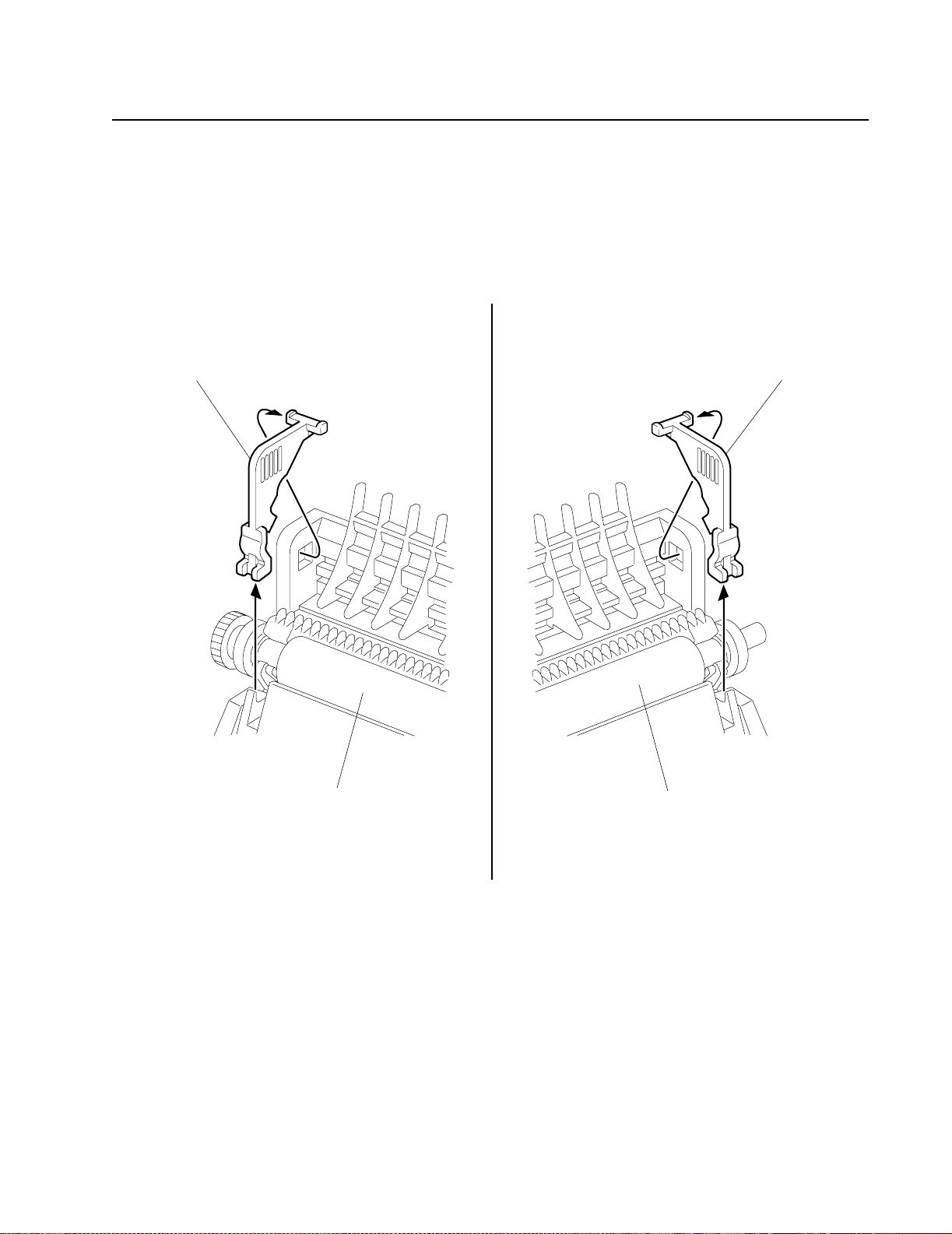
Preparing for shipping
When a printer is first installed, two transfer roll stops (bright orange in color) are removed
before the toner cartridge can be installed. These transfer roll stops prevent roll from
coming loose during shipping.
Whenever the printer is to be shipped, reinstall the stops.
Transfer Roll Stop
Left
Right
Transfer Roll Stop
Transfer Roll Assembly Transfer Roll Assembly
General Information 1-3
Page 24
4022-XXX
Principl es of Oper at io n
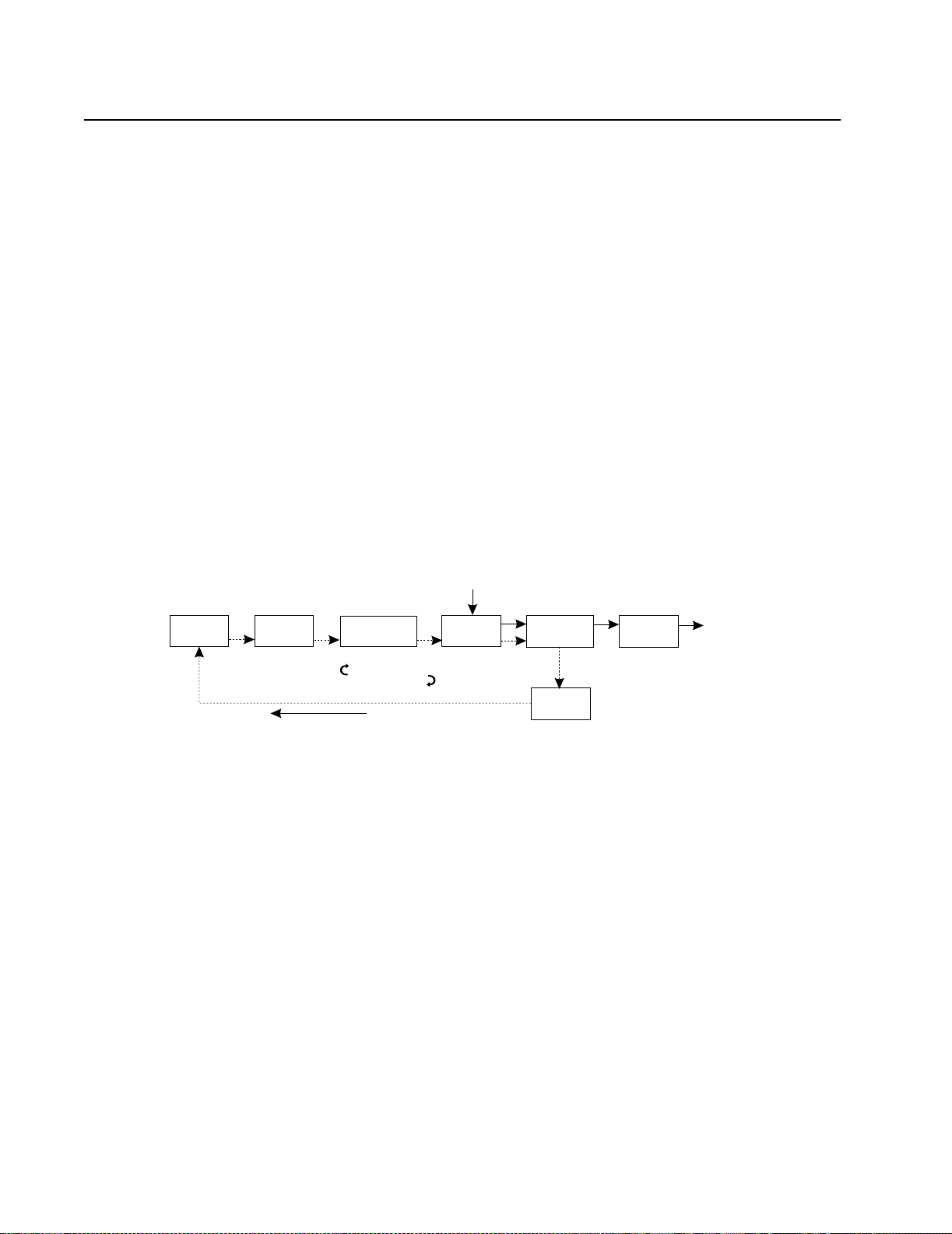
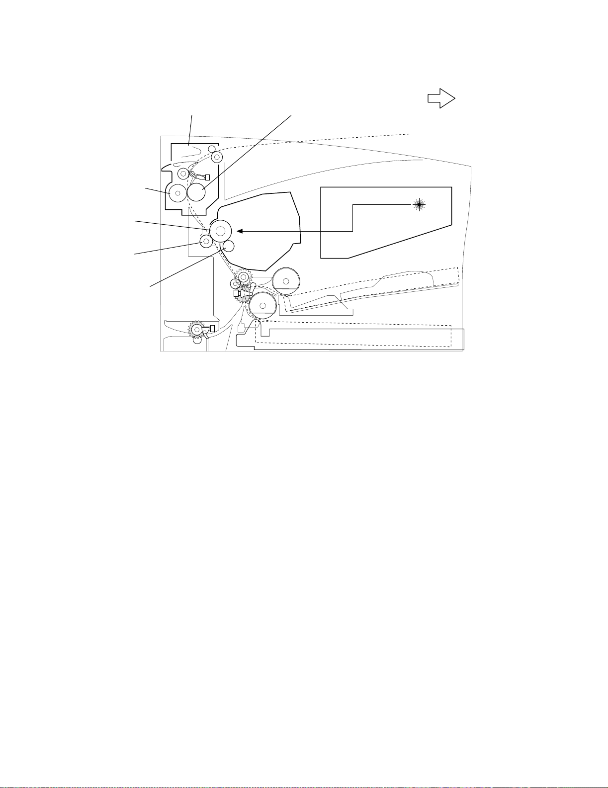
Overview of Print Process
The printer provides a electrophotographic process function to print image on paper with
video signals sent from the controller board to the engine board. The electrophotographic
process consists of the following seven steps.
1. Charge - Equally assigns negative charge on the drum surface by the bias charge
roll.
2. Exposure - The laser scanner scans the drum surface and generates an invisible
electrostatic latent image on the drum surface using super-fine laser beams
modulated according to signals sent from the controller.
3. Development - Draws toner toward an electrostatic latent image on the drum
surface and creates a visible toner image.
4. Transcription - Transcribes a toner image from the dr um surface to paper.
5. Exfoliation - Cast off paper from the drum surface by partially neutralizing charge on
paper.
6. Fusing - Permanently fuses a toner image by heat and pressure.
7. Cleaning - Eliminates the remaining toner from the drum surface.
1. Charge
Paper Enters
2. Exposure
3. Development
Xerographic cycle
Cycle repeats for the next print
4. Transfer
5. Detack
7. Cleaning
6. Fusing
Paper Exits
Rotating the drum, the drum surface passes six steps (charge, exposure, development,
transcription, exfoliation, and cleaning), creates a toner image, and transcribes the
created image on paper. Paper passes three steps (transcription, exfoliation, and fusing)
by the paper transfer mechanism. When paper is positioned as shown in image, toner
image is transcribed from the drum surface to paper, and then fused.
1-4 Service Manual
Page 25
4022-XXX
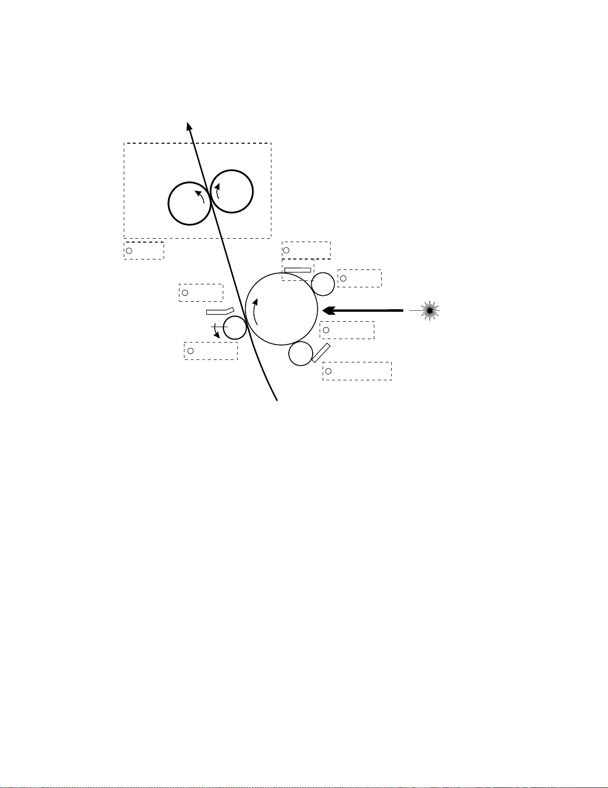
The illustrations show the major components directly related to the print process and
paper transfer.
Back-up
Roll
6
FUSING
Detack Saw
Transfer Roller
5
DETACK
4
TRANSFER
Hot Roll
Cleaning
Blade
7
Drum
Mag.Roll
Paper
CLEANING
BCR
1
CHARGE
2
EXPOSURE
CM Blade
3
DEVELOPMENT
Laser Beam
General Information 1-5
Page 26
4022-XXX
Pressure
Roll
Drum
Transfer
Roller
Mag. Roll
Fuser Assembly Heat Roll
Toner
Cartridge
Front
Printhead
1-6 Service Manual
Page 27

4022-XXX
In the exposure step, thin laser beam scans the drum surface which was negatively
charged in the charging step of the previous process. The laser beam emitted by the laser
diode of the printhead scans from end to end of the drum through the rotating polyhedron
mirror (Polygon Mirror: 6 or 12 sides) and lens.
Radiation from the laser beam is adjusted according to the video signal from the
controller.
The laser beam irradiated to the drum excites the electron going toward the conductor
and generates a pair of electronic holes in the light transmission layer. As the electronic
holes move to the surface of the light transmission layer when the electron moves toward
the body in the drum along the electric field, the negative charge at that part decreases
and invisible electrostatic latent image is generated.
Toner is absorbed to the electrostatic latent image and developed.
Toner absorbe d to the drum is attracted by the positive electric charge supplied by
Transfer Roller and transcribed on the paper and the drum goes to the separating and
cleaning process.
In the cleaning step, residual toner is removed from the drum surface as the surface is
prepared for the next cycle.
The toner is scraped off the drum surface by the cleaning blade.
Note: The toner rubbed off in the cleaning step is collected in the recovery toner
compartment separated from the unused toner. The transcription ratio is 90% or more,
but it varies depending on the image cover range and environment conditions such as the
temperature and humidity. The used toner cannot be reused.
Note: At the starting time for each print process, the entire drum surface is scanned with
laser beams, and the charge remaining on the drum surface from the preceding print step
is remo ved complete ly.
Note: At the starting and ending times of the continuous print process, the negative highvoltage is applied to the Transfer Roller. If residual toner is on the Transfer Roller surface
in the preceding print step, it is returned onto the drum surface to clean the Transfer
Roller surface.
General Information 1-7
Page 28
4022-XXX
Paper Transfer
Paper is supplied from tray 1 or chute MPF, and carried to the printer along the paper
route shown in the illustration.
The optional duplex assembly has an individual motor (bracket assembly motor duplex) to
transfer paper.
Tray 1
Roll Assembly Tray 1
Roll Pinch Registration (lower)
Roll Pinch Registration (upper)
Chute Assembly Transfer
MPF
Roll Assembly MPF
Roll Registration Metal
Roll Registration Rubber
Transfer Roller
Drum
Toner Cartridge
Fuser Assembly
1-8 Service Manual
Heat Roll
Pressure Roll
Roll Assembly Decurler
Roll Pinch
Roll Assembly Exit
Roll Pinch
Page 29
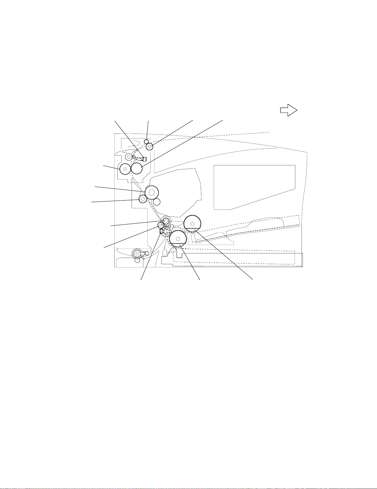
4022-XXX
The illustration below shows the major components directly related to the paper route and
paper transfer. See "Options" for the major components related to the paper route and
paper transfer when the optional devices (Tray 2, Tray 3, and Duplex) are attached to the
printer.
Exit Sensor
Pressure
Roll
Drum
Transfer
Roller
Roll
Registration
Metal
Roll
Registration
Rubber
Roll Pinch Exit
Sensor
Registration
Exit Roll
Roll Assembly
Tray 1
Heat Roll
Front
Roll Assembly MPF
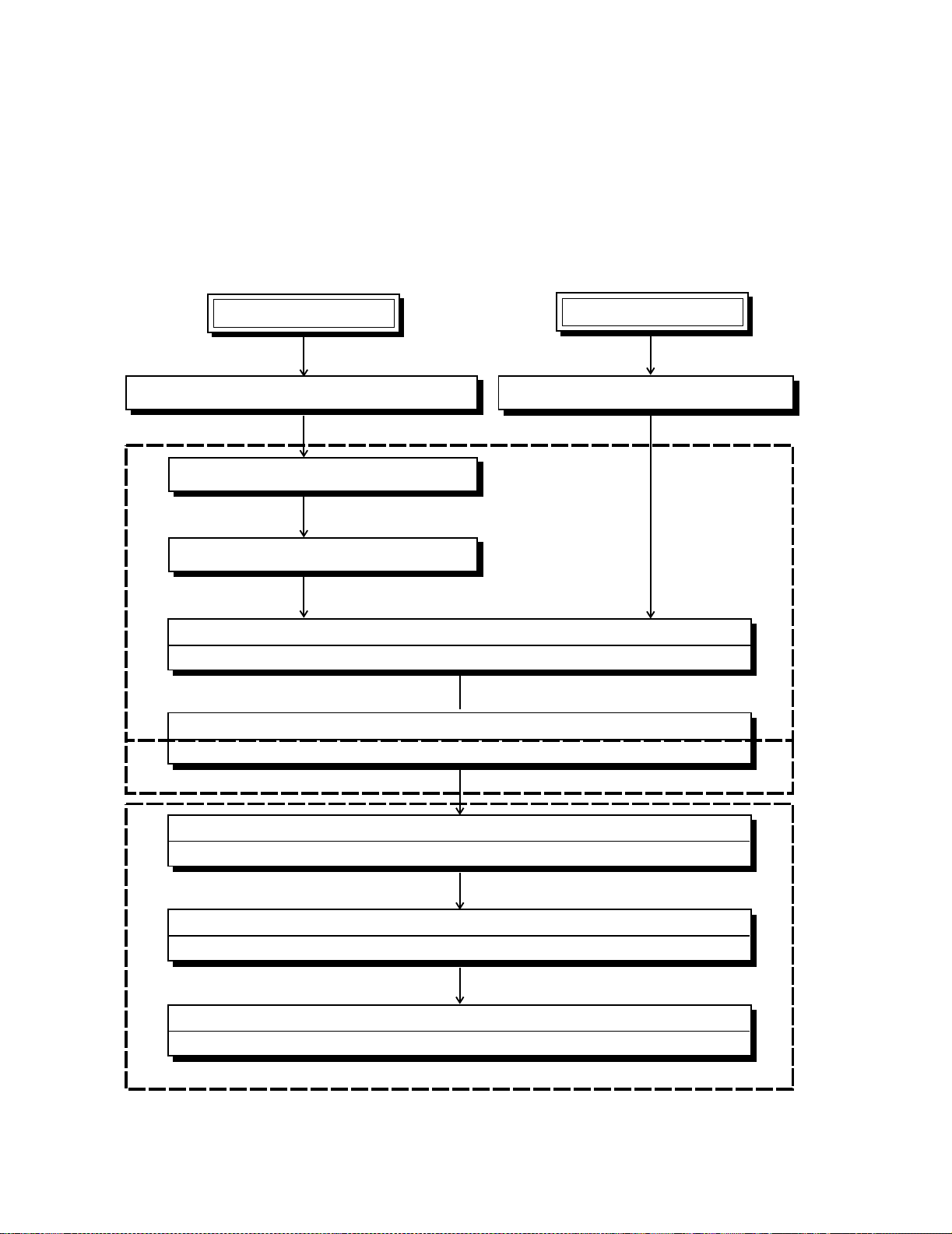
Generating Print Image
The printers attached to the network, the network interface card (NIC) of the printer
connected to network receives packet signals from a network client or server in a bit
stream, and decomposes the received packet signals into a data format for the layer
where data is sent to the controller. The controller processes the data sent from the NIC
in the same way as of the data received from the host computer through a parallel port.
Data received from the NIC or parallel port is called host data.
The controller board buffers host data in the lustered bit image or converts host data of
the page description language (PDL) into the lustered bit image data. The controller
board sends the lustered bit image data to the engine board line by line each time laser
beams are scanned.
The signal that transfers image data (/VDO signal) is converted into an LVDS signal by
the engine board, and sent to the printhead as a P.DATA+P.DATA signal. The printhead
General Information 1-9
Page 30

4022-XXX
converts the signal into laser beams, and radiated as super fine laser beams. The laser
beams are turned on and off according to a video signal. Laser beams, that are emitted
from the surface of the rotating polygon mirror, are collectively irradiated on the drum
surface of the EP cartridge. An electrostatic latent image is then generated on the drum
surface.
Transmissi on of Driving Power
The driving power is generated by the Motor Assembly (component of the Main Drive
Assembly), and transferred to the printer components, that requires the mechanical
driving power, through the gear and gear train in the Main Drive Assembly.
As shown in the following illustrations, the driving power is distributed to the toner
cartridge, chute assembly transfer, Roll Assembly MPF, Roll assembly tray 1, optional
feeder, and fuser assembly through the gear in the drive assembly.
The driving power transmitted to the chute assembly transfer drives the roll registration
metal and roll registration rubber. The driving power transmitted to the toner cartridge
drives the drum, and it is t ransmitted t o t he Transfer Rol ler of the chute assembly transf er.
The driving power transmitted to the fuser assembly drives the heat roll, and it is further
transmitted to the roll assembly exit by the gear decurler.
1-10 Service Manual
Page 31

4022-XXX
Motor Assembly
Gear 2
Gear 3
Gear 4
Drum Gear
(EP Cartridge)
Transfer Roller
Gear 15
Gear 16
Clutch Registration
Gear Clutch
Gear Registration
(Roll Registration
Rubber)
Gear Registration
Rubber
Gear Registration
Metal
Chute Asm Transfer
Gear 10
Gear 11
Gear 12
Gear 13
Gear 14
Gear 40
Gear 40
Pick Up T1
Gear 23 MSI
Gear 40
Pick Up MSI
Gear 5
Clutch Turn
/Gear Turn
(Roll Asm Turn
/Shaft Turn 14)
Gear 24 Turn R
(to Feeder Asm Opt)
Gear 6
Gear 7
Gear 8
Gear 9
Main Drive Assembly
Gear IDL HR
Gear HR
Gear Decurler
Clutch Assembly
Spring
Gear Idler
Gear Exit
Fuser Assembly
General Information 1-11
Page 32

4022-XXX
(
Gear Idler
Dup In
Gear
Decurler
Gear HR
Gear IDL
HR
Gear 9
Gear 8
Gear 7
Gear 6
Motor
Asembly
Gear 5
Gear 10
Gear 11
Drive
Assembly
Clutch Asm
Spring
Clutch Turn
/Gear Turn
(Roll Asm Turn
/Shaft Turn 14)
Gear 24 Turn R
to Feeder Asm Opt)
Gear Idler
Gear 12
Gear 13
Gear 15
Gear Exit
Fuser Assembly
Gear 16 Gear 14
Drum Gear
(EP Cartridge)
Gear Clutch
Clutch
Registration
Front
Gear 4
Gear 3
Gear 2
Gear 23 MPF
Gear 40 Pick Up
MPF
Gear 40
Gear 40 Pick Up
T1
Gear Registration
(Roll Registration Rubber)
Gear Registration Rubber
1-12 Service Manual
Page 33

4022-XXX
Driving Power Tran smission to Paper Feeder
The driving power generated by the motor assembly is transmitted from the gear 14 of the
main drive assembly to the roll assembly MPF and roll assembly tray 1 via the gear 40.
Each time the solenoid MPF or solenoid T1 functions, the gear 40 pick up MPF or
solenoid T1 is pulled by the spring pick up or spring pick up T1, and rotates by one turn,
engaging with gear 14 in the gear 23 MPF or main drive assembly. After one turn ends,
the system releases the engagement with the gear 14 in the gear 23 MPF or main drive
assembly. When the roll assembly MPF or tray 1 driven by the gear 40 pick up MPF or
solenoid T1 rotates by one turn, a sheet of paper is supplied from the tray assembly MPF
or cassette assembly 250 to the printer.
Front
Motor
Assembly
Gear 5
Gear 10
Gear 11
Drive
Assembly
Gear 12 Gear 13
Gear 14
Gear 40
Gear 40 Pick Up T1
Gear 23 MPF
Gear 40
Pick Up MPF
General Information 1-13
Page 34

4022-XXX
Drivi ng P o wer Transmissi on to Ro ll Regis trati on Met al and Rubber
The driving power generated by the motor assembly is transmitted from gear 16 to the
clutch registration in the main drive assembly.
When the clutch registration functions, the driving power is transmitted to the gear
registration by the gear clutch to drive the roll registration rubber. The driving power is
then transmitted from the right gear registration rubber of the roll registration rubber to the
gear registration metal to drive the roll registration metal.
Front
Motor
Assembly
Gear 5
Gear 10
Gear 11
Drive
Assembly
Gear 12 Gear 13
Gear 14
Gear 40
Gear 40 Pick Up T1
Gear 23 MPF
Gear 40
Pick Up MPF
1-14 Service Manual
Page 35

4022-XXX
Drum Gear
(EP Cartridge)
Driving Power Transmission to Drum and Transfer Roller
The driving power generated by the motor assembly is transmitted from gear 4 of the
main drive assembly to the drum of the toner cartridge.
The driving power is then transmitted from the drum to the Transfer Roller. The
connection of the shaft of gear 4 (that transmits the driving power) with the drum is
controlled by the cover open cam driven by opening and closing the top cover. The driving
power is not transmitted to the toner cartr idge unless the top cover is closed.
Front
Gear 4
Transfer
Roller
Gear 3
Gear 2
Motor
Assembly
Main Drive
Assembly
General Information 1-15
Page 36

4022-XXX
y
Driving Power Transmission to Fus er Assembly
The driving power generated by the motor assembly is transmitted from gear 9 of the
main drive assembly to the fuser assembly.
The connection of gear 8 and gear 9 (that transmit the driving power) with the fuser
assembly is controlled by the cover open cam driven by opening and closing the top
cover. The driving power is transmitted only when the top cover is closed.
Gear Idler
Dup In
Gear
Decurler
Gear HR
Gear IDL
HR
Gear 9
Gear 8
Gear 7
Gear 6
Motor
Assembly
Gear 5
Main Drive
Assembl
Clutch
Assembly
Spring
Gear
Idler
Front
Gear Exit
Fuser Assembly
1-16 Service Manual
Page 37

4022-XXX
Driving Power Transmission to Roll Assembly
The driving power generated by the motor assembly is transmitted from gear 11 of the
main drive assembly to the clutch turn, The driving power drives the duplex output feed
roll reinserted to print the second side of paper transferred from the duplex assembly.
The driving power is then transmitted to the feeder assembly option 250 or feeder
assembly 500 by gear 24 turn R attached to the right of the duplex output feed roll or shaft
turn 14.
Front
Motor
Assembly
Gear 5
Gear 10
Gear 11
Main Drive
Assembly
Clutch Turn
(Duplex Output Feed Roll
/Shaft Turn 14)
Gear 24 Turn R
(to Feeder Assembly Option)
Printer Component Function
250-Sheet Paper Tray/Cassette Assembly
Guide Paper Left, Guide Paper Right - Adjusts to the left and right to fit to different paper
sizes. These components hold paper at the specified positions on the left and right
respectively.
General Information 1-17
Page 38

4022-XXX
Guide End - Adjusts forward and backward to fit to different paper sizes. These
components hold paper at the specified positions forward and backward respectively.
The size of paper in the cassette must be transmitted to the printer control unit as a set
value by the dial paper size.
Plate Lift L Plate Lift R - Mounted at the end of the cassette, the plate lifts are pushed up
when the cassette is inserted into the printer.
Lift Plate - The force for pushing up the lift plate is supplied by the springs connected to
the plate lift. Pushing up the lift plate assures the contact between the supplied paper and
pick rolls.
Separator Pad - Applies the friction force to the lower side of paper preventing multiple
sheets from being picked simultaneously by the pick roll. This component is to be
replaced each 100,000 sheets.
Guide Paper L
Front
Plate Lift L
Guide End
Paper Tray/Cassette
Assembly
Lift Plate
Lift Plate
Separator Pad
Plate Lift R
Guide Paper R
Plate Lift
L and R
Front
1-18 Service Manual
Page 39

4022-XXX
Paper Pick/Feed
Tray Present Switch - When the 250 sheet paper tray is inserted to the specified position,
the end of the tray presses the tray present switch, and the printer recognizes the tray is
inserted.
Tray 1 Empty Flag - When sheets of paper in the 250 sheet paper tray are used up, the
end of the tray 1 empty flag drops in the opening of the lift plate, and the flag shades the
tray empty sensor.
Tray 1 Empty Sensor - Senses whether paper is set in the 250 sheet paper tray at the
position of the tray 1 empty flag, and converts the sensing result into an electric signal.
When the sensor receives the light, the NO PAPER1 signal (paper setting state) is set
low.
MPF Empty Flag - When sheets of paper are used up in the MPF tray, the end of the
drops in the opening in the center of the MPF tray, and the flag shades the sensor.
MPF Empty Sensor - Senses whether paper is set in the MPF tray at the position of the
MPF actuator, and converts the sensing result into an electric signal. When the sensor
receives the light, the NO PAPER MPF signal (paper setting state) is set low.
MPF Separator Pad - Applies the friction force to the lower side of paper and prevents
multiple sheets from being picked simultaneously . This component is to be replaced each
time 100,000 sheets are printed.
Tray 1 Pick Roll - Supplies paper from the 250-paper tray to the printer. The rotation is
always stopped by the tray 1 solenoid; however, when the solenoid is energized, this unit
turns once to supply paper. The pick roll is to be replaced each time 100,000 sheets are
printed.
MPF Pick Roll - Supplies paper from the MPF tray to the printer. The rotation is always
stopped by the MPF solenoid; however, when the solenoid is energized, this unit turns
once to supply paper. The pick roll is to be replaced each time 100,000 sheets are
printed.
General Information 1-19
Page 40

4022-XXX
MPF Pick Roll
MPF Separator
Flag
MPF Empty
Flag
MPF Empty
Sensor
Tray 1 Empty
Sensor
Tray 1 Pick Roll
Tray Present
Switch
Tray 1 Empty Flag
Front
1-20 Service Manual
Page 41

4022-XXX
l
Front
MPF Empty Flag
MPF Empty
Sensor
MPF Pick Roll
Tray 1
Pick Rol
Tray 1
Present
Switch
Tray 1
Empty
Tray 1
Empty Flag
Sensor
Optional Feeder Drive Gear - Transmits the driving power generated by the main drive
assembly to the optional 250- or 500-sheet optional feeder.
Duplex Output Feed Roll Clutch - Determines a timing for supplying paper from the
duplex assembly to the lower paper guide assembly . When paper is supplied from the
optional feeder, this clutch is also energized, and the driving power is transmitted to the
optional feeder.
Duplex Output Feed Roll Assembly - The driving power is transmitted to this unit by
energizing the duplex output feed roll clutch, and this unit transf ers paper from the duple x
assembly to the lower paper guide assembly.
Duplex Output Sensor Flag - An actuator sensing that paper is present at the duplex
output feed roll assembly.
Duplex Output Sensor - Senses whether paper is present at the duplex output feed roll
assembly.
General Information 1-21
Page 42

4022-XXX
Front
Duplex Output
Feed Roll Clutch
Duplex Output
Sensor
Duplex Output
Sensor Flag
Transfer Roller the drum of the toner cartridge.
The Transfer Roller applies the positive charge onto the back of paper when paper moves
between the Transfer Roller and drum. A negatively charged toner image is drawn by the
positive charge on the backside of paper, and transcribed from the drum surface to the
paper face.
Metal and Rubber Registration - Roll rotation is controlled by the registration roller clutch,
and paper is positioned with an image of the drum surface.
Detack Blade - Applies the negative charge to the back of paper to partially neutralize the
positive charge, and cast off paper from the drum surface.
Varistor - Installed between the frame and Transfer Roller, this component helps reduce
noise that can alter the voltage level on the Transfer Roller.
Toner Low Sensor - Residual toner in the toner cartridge is measured with the
electromagnetic sensor and a warning for replacement is issued (optional).
The Transfer Roller is driven by the drum gear, coming into contact with
Duplex Output
Feed Roll Assembly
1-22 Service Manual
Page 43

4022-XXX
Detack Blade
Rubber
Registration
Roll
Transfer
Roller
Varistor
Metal
Registration
Roll
Front
Registration
Sensor Flag
Registration
Sensor
Registration
Sensor
Flag
Registration
Sensor
General Information 1-23
Page 44

4022-XXX
Toner Low Sensor
Front
Fuser
The fuser assembly contains a fusing component and a component for ejecting printed
paper from the printer. It also has a function that reverse-inserts paper to the duplex
assembly when the optional duplex assembly is attached to the printer.
Hot Roll - A metallic coating tube that is heated by the internal lamp to heat paper passing
between this roll and the backup roll. Using this heat, toner is fixed to the paper.
Backup Roll - A metallic shaft coated with rubber that applies pressure to paper between
this roll and the hot roll.
Temperature Sensor - A thermist or of which resistance changes as the temperature
changes. This sensor, in contact with the surface of the hot roll, monitors its temperature.
The surface temperature of the hot roll is held in the specified range by turning on and off
the power of the lamp using a signal sent from this sensor. This signal is also used to
prevent overheating.
1-24 Service Manual
Thermostat - Connected to the lamp in series, this unit prevents overheating. When
overheating of the fuser cannot be prevented via the temperature sensor, the thermostat
cuts o ff power to the lamp.
Page 45

4022-XXX
Hot Roll Fingers - Peels the front edge of paper from the hot roll so that paper does not
wind round the hot roll.
Fuser Diode - A negative charge may build up on the lamp. The charge may alter image
quality during fusing. The fuser diode flows the charge to the frame ground.
Fuser Exit Sensor - Detects whether paper arrives at, or is ejected from, the exit area in
the rear of the Fuser. When the sensor receives the light (paper setting state), the /EXIT
is set low.
General Information 1-25
Page 46

4022-XXX
Fuser Diode
Temperature Sensor Assembly
Fuser Assembly
Thermostat
Lamp
Front
Fuser Exit
Sensor Flag
Hot Roll Fingers
Fuser Exit Sensor
Backup Roll
Hot Roll
1-26 Service Manual
Page 47

4022-XXX
Duplex
Assembly
Chute
Change
Direction
Fuser
Assembly
Front
Fuser
Exit Roll
Fuser Exit Sensor
Duplex
Assembly
Duplex
Sensor
Flag
Backup
Roll
Chute
Change
Direction
Duplex
Sensor
Hot Roll
Fuser Exit Roll
Fuser Exit
Sensor Flag
Hot Roll
Fingers
Hot Roll
Front
Frame and Drive
Main Drive Assembly - Consists of the motor assembly that generates the mechanical
driving power of the printer and optional feeders and gears (that transmit the driving
power to each portion in the printer).
Registration Roller Clutch - An electromagnetic clutch that provides the driving power to
the registration rolls.
General Information 1-27
Page 48

4022-XXX
The clutch functions at a specified time after the arrival of paper is detected by the
registration sensor, and rotates the registration rolls.
Cover Open Link and Cam - A mechanism that controls the transmission of the driving
power from the main drive assembly to the fuser assembly. When the top cover is
opened, the cam presses down gear 8 and gear 9 in the main drive assembly to cut off
the connection with the gear IDL HR in the fuser assembly
As the respective parts to which gear 8 and gear 9 are attached move up and down, the
shaft of gear 4 moves to the left and right via the cam mechanism, and the driving power
is connected to, or disconnected from, the toner cartridge drum.
Cover
Open
Link
Cover
Open
Cam
1-28 Service Manual
Rear
Registration
Roller Clutch
Main Drive Assembly
Page 49

4022-XXX
Top Cover
Cover
Open
Link
Fuser Assembly
Gear IDL
HR
Cover
Open
Cam
Gear 8
Main
Drive
Assembly
Gear 9
General Information 1-29
Page 50

4022-XXX
Top Cover
Front
Cover
Open
Link
Cover
Open
Cam
Main
Drive
Assembly
Cover Open Cam
Gear 4
Toner
Cartridge
Gear 4
Cover Open Link
Main Drive
Assembly
Toner
Cartridge
1-30 Service Manual
Front
Right
Xerographics
The toner cartridge consists of the following five major components.
Drum: An aluminum cylinder coated with optical conductive materials. This coating is
charged via the HVPS and discharges when exposed to light.
BCR (Bias Charge Roll): Evenly applies a charge on the drum surface, and erases a
pattern (remained in the preceding step) of which charge reduces.
Page 51

4022-XXX
Developer Roll: Supplies the drum with toner from the agitator.
CM Blade (Charging and Metering Blade): Applies the negative charge to toner on the
developer roll.
Cleaning Blade: Takes away toner remaining on the drum surface after the image is
transferred to the paper.
The toner cartridge is equipped with a circuit for t urning on and off the printhead power . If
the toner cartridge is not mounted in the printer, the 5 V dc power circuit for generating a
laser is disconnected from the printer.
Toner Cartridge
Cartridge Present Cable
Front
The printhead consists of the three components: Laser Diode (LD), Scanner Assembly,
and printhead card assembly.
The LD Assembly generates laser beams. The generated laser beams are set on and off
by a print data signal.
The light source of laser is a semiconductor laser diode of the nominal maximum output 4
mW.
The Scanner Assembly consists of a 6- or 12-side Polygon Mirror and Scanner Motor.
The Polygon Mirror is fixe d to the shaft of the Scanner Motor.
General Information 1-31
Page 52

4022-XXX
The Scanner Motor rotates the Polygon Mirror at a specified speed. The rotating mirror
reflects laser beams onto the rotating drum surface through the lens and mirror, and
scans laser beams from an end to another on the drum surface. One scan operation is
performed for each side of the Pol yg on Mirror.
The Scanner Motor is driven by a 3-phase full-wave current linear signal. The current of
the coil for each phase is switched by the amplifier matrix, within the printhead card
assembly, using a signal sent from the phase detector terminal of the Motor.
A latent image of one line is generated by turning on and off laser beams and scanning
them from one end to another on the drum surface. A flat image is generated by repeating
the scanning of laser beams while the drum is rotating. The resolution in the scanning
direction (from the right to the left) is determined by the motor speed and LD pulse rate.
The resolution in the paper path direction (from the top to the bottom) is determined
depending on the rotation speed of the scanner motor. (As the scanning speed is higher,
the next line is scanned more quickly .)
Paper Path
600 dots/inch
600 scans/inch
Electrical
Interlock Switch - A safety switch that stops the supply of 24V dc power from the LVPS to
the engine card while the top cover is open.
Fan - Ventilates the inside of the printer to prevent overheating.
LVPS - Generates a low DC voltage (5V and 3.3V for logical circuit, 5 V-LD for laser diode
and 24 V for solenoid and clutch) from the ac power.
The LVPS, that consists of the fan control circuit and fuser lamp switch circuit, functions
with a signal sent from the engine card assembly.
HVPS - Generates AC and DC high voltage to supply the charger (BCR), developing unit
Transfer Roller, and (Detack Blade).
1-32 Service Manual
Page 53

4022-XXX
Engine Card Assembly - Controls all the printer operations according to signals from RIP
card sensors and switches. The engine card has 7 major functions:
1. Communication with RIP card
2. Communication with optional feeders
3. Communication with optional duplex assembly
4. Information reception from printer sensors and switches
5. Printhead, fuser, and main drive assembly control
6. Control of print process
7. Distribution dc power from LVPS to other electric parts
Tray 1 Paper Size Card Assembly - Contains a size switch to set the size of paper
supplied in tray 1.
General Information 1-33
Page 54

4022-XXX
HVPS
HVPS
LVPS
Fan
Interlock
Switch
Front
RIP Card
Assembly
Engine Card
Assembly
Tray 1 Paper
Size Card Assembly
1-34 Service Manual
Page 55

4022-XXX
Top Cover
Assembly
Interlock
Switch
Front
Top Cover
Assembly
Interlock
Switch
General Information 1-35
Page 56

4022-XXX
1-36 Service Manual
Page 57

4022-XXX
2. Diagnostic Information
Start
CAUTION: Remove the power cord from the printer or wall outlet before you connect or
disconnect any cable or electronic board or assembly for personal safety and to prevent
damage to the printer. Make sure your fingers are not under the printer when you lift or
set th e p r i n t e r down .
Use the service error code table, service check table, print quality service checks, and
symptom service checks to determi ne the corrective action necessar y to repair a
malfunctioning printer.
• “User Error Messages” on page 2-3
• “Service Error Code Table” on page 2-8
• “Service Check Table” on page 2-10
• “Symptom Service Checks” on page 2-13
• “Print Quality Service Checks” on page 2-18
Operator Panel Messages
The operator panel messages are divided into four types: Status Screen s, Status
Messages, User Error Messages, and Service Messages. The character istics of each
type is described in this chapter. The messages are displayed in the following priority
order:
1. Status screens (lowest priority)
2. Status messages
3. User Error messages
4. Service messages (highest priority)
The printer prioritizes the operator panel messages within each type, if they occur
simultaneously.
Diagnostic Information 2-1
Page 58

4022-XXX
Status Screen
The status screen provides the operator with information on the current state of the
printer.
This screen includes the capability to display a warning message.
Ready
Ready
<warning>
Ready Screen
The above is a representation of the operator panel display when the printer is in the
Ready state. The printer is ready to receive and process data from a host system.
Status Messages
These messages provide the operator with information on the current state of the printer.
Generally, no user inter vention is required.
User Error Messag es
These messages are displayed when the printer is in the Operator Intervention state. The
operator is provided with a description of the operator intervention condition.
When an operator intervention condition occurs, all host links are notified about the
intervention required condition.
All timeouts are stopped while the printer is in an operator intervention state. The only
exception is the PostScript Feed Timeout. This timeout is started when the Load Paper
message is displayed for the manual source.
Service Messages
These messages are displayed whenever the printer is in the Operator Intervention state,
and the printer needs servicing. In general, service errors are non-recoverable. However,
it may be possible to power the printer off and back on to temporarily recover from the
error condition if it is int ermit tent .
When a Service Message occurs, the printer stops printing. The only recovery is to power
off the prin ter.
2-2 Service Manual
Page 59

4022-XXX
User Error Messag es
User Error Message Explanation
200 Paper Jam
Open Top Cover
200 Paper Jam
Check Trays
201 Paper Jam
Open Top Cover
201 Paper Jam
Check Trays
202 Paper Jam
Open Top Cover
203 Paper Jam
Open To Cover
230 Paper Jam
Check Duplex
231 Paper Jam
Check Duplex
232 Paper Jam
Check Duplex
31 Defective Print Cartridge A defective print cartridge is installed. Remove the
Paper is jammed in or behind any of the paper trays or
multipurpose feeder.
Paper is jammed underneathe the toner cartrid ge.
Paper is jammed in the fuser.
Paper is jammed between the fuser and upper duplex
door.
Paper is jammed between the upper and lower duplex
doors.
Paper is jammed between the low er duple x door and the
toner cartridge.
specified print cartridge and inst all a new one.
34 Wrong Size
Check Tray <x>
The printer was expecting to pick a different size paper
from the specified tray than what it now detects is
moving through the paper path. Check that the paper
size setting on the dial matches the size paper loaded in
the tray. Verify that the Tray x Size setting in the Paper
Menu matches the size paper loaded in the tray. Make
sure the tray’s paper guides are in the proper position for
the size of paper loaded. Make sure the paper is
correctly oriented in the tray. Press Go to clear the
message and continue printing. The printer
automatically reprints the page that prompted the
message.
Diagnostic Information 2-3
Page 60

4022-XXX
User Error Message Explanation
35 Res Save Off Deficient
Memory
The printer lacks the memory needed to enable
Resource Save. This message usually indicates too
much memory is allocated for one or more of the printer
link buffers. Press Go to disable Resource Save and
continue printing. To enable Resource Save after you get
this message:
• Make sure the link buffers are set to Auto, and exit the
menus to activate the link buffer changes.
• When Ready is displayed, enable Resource Save
from the Setup Menu.
Install additional memory if needed.
37 Insufficient Collation Area The printer memory (or hard disk, if installed) does not
have the free space necessary to collate the print job.
Press Go to print the portion of the job already stored
and begin collating the rest of the job. Press Menu to
open the Job Menu and cancel the current job.
37 Insufficient Defrag Memory The printer cannot defragment flash memory, because
the printer memory used to store undeleted flash
resources is full. Delete fonts, macros, and other data in
printer memory. Install additional printer memory if
needed.
37 Insufficient Memory The printer memory is full and cannot continue
processing current print jobs. Press Go to clear the
message and continue the current print job. The printer
frees memory by deleting the oldest held job and
continues deleting held jobs until there is enough printer
memory to process the job. Press Stop to clear the
message without deleting any held jobs. The current job
may not print correctl y. Press Menu to open the Job
Menu and cancel the current job. To avoid this error in
the future:
• Delete fonts, macros, and other data in printer
memory.
• Install additional printer memory .
Note: The messages 37 Insufficient Memory and Held
Jobs may be lost alternate on the display.
38 Memory Full The printer is processing data, but the memory used to
2-4 Service Manual
store pages is full. Press Go to clear the message and
continue printing the job. The job may not print correctly.
Press Menu to open the Job Menu and cancel the
current job. To avoid the error in the future:
• Simplify the print job by reducing the amount of text of
graphics on a page and deleting unnecessary
downloaded fonts or macros.
• Install additional printer memory .
Page 61

4022-XXX
User Error Message Explanation
39 Complex Page The page may not print correctly because the print
information on the page is too complex. Press Go to
clear the message and continue printing the job. The job
may not print correctl y. Press Menu to open the Job
Menu and cancel the current job. To avoid this error in
the future:
• Reduce the comp lexity of the page by reducing the
amount of text or graphics on the page and deleting
unnecessar y downloaded fonts or macros.
• Set Page Protect to On in the Setup Menu.
• Install additional printer memory .
4<x> Unsupport ed Fir m ware
Card
50 PPDS Font Error The printer cannot find a selected PPDS font and the
51 Defective Flash The printer detects defective flash memory. Press Go to
52 Flash Full There is not enough free space in the flash memory to
53 Unformatted Flash The printer detects unformatted flash memory. Press Go
The printer detects an unsupported version of firmware
on the installed firmware card. Turn the printer off, and
then press and hold Go while turning it o n. The printe r
reads the code on the RIP Controller card and bypasses
the code on the firmware card. Remove the firmware
card if problem persists.
Best Fit setting is turned off. Press Go to clear the
message and continue processing the job. Press Menu
and select Cancel Job from the Job Menu. Press Menu
ad select Reset Printer from the Job Menu.
clear the message and continue printing. You must
install different flash memory before you can download
any resources to flash.
store the data you are trying to download. Press Go to
clear the message and continue printing. Download
fonts and macros not previously stored in flash memory
are deleted. Deleted fonts, macros, and other data
stored on the flash memory. Install flash memory with
more storage capacity if needed.
to clear the message and continue printing. You must
format the flash memory before you can store any
resources on it. If the error message remains, the flash
memory may be defective and require replacing.
54 Serial Option <x> Error
54 Standard Serial Error
54 Network <x> Software Error
54 Std Network Software Error
The printer has detected a serial interface error on a
serial port. Make sure the serial link is set up correctly
and you are using the appropriate cable. Press Go to
clear the message and continue printing. The job may
not print correctly. Press Menu to open the Job Menu
and reset the printer.
The printer cannot establish communications with the
installed network port. Press Go to clear the message
and continue printing. The job may not print correctly .
Program new firmware for the network interface by way
of the parallel port. Press Menu to open the Job Menu
and reset the printer.
Diagnostic Information 2-5
Page 62

4022-XXX
User Error Message Explanation
54 Std Par ENA Connection
Lost
54 Par <x> ENA Connection
Lost
56 Serial Port <x> Disabled
56 Standard Serial Disabled
56 Parallel Port <x> Disa bled
56 Std Parallel Port Disabled
56 USB Port <x> Disabled
56 Standard USB Port Disabled
57 Configuration Change The printer cannot restore confidential or held jobs on
The printer has lost the connection to an external print
server (also called an external network adapter or ENA).
Make sure the cable connecting the ENA and the printer
is securely attached. Turn the printer off and then on to
reset the printer. Press Go to clear the message. The
printer erases any reference to the ENA and then resets.
Data has been sent to the printer through a serial port,
but the serial port is disabled. Press Go to clear the
message. The printer discards any data received
through the serial port. Make sure the Serial Buffer
menu item in the Serial Menu is not set to Disabled.
Data has been sent to the printer through a parallel port,
but the parallel port is disabled. Press Go to clear the
message. The printer discards any data received
through the parallel port. Make sure the Parallel Buffer
menu item in the Paralled Menu is not set to Disabled.
Data has been sent to the printer through a USB port,
but the USB port is disabled. Press Go to clear th e
message. The printer discards any data received
through the USB port. Make sure the USB Buffer menu
item in the USB Menu is not set to disabled.
the hard disk because the print configuration has
changed.
Note: The messages 57 Configuration Change and Held
Jobs May Not Be Restored alternate on the display.
58 Too Many Disks Installed Too many hard disks are installed on the printer. The
printer only support s one hard disk at a time. Tur n of f
and unplug the printer. Remove the excess hard disks
from the printer. Plug in the printer and turn it on.
58 Too Many Flash Options Too many flash memory options ar e installed on the
printer. Turn off and unplug the printer. Remove the
excess flash memory. Plug in the printer and turn it on.
58 Too Many Trays Attached Too many drawers with matching trays are installed on
the printer. Turn off and unplug the printer. Remove the
additional drawers. Plug in the printer and turn it on.
61 Defective Disk The pr inter detects a defective hard disk. Press Go to
clear the message and continue printing. Install a
different hard disk before you perform any operations
that require one.
62 Disk Full There is not enough memory on the hard disk to store
the data sent to the printer. Press Go to clear the
message and continue processing. Any information not
previously stored on the hard disk is deleted. Delete
fonts, macros, and other data stored on the hard disk.
2-6 Service Manual
Page 63

4022-XXX
User Error Message Explanation
63 Unformatted Disk The printer detects an unformatted hard disk. Press Go
to clear the message and continue printing. Format the
disk before performing any disk operations. T o format the
disk, select Format Disk from the Utilities Menu. If the
error message remains, the hard disk may be defective
and require replacing. Install a new hard disk and format
it.
64 Unsupported Disk Format The printer detects an unsupported disk format. Press
Go to clear the message. Format the disk.
Note: Disk operations will not be allo wed until the disk is
formatted.
80 Scheduled Maintenance The printer requires replacement of routine maintenance
items to maintain top performance and avoid print quality
and paper feed problems. Replace the maintenance
items and reset the printer maintenance counter, if
necessary.
88 T oner Low The printer has detected that the toner supply in the print
cartridge is low. If you do not have a print cartridge on
hand, order one now. You can print approximately 250
more pages before the cartridge becomes empty.
Remove the print cartridge and shake it gently back and
forth to use the remaining toner. Replace the print
cartridge. Press Go to clear the message and continue
printing. The supplies message is displayed until you
replace the print cartridge.
Diagnostic Information 2-7
Page 64

4022-XXX
Service Error Code Table
9xx
Code
900 RIP Software Unrecoverable RIP software error. May be the result of a code
901 Engine Flash An attempt was made to program the flash memory on the
920 Fuser Error A problem with the fuser. Confirm that the fuser was installed
927 Fan Stalled The cooling fan has stopped when it should be running. Check
930 Printhead Error The printer has detected a printhead motor abnorm ality. Check
939 RIP-Engine Comm. The engine board has not responded correctly to a command
952 Engine Error An engine board NVM abnorm al ity. Replace the engine board.
953 NVRAM Failure A failure detected with the NVRAM chip on the RIP board.
954 NVRAM failure A failure detected with the NVRAM CRC on the RIP board.
955 Code CRC The code ROM or NAND failed the CRC check or the NAND
956 System Board A processor failure on the RIP board. Replace the RIP board.
957 System Board A ASIC failure on the RIP board. Replace the RIP board.
958 NAND Failure The printer has performed more than 100 "shift and re-flash"
959 NAND Failure A SRAM failure on the RIP board. Replace the RIP board.
960 Memory Error The RAM soldered on the RIP board is bad. Replace the RIP
Second Line
Message
Description/Action
malfunction, or failure of the RIP controller board.
engine board, and the programming failed. Replace the engine
board.
correctly and that all connections are made. If installation is
correct, replace the fuser.
the connection of the fan to the LVPS. If connections are correct,
check the LVPS for prop er operating voltage of the fan as
described in the Wiring Diagram section of this manual. If voltage
check is incorrect, replace the LVPS. Otherwise, replace the fan.
the connection of the printhead cable to the printhead and
engine board. If connections are correct, check the engine board
for proper operating voltage of the printhead scanner motor as
described in the Wiring Diagram section of this manual. If voltage
is incorrect, replace the engine board. Otherwise, replace the
printhead.
from the RIP board after several tries. Check the connection
between the engine and RIP boards. If connection is good,
replace the engine board. If problem persists, replace the RIP
board.
Replace the RIP board.
Replace the RIP board.
experienced an uncorrectable multi-bit failure. Replace the RIP
board.
operations as a result of Error Correction Code bit corrections. It
is an indication that the NAND on the RIP board is failing.
Replace the RIP board.
board.
2-8 Service Manual
Page 65

4022-XXX
9xx
Code
961 Memory Error The RAM in slot 1 on the RIP board is bad. Replace the failing
962 Memory Error The RAM in slot 2 on the RIP board is bad. Replace the failing
964 Emulation Error A failure within the download emulation CRC which is
975 Network Card The network port is unrecognizable. For printers equipped with
976 Network Card An unrecoverable software error in the network port. For printers
978 Network Card A bad checksum while programming the network port. For
979 Network Card Flash parts failed while programming the network port. For
980 Duplex Comm. A communication error occurred between the base printer and
Second Line
Message
Description/Action
RAM card.
RAM card.
programmed into the RIP board. To resolve the problem, a
servicer may disable the download emulation by entering the
Configuration Menu and set the Download Emulation to
"Disabled." The download emulation may be reinstalled at that
point. If the problem persists, the download emulator may be
faulty and should be replaced.
(standard) network circuitry on the RIP board, replace the RIP
board. For printers equipped with an optional network card,
replace the failing card.
equipped with (standard) network circuitry on the RIP board,
replace the RIP board. For printers equipped with an optional
network card, replace the failing card.
printers equipped with (standard) network circuitry on the RIP
board, replace the RIP board. For printers equipped with an
optional network card, replace the failing card.
printers equipped with (standard) network circuitry on the RIP
board, replace the RIP board. For printers equipped with an
optional network card, replace the failing card.
the optional duplex unit. Check the installation of the duplex unit,
particularly the electr ical connection. If installed correctly,
remove the duplex unit to see if the error message goes away
after rebooting. If the problem goes away, replace the duplex
unit. If the problem persists, replace the RIP board.
Diagnostic Information 2-9
Page 66

4022-XXX
Service Check Table
Symptom Action
Inoperative printer Go to “Inoperative Pr inter Servi ce Check”
Erratic printer operation Go to “Erratic Printer Operation Service
Blank, erratic, or inoperative operator panel Go to “Blank, Erratic, or Inoperative
Printer does not feed paper correctly Go to “Paper Feed Service Che ck” on
Print Quality - Light print Go to “Light (Undertoned) Prints Service
Print Quality - Blank print Go to “Blank Prints Service Check” on
Print Quality - Black print Go to “Black Prints Service Check” on
Print Quality - Verti cal band deletions Go to “Vertical Band Deletions Service
Print Quality - Horizontal band deletions Go to “Horizontal Band Deletions Service
Print Quality - Vertical streaks Go to “Vertical Streaks Service Che ck” on
Print Quality - Horizontal streaks Go to “Horizontal Streaks Service Check”
Print Quality - Spot deletions Go to “Spot Deletions Service Check” on
Print Quality - Background Go to “Background Service Check” on
Print Quality - Toner on the back of the print “T oner on Back of Print Service Check” on
Print Quality - Skewed image Go to “Skewed Image Service Check” on
Print Quality - Damaged print Go to “Damaged Prints Service Check” on
Print Quality - Toner ru bs off print “Unfused Image or Image Easily Rubs Off
Print Quality - Repetitive marks Go to “Repetitive Marks on Each Page
Print Quality - Leading edge registration is
incorrect
Print Quality - Side to side registration is
incorrect
on page 2-14.
Check” on page 2-15.
Operator Panel Service Check” on
page2-16.
page2-17.
Check” on page 2-18.
page2-20.
page2-21.
Check” on page 2-22.
Check” on page 2-24.
page2-25.
on page 2-26.
page2-27.
page2-28.
page2-29.
page2-31.
page2-32.
of Page Service Check” on page2-33.
Service Check” on page 2-34.
“Lead Edge Registration is Not Correct
Service Check” on page 2-35.
“Side-to-Side Registration is Not Correct
Service Check” on page 2-36.
2-10 Service Manual
Page 67

4022-XXX
Service Checks Flowchart
How to Use the Service Checks Flowchart
• Follow your problem to the individual Primary Service Check that corresponds to
your error code, printer operation problem, or print image problem.
• Follow the instructions presented in the Service Check.
• Voltage and resistance values presented in the Service Checks are an
approximation. Actual readings may vary from the stated values.
• Primary Service Checks may direct you to a Secondary Service Check.
How to Follow a Service Check
1. Each numbered step in a service check instructs you to perform a certain action or
procedure.
2. The Actions and Questions box may contain additional information and numbered
procedure steps you must follow to perform the action.
3. The action is followed by a question.
4. If your response to the question is Yes, then follow the instructions for a Yes reply.
5. If your response to the question is No, then follow the instructions for a No reply.
6. Service Checks may ask you to take v oltage readings at certain test points within the
printer.
7. Ser v ice Checks may ask you to run a specific diagnostic routine in order to test a
FRU or circuit.
8. Ser vice C hecks often ask you to replace a printer FRU. Removal and Replacement
Procedures provide you detailed steps for removing and replacing major parts of the
printer.
See the following sample service check.
Step Actio n s an d Questions Yes No
1 F USER INSPECTION
Generate another Test Print and switch OFF
printer power when the print is halfway
through the Fuser.
Open the Top Cover.
Examine the paper areas before the image
enters the Fuser and after the image exits the
Fuser.
Is the image normal before it enters the
Fuser, but light when it exits the Fuser?
Replace the Fuser
Assembly. Go to
“HVPS Cover
Removal” on
page 4-14
Go to step 2
Diagnostic Information 2-11
Page 68

4022-XXX
Notes on Using Service Checks
1. Unless indicated otherwise, the instruction “switch on printer main power” means for
you to switch on printer power and let the printer proceed through power-on
diagnostics and warm-up until it is online and ready to print.
2. Conventions used to represent connectors:
P/J XX means a Plug and its corresponding Jack are connected.
PXX means a Plug is disconnected. (Unless this plug is soldered to a PWB).
JXX means a Jack is disconnected. (Unless this jack is soldered to a PWB).
3. When instructed to take a voltage reading between “P/J A–B and P/J X–Y,” place the
red probe (+) of your meter on pin B of P/J A, and place the black probe
(–) of your meter on pin Y of P/J X.
4. When instructed to take voltage readings between “P/J X and P/J Y” (without
specified pin numbers), check all voltage carrying pins. Refer to the Wiring Diagrams
for signals and pin numbers.
5. When instructed to take a voltage reading, the black probe (–) is generally
connected to a pin that is either RTN (Return) or SG (Signal Ground). You can
substitute any RTN pin or test point in the printer, and you can use FG (Frame
Ground) in place of any SG pin or test point.
6. Unless a servi ce check instructs you otherwise; before measuring voltages make
sure the printer is switched on, the Xerographic Cartridge and the Paper Cassettes
are in place, and all of the interlock switches are actuated.
7. All voltage values given in the service checks are approximate values. Actual
measured voltages may vary more than 25% from the values stated. The main
purpose of most voltage readings taken is to determine whether or not a FRU is
receiving the correct voltage value from the power supply and if gating (a voltage
drop) occurs during FRU actuation. Gating signals may be nothing more than a
pulse, resulting in a momentary drop in voltage that may be difficult or impossible to
read on the average multimeter.
8. Ser vice che cks may instruct you to remove or replace a FRU. See Removal and
Replacement Procedures for information on how to remove and reinstall a FRU.
9. When a ser vice ch eck instructs you to replace a FRU, and that FRU is part of a
larger assembly, you should replace the entire assembly.
2-12 Service Manual
Page 69

4022-XXX
Symptom Service Checks
Before entering the service checks:
1. Is the AC power provided at the electrical outlet within specifications for this printer;
either 110 V ac or 220 V ac?
2. Is the ac power cord in good condition; neither frayed nor broken?
3. Is one end of the AC power cord connected to the printer?
4. Is the other end of the AC power cord plugged into a grounded three-prong AC
electrical outlet?
5. Is the printer located in an area where the temperature and humidity are moderate
and stable?
6. Is the printer located in an dust free area?
7. Is the printer located away from water outlets, steamers, electric heaters, volatile
gases, or open flames?
8. Is the printer shielded from direct sunlight?
9. Does the printer have adequate ventilation space around all sides?
10. Is the printer sitting on a level and stable surface?
11. Is the paper stock used as recommended in the Setup Guide?
12. Does the customer use the pr inter as instructed in the Setup Guide?
13. Are consumables replaced at the recommended intervals?
14. Do you have access to Printer Diagnostics and do you know how to use them?
15. Are all of the printer assemblies in place and are all printer covers and doors firmly
closed?
Diagnostic Information 2-13
Page 70

4022-XXX
Inoperative Printer Service Check
Before beginning this service check, remove all attached options to see if the problem
goes away. If it does, isolate the failing option by attaching each one, one at a time and
testing the printer.
Step Actions and Questions Yes No
1 AC POWER CORD INSPECTION
Is the AC Power Cord in good condition, and is it plugged
into the printer and is the other end plugged into an AC
electrical outlet?
2 AC POWER CHECK
Is there approximately 110VAC (or 220VAC if the printer is
the 220VAC model) at the AC electrical outlet?
3 AC INPUT CHECK
Remove the Rear Cover and LVPS cover to gain access to the
LVPS. Turn the power switch to the on position. Check for AC
voltage at the connector joining the power switch assembly to
the LVPS locat ed at P/J104 on the LVPS.
Is there approximately 110V (or 220V if the printer is a
220V model) between P/J104-1 and P/J104-2?
4 AC OUTPUT CHECK
Check for AC voltage at P/J272.
Is there approximately 110V (or 220V if the printer is a
220V model) between P/J272-1 and P/J272-3?
5 LVPS 3.3V CHECK
Check for DC voltage between FG and the following jack
locations with cables plugging into each jack removed:
J271-3
J101-1
J108-3
Is there approximately 3.3V between each of the pins and
FG?
Go to step 2 Plug the AC
Po wer Cord
into the printer
and into an
AC wall outlet
Go to step 3 Troubleshoot
the AC power
at the wall
outlet
Go to step 4 Replace the
Power Inlet
Cable
Assembly
Go to step 5 Replace the
LVPS
Go to step 6 Replace the
LVPS
6 LVPS 5V CHECK
Check for DC voltage between FG and the following jack
locations with cables plugging into each jack removed:
J101-3
J108-1
Is there approximately 5V between each of the pins and
FG?
2-14 Service Manual
Go to step 7 Replace the
LVPS
Page 71

4022-XXX
Step Actions and Questions Yes No
7 LVPS 24V CHECK
Check for DC voltage between FG and the following jack
locations with cables plugging into each jack removed:
J101-5
J103-1
J106-1
Is there approximately 24V between each of the pins and
FG?
8 RIP CARD ASSEMBLY CHECK
Switch off the power switch. Reattach all cables removed in
prior steps. Remove the RIP card assembly. Turn on the power
switch.
Does the printer go into warm up (does the cooling fan
turn on)?
Go to step 8 Replace the
LVPS.
Replace the
RIP Card
Assembly.
Erratic Printer Operation Service Check
The printer may have problems that are not identified by displayed error codes or
messages. Problems may range from incomplete or garbled LCD text to intermittent
power shutdowns.
Step Actions and Questions Yes No
1 PRINTER OPERAT ING ENVIRONMENT CHECK
Check the printer room environment, such as temperature,
humidity, and space requirements.
Does the printer room environment meet printer
specifications?
2 AC POWER CHECK
Unplug the printer AC power cord from the AC electrical outlet.
Use a digital multimeter to monitor the voltage at the AC wall
outlet.
Monitor the AC voltage for 30 minutes or longer.
Does the voltage at the AC wall electrical outlet meet
printer specifications and does the voltage remain
relatively stable without wide fluctuations?
3 NVRAM SETTINGS CHECK
If applicable to your printer configuration, check the NVRAM
settings to make sure they are all set to the recommended
factory default values.
Are the NVRAM settings set to the factory default values?
4 SOFTWARE RELOAD
Reload print driver software.
Monitor printer operation.
Does the printer display erratic operation?
Go to step 2 Move the
prin ter to a n
environment
that meets
printer
specifications
Go to step 3 Have an
electrician
troubleshoot
the AC line
Go to step 4 Return all
setti n gs to
factory default
values
Go to step 5 Problem
solved
Diagnostic Information 2-15
Page 72

4022-XXX
Step Actions and Questions Yes No
5 AC POWER CORD REPLACEMENT
Replace the AC Power Cord.
Monitor printer operation.
Does the printer display erratic operation?
6 RIP CARD ASSEMBLY REPLACEMENT
Replace the RIP Card Assembly with a new one.
Monitor printer operation.
Does the printer display erratic operation?
7 ENGINE CARD ASSEMBLY REPLACEMENT
Replace the Engine Card Assembly.
Monitor printer operation.
Does the printer display erratic operation?
8 The following printer FRUs and areas are associated with this
specific problem. One or more of these FRUs or areas may
have failed partially or completely. If you cannot isolate this
problem using the steps in this Service Check, replace each
FRU or troubleshoot each area listed below , one at a time, until
you isolate and solve the problem.
• Toner Car trid ge
• Wiring and connectors linking the FRUs
• Interlock switches and circuits
• LVPS or HVPS
• Computer Interface Cable
• Operator Panel
Go to step 6 Problem
solved
Go to step 7 Problem
solved
Go to step 8 Problem
solved
Blank, Erratic, or Inoperative Operator Panel Service Check
The Operator Panel LCD is blank or displays garbled text, or the Operator Panel keypad
does not respond to user input.
Step Actions and Questions Yes No
1 PRINTER STATUS TEST
Switch on printer power and wait 2 minutes for warm-up to
complete.
Use any application on the host computer to generate a few
prints.
Does the printer generate prints?
2 OPERATOR PANEL TEST
Enter Diagnostic Mode.
Does the display indicate diagnostic mode?
Go to step 2 Go to
“Inoperative
Printer
Service
Check” on
page 2-14.
Go to step 3 Replace the
Operator
Panel
2-16 Service Manual
Page 73

4022-XXX
Step Actions and Questions Yes No
3 ENGINE RIP CARD ASSEMBLY REPLACEMENT
Replace the Engine RIP Card Assembly.
Is the problem still present?
4 The following printer FRUs and areas are associated with this
specific problem. One or more of these FRUs or areas may
have failed partially or completely. If you cannot isolate this
problem using the steps in this service check, replace each
FRU or troubleshoot until you isolate and solve the problem.
The wiring and connectors linking the FRUs
Replace the
Engine Card
Assembly
Problem
solved
Paper Feed Service Chec k
The printer does not feed or pick paper properly.
Step Actions and Questions Yes No
1 PICK ROLLER CHECK
Check the pick rollers associated with the paper source
experiencing the problem.
Do the pick rollers show signs of wear?
Replace the
Pick Rolle r s
Go to step 2
2 MAIN DRIVE ASSEMBLY TEST
Remove the Rear Cover Assembly.
Use the Print Test to check the Main Motor and the Main Drive
Assembly.
Does the Main Motor run and do the gears of the Drive
Assembly rotate normally?
3 PAPER FEED TEST
Enter Diagnostic Mode and select Input Tray Feed Test.
The Face Up Clutch and the Exit Gate Solenoid should
operate.
Do the Offset Rollers rotate? Does the Exit Gate Solenoid
actuate during the Quick Test?
4 ENGINE CARD ASSEMBLY REPLACEMENT
Replace the Engine Card Assembly.
Does Offset work correctly?
Go to step 3 Go to “Main
Drive
Assembly
Removal” on
page 4-18.
Go to step 4 Replace the
Pick Roller
Clutch and
Solenoid
Problem
solved
Go to step 5
Diagnostic Information 2-17
Page 74

4022-XXX
Step Actions and Questions Yes No
5 The following printer FRUs and areas are associated with this
specific problem. One or more of these FRUs or areas may
have failed partially or completely. If you cannot isolate this
problem using the steps in this service check, replace each
FRU or troubleshoot each area listed below , one at a time, until
you isolate and solve the problem.
• Wiring and connectors linking the FRUs
• LVPS - Go to “LVPS Removal” on page 4-17.
Print Quality Service Checks
Using Diagnostic Test Print
Print Quality Service C hecks may ask you to generate a Test Print to help isolate the
cause of an image quality problem. Follow the instructions outlined in each service check
to evaluate the Test Print. If the printer can generate a normal Test Print on request, then
the RIP Card Assembly, or the host software, or the interface cable between the printer
and the host computer, are most likely the causes of the image quality problem.
Image Quality Service Checks often ask you to stop the printer at a specific point in the
print cycle; such as “before the paper reaches the Fuser.” You may have t o use trial and
error until you are able to stop the print cycle at the exact point requested in the service
check.
Light (Undertoned) Prints Service Check
The overall image density is too light. The image may also be unfused due to insufficient
image density.
THE PRINTER DISPLAYS NO ERROR CODE.
Step Actions and Questions Yes No
1 PAPER INSPECTION
Inspect the paper loaded in the paper trays.
Is the paper wrinkled, dimpled, or show any sign of having
a high moisture conte nt?
2 TONER CARTRIDGE REPLACEMENT
Install a new Toner Cartridge.
Is the image density normal?
Rep lace w ith
dry, newly
opened paper
Problem
solved
Go to step 2
Go to step 3
2-18 Service Manual
Page 75

4022-XXX
Step Actions and Questions Yes No
3 IMAGE DEVELOPMENT INSPECTION
Remove the Left Cover.
Generate a Test Prin t and switch off printer power halfway
through the print cycle.
Open the Top Cover.
Open the Drum Shutter.
Hand rotate (counterclockwise) the Main Drive Motor to
advance the Drum far enough so you can see the developed
image area on the Drum before
Is the image on the drum completely developed; with
sharp, black, easily read areas?
4 IMAGE TRANSFER INSPECTION
Carefully remove the Test Print generated in step 3.
Inspect the pri n t.
Was the toner image on the drum transferred completely
to the paper?
it reached Transfer.
Go to step 4 Replace the
HVPS. G o to
“HVPS
Removal” on
page 4-13.
Go to step 5 Replace the
Transfer
Roller. Go to
“Transfer
Roller
Removal” on
page 4-38. If
the problem
persists,
replace the
HVPS. G o to
“HVPS
Removal” on
page 4-13.
5 FUSER INSPECTIO N
Generate another Test Print and switch off printer power when
the print is halfway through the Fuser.
Open the Top Cover.
Examine the paper areas before the image enters the Fuser
and after the image exits the Fuser.
Is the image normal before it enters the Fuser, but light
when it exits the Fuser?
6 The following printer FRUs and areas are associated with this
specific problem. One or more of these FRUs or areas may
have failed partially or completely. If you cannot isolate this
problem using the steps in this service check, replace each
FRU or troubleshoot each area listed below until you isolate
and solve the problem.
• Printhead Assembly - Go to “Printhead Assembly
Removal” on pa ge4-32.
• Engine Card - Go to “Engine Card Removal” on page 4-10.
Replace the
Fuser
Assemb ly. Go
to “HVPS
Cover
Removal” on
page 4-14.
Go to step 6
Diagnostic Information 2-19
Page 76

4022-XXX
Blank Prints Service Check
The entire image area is blank.
THE PRINTER DISPLAYS NO ERROR CODE.
Step Actions and Questions Yes No
1 CONTROLLER OR HOST SOFTWARE ISOLATION
Generate a Test Prin t.
Is the test print image normal?
2 TONER CARTRIDGE REPLACEMENT
Install a new Toner Cartridge.
Is there a normal image on the paper?
3 IMAGE DEVELOPMENT INSPECTION
Remove the Left Cover.
Generate a Test Prin t and switch off printer power halfway
through the print cycle.
Open the Top Cover.
Open the Drum Shutter.
Hand rotate (counterclockwise) the Main Drive Motor to
advance the Drum far enough so you can see the developed
image area on the Drum before
Is the image on the drum completely developed; with
sharp, black, easily read areas?
4 IMAGE TRANSFER INSPECTION
Carefully remove the Test Print generated in step 3.
Inspect the print.
Was the toner image on the drum transferred completely
to the paper?
it reached Transfer.
Troubleshoot
or replace the
RIP Card
Assembly or
reload the
print driver
software.
Problem
solved
Go to step 4 Replace the
Suspect an
intermittent
problem and
go to step 7.
Go to step 2
Go to step 3
HVPS. G o to
“HVPS
Removal” on
page 4-13.
Go to step 5
5 TRANSFER ROLLER REPLACEMENT
Go to “Transfer Roller Removal” on page 4-38.
Is the image still blank?
6 HVPS REPLACEMENT
Go to “HVPS Removal” on page 4-13.
Is the image still blank?
2-20 Service Manual
Go to step 6 Problem
solved
Go to step 7 Problem
solved
Page 77

4022-XXX
Step Actions and Questions Yes No
7 The following printer FRUs and areas are associated with this
specific problem. One or more of these FRUs or areas may
have failed partially or completely. If you cannot isolate this
problem using the steps in this service check, replace each
FRU or troubleshoot each area listed below , one at a time, until
you isolate and solve the problem.
• Toner Cartridge Connector and Contract Springs
• Engine Card Assembly - Go to “Engine Card Removal” on
page 4-10.
• Refer to the wiring diagrams and check for a broken wire or
loose connection between FRUs in the Xerographic sections of
the printer.
Black Prints Service Check
The entire image area is black. There is no image visible on the page.
THE PRINTER DISPLAYS NO ERROR CODE.
Step Actions and Questions Yes No
1 PRINTHEAD WINDOW INSPECTION
Remove the Toner Cartridge.
Inspect the Printhead Window for a sheet of paper that may
have lodged in front of it and could be blocking the laser beam
from reaching the Drum.
Is the Printhead Window free of paper?
2 CONTROLLER OR HOST SOFTWARE ISOLATION
Generate a Test Prin t.
Is the test print image normal?
3 TONER CARTRIDGE REPLACEMENT
Install a new Toner Cartridge.
Is there a normal image on the paper?
Go to step 2 Remove the
paper
Replace the
RIP Card
Assembly or
reload the
host software
Problem
solved
Go to step 3
Go to step 4
Diagnostic Information 2-21
Page 78

4022-XXX
Step Actions and Questions Yes No
4 IMAGE DEVELOPMENT INSPECTION
Remove the Left Cover.
Generate a Test Prin t and switch off printer power halfway
through the print cycle.
Open the Top Cover.
Open the Drum Shutter.
Hand rotate (counterclockwise) the Main Drive Motor to
advance the Drum far enough so you can see the developed
image area on the Drum before
Is the image on the drum completely developed; with
sharp, black, easily read areas and clear, white areas?
5 RIP CARD ASSEMBLY REPLACEMENT
Replace the RIP Card Assembly.
Generate a Test Prin t.
Is the printed Test Pattern normal?
6 ENGINE CARD ASSEMBLY REPLACEMENT
Go to “Engine Card Re m oval ” on page 4-10.
Generate a Test Prin t.
Is the printed Test Pattern normal?
7 PRINTHEAD REPL ACEMENT
Replace the Printhead Assembly.
Generate a Test Prin t.
Is the printed Test Pattern normal?
it reached Transfer.
Replace the
Transfer
Roller. Go to
“Transfer
Roller
Removal” on
page 4-38.
Problem
solved
Problem
solved
Problem
solved
Go to step 5
Go to step 6
Go to step 7
Go to step 8
8 The following printer FRUs and areas are associated with this
specific problem. One or more of these FRUs or areas may
have failed partially or completely. If you cannot isolate this
problem using the steps in this service check, replace each
FRU or troubleshoot each area listed below , one at a time, until
you isolate and solve the problem.
• LVPS - Go to “LVPS Removal” on page 4-17.
• Refer to the wiring diagrams and check for a broken wire or
loose connection between FRUs in the Xerographic sections of
the printer.
V ertical Band Deletions Service Check
There are areas of the image that are extremely light or are missing entirely. These
missing areas form lines or bands that run vertically along the page in the direction of
paper travel.
2-22 Service Manual
Page 79

4022-XXX
THE PRINTER DISPLAYS NO ERROR CODE.
Step Actions and Questions Yes No
1 PRINTHEAD WINDOW INSPECTION
Remove the EP Cartridge.
Inspect the Printhead Window for a scrap of paper or other
contamination that may have lodged in front of it and could be
blocking part of the laser beam from reaching the Drum.
Is th e Printh ead Window free of paper or other
contamination?
2 PAPER INSPECTION
Inspect the paper loaded in the paper trays.
Is the paper wrinkled, dimpled, or show any sign of having
a high moisture conte nt?
3 TONER CARTRIDGE REPLACEMENT
Install a new Toner Cartridge.
Are the vertical band deletions gone?
4 IMAGE TRANSFER INSPECTION
Generate a Test Prin t and switch off printer power halfway
through the print cycle.
Open the Top Cover.
Open the Drum Shutter.
Hand rotate (counterclockwise) the Drum to advance the Drum
far enough so you can see the developed image area on the
Drum before
Before Tran sfer was the toner image on the drum normal
and without vertical band deletions?
it reached Transfer.
Go to step 2 Remove the
paper scrap
or clean the
Printhead
window
Rep lace w ith
dry, newly
opened paper
Problem
solved
Go to step 5 Replace the
Go to step 3
Go to step 4
Transfer
Roller. Go to
“Transfer
Roller
Removal” on
page 4-38.
5 FUSER INSPECTIO N
Generate another Test Print and switch off printer power when
the print is halfway through the Fuser.
Open the Top Cover, and remove the Ton er Cartridge.
Examine the paper areas before the image enters the Fuser
and after the image exits the Fuser.
Is the image on the paper normal before it enters the
Fuser, but th ere are vertical band deletions visible when it
exits the Fuser?
6 The following printer FRUs and areas are associated with this
specific problem. One or more of these FRUs or areas may
have failed partially or completely. If you cannot isolate this
problem using the steps in this service check, replace each
FRU or troubleshoot each area listed below , one at a time, until
you isolate and solve the problem.
• See the wiring diagrams and check for a broken wire or loose
connection between FRUs in the Xerographic sections of the
printer.
Replace the
Fuser
Assemb ly. Go
to “HVPS
Cover
Removal” on
page 4-14.
Diagnostic Information 2-23
Go to step 6
Page 80

4022-XXX
Horizontal Band Deletions Service Check
There are areas of the image that are extremely light or are missing entirely. These
missing areas form lines or bands that run horizontally across the page.
THE PRINTER DISPLAYS NO ERROR CODE.
Step Actions and Questions Yes No
1 PAPER INSPECTION
Inspect the paper loaded in the paper trays.
Is the paper wrinkled, dimpled, or show any sign of having
a high moisture conte nt?
2 TONER CARTRIDGE REPLACEMENT
Install a new Toner Cartridge.
Are the horizontal band del e tio ns go ne ?
3 IMAGE TRANSFER INSPECTION
Generate a Test Prin t and switch off printer power halfway
through the print cycle.
Open the Top Cover.
Open the Drum Shutter.
Hand rotate (counterclockwise) the Drum to advance the Drum
far enough so you can see the developed image area on the
Drum before
Before Tran sfer was the toner image on the drum normal
and without horizontal band deletions, but there are
deletions on t he paper after Transfer?
4 TRANSFER ROLLER REPLACEMENT
Replace the Transfer Roller. Go to “T ransfer Roller Removal”
on page 4-38.
Generate a Test Prin t.
Is the Test Print normal, with no horizontal band
deletions?
it reached Transfer.
Rep lace w ith
dry, newly
opened paper
Problem
solved
Go to step 5 Go to step 4
Problem
solved
Go to step 2
Go to step 3
Go to step 5
5 HVPS REPLACEMENT
Replace the HVPS. Go to “HVPS Removal” on page 4-13.
Are the horizontal band del e tio ns go ne ?
6 The following printer FRUs and areas are associated with this
specific problem. One or more of these FRUs or areas may
have failed partially or completely. If you cannot isolate this
problem using the steps in this service check, replace each
FRU or troubleshoot each area listed below , one at a time, until
you isolate and solve the problem.
• Toner Cartridge Connector and Contact Springs
• Engine Card - Go to “Engine Card Removal” on page 4-10.
• Fuse r Assembly - Go to “HVPS Cover Removal” on
page 4-14.
2-24 Service Manual
Problem
solved
Go to step 6
Page 81

4022-XXX
Vertical Stre aks Service Check
There are black lines running vertically along the page.
THE PRINTER DISPLAYS NO ERROR CODE.
Step Actions and Questions Yes No
1 PAPER PATH INSPECTION
Inspect the paper path, between feed and exit, for
contamination or obstructions.
Is the paper path free of contamination or obstructions?
2 PRINTHEAD WINDOW INSPECTION
Remove the Toner Cartridge.
Inspect the Printhead Window for contamination that could be
blocking part of the laser beam from reaching the Drum.
Is the Printhead Window clean?
3 TONER CARTRIDGE REPLACEMENT
Install a new Toner Cartridge.
Are the vertical streaks gone?
4 IMAGE DEVELOPMENT INSPECTION
Remove the Rear Cover.
Generate a Test Prin t and switch off printer power halfway
through the print cycle.
Open the Top Cover.
Open the Drum Shutter.
Hand rotate (counterclockwise) the Drum to advance the Drum
far enough so you can see the developed image area on the
Drum before
Before Tran sfer was the toner image on the drum normal
and without vertical streaks?
it reached Transfer.
Go to step 2 Remove
contamination
and
obstructions
from th e
paper path
Go to step 3 Clean
Printhead
window
Problem
solved
Go to step 5 Replace the
Go to step 4
Printhead
Assemb ly. Go
to “Printhead
Assembly
Removal” on
page 4-32.
5 IMAGE TRANSFER INSPECTION
Is the toner image on the page (before fusing) normal and
without vertical streaks?
6 FUSER INSPECTIO N
Generate another Test Print and switch off printer power when
the print is halfway through the Fuser.
Open the Top Cover and remove the Toner Cartri dge.
Examine the paper areas before the image enters the Fuser
and after the image exits the Fuser.
Is the image on the paper normal before it enters the
Fuser, but there are vertical streaks visible when it exits
the Fuser?
Go to step 6 Replace the
Transfer
Roller. Go to
“Transfer
Roller
Removal” on
page 4-38.
Replace the
Fuser
Diagnostic Information 2-25
Go to step 7
Page 82

4022-XXX
Step Actions and Questions Yes No
7 The following printer FRUs and areas are associated with this
specific problem. One or more of these FRUs or areas may
have failed partially or completely. If you cannot isolate this
problem using the steps in this service check, replace each
FRU or troubleshoot each area listed below , one at a time, until
you isolate and solve the problem.
• Refer to the wiring diagrams and check for a broken wire or
loose connection between FRUs in the Xerographic sections of
the printer.
Horizontal Streaks Service Chec k
There are black lines running horizontally across the paper.
THE PRINTER DISPLAYS NO ERROR CODE.
Step Actions and Questions Yes No
1 TONER CARTRIDGE REPLACEMENT
Install a new Toner Cartridge.
Are the horizontal streaks gone?
2 IMAGE DEVELOPMENT INSPECTION
Generate a Test Prin t and switch off printer power halfway
through the print cycle.
Open the Top Cover.
Open the Drum Shutter.
Hand rotate (counterclockwise) the Drum to advance the Drum
far enough so you can see the developed image area on the
Drum before
Is the image on the drum complete without any visible
problems?
3 IMAGE TRANSFER INSPECTION
Inspect the Test Print you generated in step 2.
Are horizontal streaks visible on the paper after Transfer?
it reached Transfer.
Problem
solved
Go to step 3 Replace the
Replace the
Transfer
Roller. Go to
“Transfer
Roller
Removal” on
page 4-38.
Go to step 2
Printhead
Assemb ly. Go
to “Printhead
Assembly
Removal” on
page 4-32.
Go to step 4
2-26 Service Manual
Page 83

4022-XXX
Step Actions and Questions Yes No
4 FUSER INSPECTIO N
Generate another Test Print and switch off printer power when
the print is halfway through the Fuser.
Open the Top Cover and remove the Toner Cartri dge.
Examine the paper areas before the image enters the Fuser
and after the image exits the Fuser.
Is the image on the paper normal before it enters the
Fuser, but th ere are horizontal streaks visible when it exits
the Fuser?
5 RIP CARD ASSEMBLY REPLACEMENT
Go to “RIP Controller Card Removal” on page 4-34.
Are the horizontal streaks gone?
6 HVPS REPLACEMENT
Replace the HVPS. Go to “HVPS Removal” on page 4-13.
Are the horizontal streaks gone?
7 The following printer FRUs and areas are associated with this
specific problem. One or more of these FRUs or areas may
have failed partially or completely. If you cannot isolate this
problem using the steps in this service check, replace each
FRU or troubleshoot each area listed below , one at a time, until
you isolate and solve the problem.
• Engine Card Assembly - Go to “Engine Card Removal” on
page 4-10.
• Toner Cartridge Connector and Contact Springs
Replace the
Fuser
Assemb ly. Go
to “HVPS
Cover
Removal” on
page 4-14.
Problem
solved
Problem
solved
Go to step 5
Go to step 6
Go to step 7
Spot Deletions Service Check
There are areas of the image that are extremely light or are missing entirely. These
missing areas form non-uniform spots that are localized to small areas of the page.
THE PRINTER DISPLAYS NO ERROR CODE.
Step Actions and Questions Yes No
1 PAPER INSPECTION
Inspect the paper loaded in the paper trays.
Is the paper wrinkled, dimpled, or show any sign of having
a high moisture conte nt?
2 TONER CARTRIDGE REPLACEMENT
Install a new Toner Cartridge.
Are the spot deletions gone?
Rep lace w ith
dry, newly
opened paper
Problem
solved
Diagnostic Information 2-27
Go to step 2
Go to step 3
Page 84

4022-XXX
Step Actions and Questions Yes No
3 IMAGE TRANSFER INSPECTION
Generate a Black Test Print and switch off printer power
halfway through the print cycle.
Open the Top Cover and remove the Toner Cartri dge.
Open the Drum Shutter.
Hand rotate (counterclockwise) the Drum to advance the Drum
far enough so you can see the developed image area on the
Drum before
Before Tran sfer was the toner image on the drum normal
and without spot deletions, but there are spot deletions on
the paper after Transfer?
4 FUSER INSPECTIO N
Generate another Black Test Print and switch off printer power
when the print is halfway through the Fuser.
Open the Top Cover and remove the Toner Cartri dge.
Examine the paper areas before the image enters the Fuser
and after the image exits the Fuser.
Is the image on the paper normal before it enters the
Fuser, bu t there are spot deletions visible when it exits the
Fuser?
it reached Transfer.
Background Service Check
Replace the
Transfer
Roller. Go to
“Transfer
Roller
Removal” on
page 4-38.
Replace the
Fuser
Assemb ly. Go
to “HVPS
Cover
Removal” on
page 4-14.
Go to step 4
Replace the
paper with
fresh, dry
paper and
thoroughly
clean the
inside of the
printer
There is a light gray dusting of toner on all or most of the printed page.
THE PRINTER DISPLAYS NO ERROR CODE.
Step Actions and Questions Yes No
1 TONER CARTRIDGE REPLACEMENT
Install a new Toner Cartridge.
Is the ba ckground gone?
2 IMAGE DEVELOPMENT INSPECTION
Generate a Test Prin t and switch off printer power halfway
through the print cycle.
Open the Top Cover and remove the Toner Cartri dge.
Open the Drum Shutter.
Hand rotate (counterclockwise) the Drum to advance the Drum
far enough so you can see the developed image area on the
Drum before
Is the image on the drum completely clean and without
any noticeable background toner?
it reached Transfer.
Problem
solved
Go to step 3 Replace the
Go to step 2
Printhead
Assemb ly. Go
to “Printhead
Assembly
Removal” on
page 4-32.
2-28 Service Manual
Page 85

4022-XXX
Step Actions and Questions Yes No
3 IMAGE TRANSFER INSPECTION
Inspect the page generated in step 2.
Before Tr ansfer was the drum clean and without
noticeable background tone r, but there was ba ckgrou nd
visible on the paper after Transfer?
4 FUSER INSPECTIO N
Generate another Test Print and switch off printer power when
the print is halfway through the Fuser.
Open the Top Cover and remove the Toner Cartri dge.
Examine the paper before it enters the Fuser and after it exits
the Fuser.
Is paper clean before it enters the Fuser, but there is
background on the paper when it exits the Fuser?
5 The following printer FRUs and areas are associated with this
specific problem. One or more of these FRUs or areas may
have failed partially or completely. If you cannot isolate this
problem using the steps in this service check, replace each
FRU or troubleshoot each area listed below , one at a time, until
you isolate and solve the problem.
• Replace the paper with another brand of paper
• HVPS Assembly - Go to “HVPS Removal” on page 4-13.
• Engine Card Assembly - Go to “Engine Card Removal” on
page 4-10.
Replace the
Transfer
Roller. Go to
“Transfer
Roller
Removal” on
page 4-38.
Replace the
Fuser
Assemb ly. Go
to “HVPS
Cover
Removal” on
page 4-14.
Go to step 4
Go to step 5
Toner on Back of Print Service Check
There is toner contamination on the back of the fused sheet of paper.
THE PRINTER DISPLAYS NO ERROR CODE.
Step Actions and Questions Yes No
1 PAPER JAM HISTORY
Frequently a paper jam or clearing a paper jam may result in
some minor toner contamination of the paper path.
Did you just clear a paper jam?
2 PAPER TRAY INSPECTION
Inspect all of the paper trays for loose toner on top of and
under the paper stack.
Is there toner in any of the paper trays?
Run 30 Test
Prints to clear
the paper
path of
residual toner
Clean the
trays and
replace all of
the paper with
new paper
Go to step 2
Go to step 3
Diagnostic Information 2-29
Page 86

4022-XXX
Step Actions and Questions Yes No
3 PAPER PATH INSPECTION
Remove the paper trays.
Remove the Toner Cartridge.
Use a flashlight to inspect the entire paper path, from Feeder
to Output T ray, for any loose toner.
Is th e pa per path free of l oose tone r?
4 TRANSFER ROLLER INSPECTION
Rotate and inspect the Transfer Roller.
Is the Transfer Roller clean and free of toner?
5 FUSER INSPECTIO N
Generate a Test Prin t and switch off printer power when the
print is halfway through the Fuser.
Open the Top Cover.
Examine the paper before it enters the Fuser and after it exits
the Fuser.
Is paper clean before it enters the Fuser, but there is
background on the paper when it exits the Fuser?
Go to step 4 Thoroughly
clean the
paper path,
from Feeders
to the Output
T ray, including
all rubber feed
rolls
Go to step 5 Clean or
replace the
Transfer
Roller. Go to
“Transfer
Roller
Removal” on
page 4-38.
Go to step 6 Clean or
replace the
Fuser
Assemb ly. Go
to “HVPS
Cover
Removal” on
page 4-14.
6 Thoroughly clean the interior of the printer.
Replace the Toner Cartridge.
Generate 20 Test Pri nts.
Does the toner still appear on the back of paper?
7 The following printer FRUs and areas are associated with this
specific problem. One or more of these FRUs or areas may
have failed partially or completely. If you cannot isolate this
problem using the steps in this service check, replace each
FRU or troubleshoot each area listed below , one at a time, until
you isolate and solve the problem.
• HVPS - Go to “HVPS Removal” on page 4-13.
• Engine Card Assembly - Go to “Engine Card Removal” on
page 4-10.
Go to step 7 Problem
solved
2-30 Service Manual
Page 87

4022-XXX
Skewed Image Service Check
The image is either twisted on the page or is not parallel to the sides of the page. THE
PRINTER DISPLAYS NO ERROR CODE.
Step Actions and Questions Yes No
1 PAPER FEED INSPECTION
Are the paper trays installed correctly, and is the paper
correctly loaded into each tray?
2 PAPER PATH INSPECTION
Inspect the paper path, between the feed tray and the exit tra y,
for contamination or obstructions.
Is the paper path free of obstructions?
3 PICK ROLL AND SEPARATOR PAD REPLACEMENT
If the problem occurs while printing from any specific paper
source, replace the pick rolls and separator pads associated
with that paper source.
For the MPF paper source:
Go to “MPF Pick Roll Removal” on page 4-21.
Go to “MPF Separato r Pad Assem bly Removal” on
page 4-23.
For Tray 1 paper source:
Go to “Tray 1 Pick Roll Removal” on page 4-40.
Go to “250-Sheet Separator Pad Assembly Removal” on
page 4-45.
For 250 sheet optional tray paper source:
Go to “Optional 250-Sheet Pick Roller Removal” on
page 4-27.
Go to “250-Sheet Separator Pad Assembly Removal” on
page 4-45.
For 500 Sheet Optional Tray paper source:
Go to “Optional 500-Sheet Pick Roller Removal” on
page 4-27.
Go to “Optional 500-Sheet Separator Pad/Lift Plate
Assembly Removal” on page 4-28.
Go to step 2 Reload the
paper and
reinstall the
cassettes.
Go to step 3 Remove
obstructions
from th e
paper path.
Go to step 4 Problem
solved
4 REGISTRATION ROLL REPLACEMENT
Is the image still skewed?
5 TONER CARTRIDGE REPLACEMENT
Install a new Toner Cartridge.
Is the image still skewed?
Go to step 5 Problem
solved
Go to step 6 Problem
solved
Diagnostic Information 2-31
Page 88

4022-XXX
Step Actions and Questions Yes No
6 The following printer FRUs and areas are associated with this
specific problem. One or more of these FRUs or areas may
have failed partially or completely. If you cannot isolate this
problem using the steps in this service check, replace each
FRU or troubleshoot each area listed below , one at a time, until
you isolate and solve the problem.
• Printhead Assembly - Go to “Printhead Assembly
Removal” on pa ge4-32.
• Transfer Roller - Go to “Transfer Roller Removal” on
page 4-38.
Damaged Prints Service Check
The printed page exits the printer either wrinkled, creased, or torn.
THE PRINTER DISPLAYS NO ERROR CODE.
Step Actions and Questions Yes No
1 PRINTER INTERIO R IN SPECTION
Remove the paper trays and the Toner Cartridge.
Thoroughly inspect the interior of the printer, looking for bits of
paper, paper clips, staples, broken printer parts such as sensor
actuators, or anything that might be rubbing against or
catching on the paper as it moves along the paper path.
Is the interior of the printer clear of debris or broken
parts?
2 FEEDER ISOLATION
Feed paper out of each of the available paper feeders.
Is the paper damaged when fed out of only one tray ?
3 PAPER STACK INSPECTION
Inspect the paper loaded in the paper tray that feeds the
damaged prints.
Is the paper undamaged and is the paper loaded in the
tray properly and are the paper guides correctly
positioned?
Go to step 2 Clean the
printer interior
or replace the
broken printer
parts
Go to step 3 Go to step 4
Go to step 4 Replace the
paper if it is
damaged or
reload the
paper.
2-32 Service Manual
Page 89

4022-XXX
Step Actions and Questions Yes No
4 PAPER PATH INSPECTION - FEED TO REGISTRATION
Generate a Test Prin t.
Open the Top Cover just before the lead edge of the sheet of
paper reaches the Registration Rolls.
Carefully remove the Toner Cartridge from the printer.
Inspect the sheet of paper.
Is the sheet damaged as it arrives at the Registration
Rolls?
5 PAPER PATH INSPECTION - REGISTRATION
Generate a Test Prin t.
Open the Top Cover just after the lead edge of the sheet of
paper has passed the Registration Rolls.
Carefully remove the Toner Cartridge from the printer.
Inspect the sheet of paper.
Is the sheet damaged as it leaves the Registration Rolls?
6 PAPER PATH INSPECTION - DRUM & TRANSFER ROLLER
Generate a Test Prin t
Open the Top Cover just after the lead edge of the sheet of
paper has passed the Transfer Roller.
Carefully remove the Toner Cartridge from the printer.
Inspect the sheet of paper.
Is the sheet damaged as it leaves the Transfer Roller area?
Replace the
Pick Rolle r s
and Separator
Pads from the
appropriate
tray
Replace the
Transfer
Guide
Assemb ly. Go
to “Transfer
Guide
Assembly
Removal” on
page 4-36.
Replace the
Toner
Cartridge and
the Transfer
Roller. Go to
“Transfer
Roller
Removal” on
page 4-38.
Go to step 5
Go to step 6
Insp e ct the
Fuser
Assembly for
debris.
Rep lace if
necessary.
Unfused Image or Image Easily Rubs Off of Page Service Check
The toner image is not completely fused to the paper.
THE PRINTER DISPLAYS NO ERROR CODE.
Step Actions and Questions Yes No
1 PAPER INSPECTION
Inspect the paper loaded in the paper trays.
Is the paper wrinkled, dimpled, or show any sign of having
a high moisture conte nt?
2 IMAGE DENSITY INSPECTION
Run a Print Test Page.
Do the images look normal?
Rep lace w ith
dry, newly
opened paper
Go to step 3 Go to Light
Go to step 2
Undertoned
Prints
Diagnostic Information 2-33
Page 90

4022-XXX
Step Actions and Questions Yes No
3 FUSER ASSEMBLY REPLA C EMENT
Replace the Fuser Assembly. Go to “HVPS Cover Removal”
on page 4-14.
Run a half dozen Test Prints.
Does the image rub off?
4 The following printer FRUs and areas are associated with this
specific problem. One or more of these FRUs or areas may
have failed partially or completely. If you cannot isolate this
problem using the steps in this service check, replace each
FRU or troubleshoot each area listed below , one at a time, until
you isolate and solve the problem.
• LVPS - Go to “LVPS Removal” on page 4-17.
• Engine Card Assembly - Go to “Engine Card Removal” on
page 4-10.
Repetitive Marks on Each Page Service Check
Identical image defects appear on each or on every other printed sheet.
THE PRINTER DISPLAYS NO ERROR CODE.
Go to step 4 Problem
solved
Step Actions and Questions Yes No
1 DRUM IMAGE INSPE CTI ON
Generate a single Test Pri nt.
Open the T op Cover when the sheet of paper is approximately
half-way through the transfer process.
Carefully remove the Toner Cartridge from the printer.
Inspect the surface of the Drum.
Does the mark appear on the Drum before image transfer?
2 TRANSFER IMAGE INSPECTION
Inspect the Test Print generated in step 1.
Does the mark appear on the paper after image transfer?
3 FUSED IMAGE INSPECTION
Generate a single Test Pri nt.
Open the T op Cover when the sheet of paper is approximately
half-way through the Fuser.
Inspect the Test Print.
Does the mark appear on the paper after Fusing?
Replace the
Toner
Cartridge
Replace the
Transfer
Roller. Go to
“Transfer
Roller
Removal” on
page 4-38.
Replace the
Fuser
Assemb ly. Go
to “HVPS
Cover
Removal” on
page 4-14.
Go to step 2
Go to step 3
2-34 Service Manual
Page 91

4022-XXX
Lead Edge Re gistration is Not Correct Service Check
The printed image is not centered on the page. The lead edge margin of the printed
image is either too narrow or too wide, and either cuts off the lead edge of the printed
image or starts the lead edge of the printed image too far into the page.
THE PRINTER DISPLAYS NO ERROR CODE.
Step Actions and Questions Yes No
1 PAPER TRAY INSPECTION
Inspect the paper loaded in the paper tray.
Is the paper loaded correctly and are the paper guides
adjusted correctly?
2 LEAD EDGE REGISTRATION
Go to “Setting Printer Registration” on page 3- 23 and use
NVRAM to adjust Lead Edge Registration.
Can you adjust lead edge registration using NVRAM?
3 Reload print driver software.
Generate 5 Test Prin ts.
Is the lead edge registration correct?
4 Replace the En gi ne C ar d. Go to “Engi ne Car d Rem ov al” on
page 4-10.
Generate 5 Test Prin ts.
Is the lead edge registration correct?
5 Replace the Printhead Assembly. Go to “Printhead
Assembly Removal” on page 4-32.
Generate 5 Test Prin ts.
Is the lead edge registration correct?
6 The following printer FRUs and areas are associated with this
specific problem. One or more of these FRUs or areas may
have failed partially or completely. If you cannot isolate this
problem using the steps in this service check, replace each
FRU or troubleshoot each area listed below , one at a time, until
you isolate and solve the problem.
• Transfer Guide Assembly - Go to “T ransfer Guide Assembly
Removal” on pa ge4-36.
• Toner Car trid ge
• RIP Controller Card Assembly - Go to “RIP Controller Card
Removal” on pa ge4-34.
Go to step 2 Reload the
paper and
adjust the
paper guides
Problem
solved
Problem
solved
Problem
solved
Problem
solved
Go to step 3
Go to step 4
Go to step 5
Go to ste p 6
Diagnostic Information 2-35
Page 92

4022-XXX
Side-to-Side Registration is Not Correct Service Check
The printed image is not centered on the page. The side margins are not equal and the
image is cut off on either the right side or the left side.
THE PRINTER DISPLAYS NO ERROR CODE.
Step Actions and Questions Yes No
1 PAPER TRAY INSPECTION
Inspect the paper loaded in the paper tray.
Is the paper loaded correctly and are the paper guides
adjusted correctly?
2 SIDE-TO-SIDE REGISTRATION
Go to “Setting Printer Registration” on page 3- 23 and use
NVRAM to adjust Side-to-Side Registration.
Can you adjust si de- to- si de registrat io n usi ng NVRAM?
3 Reload print driver software.
Generate 5 Test Prin ts.
Is the side-to-side registration correct?
4 Replace the Engine Card. Go to “Engine Car d Rem ov al” on
page 4-10.
Generate 5 Test Prin ts.
Is the side-to-side registration correct?
5 Replace the Printhead Assembly. Go to “Printhead
Assembly Removal” on page 4-32.
Generate 5 Test Prin ts.
Is the side-to-side registration correct?
6 The following printer FRUs and areas are associated with this
specific problem. One or more of these FRUs or areas may
have failed partially or completely. If you cannot isolate this
problem using the steps in this service check, replace each
FRU or troubleshoot each area listed below , one at a time, until
you isolate and solve the problem.
Go to step 2 Reload the
paper and
adjust the
paper guides
Problem
solved
Problem
solved
Problem
solved
Problem
solved
Go to step 3
Go to step 4
Go to step 5
Go to ste p 6
• Transfer Guide Assembly - Go to “T ransfer Guide Assembly
Removal” on pa ge4-36.
• Toner Car trid ge
• RIP Controller Card Assembly - Go to “RIP Controller Card
Removal” on pa ge4-34.
2-36 Service Manual
Page 93

4022-XXX
Electrical Interference
Something is generating electrical noise that may be interfering with the normal operation
of the printer. The interference generator may be either external or internal to the printer.
If you are using a parallel connection, make sure it is fully shielded and grounded at both
ends.
Step Actions and Questions Yes No
1 EXTERNAL NOISE
Check if there is other electrical equipment, such as electrical
generators, radio transmitters, or devices using electrical
motors, within ten feet of the printer.
Shut off the other electrical equipment or relocate the printer at
least twenty feet away from the other devices.
Is the Electrical Noise problem still present?
2 OPTION ISOLATION
If the printer has options installed, such as a Duplex Unit or an
Optional Feeder, remove each option one at a time, and see
how the printer operates without that option installed.
Does the Electrical Noise problem go away when you
remove a specific option?
3 AC GROUND
Check the AC electrical outlet.
Is the AC wall outlet correctly wired and grounded?
Steps 4 through 10 attempt to find a faulty printer FRU that may be generating electrical noise. If replacing
a FRU does not solve the problem, reinstall the old FRU before moving on to the next step.
Go to step 2 Permanently
relocate either
the printer or
the problem
device.
Replace the
failing option
Go to step 4 Repair the AC
Go to step 3
wall outlet
4 TONER CARTRIDGE REPLACEMENT
Replace the Toner Cartridge.
Is the Electrical Noise problem still present?
5 HVPS REPLACEMENT
Replace the HVPS. Go to “HVPS Removal” on page 4-13.
Is the Electrical Noise problem still present?
6 LVPS ASSEMBLY REPLACEMENT
Replace the LVP S. Go to “LVP S Removal” on page 4-17.
Is the Electrical Noise problem still present?
7 FUSER ASSEMBLY REPLA C EMENT
Replace the Fuser Assembly. Go to “HVPS Cover Removal”
on page 4-14.
Is the Electrical Noise problem still present?
Go to step 5 Problem
solved
Go to step 6 Problem
solved
Go to step 7 Problem
solved
Go to step 8 Problem
solved.
Diagnostic Information 2-37
Page 94

4022-XXX
Step Actions and Questions Yes No
8 ENGINE CARD ASSEMBLY REPLACEMENT
Replace the Engine Card. Go to “Engi ne C ard R em oval” on
page 4-10.
Is the Electrical Noise problem still present?
9 MAIN DRIVE ASSEMBLY REPLACEMENT
Replace the Main Drive Assembly. Go to “Main Drive
Assembly Removal” on page 4-18.
Is the Electrical Noise problem still present?
10 The following FRUs are associated with this specific problem.
One or more of these FRUs may have failed partially or
completely . If you cannot isolate the problem using this service
check, replace each FRU listed below, one at a time, until the
problem disappears.
• Printhead Assem bly - Go to “Printhead Assem bly
Removal” on pa ge4-32.
• RIP Controller Card Assembly - Go to “RIP Controller Card
Removal” on pa ge4-34.
Go to step 9 Problem
solved
Go to step 10 Pro blem
solved
2-38 Service Manual
Page 95

4022-XXX
3. Diagnostic Aids
This chapter explains the tests and procedures to identify printer failures and verify
repairs have corrected the problem.
Use the Diagnostic Mode to run the various tests. Use the Configuration Mode to change
various printe r se ttings.
Using the Operator Panel Diagnostics Menu
Entering Diagnostic Mode
Press and hold Go and Return as you turn on the printer to access Diagnostic Mode.
While the Diagnostic Menu is active, all host interfaces are offline.
Exiting Diagnostic Mode
To exit diagnostic mode and POR the printer into normal user mode, select EXIT
DIAGNOSTICS.
Top-level Menu
PRINT TE STS
HARDWARE TESTS
Intermediate Menu,
Printer Setting, or
Value L i st
Operation
Tray 1 Single
Continuous
Tray 2
Only displayed if Tray 2 is
installed.
Tray 3
Only displayed if Tray 3 is
installed.
MP Feeder Single
Print Qu alit y Pages Go to “Print Quality Service
LCD T est Go to “LCD Hardware Test” on
Button Test Go to “Button Test” on
DRAM Memory Test Go to “DRAM Memory Test” on
ROM Memory Test Go to “ROM M e mor y Test” on
Single
Continuous
Single
Continuous
Continuous
Checks” on page 2-18.
page 3-7.
page 3-7.
page 3-7.
page 3-8.
Diagnostic Aids 3-1
Page 96

4022-XXX
Top-level Menu
Intermediate Menu,
Printer Setting, or
Operation
Value L i st
Parallel Wrap
Only displayed if the
printer is configured with a
standard parallel port.
Parallel 1 Wrap
Only displayed if a parallel
port is available using PCI
slot 1.
Parallel 2 Wrap
Only displayed if a parallel
port is available using PCI
slot 2.
Parallel 3 Wrap
Only displayed if a parallel
port is available using PCI
slot 3.
Serial Wrap
Only displayed if the
printer is configured with a
standard serial port.
Serial 1 Wrap
Only displayed if a serial
port is available using PCI
slot 1.
Serial 2 Wrap
Only displayed if a serial
port is available using PCI
slot 2.
Serial 3 Wrap
Only displayed if a serial
port is available using PCI
slot 3.
DUPLEX TESTS
Only displayed if a duplex unit is installed.
Quick Test Go to “Duplex Qu ick Test” on
Top Margi n -20 to 20 (0)
Sensor Test Go to “Duplex Sensor T est” on
Go to “Parallel Wrap Test” on
page 3-8.
Go to “Parallel Wrap Test” on
page 3-8.
Go to “Parallel Wrap Test” on
page 3-8.
Go to “Parallel Wrap Test” on
page 3-8.
Go to “Serial Wrap Test” on
page3-10.
Go to “Serial Wrap Test” on
page3-10.
Go to “Serial Wrap Test” on
page3-10.
Go to “Serial Wrap Test” on
page3-10.
page3-12.
page3-12.
3-2 Service Manual
Page 97

4022-XXX
Intermediate Menu,
Top-level Menu
Printer Setting, or
Value L i st
Operation
Input Tray Test s Feed Test Only installed paper sources are
displayed.
Tray 1
Tray 2
Tray 3
MP Feeder
Single
Continuous
For additional information, go to
“Input Tray Feed Test” on
page3-13.
BASE SENSOR TEST
For additional
informat io n, go to “Base
Sensor Test” on
page 3-14.
DEVICE TESTS
Only displayed if a flash or disk unit is installed.
Quick Disk Test
Only displayed when a
disk is installed.
Disk Test/Clean
Only displayed when a
disk is installed.
Flash Test
Only displayed when an
optional flash memory is
installed which is not
defective.
PRINTER SETUP
Defaults U.S.*
Page Count 0 to 9999999 (0)
Perm Page Count 0 to 9999999 (0)
Serial Number xxxxxxxx (printer serial number)
Configuration ID 000000 to 999999
Edge to Edge Off*
Par S Strobe Adj
Only displayed if the
printer is configured with a
standard parallel port.
Go to “Quick Disk Test” on
page3-15.
Go to “Disk Test/Clean” on
page3-15.
Go to “Flash Test” on
page3-16.
Non-U.S.
where x = A - Z, 0 - 9, ‘-’ or ‘’
On
-4 to 6 (0)
Diagnostic Aids 3-3
Page 98

4022-XXX
Top-level Menu
Intermediate Menu,
Printer Setting, or
Operation
Value L i st
Par 1 Strobe Adj
Only displayed if a parallel
port is available using PCI
slot 1.
Par 2 Strobe Adj
Only displayed if a parallel
port is available using PCI
slot 2.
Par 3 Strobe Adj
Only displayed if a parallel
port is available using PCI
slot 3.
ERROR LOG
Display Log Go to “Viewing the Error Log”
Clear Log Go to “Clearing the Error Log”
EXIT DIAGNOSTICS
Go to “Exiting Diagnostic Mode” on page 3-1.
-4 to 6 (0)
-4 to 6 (0)
-4 to 6 (0)
on page 3-19.
on page 3-20.
Yes
No
Print Tests
3-4 Service Manual
The Diagnostic Input Source PRINT TESTS may be used to verify that the printer can
print on media from each of the installed input sources. Each of the installed sources is
available as a selectable option within the PRINT TESTS menu. For each source, the
user has two choices:
• Single (print the Print Test page once),
• Cont inuous (continue print ing the Pr int Test page until Return or Stop is pressed).
The content of the Print T est page varies depending on the media installed in the selected
input source. If a source is selected that contains paper (that is letter, legal, and so on),
then a page similar to the Quick Test page is printed. However, it does not contain the
Print Registration diamonds. If a source is selected which contains envelopes, then an
Envelope Print Test pattern is printed. This pat tern only contains text, which consists of
continuous prints of each character in the selected symbol set.
If Continuous is selected, all sources printing with paper sizes print the same page
continuously until the test is stopped. If Continuous is selected for a source which
Page 99

4022-XXX
contains envelopes, then the envelope print test pattern is printed on the first envelope
and subsequent envelopes are blank.
Note: The Print Test page can be printed on any paper size. However , more than one
sheet of some media sizes (A5 for example) may be required.
Note: The Print Test page is always single-sided, regardless of the Duplex setting or the
presence of the duplex unit.
While the page is printing the following message is displayed. The Power indicator also
blinks while the page is printing.
<input source>
Printing...
If Single is selected, no buttons are active while the Print Test page is printing. However, if
Continuous is selected, Return or Stop can be pressed to cancel the test. While the test
is being canceled, the following message is displayed.
<Input Source>
Canceling...
Note: <input source> represents the input source selected for the Print Test. One of the
following sources is displayed: Tray 1, Tray 2, Tray 3, or MP Feeder.
Diagnostic Aids 3-5
Page 100

4022-XXX
Print Qual ity Pages
Execution of this diagnostic function causes the printer to print the Print Quality Test
Pages. Page one contains a mixture of graphics and text. Pages two and three only
contain graphics.
While the printer is in diagnostics, the toner cartridge lockout functionality is disabled.
These pages can also be printed using the Configuration Menu Group; however, when
printed using this method the toner cartridge lockout functionality is enabled. This means
these pages cannot be printed unless the printer has installed a cartridge with a Machine
Class ID which matches the Machine Class ID stored in the printer NVRAM.
Note: Additional diagnostic information relating to print quality may be printed on the
Print Quality Pages when the pages are printed by executing this diagnostic function. This
additional information is not printed on the pages when the Configuration Menu Group
method is used to request that the printer print the pages.
As the pages are printed, the printer posts:
Prt Quality Pgs
Printing...
Once started, this operation cannot be canceled. Furthermore, all key presses are
ignored while this message is posted.
3-6 Service Manual
 Loading...