

Lexmark 3350 - X Color Inkjet, 3300 Series Service Manual

Lexmark™ 3300 Series
• Table of contents
• Start diagnostics
All-In-One
4479-XXX
• Safety and notices
• Trademarks
•Index
Lexmark and Lexmark with diamond
design are trademarks of Lexmark
International, Inc., registered in the
United States and/or other countries.

ii

T
T
t
©
A
T
4479-XXX
Edition: April 2005
he following paragraph does not apply to any country where such provisions are
inconsistent with local law: LEXMARK INTERNATIONAL, INC. PROVIDES THIS
PUBLICATION “AS IS” WITHOUT WARRANTY OF ANY KIND, EITHER EXPRESS OR
IMPLIED, INCLUDING, BUT NOT LIMITED TO, THE IMPLIED WARRANTIES OF
MERCHANTABILITY OR FITNESS FOR A PARTICULAR PURPOSE. Some states do not
allow disclaimer of express or implied warranties in certain transactions; therefore, this
statement may not apply to you.
his publication could include technical inaccuracies or typographical errors. Changes are
periodically made to the information herein; these changes will be incorporated in later
editions. Improvements or changes in the products or the programs described may be
made at any time.
Comments may be addressed to Lexmark International, Inc., Department D22A/032-2,
740 West New Circle Road, Lexington, Kentucky 40550, U.S.A or e-mail at
ServiceInfoAndTraining@Lexmark.com. Lexmark may use or distribute any of the
information you supply in any way it believes appropriate without incurring any obligation
o you. You can purchase additional copies of publications related to this product by
calling 1-800-553-9727. In other countries, contact your point of purchase.
References in this publication to products, programs, or services do not imply that the
manufacturer intends to make these available in all countries in which it operates. Any
reference to a product, program, or service is not intended to state or imply that only that
product, program, or service may be used. Any functionally equivalent product, program,
or service that does not infringe any existing intellectual property right may be used
instead. Evaluation and verification of operation in conjunction with other products,
programs, or services, except those expressly designated by the manufacturer, are the
user’s responsibility.
Lexmark and Lexmark with diamond design are trademarks of Lexmark International, Inc.,
registered in the United States and/or other countries.
Other trademarks are the property of their respective owners.
2005 Lexmark International, Inc.
ll rights reserved.
UNITED STATES GOVERNMENT RIGHTS
his software and any accompanying documentation provided under this agreement are
commercial computer software and documentation developed exclusively at private
expense.
U.S.A. P/N 12G9463
Japanese P/N 12G9464

4479-XXX
Table of contents
Safety information. . . . . . . . . . . . . . . . . . . . . . . . . . . . . . . . . . . . . . . . . . . . . . v
Preface . . . . . . . . . . . . . . . . . . . . . . . . . . . . . . . . . . . . . . . . . . . . . . . . . . . . . . .ix
Definitions . . . . . . . . . . . . . . . . . . . . . . . . . . . . . . . . . . . . . . . . . . . . . . . . . .ix
General information . . . . . . . . . . . . . . . . . . . . . . . . . . . . . . . . . . . . . . . . . . 1-1
Specifications . . . . . . . . . . . . . . . . . . . . . . . . . . . . . . . . . . . . . . . . . . . . . 1-2
Scanner . . . . . . . . . . . . . . . . . . . . . . . . . . . . . . . . . . . . . . . . . . . . . . . 1-2
Resolutions . . . . . . . . . . . . . . . . . . . . . . . . . . . . . . . . . . . . . . . . . . . . 1-2
Control panel . . . . . . . . . . . . . . . . . . . . . . . . . . . . . . . . . . . . . . . . . . . . . 1-3
Maintenance approach . . . . . . . . . . . . . . . . . . . . . . . . . . . . . . . . . . . . . . 1-5
Tools required for service . . . . . . . . . . . . . . . . . . . . . . . . . . . . . . . . . . . . 1-5
Acronyms . . . . . . . . . . . . . . . . . . . . . . . . . . . . . . . . . . . . . . . . . . . . . . . . 1-6
Diagnostic information . . . . . . . . . . . . . . . . . . . . . . . . . . . . . . . . . . . . . . . 2-1
Start . . . . . . . . . . . . . . . . . . . . . . . . . . . . . . . . . . . . . . . . . . . . . . . . . . . . 2-1
Power-On Self Test (POST) sequence . . . . . . . . . . . . . . . . . . . . . . . 2-1
Error codes . . . . . . . . . . . . . . . . . . . . . . . . . . . . . . . . . . . . . . . . . . . . . . . 2-1
POST errors. . . . . . . . . . . . . . . . . . . . . . . . . . . . . . . . . . . . . . . . . . . . 2-1
Catastrophic errors. . . . . . . . . . . . . . . . . . . . . . . . . . . . . . . . . . . . . . . 2-2
User intervention errors . . . . . . . . . . . . . . . . . . . . . . . . . . . . . . . . . . . 2-8
POST symptom table. . . . . . . . . . . . . . . . . . . . . . . . . . . . . . . . . . . . . 2-9
Symptom tables . . . . . . . . . . . . . . . . . . . . . . . . . . . . . . . . . . . . . . . . 2-10
Service checks . . . . . . . . . . . . . . . . . . . . . . . . . . . . . . . . . . . . . . . . . . . 2-13
Carrier transport service check . . . . . . . . . . . . . . . . . . . . . . . . . . . . 2-13
CIS module assembly service check . . . . . . . . . . . . . . . . . . . . . . . . 2-14
PictBridge service check . . . . . . . . . . . . . . . . . . . . . . . . . . . . . . . . . 2-15
Maintenance station service check . . . . . . . . . . . . . . . . . . . . . . . . . 2-15
Paper feed service check. . . . . . . . . . . . . . . . . . . . . . . . . . . . . . . . . 2-16
Power service check . . . . . . . . . . . . . . . . . . . . . . . . . . . . . . . . . . . . 2-17
Print quality service check . . . . . . . . . . . . . . . . . . . . . . . . . . . . . . . . 2-18
Scan and copy quality service check . . . . . . . . . . . . . . . . . . . . . . . . 2-20
Diagnostic aids . . . . . . . . . . . . . . . . . . . . . . . . . . . . . . . . . . . . . . . . . . . . . . 3-1
Single test page . . . . . . . . . . . . . . . . . . . . . . . . . . . . . . . . . . . . . . . . . . . 3-1
Self Test menu . . . . . . . . . . . . . . . . . . . . . . . . . . . . . . . . . . . . . . . . . . . . 3-2
Repair information . . . . . . . . . . . . . . . . . . . . . . . . . . . . . . . . . . . . . . . . . . . 4-1
Handling ESD-sensitive parts . . . . . . . . . . . . . . . . . . . . . . . . . . . . . . . . . 4-1
Adjustments . . . . . . . . . . . . . . . . . . . . . . . . . . . . . . . . . . . . . . . . . . . . . . 4-2
Removal procedures . . . . . . . . . . . . . . . . . . . . . . . . . . . . . . . . . . . . . . . . 4-2
Releasing plastic latches . . . . . . . . . . . . . . . . . . . . . . . . . . . . . . . . . . 4-2
Table of contents
iv

4479-XXX
Removals . . . . . . . . . . . . . . . . . . . . . . . . . . . . . . . . . . . . . . . . . . . . . . . . 4-3
General precautions on removals . . . . . . . . . . . . . . . . . . . . . . . . . . . 4-3
ASF guide with spring removal . . . . . . . . . . . . . . . . . . . . . . . . . . . . . 4-4
Bezel removal . . . . . . . . . . . . . . . . . . . . . . . . . . . . . . . . . . . . . . . . . . 4-5
Control panel cover removal . . . . . . . . . . . . . . . . . . . . . . . . . . . . . . . 4-6
Exit tray with extender removal . . . . . . . . . . . . . . . . . . . . . . . . . . . . . 4-7
Scanner lid removal . . . . . . . . . . . . . . . . . . . . . . . . . . . . . . . . . . . . . . 4-8
Paper support removal. . . . . . . . . . . . . . . . . . . . . . . . . . . . . . . . . . . . 4-8
Scanner support removal . . . . . . . . . . . . . . . . . . . . . . . . . . . . . . . . . . 4-9
Scanner module assembly removal . . . . . . . . . . . . . . . . . . . . . . . . . 4-10
Rear cover removal . . . . . . . . . . . . . . . . . . . . . . . . . . . . . . . . . . . . . 4-12
Print engine removal . . . . . . . . . . . . . . . . . . . . . . . . . . . . . . . . . . . . 4-13
Carrier assembly and encoder strip removal . . . . . . . . . . . . . . . . . . 4-15
System board removal . . . . . . . . . . . . . . . . . . . . . . . . . . . . . . . . . . . 4-17
Maintenance station removal . . . . . . . . . . . . . . . . . . . . . . . . . . . . . . 4-18
Base assembly. . . . . . . . . . . . . . . . . . . . . . . . . . . . . . . . . . . . . . . . . 4-19
Locations and connections . . . . . . . . . . . . . . . . . . . . . . . . . . . . . . . . . . . . 5-1
System board. . . . . . . . . . . . . . . . . . . . . . . . . . . . . . . . . . . . . . . . . . . 5-1
Preventive maintenance . . . . . . . . . . . . . . . . . . . . . . . . . . . . . . . . . . . . . . 6-1
Lubrication specifications . . . . . . . . . . . . . . . . . . . . . . . . . . . . . . . . . . . . 6-1
Parts catalog . . . . . . . . . . . . . . . . . . . . . . . . . . . . . . . . . . . . . . . . . . . . . . . . 7-1
How to use this parts catalog . . . . . . . . . . . . . . . . . . . . . . . . . . . . . . . . . 7-1
Assembly 1: Covers, scanner, and base . . . . . . . . . . . . . . . . . . . . . . . . . 7-2
Assembly 2: Engine, carrier, and electronics. . . . . . . . . . . . . . . . . . . . . . 7-4
Index . . . . . . . . . . . . . . . . . . . . . . . . . . . . . . . . . . . . . . . . . . . . . . . . . . . . . . . I-1
Part number index . . . . . . . . . . . . . . . . . . . . . . . . . . . . . . . . . . . . . . . . . . . . I-3
Table of contents v

4479-XXX
vi Service Manual

Safety information
• The safety of this product is based on testing and approvals of the
original design and specific components. The manufacturer is not
responsible for safety in the event of use of unauthorized replacement
parts.
• The maintenance information for this product has been prepared for
use by a professional service person and is not intended to be used by
others.
• There may be an increased risk of electric shock and personal injury
during disassembly and servicing of this product. Professional service
personnel should understand this and take necessary precautions.
Consignes de sécurité
• La sécurité de ce produit repose sur des tests et des
agréations portant sur sa conception d'origine et sur des composants
particuliers. Le fabricant n'assume aucune responsabilité concernant
la sécurité en cas d'utilisation de pièces de rechange non agréées.
• Les consignes d'entretien et de réparation de ce produit s'adressent
uniquement à un personnel de maintenance qualifié.
• Le démontage et l'entretien de ce produit pouvant présenter certains
risques électriques, le personnel d'entretien qualifié devra prendre
toutes les précautions nécessaires.
4479-XXX
Norme di sicurezza
• La sicurezza del prodotto si basa sui test e sull'approvazione del
progetto originale e dei componenti specifici. Il produttore non è
responsabile per la sicurezza in caso di sostituzione non autorizzata
delle parti.
• Le informazioni riguardanti la manutenzione di questo prodotto sono
indirizzate soltanto al personale di assistenza autorizzato.
• Durante lo smontaggio e la manutenzione di questo prodotto,
il rischio di subire scosse elettriche e danni alla persona è più elevato. Il
personale di assistenza autorizzato deve, quindi, adottare le
precauzioni necessarie.
Safety information vii

4479-XXX
Sicherheitshinweise
• Die Sicherheit dieses Produkts basiert auf Tests und Zulassungen des
ursprünglichen Modells und bestimmter Bauteile. Bei Verwendung
nicht genehmigter Ersatzteile wird vom Hersteller keine Verantwortung
oder Haftung für die Sicherheit übernommen.
• Die Wartungsinformationen für dieses Produkt sind ausschließlich für
die Verwendung durch einen Wartungsfachmann bestimmt.
• Während des Auseinandernehmens und der Wartung des Geräts
besteht ein zusätzliches Risiko eines elektrischen Schlags und
körperlicher Verletzung. Das zuständige Fachpersonal sollte
entsprechende Vorsichtsmaßnahmen treffen.
Pautas de Seguridad
• La seguridad de este producto se basa en pruebas y aprobaciones del
diseño original y componentes específicos. El fabricante no es
responsable de la seguridad en caso de uso de piezas de repuesto no
autorizadas.
• La información sobre el mantenimiento de este producto está dirigida
exclusivamente al personal cualificado de mantenimiento.
• Existe mayor riesgo de descarga eléctrica y de daños personales
durante el desmontaje y la reparación de la máquina. El personal
cualificado debe ser consciente de este peligro y tomar las
precauciones necesarias.
Informações de Segurança
• A segurança deste produto baseia-se em testes e aprovações do
modelo original e de componentes específicos. O fabricante não é
responsável pela segunrança, no caso de uso de peças de
substituição não autorizadas.
• As informações de segurança relativas a este produto destinam-se a
profissionais destes serviços e não devem ser utilizadas por outras
pessoas.
• Risco de choques eléctricos e ferimentos graves durante a
desmontagem e manutenção deste produto. Os profissionais destes
serviços devem estar avisados deste facto e tomar os cuidados
necessários.
viii Service Manual
Informació de Seguretat
• La seguretat d'aquest producte es basa en l'avaluació i aprovació del
disseny original i els components específics.
El fabricant no es fa responsable de les qüestions de
seguretat si s'utilitzen peces de recanvi no autoritzades.
• La informació pel manteniment d’aquest producte està orientada
exclusivament a professionals i no està destinada
a ningú que no ho sigui.
• El risc de xoc elèctric i de danys personals pot augmentar durant el
procés de desmuntatge i de servei d’aquest producte. El personal
professional ha d’estar-ne assabentat i prendre
les mesures convenients.
4479-XXX
Safety information ix
4479-XXX
x Service Manual

Preface
This manual contains maintenance procedures for service personnel. It is
divided into the following chapters:
1. General information contains a general description of the All-In-One
and the maintenance approach used to repair it. Special tools and test
equipment are listed, as well as general environmental and safety
instructions.
2. Diagnostic information contains an error indicator table, symptom
tables, and service checks used to isolate failing field replaceable units
(FRUs).
3. Diagnostic aids contains tests and checks used to locate or repeat
symptoms of All-In-One problems.
4. Repair information provides instructions for making All-In-One
adjustments and removing and installing FRUs.
4479-XXX
5. Locations and connections uses illustrations to identify the
connector locations and test points on the All-In-One.
6. Preventive maintenance contains the lubrication specifications and
recommendations to prevent problems.
7. Parts catalog contains illustrations and part numbers for individual
FRUs.
Definitions
Note: A note provides additional information.
Warning: A warning identifies something that could damage the product
hardware or software.
CAUTION: A caution identifies something that could cause you harm.
Preface xi

4479-XXX
xii Service Manual
4479-XXX
1. General information
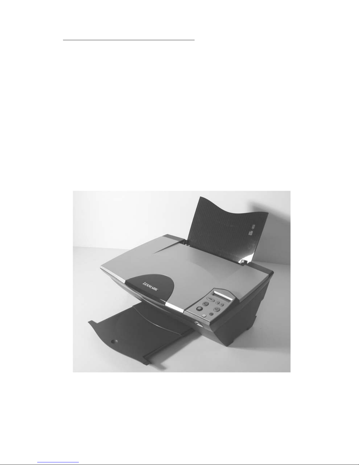
The Lexmark™ 3300 Series (4479-XXX) All-In-One features an electromechanical color scanner, copier, and printer that creates characters and
graphics by composing programmed patterns of ink dots using a printhead
and liquid ink. The printhead uses small heater plates and nozzles to control
ink flow and the formation of characters on the print media. The printhead
assembly and ink supply are combined into a single-unit print cartridge
available as a customer replaceable supply item. Dual printheads provide
color and true black printing without changing printheads. The number and
size of inkjets or nozzles in the printhead determines the overall quality and
capability of the printer. The black print cartridge has a total of 640 nozzles
and installs on the left. The color cartridge has a total of 480 nozzles installs
on the right. The photo cartridge has a total of 480 nozzles and installs on
the left. The All-In-One is capable of printing in two directions from either
cartridge.
General information 1-1

4479-XXX
Specifications
Scanner
Scanner Type Flatbed, CIS
Scan Modes True Color:
• 48 bit internal
• 24 bit external
Gray Mode:
• 16 bit internal
• 8 bit external
Text/Line Art:
• 1 bit per pixel
Scan Method One-pass scanning
Scan Area • 8.5 x 11.7 inches
• 216 x 297 mm
Scan Resolution Flatbed Scanning:
• Horizontal: 600 ppi (optical)
• Vertical: 2400 ppi
• Interpolated: 19,200 x 19,200
Resolutions
Mode Scan resolution Print resolution
Quick 150 x 150 ppi grayscale 300 x 600 dpi
Normal 300 x 300 ppi grayscale 600 x 600 dpi
Photo 600 x 600 ppi grayscale 2400 x 1200 dpi
Quick 150 x 150 ppi color 300 x 600 dpi
Normal 200 x 200 ppi color 600 x 600 dpi
Photo 300 x 300 ppi color 2400 x 1200 dpi
1-2 Service Manual

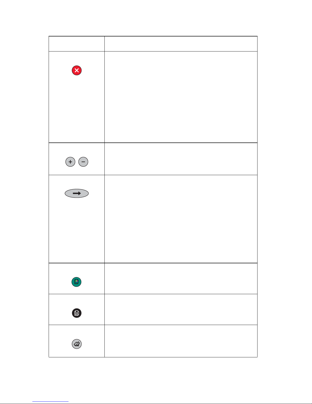
Control panel
The control panel is set up to function in scan and copy mode. The LCD
offers different options depending upon the mode.
4479-XXX
Buttons Functions
Power The Power button turns the power on and off when the
All-In-One is idle.
When the All-In-One is on and performing a
standalone or computer based print job, pressing the
Power button cancels the print job and sends a printer
initiated “cancel print” alert to the computer. The
All-In-One will power off after the page has been
ejected.
During a computer scan job, this button cancels the job
by sending a “scan abort” command to the computer.
During a computer copy job, this button performs a
combination command, to cancel the print and scan
job.
During a standalone copy job, this button cancels the
copy job and ejects the page.
General information 1-3
4479-XXX
Buttons Functions
Cancel During a computer print job, the Cancel button cancels
the job by sending the “cancel print” alert to the
computer, and the ejects the page.
During a computer scan job, this button cancels the job
by sending a “scan abort” command to the computer.
During a computer copy job, this button performs a
combination command to cancel the print and scan
job.
During a standalone copy job, this button cancels the
copy job and ejects the page.
The All-In-One stays on after a job has been canceled.
+/- When the LCD is on the default page, the +/- buttons
are used to increase or decrease the number of
copies. When in other menus, the +/- buttons are used
to scroll through the available settings.
Arrow The Arrow button is used to scroll through the available
menus. For this reason, the Arrow button is also
referred to as the menu button. Each time the Arrow
button is pressed, the next menu item on the LCD is
selected. If a setting in a menu is changed, pressing
the Arrow button will save the setting and proceed to
the next menu item.
The Arrow button is also used during special
conditions when the user needs to make a selection. In
all cases where a selection is necessary, the +/-
buttons are used to scroll through the choices and the
Arrow
Color Copy The All-In-One is equipped with a green Color Copy
button. The primary function of the Color Copy button
is to initiate color copies when the All-In-One is idle.
Black Copy The All-In-One is equipped with a Black Copy button.
The primary function of the Black Copy button is to
initiate grayscale copies when the All-In-One is idle.
button is used to make the selection.
Scan Pressing the Scan button sends a message to the host
1-4 Service Manual
computer causing the All-In-One Center to open and
perform a preview. The Scan button has no function
defined for non-host attached operation.

Maintenance approach
The diagnostic information in this manual leads you to the correct field
replaceable unit (FRU) or part. Use the error codes, symptom tables,
service checks, and diagnostic aids to determine the symptom and repair
the failure.
After you complete the repair, perform tests as needed to verify the repair.
Tools required for service
• Flat-blade screwdriver
• #1 Phillips screwdriver
• #2 Phillips screwdriver
• Spring hook
• Analog or digital multimeter
4479-XXX
General information 1-5

4479-XXX
Acronyms
ADF Automatic Document Feeder
B/M Bill of Material
CCD Charge Coupled Device
CIS Contact Image Sensor
DBCS Double Byte Character Set
EOF End of Form
ESD Electrostatic Discharge
FFC Flexible Flat Cable
FPC Flat Printhead Cable
FRU Field Replaceable Unit
HVPS High Voltage Power Supply
LCD Liquid Crystal Display
LED Light-Emitting Diode
LVPS Low Voltage Power Supply
MPF Multipurpose Feeder
NVRAM Nonvolatile Random Access Memory
OEM Original Equipment Manufacturer
POST Power-On Self Test
ROM Read Only Memory
SBCS Single Byte Character Set
USB Universal Serial Bus
V ac Volts alternating current
V dc Volts direct current
ZIF Zero Insertion Force
1-6 Service Manual

4479-XXX
2. Diagnostic information
Use the error code tables, post symptom table, symptom tables, and service
checks in this chapter to determine the All-In-One failure.
Start
Power-On Self Test (POST) sequence
Press the Power button to turn on the All-In-One.
1. The Power button indicator light comes on.
2. Lexmark 3300 Series appears on the LCD.
3. The carrier moves off the maintenance station, and then returns.
4. The paper feed motor runs, and then stops.
5. The Contact Image Sensor (CIS) moves to the left, and then returns.
6. Copies:1 appears on the LCD.
If the printer completes POST with no errors, go to “Symptom tables” on
page 2-10, locate the symptom, and take the appropriate action.
If the printer does not complete POST, go to “POST symptom table” on
page 2-9, locate the symptom, and take the appropriate action.
Error codes
POST errors
Code Name Description Action
0300 NVRAM R/W An error was detected
in reading or writing
NVRAM.
0301 Memory
Failure
Unable to initialize
memory
Replace the system
board.
Replace the system
board.
Diagnostic information
2-1

4479-XXX
Code Name Description Action
0302 Hardware
Failure
0303 ROM
Checksum
Failure
General hardware
failure (unable to
localize failure to a
specific system)
Corrupted ROM Replace the system
Replace the system
board.
board.
Catastrophic errors
In this state, the All-In-One is in an error mode such that operation
cannot continue. These errors affect the entire All-In-One. The LCD
is on and operating. An error message appears on the LCD. The
power LED blinks continuously and all button presses are ignored
except for the power button which resets the machine. The All-InOne accepts data, but discards it and does not respond.
Code Name Description Action
1202 Data Error Incorrect data has
been sent from the
host computer to the
All-In-One.
1204 Printhead
Programming
Unable to program
pseudo-random
printhead ID
Unplug the All-In-One;
wait a few seconds,
then plug the
All-In-One back in and
turn the power on. If
the error remains,
replace the USB
cable. If the error
continues, replace the
system board.
Replace print
cartridge(s).
2-2 Service Manual

Code Name Description Action
4479-XXX
1207 Paper System
Error
1209 FLASH
Programming
Error
A paper system error
control failure was
detected.
Cannot program
FLASH memory
Clear the paper path.
Unplug the All-In-One;
wait a few seconds,
then plug the
All-In-One back in and
turn the power on. If
the error remains,
clean the NVRAM by
pressing the Black
Copy button and
Power button
simultaneously until
the Mfg Menu
Enabled message
appears. Select Clean
NVRAM. If the error
continues, replace the
system board.
Unplug the All-In-One;
wait a few seconds,
then plug the
All-In-One back in and
turn the power on. If
the error remains,
replace the USB
cable. If the error
continues, replace the
system board.
1211 USB Error An error was detected
1212 Watchdog
Error
in USB hardware, or
invalid results occurred
in USB code.
Indicates printer
system was reset by
Watchdog timer;
Subsystem stall failure
Unplug the All-In-One;
wait a few seconds,
then plug the
All-In-One back in and
turn the power on. If
the error remains,
replace the USB
cable. If the error
continues, replace the
system board.
Unplug the All-In-One;
wait 5 minutes, then
plug the All-In-One
back in and turn the
power on. If the error
remains, replace the
system board.
Diagnostic information
2-3

4479-XXX
Code Name Description Action
1213 Data Abort
Error
Firmware attempted to
load or store to an
invalid address.
1214 Invalid
Processor
Mode Error
Indicates the ARM
processor was in an
incorrect mode to
perform the requested
operation
1215 Math Error There is a problem
doing math, such as
dividing by zero.
Unplug the All-In-One;
wait a few seconds,
then plug the
All-In-One back in and
turn the power on. If
the error remains,
replace the system
board.
Unplug the All-In-One;
wait a few seconds,
then plug the
All-In-One back in and
turn the power on. If
the error remains,
replace the system
board.
Unplug the All-In-One;
wait a few seconds,
then plug the
All-In-One back in and
turn the power on. If
the error remains,
replace the system
board.
1216 Mailbox Error There is a problem with
the internal mailbox
messaging system.
1217 Temperature
Error
There is a problem
determining
temperature.
Unplug the All-In-One;
wait a few seconds,
then plug the
All-In-One back in and
turn the power on. If
the error remains,
replace the system
board.
Replace print
cartridge(s).
2-4 Service Manual

Code Name Description Action
4479-XXX
1218 Serial Flash
Error
1219 Undefined
Signal Error
Invalid parameters
have been passed to
ReadFlashPage.
Microprocessor has
encountered a bad
signal (other than an
abort, illegal
instruction, or
arithmetic exception).
Unplug the All-In-One;
wait a few seconds,
then plug the
All-In-One back in and
turn the power on. If
the error remains,
clean the NVRAM by
pressing the Black
Copy button and
Power button
simultaneously until
the Mfg Menu
Enabled message
appears. Select Clean
NVRAM. If the error
continues, replace the
system board.
Unplug the All-In-One;
wait a few seconds,
then plug the
All-In-One back in and
turn the power on. If
the error remains,
replace the system
board.
2200 Scan Carrier
Stall
120A Undefined
Error
The scan carrier has
stalled.
Microprocessor has
encountered an abort
or undefined
instruction.
Unplug the All-In-One;
wait a few seconds,
then plug the
All-In-One back in and
turn the power on. If
the error remains,
replace the system
board.
Unplug the All-In-One;
wait a few seconds,
then plug the
All-In-One back in and
turn the power on. If
the error remains,
replace the system
board.
Diagnostic information
2-5
 Loading...