

Page 1

Lexmark™ 310 Series
Photo Jetprinter™
• Table of Contents
•Start Diagnostics
• Safety and Notices
4300-XXX
• Trademarks
•Index
Lexmark and Lexmark with diamond
design are trade ma rks of Lexmark
International, Inc., registered in the
United States and/or ot her countries.
Page 2

4300-XXX
Editi on: March 24, 2006
The following paragraph does not apply to any country where such provisions are
inconsistent with local law: LEXMAR K INTERNATIONAL, INC. PROVIDES THIS
PUBLICATION “AS IS” WITHOUT WARRANTY OF ANY KIND, EITHER EXPRESS OR
IMPLIED, INCLUDING , BUT NOT LIMITED TO, THE IMPLIED WARRANTIES OF
MERCHANTABILITY OR FITNESS FOR A PARTICULAR PURPOSE. Some states do
not all o w di sc la im er o f e x pres s o r i mpl i ed wa rr an tie s i n c ertai n t ra ns act ion s; t he refore, t hi s
statement may not apply to you.
This publication could include technical inaccuracies or typographical errors. Changes are
periodically made to the info rmation herein; these changes wil l be incorporated in later
editions. Improvements or changes in the products or the programs described may be
made at any time.
Comments may be addressed to Le xmark International, Inc., Department D22A /032-2 ,
740 West New Circle Road, Lexington, Kentucky 40550, U.S.A or e-mail at
ServiceInfoAndTraining@Lexmark.com. Lexmark may use or distribute any of the
information you supply in any way it believes appropriat e without incurring any obligation
to yo u.
Lexmark and Lexmark with diamond design are trademar ks of Lexmark International,
Inc. , registered in the Unit ed States and/or other countries.
Other trademarks are the propert y of their respec tive owners.
© 2004 Lexmark Inte rna t io nal , Inc.
All rights reserved.
UNITED STATES GOVERNMENT RIGHTS
This software and any accompanying documentation provided under this agreement are
commercial computer sof tware and documentation developed excl usively at private
expense.
U.S.A. P/N 12G9437
Japanese P/N 12G9445
Page 3

4300-XXX
Table of Contents
Preface. . . . . . . . . . . . . . . . . . . . . . . . . . . . . . . . . . . . . . . . . . . . . . . . .v
Safety information. . . . . . . . . . . . . . . . . . . . . . . . . . . . . . . . . . . . . . . vi
General information . . . . . . . . . . . . . . . . . . . . . . . . . . . . . . . . . . . . 1-1
Supported memory cards. . . . . . . . . . . . . . . . . . . . . . . . . . . . . . . 1-2
Control panel and menu . . . . . . . . . . . . . . . . . . . . . . . . . . . . . . . . . . 1-2
Using the control panel . . . . . . . . . . . . . . . . . . . . . . . . . . . . . . . . 1-2
Control panel buttons. . . . . . . . . . . . . . . . . . . . . . . . . . . . . . . . . . 1-3
Error messages . . . . . . . . . . . . . . . . . . . . . . . . . . . . . . . . . . . . . . 1-5
Resolution and print speed . . . . . . . . . . . . . . . . . . . . . . . . . . . . . 1-7
Maintenance approach . . . . . . . . . . . . . . . . . . . . . . . . . . . . . . . . . . . 1-8
Maintenance. . . . . . . . . . . . . . . . . . . . . . . . . . . . . . . . . . . . . . . . . 1-8
Maintenance menu. . . . . . . . . . . . . . . . . . . . . . . . . . . . . . . . . . . . 1-8
Abbreviations . . . . . . . . . . . . . . . . . . . . . . . . . . . . . . . . . . . . . . . . . . 1-9
Diagnostic information . . . . . . . . . . . . . . . . . . . . . . . . . . . . . . . . . 2-1
Start . . . . . . . . . . . . . . . . . . . . . . . . . . . . . . . . . . . . . . . . . . . . . . . . . 2-1
Power-On-Self-Test (POST) sequence . . . . . . . . . . . . . . . . . . . . 2-1
POST Symptom Tabl e . . . . . . . . . . . . . . . . . . . . . . . . . . . . . . . . 2-1
Sym p tom ta b le s . . . . . . . . . . . . . . . . . . . . . . . . . . . . . . . . . . . . . . 2-2
Service checks . . . . . . . . . . . . . . . . . . . . . . . . . . . . . . . . . . . . . . . . . 2-4
Maintenance station service check . . . . . . . . . . . . . . . . . . . . . . . 2-4
Control panel LCD/LED/button service check . . . . . . . . . . . . . . . 2-5
Paper feed service check. . . . . . . . . . . . . . . . . . . . . . . . . . . . . . . 2-5
Paper path service check. . . . . . . . . . . . . . . . . . . . . . . . . . . . . . . 2-7
Power service check . . . . . . . . . . . . . . . . . . . . . . . . . . . . . . . . . . 2-7
Print quality service check . . . . . . . . . . . . . . . . . . . . . . . . . . . . . . 2-8
Carrier transport service check . . . . . . . . . . . . . . . . . . . . . . . . . . 2-9
Pictbridge service check . . . . . . . . . . . . . . . . . . . . . . . . . . . . . . 2-10
Diagnostic aids . . . . . . . . . . . . . . . . . . . . . . . . . . . . . . . . . . . . . . . . 3-1
Self Test mode. . . . . . . . . . . . . . . . . . . . . . . . . . . . . . . . . . . . . . . 3-1
Repair informatio n . . . . . . . . . . . . . . . . . . . . . . . . . . . . . . . . . . . . . 4-1
Handling ESD-sensitive parts . . . . . . . . . . . . . . . . . . . . . . . . . . . . . . 4-1
Removal procedures . . . . . . . . . . . . . . . . . . . . . . . . . . . . . . . . . . . . 4-2
Cartridge access door removal . . . . . . . . . . . . . . . . . . . . . . . . . . 4-2
Rubber base removal. . . . . . . . . . . . . . . . . . . . . . . . . . . . . . . . . . 4-3
Rear cover removal . . . . . . . . . . . . . . . . . . . . . . . . . . . . . . . . . . . 4-4
Front cover removal. . . . . . . . . . . . . . . . . . . . . . . . . . . . . . . . . . . 4-5
System board removal. . . . . . . . . . . . . . . . . . . . . . . . . . . . . . . . . 4-5
Carrier transport removal . . . . . . . . . . . . . . . . . . . . . . . . . . . . . . . 4-7
Maintenance station removal. . . . . . . . . . . . . . . . . . . . . . . . . . . 4-12
Photo exit guide removal . . . . . . . . . . . . . . . . . . . . . . . . . . . . . . 4-15
iii
Page 4

4300-XXX
Card reader removal . . . . . . . . . . . . . . . . . . . . . . . . . . . . . . . . . .4-15
Connector locations . . . . . . . . . . . . . . . . . . . . . . . . . . . . . . . . . . . .5-1
System board connectors . . . . . . . . . . . . . . . . . . . . . . . . . . . . . . .5-1
LCD board connectors . . . . . . . . . . . . . . . . . . . . . . . . . . . . . . . . .5-3
Card reader connector . . . . . . . . . . . . . . . . . . . . . . . . . . . . . . . . .5-4
Preventive maintenance . . . . . . . . . . . . . . . . . . . . . . . . . . . . . . . . .6-1
Lubrication specifications . . . . . . . . . . . . . . . . . . . . . . . . . . . . . . . . .6-1
Parts catalog . . . . . . . . . . . . . . . . . . . . . . . . . . . . . . . . . . . . . . . . . .7-1
How to use the parts catalog . . . . . . . . . . . . . . . . . . . . . . . . . . . . . . .7-1
Assembly 1: Covers . . . . . . . . . . . . . . . . . . . . . . . . . . . . . . . . . . .7-2
Assembly 2: Electronics/carrier transport . . . . . . . . . . . . . . . . . . .7-4
Index . . . . . . . . . . . . . . . . . . . . . . . . . . . . . . . . . . . . . . . . . . . . . . . . X-1
iv Service Manual
Page 5

4300-XXX
Preface
This manual describes the 310 Series Photo Jetprinter by Lexmark
(4300-XXX) and contains maintenance procedures for service
personnel. It is divided into the following chapters:
1. Gene r al Infor m ation contains a general description of the
printer and the maintenance approach used to repair it. Special
tools and test equipment are listed in this chapter, as well as
general environmental and safety instructions.
2. Diagnostic Information contains an error indicator table,
symptom tables, and service checks used to isolate failing field
replaceable units (FRUs).
3. Diagnostic Aids contains tests and checks used to locate or
repeat symptoms of printer problems.
4. Repair Informa tio n provides instructions for making printer
adjustments and removing and installing FRUs.
5. Connec tor Locations uses illustrations to identify the
connector locations and test points on the printer.
6. Preventive Maintenance contains the lubrication specifications
and recommendations to prevent problems.
7. Parts Catalog co ntains illustrations and part numbers for
individual FRUs.
Preface v
Page 6

4300-XXX
Safety information
• This product is designed, tested and approved to meet strict
global safety standards with the use of specific Lexmark
components. The safety features of some parts may not always
be obvious. Lexmark is not responsible for the use of other
replacement parts.
• The maintenance information for this product has been
prepared for use by a professional service person and is not
intended to be used by others.
• There may be an increased risk of electric shock and personal
injury dur ing disassem bly and ser v icing of this product.
Professional service personnel should understand this and take
necessary precautions.
Consignes de Sécurité
• Ce produit a été conçu, testé et approuvé pour respecter les
normes strictes de sécurité globale lors de l'utilisation de
composants Lexmark spécifiqu es. Les caractéristiques de
sécurité de certains éléments ne sont pas toujours évidentes.
Lexmark ne peut être tenu responsable de l'utilisation d'aut res
pièces de rechange.
• Les consignes d'entretien et de réparation de ce produit
s'adressent uniquement à un personnel de m aintenance
qualifié.
• Le démontage et l'entretien de ce produit pouvant présenter
certains risques électriques, le personnel d'entretien qualifié
devra prendre toutes les précautions nécessaires.
vi Service Manual
Page 7

4300-XXX
Norme di sicurezza
• Il pr odotto è stato progettato, testato e approvato in conformità a
severi standard di sicurezza e per l’utiliz zo con componenti
Lexmark specifici. Le caratteristiche di sicurezza di alcune parti
non sempre sono di immediata comprensione. Lexmark non è
responsabile per l’utilizzo di parti di ricambio di altri produttori.
• Le informazioni riguardanti la manutenzione di questo prodotto
sono indirizzate soltanto al personale di assistenza autorizzato.
• Durante lo smontaggio e la manutenzione di questo prodotto, il
rischio di subire scosse elettriche e danni alla persona è più
elevato. Il personale di assistenza autorizzato, deve, quindi,
adottare le precauzioni necessarie.
Sicherheitshinweise
• Dieses Produkt und die zugehörigen Komponenten wurden
entworfen und getestet, um beim Einsatz die weltweit gültigen
Sicherheitsanforderungen zu erfüllen. Die sicherheitsrelevanten
Funktionen der Bauteile und Optionen sind nicht immer
offensichtlich. Sofern Teile eingesetzt werden, die nicht von
Lexmark sind, wird von Lexmark keinerlei Verantwortung oder
Haftung für dieses Produkt übernommen.
• Die Wartungsinformationen für dieses Produkt sind
ausschließlich für die Verwendung durch einen
Wartungsfachmann bestimmt.
• Während des Auseinandernehmens und der Wartung des
Geräts besteht ein zusätzliches Risiko eines elektrischen
Schlags und körperlicher Verletzung. Das zuständige
Fachpersonal sollte entsprechende Vorsichtsmaßnahmen
treffen.
Safety i n fo rmat io n vii
Page 8

4300-XXX
Pautas de Seguridad
• Este producto se ha diseñado, verificado y aprobado para
cumplir los más estrictos estándares de seguridad global
usando los componentes específicos de Lexmark. Puede que
las características de seguridad de algunas piezas no sean
siempre evidentes. Lexmark no se hace responsable del uso de
otras piezas de recambio.
• La in formaci ón sobre el mantenimiento de este producto está
dirigida exclusivamente al personal cualificado de
mantenimiento.
• Existe mayor riesgo de descarga eléctrica y de daños
personales durante el desmontaje y la reparación de la
máquina. El personal cualificado debe ser conscien te de este
peligro y tomar las precauciones necesarias.
Informações de Segurança
• Este produto foi concebido, testado e aprovado para satisfazer
os padrões globais de segurança na utilização de componentes
específicos da Lexmark. As funções de segurança de alguns
dos componentes podem não ser sempre óbvias. A Lexmark
não é responsável pela utilização de outros com ponent es de
substituição.
• As informações de segurança relativas a este produto
destinam-se a profissionais destes serv iços e não devem s er
utilizadas por outras pessoas.
• Risco de choques eléctricos e ferimentos graves durante a
desmontagem e manutenção deste produto. Os profissionais
destes serviços devem estar avisados deste facto e tomar os
cuidados necessári os.
viii Service Manual
Page 9

4300-XXX
Informació de Seguretat
• Aquest producte està dissenyat, comprovat i aprovat per tal
d'acomplir les estrictes normes de seguretat globals amb la
utililització de components específics de Lexmark. Les
característiques de seguretat d'algunes peces pot ser que no
sempre siguin òbvies. Lexmark no es responsabilitza de l'us
d'altres peces de recanvi.
• La informació pel manteniment d’aquest producte està
orientada exclusivament a professionals i no està destinada a
ningú que no ho sigui.
• El risc de xoc elèctric i de danys personals pot augmentar
durant el procés de desmuntatge i de servei d’aquest producte.
El personal professional ha d’estar-ne assabentat i prendre les
mesures convenients.
Safe ty inform at ion ix
Page 10
4300-XXX
x Service Manual
Page 11
4300-XXX
1. Gen e r a l in for matio n
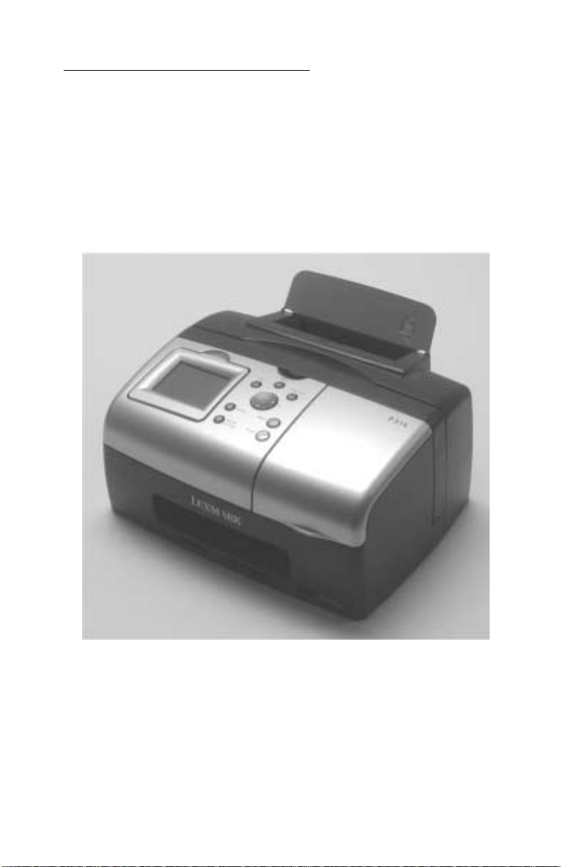
The Lexmark 310 Series Photo Jetprinter (4300-XXX) is designed to
be a small personal inkjet printer specifically for standalone portable
photographic printing. The photoprinter incor p orates a new photo
control operator panel into the cover set and slots to support the
compact flash and smar t media.
General information 1-1
Page 12

4300-XXX
Supported memory cards
1. Microdrive
2. CompactFlash Type I and Type II
3. Secure Digital (SD)
4. MultiMedia Card
5. SmartMedia
6. xD Picture Card
7. Memory Stick, Memory Stick PRO, Memory Stick Duo (with
adapter), Memor y Stick PRO Duo (with adapter)
Control panel and men u
Using the control pa nel
The control panel provides a blue-LED-backlit Power button. When
the machine is powered down, the Power LED turns off.
The card reader bezel has a single blue LED to indicate memory
card inserted and memo r y card activity. When a memory card is
inserted, the LED is lit solid. When the card is being actively read
from or written to, the LED blinks at the prescribed rate. When the
machine is powered down, the LED turns off.
1-2 Service Manual
Page 13

4300-XXX
Control panel buttons
Buttons Functions
Power Turns power on. At power up, the print er tu rns on the
card reader LED and the color graphics LCD.
Start Activat es printing after selections hav e been made.
Up Arrow Navigates menu items on the LCD. In the Photo Card
mode, this bu tton allows y ou to skip for ward throug h 10
pictures on the photo card to vie w every 10
the LCD.
Down Arrow Navigates menu items on the LCD. In the Photo Card
mode, this button allo ws you to skip ba ckward through
10 picture s on the ph oto card t o view e v ery 10
in the LCD.
Left Arrow Manipulates menu selections on the LCD. Pressing
this butt on changes to the preceding option for the
current active menu item. If the last item is selected
and the right arrow is pressed, the selecti ons loop to
the beginning of the list.
Right Arrow Manipulates menu selections on the LCD. Pressing
this butt on changes to the nex t option for the cur rent
active menu item. If the last item is selected and the
right arrow is pressed, the selections loop to the top of
the list.
th
picture i n
th
picture
Number of Prints Increments the copy count displ ayed on the lower left
of the LCD in Photo.
Select Allows you to choose an option from a menu. When
Stop/Clear Discontin ues the current activ it y and returns the
moving through the menu items , you can scroll thr ough
settings for a menu item with the Left and Right Arrow
buttons. To save the setting s, pres s Select.
display back one level in the menu. It terminates any
active print jobs, including ejecting the unfinished
printout.
General information 1-3
Page 14

4300-XXX
Buttons Functions
Menu Accesses the adv a nced functi ons of the pri nter. Opens
a menu structure containing all the settings or
functions pertaining to the current active mode.
Navigates th e menu using the Up Arrow and Down
Arrow buttons. To select the curre ntly displayed setting
option, press Select. Press the Menu button again to
exit.
Rotate Rotates the image in the LCD disp lay by 90°
counterclockwise for each time the button is pressed.
Rotates the Region of Int erest (ROI) when in the cr op
function of the Photo mode menu.
1-4 Service Manual
Page 15

4300-XXX
Error messages
Error
Paper out
occurred
Printhead
carrier jam
occurred
Paper jam
occurred
Action
required to
clear error
Load paper
and press
Select button
to feed.
Can the job be
continued?
(Yes) Press
Select to
reprint the last
page and other
pages.
(No) Press
Select to clear
message.
Can the job be
continued?
(Yes) Press
Select to
reprint the last
page and other
pages.
(No) Press
Select to clear
message.
Power
LED
Blinks un t il
message is
cleared. (In
DPS, the
camera can
clear this
message
also.)
Blinks un t il
message is
cleared.
Blinks un t il
message is
cleared.
LCD title LCD main text
Paper out 1. Add paper.
2. Press
Select to
continue.
Carrier jam 1. Clear the
carrier jam.
2. Press
Select to
finish the
remaining
pages.
1. Clear the
carrier jam.
2. Press
Select to go
back and
retry your
job.
Paper jam 1. Clear the
paper jam.
2. Press
Select to
finish the
remaining
pages.
1. Clear the
paper jam.
2. Press
Select to go
back and
retry your
job.
Cover was
open when a
print job was
initiated.
Close the
cover to
automatically
resume job.
Blinks un t il
cover is
closed.
Cover open Close the
cover to
continue.
General information 1-5
Page 16

4300-XXX
Error
A missing
print
cartridge is
detected.
An alignment
error
occurred,
which means
tape was left
on the
cartridge or
sensor
failure.
User inserts
a card in the
wrong
orientation or
card is
damaged.
Action
required to
clear error
Automatically
clears when
print cartridges
are detected.
Press Select
to resta rt th e
alignment
process.
Message goes
away when
card is
removed or
inserted
correctly, or
when you
switch out of
Photo mode.
Power
LED
Blinks until
error is
cleared.
Blinks until
error is
cleared.
Blinks until
error is
cleared.
LCD title LCD main text
Cartridge
missing
Alignment
error
Card
problem
Install a color
print cartridge.
Ensure the
tape is
rem ove d from
the cartridge.
Press Select
to retry
alignment.
There is a
problem
reading the
memory card.
Ensure that it
is not
damaged and
is inserted
correctly.
A second
media card is
inserted.
Message goes
away when
second card is
removed.
1-6 Service Manual
Blinks until
error is
cleared.
Card
problem
A second
memory card
has been
detected.
Please remov e
the second
memory card.
Page 17

4300-XXX
Error
A card is
inserted that
has no
images.
A card is
inserted that
has incorrect
format. An
error is
display ed that
the card
format is
unsupported.
Action
required to
clear error
Message goes
awa y when
card is
removed.
Message goes
awa y when
card is
removed.
Power
LED
Blinks un t il
error is
cleared.
Blinks un t il
error is
cleared.
Resolution and print speed
Color
Glossy/Photo Media:
• Normal —1200 x 1200 dpi
• Photo — 2400 x 1200 dpi
• Max — 4800 x 1200 dpi
LCD title LCD main text
Photo
mode
Card
format
No supported
images found
on the memory
card.
The memory
card formatt ing
is not
supported.
Format the
card in your
digital camera.
4 x 6 Borderless on photo media
35/70/140 seconds
General information 1-7
Page 18

4300-XXX
Maintenance approach
The diagnostic information in this manual leads you to the correct
field replaceable unit (FRU) or part. Use the error indicator charts,
symptom index, service checks, and diagnostic aids to determine
the symptom and repair the failure. Begin with “Start” on page 2-1.
This printer can be serviced without being connected to a host
computer.
After you complete the repair, perf orm tests as needed to verify the
repair.
Maintenance
Maintenance items are listed in the menus and include a list of
options related to printhead cartridge management and testing. The
following items are in the Maintenance menu while in photo mode in
the order listed below.
• Ink Leve l
• Change Cartr idge
• Align Cartridge
• Clean Cartr idge
• Print Test Page
Maintenance menu
Ink Levels — Press Select to display ink levels. Press Stop/Clear to
return to the default mode screen.
Change Cartridge — When Change Cartridge is selected, screens
are shown in sequence simulating a “movie” that shows how to
change the cartridge in the printer. The “movie” continues to run until
new cartridges are detected or until you press Stop/Clear.
Align Cartridge — Press Select to align the print cartridge and print
an auto-alignment page. When the page has finished printing, the
LCD will disp lay “Automatic Alignment Complete” for two seconds,
then return to the default screen.
1-8 Service Manual
Page 19

4300-XXX
Clean Cartr idge — Press Select to clean the cartridge and print a
cleaning page. When the page has finished printing, the LCD will
display “Cleaning Complete” for two seconds, then return to the
default screen.
Print Test Page — Press Select to print a test page. When the page
has finished printing, the LCD will display “Prin ting Complete”, then
return to the default screen.
Abbreviations
CSU Customer Setup
EOF End of Forms
ESD E lectr ostatic Discharge
FRU F ield Replac eable Unit
HV High Voltage
LCD Liquid Crystal Display
LED Light-Emitting Diode
LV Low Voltage
NVRAM Nonvolatile Random Access Memory
OEM Original Equipment Manufacturer
POST Power-On Self Test
ROI Region of Interest
V ac Volts alternating current
V dc Volts direct current
General information 1-9
Page 20

4300-XXX
1-10 Service Manual
Page 21

4300-XXX
2. Diagnostic information
Start
If no error appears, go to “Power-On-Self-Test (POST) sequence” on
page 2-1.
Power-On-Self-Test (POST) sequence
Plug the printer in and press the power button. Check for a correct
POST operation by observing the following:
1. LED turns on.
2. Power button lights up then turns off.
3. The carrier moves off the maintenance station and then returns.
4. Pap er feed motor cycles then stops.
5. The LCD displays “Photo Mode”; “Please insert memory card or
connect pictbridge camera.”
6. Blue indicator light near the card reader slots stays on when
card is present.
POST Symptom Table
Symptom Action
No motors run Go to the “Power service chec k” on
page 2-7.
Paper feed gears do not turn Go to the “Paper fee d service
check” on page 2-5.
• Carrier does not move
• Carrier slams side frame
• Blank display
• Disp lay diff icult to read
• Display OK, buttons do not function
• One or more b uttons do not function
Go to the “Carrier transport service
check” on page 2-9.
Go to the
“Control panel LCD/
LED/button service check” on
page 2-5
.
Diagnostic information 2-1
Page 22

4300-XXX
Symptom tables
Locate the symptom in the following tables and take the appropriate
action.
Carrier transport problems
Symptom Action
• No carrier movement
• Slow carrier movement
• Carrier stops
• Carrier slams sid e fra m e
Go to the “Carrier transport service
check” on page 2-9.
Maintenance station problems
Symptom Action
• Fails to cap the printhead
• Fails to clean the printhead
Go to the “Maintenance station
service check” on page 2-4.
Paper feed problems
Symptom Action
Paper fails to stop at fir st print line. Go to the “Paper feed service check”
on page 2-5.
• Fails to pick paper
• Picks more than one sheet of
paper
• Picks paper but fails t o feed
• Paper jams
• Paper fails to exit
• Noisy paper feed
Go to the “Paper feed service check”
on page 2-5.
Paper sk ews Go to the “Paper path service check”
on page 2-7.
2-2 Service Manual
Page 23

4300-XXX
Power prob le ms
Symptom Action
No po we r in printe r Go to t h e “Power service check” on
page 2-7.
Print quality problems
Symptom Action
• Light print
• Fuzzy print
• Carrier moves but does not print
• Printhead drying prematurely
• Excessive ink f low (Flooding)
• Horizontal banding
• Ink smearing
• Vertical streaks on paper
• Prin t lin e s crow de d
Go to the “Prin t qu a lit y service c heck ”
on page 2-8.
Go to the “Paper feed service chec k”
on page 2-5.
Pictbridge problems
Symptom Action
Fails to work Check the Pictbridge connections . If
the connections are okay, go to
“Pictbridge service check” on
page 2-10
.
Diagnostic information 2-3
Page 24

4300-XXX
Service checks
Maintenance station service check
The maintenance station has two functions:
1. Cleans the printhead nozzles during the print operation.
2. When the printer is not in use, it seals the printhead to prevent
the nozzles from drying.
Parts / FRUs Action
1 Maintenance
Station Assembly
2 Wiper A worn wiper causes degraded print quality just
3 Cap A worn cap causes the printhead nozzles to dry
As the car r ie r m oves to th e le ft over the
maintenance station, a slot on the left side of the
carrier engages a tab on the sled of the
maintenance station causing the cap to rise and
seal the printhead. Car rier movement to the right
will uncap the printhead. The wiper cleans the
printhead nozzl es as the carrier leav es the
maintenance station. The wiper cleans the
printhead only when the carrier is moving to the
right. There should be no wip ing action of the
printhead nozzles when the carrier is moving to
the left. Afte r the cleani ng operat ion is complete , a
tab on the maintenanc e station engages a tab on
the carrier, causing the wiper and sled to lower.
Check the m aintenance station f or worn or brok en
parts.
after a maintenan ce cleaning. Check for loose or
worn wiper.
and clog. Check for loose or worn cap.
2-4 Service Manual
Page 25

4300-XXX
Control panel LCD/LED/button service check
Parts / FRUs Action
1 LCD/LED Buttons Check all connections on the system board. If
connections are oka y but the buttons or LCD do
not function correct ly, replace the front cover with
LCD/CD/OP/CD . Go to
on page 4-5
Note: If buttons or LCD fail, replace the front
cover.
.
“Front c ove r remova l ”
Paper feed service check
If your printer does not have paper jams, continue with this service
check. If your printer does have a paper jam, examine it for the
following before you begin the service check:
• Check the entire paper path for obstructions.
• Be sure not to overfill the sheet feeder.
• Be sure the correct type of paper is being used.
• Check for static in the paper.
Parts / FRUs Action
1 System Board Check fo r approximat ely +29 V dc connector J2
pins 1 and 2 on the system board. If the voltage is
incorrect, replace the system board. If correct,
check for moto r pins shorted to t he motor h ousi ng.
If you find a shorted pin, replace the print engine
assembly.
Diagnostic information 2-5
Page 26

4300-XXX
Parts / FRUs Action
2 Paper Feed Motor
Print Engine
Assembly
System Board
3 Gears Check for binds in the gear train and paper feed
A noisy or chattering motor or a motor that fa il s to
turn can be caused by:
• An open or short in the motor
• An open or short in the motor driver on the
system board
• A bind in the paper feed mechanism
Check for motor pins shorted to the motor
housing. If you f ind a shorted pin, replac e the print
engine assembly.
With the paper f eed m otor cable disconnected
from the system boar d, check f or appro ximat ely 18
ohms between pin 1 and 2 on the motor cable. If
correct, plug in t he printer and check the voltage
reading of app rox imat ely +2 9 V dc a t connect or J2
on pins 1 and 2. If the voltage re ading is incorr ect,
replace the system board.
Although the paper feeds in a forward direction
only, the paper feed motor turns in two directi ons.
If the paper feed motor turns in one direc tion only,
replace the system board.
mechanism by rotating the large feed roll by hand.
If you notice a bind, isolate it by removing one of
the small idler gears on the inside of the left side
frame. If any worn or binding gears or rolle rs are
found, replace the print engine assembly.
4 Paper Path Per form the “Paper path service check” on
page 2-7, starting at Step 1.
2-6 Service Manual
Page 27

4300-XXX
Paper path service check
Examine the printer for the following before you begin this service
check:
• Check the entire paper path for obstructions.
• Be sure the paper guides are not worn or broken and are
positioned against the paper without binding or buckling the
paper.
• Be sure the correct type of paper is being used.
• Be sure the printer is installed on a flat surface.
Parts / FRUs Action
1 Large and Small
Feed Rollers
2Small Feed Roller
Springs
3 Exit Roller
Star Rollers
Exit Drive Belt
and Tensioner
4 Sheet Feeder Check the followi ng for wear or damage :
5 End-of-Forms
Flag & Spring
Check fo r wear and binds.
Check fo r damage.
Check fo r wear and binds.
• Paper pick assembly.
• All parts inside the left and right edge guides.
Check fo r bi nds or damage.
Power service check
Parts / FRUs Action
1 Power Supply Check voltage reading of +29 V dc at connector
JP51 — pin 1.
If incorrect voltage or no vol tage, replace the
power supply.
Diagnostic information 2-7
Page 28

4300-XXX
Parts / FRUs Action
2 Printhead Cable
3 System Board If the symptom has not changed, replace the
Unplug the printer. Disconnect the printhead ca ble
and plug in the printer. Look for a symptom
change. Check the failing part for shorts and
replace as necessary.
system board.
Print quality servic e check
Parts / FRUs Action
1 Print Cartridge Be sure the printer contains good print cartridges.
2 Printhead Carrier
Assembly
3 Printhead
Cartridge
Reseat the printhead cable on the system board
and check the following parts for wear or damage:
• Print Cartridge Latch
• Latch Spring
• Carrier
To check the print cartridge nozzles, go to
“Self
Test mode” on page 3-1. Enter the self test
mode and arrow down, th en select “Clean (Nozzl e
Check)”.
Clean the print nozzles when you suspect the
nozzles are clogg ed or if the character s are not
printing completel y. When you clean the print
nozzles, a tes t l ine prints so you can see if the
cleaning process was successful.
4 Printhead Cable Check the gold-plated contacts on the end of the
cable that connect to the carrier for dirt and wear.
Use only a clean, dry cloth to clean the contacts.
Also, check the cabl e for damage. You may need
to remove th e cabl e fro m th e ca r r ie r to in sp e c t it.
5 Maintenance
Station
Intermittent nozz le f ail ures can b e caus ed b y wo rn
parts in the maintenance stat ion. Per form the
“Maintenance station service check” on page 2-4,
and then return to this check.
2-8 Service Manual
Page 29

4300-XXX
Parts / FRUs Action
6 Paper F eed Ink smudging and smearing can be caused by
paper problems or problems in the paper feed
area.
Check the fol lowing:
• Correct type of paper i s being used.
• Paper for curl or wrinkles.
• Feed rollers for wear, dirt, or looseness.
• Gears for wear or binds.
• Paper path for obstructions.
7 Tra nsport Blurre d print and voids can be caused by
problems in the transport area. Check the
following:
• Transport belt for wear and fu ll eng agement i nto
the carrier grip.
• Carrier guide rod f or wear or dirt.
• Carrier to carrier fr am e engagem ent should be
lubricated with grease P/N 99A0394.
Lubricate the carrie r guide rod and carrier fr ame
on both sides where the two top bearing
surfaces ride on the frame.
• Idler pulley parts for wear, damage, or
looseness.
Carrier transport service check
Parts / FRUs Action
1 Carrier Transport
Motor
Check the motor for binds or loose motor pulley.
Disconnect the carrier tr ansport motor J1 from the
system board. Check for approximately 18 ohms
between pins 1 and 2 on the motor cab le and for
shorted motor pins. If the reading is incorrect ,
replace the print engine assembly.
If the failure remains, replace the system board.
2 System Board Check connector J1 on the system board and
check for approximately 29 V dc at pins 1 and 2. If
incorrect, replace system board.
Diagnostic information 2-9
Page 30

4300-XXX
Parts / FRUs Action
3 Encoder Strip Verify that the encoder strip is installed correctly
and free of grease or dirt. If encoder strip is not
installed correctly, it can cause the carrier to slam
against the frame.
4 Carrier Guide
Rod
5 Transport Belt
Idler Pulley Parts
Carrier Frame
6 Printhead Cabl e Be sure all connectors are fully seated. Chec k the
7 Maintenance
Station
Clean the carrier rod.
Note: Lubricate the rod and the carri er rod bearing
surface.
Check for worn, loose or broken parts. Chec k for
obstructions blocking car ri er movement.
Carrier to carrier fra me engagem ent should be
lubricated with grease P/N 99A0394.
cables for damage.
A problem with the maintena nce station can caus e
carrier mov ement probl ems at the right marg in. Go
to the “Maintenance station service check” on
page 2-4.
Pictbridge service check
Parts / FRUs Action
1 Pictbridge Check all connections. Check for approximately 5
volts on pin 5 connector J7 on the system board. If
voltage i s incorrect, replace the system board. Go
to
“System board removal” on page 4-5.
2-10 Service Manual
Page 31

4300-XXX
3. Diagnostic aids
Self Test mode
To enter the Self Test mode, press the Up Arrow and the Menu
buttons simultaneously . To scroll the test items, press the Up Arrow,
Down Arrow, Left Arrow or Right Arrow buttons. To execute the
test item, press the Select button. The test items in the Self Test
mode menu are:
LCD test — Turns on all LCD pixels simul taneously to create a white
background so any machine with dead pixels can be identified.
Press the Stop/Clear button to return to the Test Menu.
LED t es t — Verifies that all the LED’s on t he machine work. The LED
test turns on the LED’s one by one for one second each
successively and automatically . This is repeated until the Stop/Clear
button is pressed, then it returns to the Test Menu.
Button test — Verifies that all buttons on the control panel work.
Removes numbers from the display as the associated button is
pressed. Number of Prints=1, Up=4, Left= 5 , Right=6, Down=7,
Select=8, Menu=A, Stop/Clear=B, Start=C, and Rotate=D. To return
to the Test Menu, press the Stop/Clear button.
Media card test — When this item is selected, if a media card is
inserted, a “Testing” message is displayed. If no media card is
inserted, a “No media card found” message displays. If a card is
present, it performs the read/write test of the media card. Then a
message is displayed indicating the type of media card found and
either “Success” or “Failure.” If the inserted media card is write-
protected, a Write-Protect” message displays. Press the Stop/Clear
button to return to the Test Menu.
Clean (Nozzle Check) — When selected, prints the Nozzle Cleaning
page. Returns to the Test menu when finished.
NVRAM dump — Prints the contents of the flash-emulated NVRAM.
Regular printing progress screens are shown during printing. After
completion, the displ ay returns to the Test Menu. Pressing Stop/
Clear during printing stops the job, ejects paper, and returns to the
Test Menu.
Diagnostic aids 3-1
Page 32

4300-XXX
Clear NVRAM — This function does a clear of the non protected
area of the Flash-emulated NVRAM by restoring values to default or
initializing the values to 0x00 or 0xFFs. When selected, a “Clearing”
message is displayed. If the function ends successfully, a “Success”
message is displayed. Press the Stop/Clear button to re tur n to the
Test Menu.
SRAM test — To verify all the address buses and data buses that
connect to the SRAM area work correctly, perform the read/write of
data to the SRAM area with all the address buses and data buses.
While checking, a “Testing” message is displayed. Then a “Success”
message is displayed for three seconds, or a “Failure” message is
displayed until cleared by pressing the Stop/Clear button.
3-2 Service Manual
Page 33

4300-XXX
4. Rep a ir in fo r m a t i on
This chapter explains how to make adjustments to the printer and
how to remove defective parts.
CAUTION: Read the following before handling electronic parts.
When working on the printer, always unplug the printer from the
electrical outlet. High voltage is present in the power supply as long
as it is plugged into the electrical outlet.
Handling ESD-sensitive parts
Many electronic products use parts that are known to be sensitive t o
electrostatic discharge (ESD). To prevent damage to ESD-sensitive
parts, follow the instructions below in addition to all the usual
precautions, such as turning off power before removing logic boards:
• Keep the ESD-sensitive part in its original shipping container
(a special “ESD bag”) until you are ready to install the part into the printer.
• Mak e the few er po ssi b le movem ents with your body t o preven t an increase
of static electricity from clothing fibers, carpets, and furniture.
• Put th e E SD wri st strap on your w rist . C onnect the w ris t band to the system
ground point. This discharges any static electricity in your body to the
printer.
• Hold the ESD-sensitive part by its edge connector shroud (cover); do not
touch its pin s . If y ou are rem oving a plugga ble module , use t he correct tool.
• Do not place the ESD-sensitive part on the printer cover or on a metal
table; if you need to put down the ESD-sensitive part for any reason, first
put it into its special bag.
• Printer covers and metal tables are electrical grounds. They increase the
risk of damage because they make a discharge path from your body
through the ESD-sensitive part. (Large metal objects can be discharge
paths without being grounded.)
• Prevent ESD-sensitive parts from being accidentally touched by other
personnel. Install printer covers when you are not working on the printer,
and do not put unprotected ESD-sensitive parts on a table.
• If possible, keep all ESD-sensitive parts in a grounded metal cabinet
(case).
• Be careful in working with ESD-sensitive parts when cold-weather heating
is used, because low humidity increases static electricity.
Repair information 4-1
Page 34

4300-XXX
Removal proced ur e s
The following procedures are arranged according to the name of the
printer part discussed. Unplug the power cord before removing any
parts.
Cartridge access door removal
1. Depress hinge (A) and lightly force access door to the right and
remove cartridge access door.
4-2 Service Manual
Page 35

4300-XXX
Rubber base removal
1. Remove six screws (A) from base.
2. Remove rubber base.
Repair information 4-3
Page 36

4300-XXX
Rear cover removal
1. Remove rubber base.
2. Remove two scre ws (A).
3. Depress two tabs (B).
4. Remove rear cover .
4-4 Service Manual
Page 37

4300-XXX
Front cover removal
1. Remove rubber base.
2. Re move rear cover.
3. Disconnect cable J6 (A) from LCD board.
4. Remove two screws (B).
5. Depress two tabs (C).
6. Re move front cover.
System board removal
1. Remove rubber base.
2. Re move rear cover.
3. Re move front cover.
4. Disconnect all cables from system board. Note routing of all
cables.
Repair information 4-5
Page 38

4300-XXX
5. Remove three screws (A). Be sure not to damage the EOF (B)
flag when reinstalling.
6. Remove the system board.
4-6 Service Manual
Page 39

4300-XXX
Carrier transport removal
1. Remove rubber base.
2. Re move rear cover.
3. Re move front cover.
4. Remove system board.
5. Unlatch the carrier cable clip (A).
6. Move carrier to center of printer.
Repair information 4-7
Page 40

4300-XXX
7. Remove retainer clips (B).
8. Remove carrier shaft through left side of printer.
4-8 Service Manual
Page 41

4300-XXX
9. Disconnect and remove the encoder strip (C). Note the
orientation of the encoder strip at the rear of the carrier.
Repair information 4-9
Page 42

4300-XXX
10. Remove the belt tensioner screw (D) if present.
4-10 Service Manual
Page 43

4300-XXX
11. Depress belt tensioner (E) and remove belt from the pulley (F)
on the carrier transport motor.
12. Remove carrier.
Repair information 4-11
Page 44

4300-XXX
Maintenance station removal
1. Remove rubber base.
2. Remove rear cover .
3. Remove front cover.
4. Disconnect connectors J3, J5, J7 and JP51 from the system
board.
5. Remove two screws (A) from base assembly.
4-12 Service Manual
Page 45

4300-XXX
6. Remove three screws (B) from the small exit feed roller
assembly.
7. Lift and remove small exit feed roller assembly.
8. Remove three screws (C) and the right side ground wire screw
from print engine.
9. Lift and remove print engine.
Repair information 4-13
Page 46

4300-XXX
10. Depress three latches (D).
11. Slide maintenance station forward and down to remove.
4-14 Service Manual
Page 47

4300-XXX
Photo exit guide removal
1. Remove rubber base.
2. Re move rear cover.
3. Re move front cover.
4. Remove print engine.
5. Remove two screws (A).
6. Lift photo exit guide up and out to remove.
Card reader removal
1. Remove rubber base.
2. Re move rear cover.
3. Re move front cover.
4. Remove print engine.
5. Remove photo exit guide.
6. Disconnect J3 and J5 from the system board.
7. Disconnect J4 from the card reader.
Repair information 4-15
Page 48

4300-XXX
8. Remove two screws (A) and the ground wires.
9. Remove ESD shield.
10. Remove card reader.
4-16 Service Manual
Page 49

4300-XXX
5. Connector locations
System board connectors
Connector Description Voltage
J1 Carrier Transport Motor pins 1 and 2 — 29 V
(approximate)
J2
J3
J4
J5
J7
J10
J11
J13
JP51
PS1
Paper F eed Motor pins 1 and 2 — 29 V
Card Reader
Control Panel
Card Reader
Pictbridge pin 5 — 5 V
Carrier
Paper Encoder Di al Sensor
Carrier
Power Supply pin 1 — 29 V
EOF
Connector locations 5-1
Page 50

4300-XXX
5-2 Service Manual
Page 51

4300-XXX
LCD board connectors
Connector Description
J6 System Board
J7 LCD
J8 Control Panel
JP8 LCD
PS1 Cartridge Door Sensor
Connector locations 5-3
Page 52

4300-XXX
Card reader conne cto r
Connector Description
J4 System Board
J5 Pictbridge
5-4 Service Manual
Page 53

4300-XXX
6. Preventive maintenance
This chapter contains the lubrication specifications. Follow these
recommendations to prevent problems and maintain optimum
performance.
Lubrication specifications
Lubricate only when parts are replaced or as needed, not on a
scheduled basis. Use grease P/N 99A0394 to lubricate the following:
• All gear mounting studs.
• The left and right ends of the large feed roller at the side frames.
• Both ends of the sheet feeder pick roll shaft at the side frames.
• The carrier to carrier frame engagement.
• The carrier guide shaft and carrier guide shaft bearings.
• Both ends of the exit roller shaft.
Preventive maintenance 6-1
Page 54

4300-XXX
6-2 Service Manual
Page 55

4300-XXX
7. Parts catalog
How to use the parts catalog
• SIMIL AR ASSEMBLIE S: If tw o a sse mbli es co n ta in a majo r ity of
identical parts, they are shown on the same list. Common parts
are shown by one index number. Parts per t aining to one of the
other assemblies are listed separately and identified by
description.
• NS: (Not Shown) in the Asm-Index column indicates that the
part is procurable but is not shown in the illustration.
Parts cata log 7-1
Page 56

4300-XXX
Assembl y 1: Co ver s
7-2 Service Manual
Page 57

4300-XXX
Assembly 1: Covers
AsmIndex
1-1 56P3111 1 Handle, printer (001, J01)
Part
Number
2 56P3112 1 Cover, control panel Dutch (001)
2 56P3113 1 Cover, control panel English (001)
2 56P3114 1 Cover, control panel French (001)
2 56P3115 1 Cover, control panel German (001)
2 56P3116 1 Cover, control panel Greek (001)
2 56P3117 1 Cover, control panel Italian (001)
2 56P3118 1 Cover, control panel Japanese (001, J01)
2 56P3119 1 Cover, control panel Korean (001)
2 56P3120 1 Cover, control panel Polish (001)
2 56P3121 1 Cover, control panel Port/Braz (001)
2 56P3122 1 Cover, control panel S. Chinese (001)
2 56P3123 1 Cover, control panel Spanish (001)
2 56P3124 1 Cover, control panel T. Chinese (001)
2 56P3125 1 Cover, control panel Euro. Port (001)
2 56P3126 1 Cover, control panel Russian (001)
3 56P3108 1 Cover, rear with card support (001)
3 56P3824 1 Cover, rear with card support (J01)
4 56P3107 1 Cover, front assembly with LCD and
5 56P3105 1 Door, P315 cartridge access (001, J01)
Units Description
card, cont rol panel b utton card (001, J01)
Parts cata log 7-3
Page 58

4300-XXX
Assembly 2: Electronics/carrier transport
7-4 Service Manual
Page 59

4300-XXX
Assembly 2: Electronics
AsmIndex
2-1 56P3101 1 Board, system (001)
1 56P3823 1 Board, system (J01)
2 56P3103 1 Strip, encoder (001, J01)
3 56P3109 1 Cover, base with print engine
3 56P3825 1 Cover, base with print engine
4 56P3110 1 Base, rubbe r (001, J01)
5 56P3106 1 Guide, photo exit (001, J01)
6 56P3102 1 Reader, memory card (001, J01)
7 56P3100 1 Carrier, complete with belt and cable
8 56P3104 1 Station, maintenance (001, J01)
9 56P2560 1 Power supply 15 W univ ersal (001,
10 14D0630 1 Cord, Line US ET AL (001)
NS 11B6073 1 Cord, Line United Kingdom (001)
NS 11B6074 1 Cord, Line Europe (0 01)
NS 11B6075 1 Cord, Line Israel (001)
NS 11B6076 1 Cord, Line Australia/Ne w Zealand
NS 14D0630 1 Cord, Line South Africa (001)
NS 56P3128 1 Cord, Line Japan (J01)
NS 14D0632 1 Cord, Line PR of China (001)
NS 56P3129 1 Cord, Line Argentina (001)
NS 56P3130 1 Cord, Line India (001)
NS 56P1040 1 Cord, Line Brazil (001)
NS 56P3131 1 Cord, Line Korea (001)
NS 56P3132 1 Cord, Line Taiwan (001)
NS 7373899 1 Plain package B/M includes carton,
NS 7374266 1 Plain package B/M includes carton,
Part
Number
Units Description
assembly (001)
assembly (J01)
(001, J01)
J01)
(001)
cushion set, and sealing tape (001)
cushion set, and sealing tape (J01)
Parts cata log 7-5
Page 60

4300-XXX
7-6 Service Manual
Page 61

4300-XXX
Index
A
abbreviations 1-9
C
connector locat ions 5-1
control panel and menu
control panel buttons
1-2
1-3
D
diagnostic aids 3-1
diagnostic information
2-1
E
error messages 1-5
ESD-sensitive parts
4-1
G
general information 1-1
H
Handling ESD-Sensitive Parts 4-1
how to use the parts catalog
7-1
L
lubrication specifications 6-1
M
maintenance approach 1-8
maintenance menu
1-8
P
parts catalog 7-1
7-2
covers
electronics/carrier transp o rt
POST
2-1
preventive maintenance
7-4
6-1
R
removal procedures 4-2
removals
card reader
carrier transport
cartridge access door
front cover
maintenance stati on
photo exit guide
rear cover
rubber base
system board
repai r in fo rmation
handling ESD-sensiti ve parts
resolution and print speed
4-15
4-7
4-5
4-12
4-15
4-4
4-3
4-5
4-1
S
safet y in formation 1-vi
self test mode
service checks
maintenance stati on
paper feed
paper path
power
print quality
transport carrier
symptom table (POST)
symptom tables
carrier transport problem
maintenance stati on problems
paper feed problems
power problems
print quality problems
3-1
2-4
2-5
2-7
2-7
2-8
2-9
2-1
2-2
2-3
Part Nu mb e r s
11B6073 7-5
11B6074
11B6075
11B6076
14D0630
14D0632
56P1040
56P2560
56P3100
56P3101
7-5
7-5
7-5
7-5
7-5
7-5
7-5
7-5
7-5
4-2
4-1
1-7
2-2
2-2
2-3
Index X-1
Page 62

4300-XXX
56P3102 7-5
56P3103
56P3104
56P3105
56P3106
56P3107
56P3108
56P3109
56P3110
56P3111
56P3112
56P3113
56P3114
56P3115
56P3116
56P3117
56P3118
56P3119
56P3120
56P3121
56P3122
56P3123
56P3124
56P3125
56P3126
56P3128
56P3129
56P3130
56P3131
56P3132
56P3823
56P3824
7373899
7374266
7-5
7-5
7-3
7-5
7-3
7-3
7-5
7-5
7-3
7-3
7-3
7-3
7-3
7-3
7-3
7-3
7-3
7-3
7-3
7-3
7-3
7-3
7-3
7-3
7-5
7-5
7-5
7-5
7-5
7-5
7-3
7-5
7-5
X-2 Service Manual
 Loading...