


Edition: November 2007
Lexmark Forms Printer 2500 Series
• Table of contents
25XX-100
25XX-110
• Start diagnostics
• Start diagnostics
• Safety and notic es
•Trademarks
•Index
Lexmark and Lexmark wi th di am ond
design are tradem arks of Lexmark
International, Inc., reg istered in the
United States and/ or other countries.

25XX-100, -110
Edition: November 29, 200 7
The following paragraph does not apply to any country where such provisions are
inconsistent with local law: LEXMA R K INTERN ATIONAL, INC. PR OVID E S THIS
PUBLICATION “AS IS” WITHOUT WARRANTY OF ANY KIND, EITHER EXPRESS OR
IMPLIED, INCLUDING, BUT NOT LIMITED TO, THE IMPLIED WARRANTIES OF
MERCHANTABILITY OR FITNESS FOR A PARTICULAR PURPOSE. Some states do
not a ll o w di sc la im er o f ex pre ss or im pl ie d war ran t ie s in ce r tai n tra ns act i ons; t he ref ore , t his
statement may not apply to you.
This pu blic ati on could in clud e tech nical in accur aci es or typo graph ical error s. Chan ges are
periodically made to the information herein; these changes will be incorporated in la ter
editions. Improvements or changes in the products or the programs described may be
made at any time.
Comme nts may be addressed to Lexmark Int ernational, Inc., Departmen t D 22A/032-2,
740 West New Circle Road, Lexington, Kentucky 40550, U.S.A or e-mail at
Serv iceInfoAndTraining@Lexmark.com. Lexmark may use or dist ribute any of the
information you supply in any way i t believ es appropriate with out incurring any obligation
to you.
Lexmark and Lexmark with diamond design are tradema rks of Lexmark International,
Inc., registered in the United States and/or other countries.
All othe r trademar ks ar e the pr op er t y of their res pe c tiv e ow n er s .
© 2007 Lexmark International, Inc.
All rights reserved.
UNITED STAT ES GOVERNMENT RIGHTS
This software and any accompanying documentation provided under this agreement are
comm ercial computer software and documentation developed excl usively at priv ate
expense.
U.S.A. P/N: 12G9774

25XX-100, -110
Table of co ntents
Safety information . . . . . . . . . . . . . . . . . . . . . . . . . . . . . . . . . . . . . 1 -vii
Preface. . . . . . . . . . . . . . . . . . . . . . . . . . . . . . . . . . . . . . . . . . . . . . 1 -xii
General information . . . . . . . . . . . . . . . . . . . . . . . . . . . . . . . . . . . . 1-1
Print er sp e c ifi cations . . . . . . . . . . . . . . . . . . . . . . . . . . . . . . . . . . 1-1
Printer speeds . . . . . . . . . . . . . . . . . . . . . . . . . . . . . . . . . . . . . . . . . 1-2
Setup mode . . . . . . . . . . . . . . . . . . . . . . . . . . . . . . . . . . . . . . . . . . . 1-2
Entering Setup mode . . . . . . . . . . . . . . . . . . . . . . . . . . . . . . . . . . 1-2
Exiting Setup mode . . . . . . . . . . . . . . . . . . . . . . . . . . . . . . . . . . . 1-2
Setup menu options . . . . . . . . . . . . . . . . . . . . . . . . . . . . . . . . . . . 1-3
Interface menu options. . . . . . . . . . . . . . . . . . . . . . . . . . . . . . . . . 1-3
Setting the tear off position . . . . . . . . . . . . . . . . . . . . . . . . . . . . . 1-4
Setting Top-of-form (continuous-pull mode) . . . . . . . . . . . . . . . . . 1-5
Setting Top-of-form (cut forms, envelopes) . . . . . . . . . . . . . . . . . 1-5
Printing a network setup page . . . . . . . . . . . . . . . . . . . . . . . . . . . 1-6
Options . . . . . . . . . . . . . . . . . . . . . . . . . . . . . . . . . . . . . . . . . . . . . . . 1-7
Diagnostic information . . . . . . . . . . . . . . . . . . . . . . . . . . . . . . . . . 2-1
Start . . . . . . . . . . . . . . . . . . . . . . . . . . . . . . . . . . . . . . . . . . . . . . . . . 2-1
Voltage, ground, and continuity readings . . . . . . . . . . . . . . . . . . . . . 2-1
Error indication table . . . . . . . . . . . . . . . . . . . . . . . . . . . . . . . . . . . . 2-3
Symptom check table . . . . . . . . . . . . . . . . . . . . . . . . . . . . . . . . . . . . 2-6
Irrecoverable operator errors . . . . . . . . . . . . . . . . . . . . . . . . . . . 2-13
Service checks . . . . . . . . . . . . . . . . . . . . . . . . . . . . . . . . . . . . . . . . 2-15
Abnormal noise service check . . . . . . . . . . . . . . . . . . . . . . . . . . 2-15
Auto Sheet Feeder (ASF) service check . . . . . . . . . . . . . . . . . . 2- 1 6
Carrier service check . . . . . . . . . . . . . . . . . . . . . . . . . . . . . . . . . 2-18
Intermittent problem service check . . . . . . . . . . . . . . . . . . . . . . 2-20
No print or abnormal print service check . . . . . . . . . . . . . . . . . . 2 - 2 3
Operator panel service check . . . . . . . . . . . . . . . . . . . . . . . . . . 2 -23
Paper Present sensor service check . . . . . . . . . . . . . . . . . . . . . 2-24
Paper feed service check. . . . . . . . . . . . . . . . . . . . . . . . . . . . . . 2 - 2 5
Paper Select sensor service check . . . . . . . . . . . . . . . . . . . . . . 2 -28
POST service check. . . . . . . . . . . . . . . . . . . . . . . . . . . . . . . . . . 2-29
Power service check . . . . . . . . . . . . . . . . . . . . . . . . . . . . . . . . . 2 -30
Print speed service check . . . . . . . . . . . . . . . . . . . . . . . . . . . . . 2 -31
Printhead service check. . . . . . . . . . . . . . . . . . . . . . . . . . . . . . . 2-32
iii

25XX-100, -110
Pull Tractor sensor service check. . . . . . . . . . . . . . . . . . . . . . . . 2-34
Top-of-forms service check . . . . . . . . . . . . . . . . . . . . . . . . . . . . 2-35
Tractor 2 service check . . . . . . . . . . . . . . . . . . . . . . . . . . . . . . . 2-36
Network service check . . . . . . . . . . . . . . . . . . . . . . . . . . . . . . . . 2-40
Diagnostic aids . . . . . . . . . . . . . . . . . . . . . . . . . . . . . . . . . . . . . . . . 3-1
Power-On Self Test (POST) . . . . . . . . . . . . . . . . . . . . . . . . . . . . . . . 3-2
Print test . . . . . . . . . . . . . . . . . . . . . . . . . . . . . . . . . . . . . . . . . . . . . . 3-3
Hex Trace mode . . . . . . . . . . . . . . . . . . . . . . . . . . . . . . . . . . . . . . . . 3-4
Printer default settings . . . . . . . . . . . . . . . . . . . . . . . . . . . . . . . . . . . 3-5
U.S. defaults. . . . . . . . . . . . . . . . . . . . . . . . . . . . . . . . . . . . . . . . . 3-5
World Trade defaul ts . . . . . . . . . . . . . . . . . . . . . . . . . . . . . . . . . . 3-5
Clearing paper jams . . . . . . . . . . . . . . . . . . . . . . . . . . . . . . . . . . . . . 3-6
Cut sheet jams . . . . . . . . . . . . . . . . . . . . . . . . . . . . . . . . . . . . . . . 3-6
Continuous forms jams. . . . . . . . . . . . . . . . . . . . . . . . . . . . . . . . . 3-6
Web page at a glance . . . . . . . . . . . . . . . . . . . . . . . . . . . . . . . . . . . . 3-7
Device settings. . . . . . . . . . . . . . . . . . . . . . . . . . . . . . . . . . . . . . . 3-7
Configuration page. . . . . . . . . . . . . . . . . . . . . . . . . . . . . . . . . . . . 3-8
Reports page . . . . . . . . . . . . . . . . . . . . . . . . . . . . . . . . . . . . . . . . 3-8
Flashing firmware. . . . . . . . . . . . . . . . . . . . . . . . . . . . . . . . . . . . . 3-9
Importing and exporting INA settings . . . . . . . . . . . . . . . . . . . . . 3-10
Resetting the INA to factory defaults . . . . . . . . . . . . . . . . . . . . . 3-11
Repair in form ation . . . . . . . . . . . . . . . . . . . . . . . . . . . . . . . . . . . . . 4-1
Handling ESD-sensitive parts . . . . . . . . . . . . . . . . . . . . . . . . . . . . . . 4-1
Adjustments . . . . . . . . . . . . . . . . . . . . . . . . . . . . . . . . . . . . . . . . . . . 4-2
Printhead-to-platen gap adjustment . . . . . . . . . . . . . . . . . . . . . . . 4-2
Bidirectional print adjustment . . . . . . . . . . . . . . . . . . . . . . . . . . . . 4-4
Removal procedures . . . . . . . . . . . . . . . . . . . . . . . . . . . . . . . . . . 4-4
Covers, removals . . . . . . . . . . . . . . . . . . . . . . . . . . . . . . . . . . . . . . . 4-5
Cov e r s, front re moval. . . . . . . . . . . . . . . . . . . . . . . . . . . . . . . . . . 4-6
Covers, ribbon access removal . . . . . . . . . . . . . . . . . . . . . . . . . . 4-6
Covers, option removal . . . . . . . . . . . . . . . . . . . . . . . . . . . . . . . . 4-7
Cov e r s , top remov a l . . . . . . . . . . . . . . . . . . . . . . . . . . . . . . . . . . . 4-8
Covers, operator panel assembly removal. . . . . . . . . . . . . . . . . 4-10
Cov e r s, bot tom r e moval . . . . . . . . . . . . . . . . . . . . . . . . . . . . . . . 4-11
Electronics removals . . . . . . . . . . . . . . . . . . . . . . . . . . . . . . . . . . . 4-11
EPROM remo va l . . . . . . . . . . . . . . . . . . . . . . . . . . . . . . . . . . . . 4-11
Logic board removal. . . . . . . . . . . . . . . . . . . . . . . . . . . . . . . . . . 4-12
Network card removal. . . . . . . . . . . . . . . . . . . . . . . . . . . . . . . . . 4-13
INA support frame removal. . . . . . . . . . . . . . . . . . . . . . . . . . . . . 4-14
Power supply removal . . . . . . . . . . . . . . . . . . . . . . . . . . . . . . . . 4-16
iv Service Manual

25XX-100, -110
Carrier removals . . . . . . . . . . . . . . . . . . . . . . . . . . . . . . . . . . . . . . . 4-17
Carrier removal . . . . . . . . . . . . . . . . . . . . . . . . . . . . . . . . . . . . . 4 -17
Carrier, motor assembly removal. . . . . . . . . . . . . . . . . . . . . . . . 4-22
Paper handling removals . . . . . . . . . . . . . . . . . . . . . . . . . . . . . . . . 4 -25
Paper Select lever removal . . . . . . . . . . . . . . . . . . . . . . . . . . . . 4 -25
Paper feed motor removal . . . . . . . . . . . . . . . . . . . . . . . . . . . . . 4 -25
Forms T hic kness lev e r rem oval . . . . . . . . . . . . . . . . . . . . . . . . . 4-26
Print handling removals . . . . . . . . . . . . . . . . . . . . . . . . . . . . . . . . . 4-27
Platen removal . . . . . . . . . . . . . . . . . . . . . . . . . . . . . . . . . . . . . . 4 -27
Printhead removal . . . . . . . . . . . . . . . . . . . . . . . . . . . . . . . . . . . 4 -28
Printhead cables removal. . . . . . . . . . . . . . . . . . . . . . . . . . . . . . 4-28
Print unit removal. . . . . . . . . . . . . . . . . . . . . . . . . . . . . . . . . . . . 4-29
Ribbon drive rack gear removal. . . . . . . . . . . . . . . . . . . . . . . . . 4 -31
Gears removals . . . . . . . . . . . . . . . . . . . . . . . . . . . . . . . . . . . . . . . 4 -32
Left side gears removal . . . . . . . . . . . . . . . . . . . . . . . . . . . . . . . 4-32
Right side gears, sub frame removal . . . . . . . . . . . . . . . . . . . . . 4-35
Rollers removals . . . . . . . . . . . . . . . . . . . . . . . . . . . . . . . . . . . . . . . 4-37
Roller, upper feed removal. . . . . . . . . . . . . . . . . . . . . . . . . . . . . 4 -37
Roller, lower pinch removal . . . . . . . . . . . . . . . . . . . . . . . . . . . . 4 -39
Roller, lower feed removal . . . . . . . . . . . . . . . . . . . . . . . . . . . . . 4-42
Sensor removals . . . . . . . . . . . . . . . . . . . . . . . . . . . . . . . . . . . . . . 4-44
Sensor, Pull Tractor removal . . . . . . . . . . . . . . . . . . . . . . . . . . . 4 -45
Sensor, Head Gap remov al . . . . . . . . . . . . . . . . . . . . . . . . . . . . 4-45
Sensor, Top-of-form removal. . . . . . . . . . . . . . . . . . . . . . . . . . . 4-45
Sensor, Paper Select removal . . . . . . . . . . . . . . . . . . . . . . . . . . 4 -46
Sensor, Paper Present removal. . . . . . . . . . . . . . . . . . . . . . . . . 4-46
Flags, Paper Present/Top-of-form removal . . . . . . . . . . . . . . . . 4 -46
Sensor, Home Position sensor removal. . . . . . . . . . . . . . . . . . . 4 -47
Options removals . . . . . . . . . . . . . . . . . . . . . . . . . . . . . . . . . . . . . . 4-48
Auto Sheet Feeder gears removal . . . . . . . . . . . . . . . . . . . . . . . 4 -48
Auto Sheet Feeder pick-up roller removal . . . . . . . . . . . . . . . . . 4- 4 9
Locations and conn ector s . . . . . . . . . . . . . . . . . . . . . . . . . . . . . . . 5-1
Signal connections . . . . . . . . . . . . . . . . . . . . . . . . . . . . . . . . . . . . . . 5-2
Power supply (9w & 24w). . . . . . . . . . . . . . . . . . . . . . . . . . . . . . . 5-2
Logic board–Parallel interface cable (9w & 24w) . . . . . . . . . . . . 5-5
Logic board–Serial board (9w & 24w) . . . . . . . . . . . . . . . . . . . . 5-7
Logic board–USB cable (9w & 24w). . . . . . . . . . . . . . . . . . . . . . 5-9
Logic board–DC power (9w & 24w) . . . . . . . . . . . . . . . . . . . . . . 5-9
Logic board–Printhead (9w) . . . . . . . . . . . . . . . . . . . . . . . . . . 5-11
Logic board–Printhead (24w) . . . . . . . . . . . . . . . . . . . . . . . . . 5-13
v

25XX-100, -110
Logic board–Printhead (24w) . . . . . . . . . . . . . . . . . . . . . . . . . .5-15
Logic board–Gap Set sensor (9w & 24w) . . . . . . . . . . . . . . . . .5-17
Logic board–Home Position sensor (9w & 24w) . . . . . . . . . . . .5-17
Logic board–(9w & 24w) . . . . . . . . . . . . . . . . . . . . . . . . . . . . . .5-17
Logic board–Paper Present sensor (9w & 24w) . . . . . . . . . . . .5-17
Logic board–Paper Select sensor (9w & 24w). . . . . . . . . . . . . .5-19
Logic board–Pull Tractor sensor (9w & 24w). . . . . . . . . . . . . . .5-19
Logic board–Top-of-form sensor (9w & 24w) . . . . . . . . . . . . . .5-19
Logic board–Carrier motor (9w & 24w) . . . . . . . . . . . . . . . . . . .5-21
Logic board–Paper feed motor (9w & 24w) . . . . . . . . . . . . . . . .5- 2 1
Logic board–Operator panel (9w & 24w). . . . . . . . . . . . . . . . . .5-23
Logic board–Dual tractor cable (9w & 24w) . . . . . . . . . . . . . . .5-25
Serial board–Serial cable (9w & 24w) . . . . . . . . . . . . . . . . . . . .5-26
Tractor 2 cable connectors . . . . . . . . . . . . . . . . . . . . . . . . . . . . .5-27
Preventive maintenance . . . . . . . . . . . . . . . . . . . . . . . . . . . . . . . . .6-1
Lubrication . . . . . . . . . . . . . . . . . . . . . . . . . . . . . . . . . . . . . . . . . . . . .6-1
Lubrication points . . . . . . . . . . . . . . . . . . . . . . . . . . . . . . . . . . . . .6-2
Lubrication points (oil). . . . . . . . . . . . . . . . . . . . . . . . . . . . . . . . . .6-3
Lubrication points (grease) . . . . . . . . . . . . . . . . . . . . . . . . . . . . . .6- 4
Parts cata log . . . . . . . . . . . . . . . . . . . . . . . . . . . . . . . . . . . . . . . . . .7-1
How to use this parts catalog . . . . . . . . . . . . . . . . . . . . . . . . . . . . . .7- 1
Assembly 1: Covers . . . . . . . . . . . . . . . . . . . . . . . . . . . . . . . . . . . . . .7-2
Assembly 2: Carrier/paper feed (right side) . . . . . . . . . . . . . . . . . . . . 7 - 6
Assembly 3: Carrier/paper feed (left side) . . . . . . . . . . . . . . . . . . . .7-10
Assembly 4: Electronics . . . . . . . . . . . . . . . . . . . . . . . . . . . . . . . . . .7-14
Assembly 5: ASF–Roller/suppo rt . . . . . . . . . . . . . . . . . . . . . . . . . .7-16
Assembly 6: ASF–Side frame/cov ers . . . . . . . . . . . . . . . . . . . . . . .7-18
Assembly 7: Tractor 2 option . . . . . . . . . . . . . . . . . . . . . . . . . . . . . .7-20
Index . . . . . . . . . . . . . . . . . . . . . . . . . . . . . . . . . . . . . . . . . . . . . . . . . I-1
Part number index . . . . . . . . . . . . . . . . . . . . . . . . . . . . . . . . . . . . . . I-5
vi Service Manual
25XX-100, -110
Safety information
• The safety of this product is based on testing and approvals of the
original design and specific components. The manufacturer is not
responsib le f o r saf ety in the event of use of unaut horized replacem ent
parts.
• The maintenance informati on for this product has been prepared for
use by a professional service person and is not intended to be used by
others.
• There may be an increased risk of electric shock and personal injury
during disassembly and servici ng of this product. Pr ofessional service
personnel should understand thi s and take necessary precautions.
• CAUTION: When you see this symbol, there is a danger
from hazardous voltage in the area of the product where
you are working. Unpl ug the product before you begin, or
use caution if the product must receive power in order to
perform the task.
Consig n es de sécu ri té
• La sécurité de ce produit repose sur des tests et des
agréations portant sur sa concep tion d'origine et sur des composants
particu li ers. Le fabricant n'assume aucune respons abilité concernant
la sécurité en cas d'utilisation de pièces de rechang e non agréées.
• Les consignes d'entretien et de réparation de ce produit s'adressent
uniquement à un pers onnel de maintenance qual ifié.
• Le démontage et l'entretien de ce produit pouvant présenter certains
risques électriques, le personnel d'entretien qualifié devra prendre
toutes les précautions nécessaires.
• ATTENTION : Ce symbole indique la présence
d'une tension dangereuse dans la par tie du produit sur
laquelle vous travaillez. Débranchez le produit avant de
commencer ou fait es preuve de vigil ance si l'exécutio n d e
la tâche exige que le produit reste sous tension.
vii

25XX-100, -110
Norme di sicurezza
• La sicurezza del prodotto si basa sui test e sull'approvazione del
progetto origi nale e dei componenti specifici. Il produtt ore non è
responsabil e per la sicurezza in caso di sostituzione non autorizza ta
delle parti.
• Le informazioni riguardanti la manutenzione di questo prodotto sono
indirizzat e soltanto al personal e di assistenza autorizzato.
• Durante lo smontaggio e la manutenzione di questo prodotto,
il rischio di subire scosse elet tr iche e danni alla persona è più elevato.
Il personale di ass istenza autorizzato deve, quindi, adott are le
precauzioni necessarie.
• ATTENZIONE: Questo simbolo indica la presenza
di tensione peri colosa nell'area del prodotto. Scollegare il
prodotto prima di iniziare o usare cautela se il prodotto
deve essere alimentato per eseguire l'intervento.
Sicherheitshinweise
• Die Sicherheit dieses Produkts basiert auf Tests und Zulass ungen des
ursprünglichen Modells und besti m m ter Bauteile. Bei Verwendung
nicht geneh migter Ersatzteile wird vom Her steller keine Verantwortung
oder Haftung f ür die Sicherheit übernommen.
• Die Wartungsinformat ionen für dieses Produkt sind ausschl ießlich für
die Verwendung durch einen Wartungsfachmann bestimmt.
• Während des Auseinandernehmens und der W artung des Geräts
besteht ein zusätzliches Risiko eines elektrischen Schlags und
körperlicher Verletzung. Das zuständige Fachpersonal sollte
entsprechende Vorsichtsmaßnahmen treffen.
• ACHTUNG: Dieses Symbol weist auf ei ne gefährliche
elektrische Spannung hin, die in diesem Bereich des
Produkts auftreten kann. Ziehen Sie vor den Arbeiten am
Gerät den Netzstecker des Geräts, bzw. arbeiten Sie mit
großer Vorsicht, wenn das Produkt für die Ausführung der
Arbeiten an den Strom angeschlossen sein muß.
viii Service Manual
25XX-100, -110
Paut as de Seg u ridad
• La seguridad de este producto se basa en pruebas y aprobaciones del
diseño original y componentes específicos. El fabricante no es
responsabl e de la seguridad en caso de uso de piezas de repuesto no
autorizadas.
• La información sobre el mantenim iento de este producto está dirigida
exclusi vamente al personal cua li fi cado de mantenimiento.
• Existe mayor riesgo de descarga eléctrica y de daños personales
durante el desmo ntaje y la reparación de la máq uina. El personal
cualificado debe ser conscie nte de este peligro y tomar las
precaucio nes necesarias.
• PRECAUCIÓN: este símbolo indica que el volta je de la
parte del equipo con la que está trabajando es peligroso.
Antes de empezar, desenchufe el equipo o tenga cuidado
si, para trabaj ar con él, debe conectarlo.
Informações de Segurança
• A segurança deste produto baseia-se em testes e aprovações do
modelo original e de componentes especí ficos. O fabricant e não é
responsável pela segunrança, no cas o de uso de peças de
substituição não autorizadas.
• As informações de segurança relativas a este produto destinam-se a
profissionais destes ser viços e não devem ser utilizadas por outras
pessoas.
• Risco de choques eléctricos e feri mentos graves durant e a
desmontagem e manutenção deste produto . Os prof issionais des tes
serviços devem estar avisados deste facto e tomar os cuidados
necessários.
• CUIDADO: Quando vir este símbolo, existe a possível
presença de uma potencial tensão peri gosa na zona do
produto em que está a trabalhar. Antes de começar,
desligue o produto da tomada eléctrica ou seja cuidadoso
caso o produto tenha de estar ligado à corrent e eléctrica
para realizar a tarefa necessária.
ix

25XX-100, -110
Informació de Seguretat
• La seguretat d'aquest producte es basa en l'avaluació i aprovació del
disseny original i els components específics.
El fabricant no es fa responsable de les qüestions de
seguretat si s' utilitzen peces de recanvi no autoritzades.
• La informació pel manteniment d’aquest producte està orientada
exclusiva men t a professionals i no est à destinada
a ningú que no ho sigui.
• El risc de xoc elèctric i de danys personals pot augmentar durant el
procés de desmuntat ge i de servei d’aquest pro ducte. El personal
professional ha d’estar-ne assabentat i prendre
le s m e s ures co nve nient s.
• PRECAUCIÓ: aquest símbol indica que el voltatge de la
part de l'equip amb la qual esteu treballant és perillós.
Abans de començar, desendolleu l'equip o extremeu les
precaucions si, per tr eballar amb l'equip, l'heu de
connectar.
x Service Manual
25XX-100, -110
xi

25XX-100, -110
Preface
This manual cont ains maintenance procedures for serv ice personnel. It is
divided into the following chapters:
1. General information contains a general description of the printer and
the maintenance approach used to repair it . Speci al tools and test
equipment are list ed, as well as general environmental and saf ety
instructions.
2. Diagnostic information contains an er ror indicator table, symptom
tables, and servi ce checks us ed to isol ate fai ling f ield repl aceab le units
(FRUs).
3. Diagnostic aids contains tests and checks used to locate or repeat
symptoms of printer problems.
4. Repai r in formation provides instructions for making printer
adjustments and removing and installi ng FRUs.
5. Connector locations uses illu strations to ident ify the connector
locations and test points on the printer.
6. Preventive maint enance contains the lubrication specifications and
recommendations to prevent problems.
7. Parts catalog contains illustrations and part numbers for individual
FRUs.
Definitions
Note: A note provides add it ional informati on.
Warning: A warning identifies something that might damage the product
hardware or software.
CAUTION: A caution identif ies something that might cause a servicer
harm.
CAUTION: When you see this symbol , there is a danger from
hazardous vol tage in the area of the produc t wher e you are
working. Unplug t he product before you begin, or use caution
if the product must receive power in order to perform the task.
xii Service Manual

25XX-100, -110
1. Ge n e r a l infor m a tion
Printer description
The Lexmark™ Forms Printer 25XX-100 and 25XX-1 10 are small,
versatile tabletop printers suitable for use in the home or small
business. They are especially well-suited for applications that use
con tinuous or m u lt i- pa rt f o rms .
Printer specific atio ns
• Printhead life: 300 million characters
• Standard ribbon life: 4 million ch aracters
• High-yield ribbon life: 8 million characters
• Printer life: 5 years
• Power consumption: 38 watts-maximum/9 watts idle
Model 9-Wire 24-Wire Short carriage Long carriag e
2580-XXX X X
2581-XXX X X
2590-XXX X X
2591-XXX X X
General information 1-1

25XX-100, -110
Printer speeds
9-Wire 24-Wire
10 cpi 12 cpi 10 cpi 12 cpi
Fast draft 438 cps 510 cps 409 cps 465 cps
Draft 309 cps 304 cps 274 cps 328 cps
NLQ–
Letter Quality
Near
77.5 cps 77.5 cps 91.7 cps 109 cps
cpi = character s per inch
cps = characters per second
Setup mode
Entering Setup mode
1. Open the operator panel cover to access layer two.
2. Press Setup to put the printer in Setup mode and print the Main
Menu.
3. Press LineFeed to print a list of all the available options.
4. Select any option from the Main Menu by pressing the
corresponding button. A new menu prints each time you press a
button, displaying new selections.
5. After making a selection, the printer prints a page with the
changes shown.
Exiting Setup mode
1. Press Set TOF until the printer returns to the Main Menu, or
press Pitch from any menu containing a Return to Main Menu
selection.
2. Press Set TOF agai n to exit Setup mode. New settings are
saved only when the printer exits Setup mode.
Note: If the printer runs out of paper while in Setup mode, load
more paper into the tractor pins, and press Setup to continue.
1-2 Serv ice Manual
25XX-100, -110
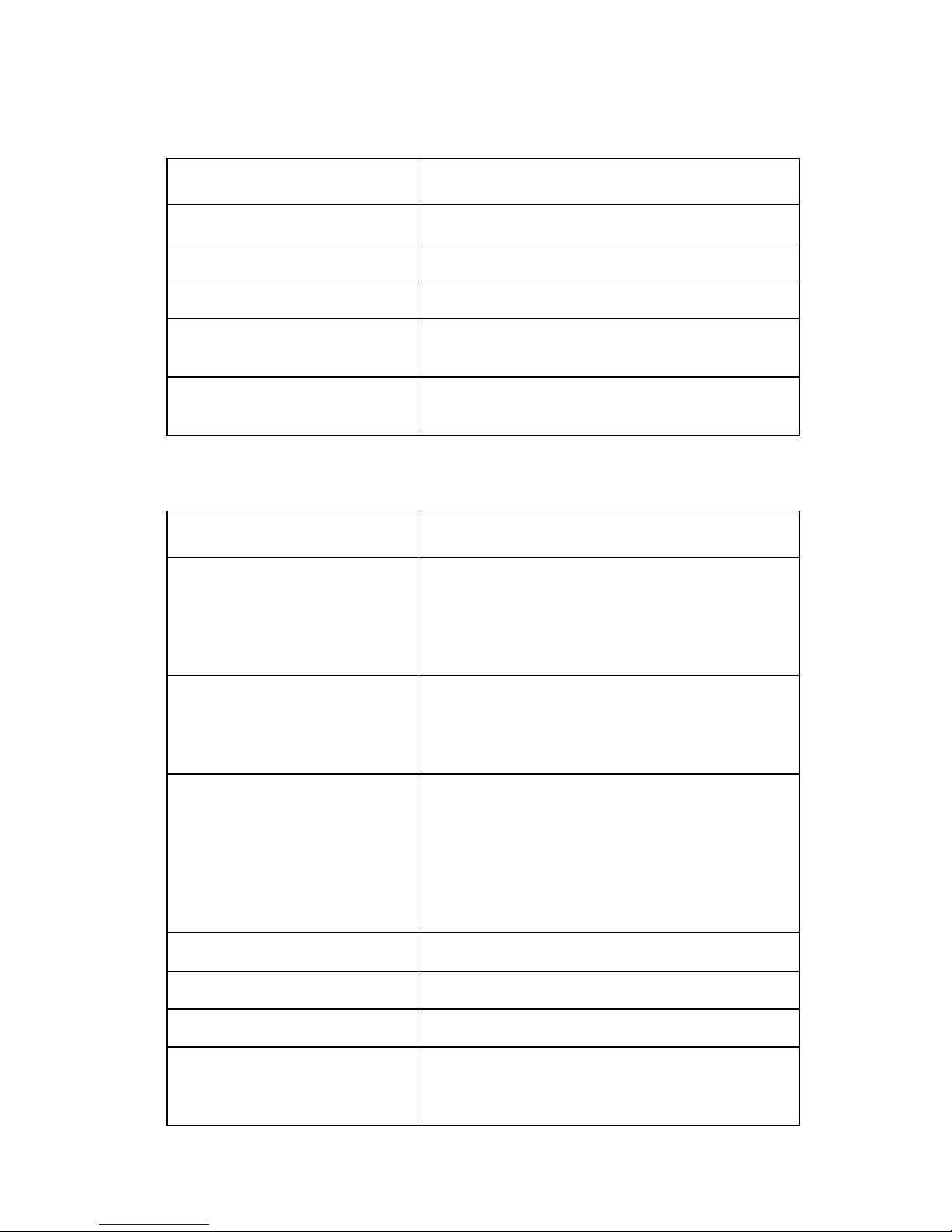
Setup menu options
Menu Function
Forms Macro options Customize macros to print a variety of forms.
Data options Define how informat ion is processed.
Control opt ions Define how the pri nter performs basic tasks.
Emulation options Determine how the printer interacts with
software appli cations.
Interface opt ions Define how informat ion is transferred fro m a
computer to the printer.
Interface menu options
Menu Function
Inte rf ac e • Autom a ti ca ll y s el e ct the pr in te r interfa c e .
• Use the parallel cable.
• Use the USB cable.
• Use the serial cable (onl y appears if
optional serial adapter is i nstalled).
Honor init • Enable honors the init signal on the
paralle l p or t.
• Disable ig nores the init signal on the
paralle l p or t.
Data speed • 300 bps
• 600 bp s
• 1200 bps
• 2400 bps
• 4800 bps
• 9600 bps
• 19200 bps
Data bits 7, 8
Parity No, Ignore, Odd, Even
Stop bits 1, 2
Protocol • XON/XOFF
• MultiXON/XOFF
•DTR Pacing
General information 1-3

25XX-100, -110
Printer settings
Setting the tear off position
When Auto T ear Off is on, or set to One Second, it moves the top
perforation of a continuous form to the tear off position, when all of
the following are true:
• The printer has finished printing.
• The paper has advanced to the Top-of-form on the next page.
• No data, printer control codes, or escape codes have been sent
to the printer after advancing to the Top-of-form.
• The print buffer has not received data for one second.
If you have already set Top-of-Form and now want to change the
tear off bar position, follow these steps:
1. Press Start/Stop to ta k e th e printer o ffline.
2. Press and hold Tear Off until the printer beeps.
3. Open the operator panel cover to access layer two.
4. Press Micro↑ or Micro ↓ to move the paper to the correct
position on the tear off bar.
5. Close the operator panel cover. The printer beeps twice. The
paper rolls backward, then goes to the new tear off position.
The Ready light is on.
The paper remains at the current tear off position until you send
another job to the printer. The paper moves from the tear off position
to the Top-of-form and begins printing.
1-4 Serv ice Manual

25XX-100, -110
Setting Top-of-form (continuous-pull mode)
1. Turn the printer on. The Paper Out light blinks if no paper is
loaded.
2. Move the Paper Select lever down to the continuous forms
position.
3. Load continuous form paper on the pull tractor feed pins.
4. Open the operator panel cover to access layer two.
5. Press any paper movement button (LineFeed, Micro↑, or
Micro ↓) to move the paper to the Top-of-form position.
6. Use the second sheet of continuous forms to set Top-of-form.
7. Press Set TOF to set and save Top-of-form.
8. Close the operator panel cover. Top-of-form is not saved if the
printer is turned off, or if it runs out of paper when the printer is
in Pull Tractor mode.
9. Press Start/Stop to set the printer online.
Setting Top-of-form (cut forms, envelopes)
Top-of-form can range from min us 1 to plus 22 inches from the top
of cut sheet paper. To set and save Top-of-form:
1. Turn the printer on. The Paper Out light blinks if no paper is
loaded. If the Paper Out light is off, tear off excess forms and
press Load/Unload. If an individual form is loaded, press
FormFeed to clear the paper path.
2. Move the paper select lever up to the cut forms position.
3. Load a cut sheet of paper or envelope through the manual feed
door. The printer moves the paper or envelope to the current
Top-of-form if Auto Cut Sheet is set to on. If not, press
FormFeed when the Paper Out light goes off.
4. Open the operator panel cover to access layer two.
5. Press any paper movement button (LineFeed, Micro↑, or
Micro ↓) to align the horizontal lines (located on the platen) with
the Top-of-form you want.
6. Press Set TOF to set and save Top-of-form.
7. Close the operator panel cover.
8. Press Start/Stop to set the printer online.
General information 1-5

25XX-100, -110
Printing a network setup page
If the printer is attached to a network, print a network setup page to
verify the network connection and find the printer address.
Note: This function is disabled if a USB cable is connected.
1. Make sure the printer is on and the paper is loaded.
2. With a paper clip or the tip of a pen, press the recessed button
located just above the Network connection.
3. Check the first section on the network setup page, and confirm
that the status is Connected. If the status is Not Connected,
the LAN drop may not be active, or the network cable may be
malfunctioning. See Network ing service check.
4. Check the network setup page to find the IP Address and the
Full y Qualified Do m a in N a m e . Th e Fu ll y Qualifie d D omain
Name is useful in situations where the Address changes. For
instance, the Address changes if the printer is moved; however,
the Fully Qualified Domain Name does not change.
Note: The network setup page also provides important network
configuration information.
1-6 Serv ice Manual

25XX-100, -110
Options
The 25XX printers support the following options:
• Automatic Sheet Feeder (ASF)
• Internal serial interface (RS232)
• OKI emulation (9 wire only)
• Tractor 2 sheet feeder
Tools
The basic tools necessary to service the 25XX printers are:
• Basic CE to ol kit
• #1 Phillips screwdriver
• #2 Phillips screwdriver
• Feeler gauges 0.33 mm (0.013 in.) and 0.37 mm (0.015 in.)
• Analog or digital volt-ohmmeter
General information 1-7

25XX-100, -110
Abbreviations
AFE Analog front end
ASF A uto matic sheet feeder
CPU Central processing unit
EPROM Erasable Programmable Read-Onl y Mem ory
ESD Electrostatic discharge
FRU Field replaceable unit
HTTP Hypertext transport protocol
HV High voltage
LED Ligh t em itting diode
LV Low voltage
MFP Multifunction Printer
mm Millimeter
NIC Network interface card
NVRAM Nonvolatile Random Access Memory
POST Power-On Self Test
RAM Random access memory
ROM Read-only storage
TCP/IP Transport control protocol/Internet protocol
USB Universal Serial Bus
V ac Volts alternating current
V dc Volts direct current
1-8 Serv ice Manual

25XX-100, -110
2. Diagnostic information
Start
Make a quick visual check for defects (loose or broken parts,
unplugged connectors, paper jams, and so on).
Voltage, ground, and continuity readings
V o ltage readings
All DC voltages must be within +5% through -10% of the values to
be considered correct. Unless stated otherwise, all connectors
should be connected normal ly when a voltage measurem ent is
performed.
When a “line voltage” measurement is to be performed, the voltage
on United States and Canada printers should be between 100 V ac
and 127 V ac. On World Trade printers, the voltage is according to
each country’s specification.
Ground checks
To check for a correct ground, measure the voltage between the
ground and a known good voltage source. The voltage
measurement must be the same as the source voltage to consider
that the ground is correct. Continuity measurements may be used to
check grounds; however, be sure to measure to a known good
ground using the lowest ohms scale and check for zero ohms.
Warning: Alway s unplug the power cord before doing any
continuity measurem ent.
Diagnostic information 2-1

25XX-100, -110
Cont inuity readings
When measuring continuity , be sure no back circuits affect the
measurement. If necessary , unplug connectors to remove any back
circuits. Zero the ohm range on the lowest scale (X1). An open
circuit will read infinity. A circuit with correct continuity will read zero
ohms.
2-2 Serv ice Manual

25XX-100, -110
Error indication table
The following table describes the service check entries for the
printer error indication codes.
When an error indication changes after you have entered a service
check, you have an intermittent problem. If this occurs, leave the
service check and go to “Symptom check table” on page 2-6.
LED Status Alarm Action
Power
Ready
Tractor 2
Paper Out
Panel Lock
Font Lock
Power
Ready
Paper Out
Panel Lock
Power
Ready
Paper Out
Font Lock
ON
ON
ON
ON
ON
ON
ON
Blinking
Blinking
Blinking
ON
Blinking
Blinking
Blinking
None POST
RAM, ROM Controller Error
Go to “POST service check” on
page 2-29.
None Switch Scan Test Error
Go to “Operator panel service
check” on page 2-23.
None NVRAM Read/Write Error
Turn the printer off and t hen back
on. If you get the same err or
during power-up , replace the logic
board and readjust the
bidirecti onal print adjust me nt. Go
to “ B i d ir ec t io n a l pr in t
adjustment” on page 4-4.
If the printer completes POST
successfully and eventuall y gets
the same error, go to
“Intermit tent problem service
check” on page 2-20.
Diagnostic information 2-3

25XX-100, -110
LED Status Alarm Action
Power
Ready
Paper Out
Panel Lock
Font Lock
Power
Ready
Trac tor 2
Paper Out
Font Lock
ON
Blinking
Blinking
Blinking
Blinking
ON
Blinking
Blinking
Blinking
Blinking
Beeps
10
times
None Home Position Err or Wit hout
None Ti mer Error
Home Position Error
Go to “Carrier service check”
on page 2-18.
Tract or 2 Home Position Error
If Tra ctor 2 is installe d, re mo ve it
to determine whet her the probl em
is with the Carrier Home Position
sensor or the T ractor 2 Home
Position sensor. See the
“Tractor 2 service check” on
page 2-36.
Alarm
Go to “Power service check”
on page 2-30.
Turn the printer off and the n back
on. If you get the same error
during po wer-up, repl ace t he logi c
board and readjust the
bidirectional print adjustment.
Power
Ready
Trac tor 2
Paper Out
Font Lock
ON
Blinking
Blinking
Blinking
Blinking
Go to “Bidir ecti onal print
adjustment” on page 4-4.
None Hardware Drive Error
The printhead or the printhead
cable(s) can cause this error. Go
to “Printhead service check”
on page 2-32.
Turn the printer off and the n back
on. If you get the same error,
replace the logi c board and
readjust the bidirectional print
adjustment. G o to “Bidirectional
print adjustment” on page 4-4.
If the printer completes POST
successfully and eventually gets
the sam e error, go to
“Intermittent problem service
check” on page 2-20.
2-4 Serv ice Manual

25XX-100, -110
LED Status Alarm Action
All LEDs OFF None Power Failure
Check the continuity of the power
cord and the volta ge of the user’s
outlet. If they are correct, go to
“Power service check” on
page 2-30.
Power
Tractor 2
Paper Out
Panel Lock
Font Lock
Any LED
on and
Power LED
off
The Power
LED blink s
or changes
intensity.
Power
Ready
Font Lock
ON
OFF
OFF
OFF
OFF
ON
Blinking
Blinking
None Operator Panel Failure
Go to “Operator panel service
check” on page 2-23.
None Go to “Operator panel service
check” on page 2-23.
None Go to “Power service check”
on page 2-30.
None Ether net option not installed. Go
to “Network service check” on
page 2-40.
Diagnostic information 2-5

25XX-100, -110
Sympto m ch eck tab le
1. Select the symptom that best describes the problem .
2. Perform the appropriate action before you go to the indicated
service check.
Abn o rma l indic a t ions
Symptom Action
7 or more lights tur n
on but do not turn
off.
The Power light is
on, but POST will
not run.
Disconnect the inte rface cable from the pri nter and
turn the printer of f and then back on. If POST now
runs correctly, the problem is in the computer or
interface cable.
Go to “POST service check” on page 2-29.
Abnormal noise pr oblems
Symptom Action
During POST,
abnormal noise
come s fr om the
carrier.
Duri n g idling,
abnormal noise
come s fr om the
printer.
Check the ribbon cartridge for binds or damage.
Go to “Carrier service check” on page 2-18.
Go to “Abnormal noise service check” on
page 2-15.
Abnormal noise
when feeding paper
Abnormal noise
during printing or
POST
2-6 Serv ice Manual

25XX-100, -110
Abnormal print operation problems
Symptom Action
Printer will not print,
or become ready.
Abnormal operation,
incorr ect char acter s,
or incorrect line
width
Printer is ready but
will not print from the
computer cor rectly.
Undefined or
incorrect
character(s)
Slow printi ng speed Go to “Print speed service check” on
Be sure the interf ace cable is connecte d properly.
Go to “No print or abnor mal print service
check” on page 2-23.
page 2-31.
Auto Sheet Feeder problems
Symptom Action
Auto Sheet Feeder
does not feed pap er.
Auto Sheet Feeder
double feed s.
Auto Sheet Feeder
has inter mitte nt feed
problems.
Be sure Sheet Feed is en abled i n the Set up mode .
Be sure the Paper Sel ect lever is in the cut sheet
position.
Go to “Auto Sheet Fe eder (ASF) ser vice chec k”
on page 2-16.
Diagnostic information 2-7

25XX-100, -110
Error indications
Symptom Action
Ready and Paper
Out lig h t s b lin k .
Paper Out and Font
light s blin k .
Turn the printer off and then back on.
Go to “Abnormal indi cations” on page 2-6.
Turn the printer off and then back on.
Go to “Irrecoverable operator errors” on
page 2-13.
Operator panel problems
Symptom Action
The Start/Stop
button does not
function, bu t no error
is indic at e d.
Only the Power light
turns on.
One or more buttons
do not function.
Turn the printer off and then back on.
Go to “Operator panel service check” on
page 2-23.
One or more lights
do not function.
2-8 Serv ice Manual

25XX-100, -110
Paper feed problems
Symptom Action
The Paper Out light
is blinking when
there is paper i n the
printer.
The Paper Out light
does not blink when
there is no paper i n
the printer and the
ASF is not installed.
Print operat ion starts
without paper.
The Load/Unload
button does not
function when the
push tractor is
installed.
Form fe ed length is
not correct.
The Load/Unload
button fu nctions
when cut sheets are
being used.
Go to “Paper Present se nsor s ervice check” on
page 2-24.
Be sure the paper present sensor is not blocked.
Go to “Paper Present se nsor s ervice check” on
page 2-24.
Be sure the Paper Select lever is in the correct
position.
Go to “Paper Select sensor service check” on
page 2-28.
Continuou s forms
feed, but cut sheets
fail to load.
Be sure the Paper Sel ect lever is in the cut sheet
position.
Verify that continuous forms have been parked
using the Load/Unload button.
Be sure Auto Cut Sheet is enabled in the Setup
mode.
Go to “Paper Select sensor service check” on
page 2-28.
Diagnostic information 2-9

25XX-100, -110
Symptom Action
The Load/Unload
button funct ions
when the pull tr actor
is insta lle d .
The Paper Out light
blinks, and the
FormFeed button
does not operate
until paper is locate d
at first print line.
Lower feed roll shaft
rotates, but paper
does not feed.
Pressing FormFeed
does not feed paper.
Abnormal noise
created while printer
is feeding.
Paper jams, skews,
or creases.
Be sure the Paper Select lever is in the tractor
position.
Go to “Pull Tractor sensor service check” on
page 2-34.
Be sure the Paper Select lever is in the correct
position.
Go to “Paper feed service check” on page 2-25.
Incorrect or no line
spacing: wider,
narrower, or
overlapping lines.
Push/Pull Tractor
does not work.
Incorrect Top-of form positioning.
Go to “Top-of-forms service check” on
page 2-35.
2-10 Service Manual
 Loading...