

Page 1

Lexium Servo Drive
17D Series
User Guide
Version 2.0 June 2003
31001643_K01_000_04
Page 2

Page 3
Preface
Preface The data and illustratio ns found in this bo ok are not bindi ng. We reserv e the right to
modify our products in line with our policy of continuous product development. The
information in this document is subject to change without notice and should not be
construed as a commitment by Schneider Electric.
Schneider Electric assum es no res po ns ibi lit y for any e rrors that m ay appe ar in this
document. If you have any suggestions for improvements or amendments or have
found errors in this publication, please notify us.
No part of this document may be reproduced in any form or by any means,
electronic or mechanical, including photocopying, without express written
permission of the Publisher, Schneider Electric.
CAUTION!
All pertinent state, regional, and local safety regulations must be observed when
installing and using this product. For reasons of safety and to assure compliance
with documented s ystem dat a, repai rs to c ompo nents shou ld be performed only by
the manufacturer.
Failure to observe this precaution can result in injury or equipment damage.
MODSOFT® is a registered trademark of Schneider Electric
The following are trademarks of Schneider Electric:
Modbus Modbus Plus Modicon 984 Quantum
DIGITAL® and DEC® are registered trademarks of Compaq Computer Corp.
IBM® and IBM AT® are registered trademarks of International Business Machines
Corporation.
Microsoft® and MS-DOS® and Windows® are registered trademarks of Microsoft
Corporation.
©Copyright 2003, Schneider Electric
890 USE 120 00 iii
Page 4

Preface
iv
890 USE 120 00
Page 5

Contents
Chapter 1 - Introduction 1
At a Glance...................................................................................................... 1
Document Scope ....................... ...... ...... ..... ...... ........................................ 1
What’s in this Chapter ............................................................................... 1
About this User Guide .................................................................................... 2
Who Should Use this User Guide ............................................................. 2
How this User Guide Is Organized ............................................................ 2
Related System Components ......................................................................... 4
Single-Axis Motion Control System ........................................................... 4
UniLink Commissioning Software for 17D ................................................ 4
Related Documentation .................................................................................. 5
Documents ................................................................................................ 5
Hazards, Warnings and Guidelines ................................................................ 6
Hazards and Warnings ............................................................................. 6
Additional Safety Guidelines ..................................................................... 9
Qualified Personnel ................................................................................... 9
Standards and Compliances ............................ ...... ........................................ 10
European Directives and Standards ......................................................... 10
EC Directive Compliance .......................................................................... 10
UL and cUL Compliance ........................................................................... 11
Conventions .................................................................................................... 12
Acronyms and Abbreviations .................................................................... 12
890 USE 120 00 v
Page 6

Contents
Chapter 2 - Product Overview 15
At a Glance...................................................................................................... 15
Introduction ............................................................................................... 15
What’s in this Chapter ............................................................................... 15
The 17D Series Servo Drive Family ............................................................... 16
Introducing the 17D Drive Family ............................................................. 16
Drives Available ..................................... ..... ...... ...... .................................. 16
Implementing the Drives ........................................................................... 16
Applicable Servo Motor Types .................................................................. 16
Connection to different mains supply networks ........................................ 17
Electrical Considerations .......................................................................... 18
17D Drive Family Portrait .......................................................................... 19
17D Drives Front View .............................................................................. 20
Equipment Supplied .................................................................................. 21
Equipment Available ................................................................................. 21
17D System Configuration Diagram ......................................................... 22
Overview of Usability Features........................................................................ 23
Digital Control ........................................................................................... 23
Usability Enhancements ........................................................................... 24
Restart lock -AS- (A00 drives only) ........................................................... 25
Overview of 17D Internal Electronics.............................................................. 26
17D Internal Electronics Block Diagram ................................................... 26
General Characteristics ............................................................................ 27
Primary Power .......................................................................................... 27
Bias Power ................................................................................................ 27
EMI Suppression ............................. ...... ..... ...... ...... .................................. 27
Internal Power Section .............................................................................. 28
DC Link Capacitor Reconditioning ............................................................ 28
Integrated Safe Electrical Separation .......................... ...... ..... ...... ...... ...... 28
LED display ............................................................................................... 29
Overview of System Software ........................................................................ 30
Setup ........................................................................................................ 30
Setting Parameters ................................................................................... 30
Automatic Card Recognition ..................................................................... 30
Default Settings ............................... ...... ..... ...... ........................................ 30
UniLink Commissioning Software ............................................................. 31
vi
890 USE 120 00
Page 7

Contents
Chapter 3 - Mounting and Physical Dimensions 33
At a Glance...................................................................................................... 33
What’s in this Chapter................................................................................ 33
Installation Safety Precautions ....................................................................... 34
Power Supply Overcurrent Protecti on .... ..... ...... ...... ..... ............................. 36
Earth Connections .................................................................................... 36
Cable Separation ...................................................................................... 36
Air Flow ..................................................................................................... 36
Drive Mounting and Physical Dimensions ...................................................... 37
17D Height, Width and Depth Dimensions ............................................... 37
17D Drive and Mounting Area Dimensions ............................................... 38
External Regen Resistor Assembly Dimensions ....................................... 39
External regen resistor assembly .............................................................. 40
Motor Choke Assembly Dimensions ......................................................... 41
Chapter 4 - Wiring and I/O 43
At a Glance...................................................................................................... 43
Introduction 43
What’s in this Chapter................................................................................ 44
Wiring and I/O Initial Considerations .............................................................. 45
Initial Considerations ................................................................................. 45
Grounding ................................................................................................. 45
Wiring Overview ............................................................................................. 46
Overview of 17D Wiring Connections ....................................................... 46
Connection diagram for LEXIUM 17D ....................................................... 47
Pin assignments for LEXIUM 17D ............................................................ 48
Cable Shield Connections .............................................................................. 49
Connecting Cable Shields to the Front Panel ........................................... 49
Cable Shield Connection Diagram ............................................................ 50
Power Wiring .................................................................................................. 51
AC Mains Power Supply Connection ........................................................ 51
Bias Supply Connection............................................................................. 51
Serial Power Connections.......................................................................... 52
External Regen Resistor Connection......................................................... 53
Regen Circuit Functional Description ........................................................ 53
Lexium BPH Servo Motor Connection (excluded BPH055) ...................... 54
Lexium BPH 055 Servo Motor Connection................................................ 55
890 USE 120 00 vii
Page 8

Contents
Lexium SER Servo Motor Connection ...................................................... 56
Servo Motor (with Optional Dynamic Brake Resistors and Contactor)
Connection................................................................................................ 57
Servo Motor Holding-Brake Control Functional Description ..................... 58
Signal Wiring .................................................................................................. 60
Lexium BPH Resolver Connection (excluded BPH055) ........................... 60
Lexium BPH055 Resolver Connection ..................................................... 61
Lexium SER Resolver Connection ........................................................... 62
Lexium BPH Encoder Connection ............................................................ 63
Lexium SER Encoder Connection ............................................................ 64
Incremental Encoder Emulation ............. ................................................... 65
Incremental Encoder Output Functional Description ................................ 65
SSI Encoder emulation ............................................................................. 66
SSI Encoder Output Functional Description ............................................. 66
Diagram of master-slave operation ........................................................... 67
Incremental encoder emulati on .............................................. ...... ...... ..... . 67
SSI encoder emulation ............................................................................. 67
External Incremental encoder connection ................................................ 68
External SSI encoder connection ............................................................. 69
Analog I/O Connection ................................................................................... 70
Analog Inputs .............................................. ...... ...... ..... ............................. 70
Servo Motor Rotation Direction ................................................................. 70
Analog Outputs ........................................... ...... ...... ..... ...... ..... .................. 71
Fault Relay and Digital I/O Connection .......................................................... 72
Digital Inputs and Outputs ........................................................................ 72
Using Functions Pre-programmed into the Drive ...................................... 73
Serial Communications Connection................................................................ 74
Serial Communications Connection Diagram ........................................... 74
CANopen Interface ................................................................................... 75
CAN bus cable ................................. ...... ................................................... 76
Stepper Motor Control Interface Connection................................................... 77
Stepper-Motor Control Interface Connection Functional Description ....... 77
Stepper-Motor Control Interface Connection Diagram ............................. 77
Stepper-Motor Speed Profile and Signal Diagram .................................... 78
viii
890 USE 120 00
Page 9

Contents
Chapter 5 - System Operation 79
At a Glance...................................................................................................... 79
What’s in this Chapter................................................................................ 79
Powering Up and Powering Down the System ............................................... 80
Power-on and Power-off Characteristics .................................................. 80
Stop Function ............................................................................................ 81
Emergency Stop strategies ....................................................................... 82
Wiring example ......................................................................................... 83
Description of the restart lock -AS- (MHDA••••A00 drives only) ..................... 84
Advantages of the restart lock .................................................................. 84
Description of the restart lock -AS- ................................................................. 85
Functional description ............................................................................... 85
Block diagram............................................................................................ 86
Signal diagram (sequence)........................................................................ 87
Installation / Commissioning...................................................................... 88
Connection diagram .................................................................................. 89
Application examples ................................................................................ 90
Control circuit example ................................................ ...... ..... .................. 91
Procedure for Verifying System Operation ..................................................... 92
Overview ................................................................................................... 92
Quick Tuning Procedure ........................................................................... 93
Parameter setting ...................................................................................... 95
Multi-axis system ....................................................................................... 95
Front Panel Controls and Indicators ............................................................... 96
Keypad Operation...................................................................................... 96
LED Display .............................................................................................. 97
Chapter 6 - Troubleshooting 99
At a Glance...................................................................................................... 99
What’s in this Chapter ............................................................................... 99
Warning Messages ......................................................................................... 100
Warning Identification and Description ..................................................... 100
Error Messages ........................................... ..... ...... ...... ..... ...... ....................... 101
Error Identification and Description............................................................ 101
Troubleshooting .............................................................................................. 105
Problems, Possible Causes and Corrective Actions ................................. 105
890 USE 120 00 ix
Page 10

Contents
Appendix A - Specifications 107
At a Glance...................................................................................................... 107
What’s in this Appendix ............................................................................ 107
Performance Specifications ............................................................................ 108
Performance Specifications Table............................................................. 108
Environmental and Mechanical Specifications ............................................... 109
Environmental Specifications Table .......................................................... 109
Mechanical Specifications Table .............................................................. 110
Electrical Specifications .................................................................................. 111
What’s in this Section ............................................................................... 111
Electrical Specifications - Power..................................................................... 112
Line Input Specifications Table ................................................................. 112
Bias Input Specifications Table ................................................................. 113
Limit supply values of the servodrive MHDA associated with a
BHP motor with brake .............................................................................. 113
External Fuse Specifications Table .......................................................... 114
Motor Output Specifications Table ............................................................ 115
Internal Power Dissipation Specifications Table ....................................... 116
Electrical Specifications - Regen Resistor ...................................................... 117
Regen Circuit Specifications ..................................................................... 117
Electrical Specifications - Signal .................................................................... 118
Motor Overtemperature Input Specifications Table .................................. 118
Resolver Input Specifications Table ......................................................... 118
Encoder Input Specifications Table .......................................................... 119
Emulated Encoder Output (Incremental Format) Specifications Table ..... 119
Encoder Output (Incremental Format) Timing Diagram ............................ 120
Encoder Output (SSI Format) Specifications Table .................................. 120
Encoder Input (Slave) Specifications Table .............................................. 121
Discrete Input Specifications Table .......................................................... 121
Discrete Output Specifications Table ........................................................ 122
Fault Relay Output Specifications Table ................................................... 122
Brake Output Specifications Table ........................................................... 122
Analog Input Specifications Table ............................................................ 123
Analog Output Specifications Table .......................................................... 123
Serial Communications Specifications Table ............................................ 124
Wire Specifications (Recommended) ............................................................. 125
Wire Specifications ................................................................................... 125
x
890 USE 120 00
Page 11

Contents
Appendix B - Parts List 127
At a Glance...................................................................................................... 127
What’s in this Appendix ............................................................................. 127
Lexium 17D Drives ......................................................................................... 128
Drives Available ........................................................................................ 128
External 24 Vdc supply ................................................................................... 129
External 24Vdc supply .............................................................................. 129
Drive Cables ................................................................................................... 130
Drive to Motor Cables ............................................................................... 130
RS-232 Serial Communications Cable Part Table .................................... 130
Encoder Output Cables Parts Table ......................................................... 130
Regen Resistor Assemblies ............................................................................ 131
Regen Resistor Assembly Part Table........................................................ 131
Servo Motor Choke.......................................................................................... 132
Servo Motor Choke Part Table (when cable length exceeds 25m)............ 132
Spare Parts ..................................................................................................... 133
Spare Parts Table ..................................................................................... 133
Appendix C - Drive-to-Controller Wiring Diagrams 135
At a Glance...................................................................................................... 135
What’s in this Appendix ............................................................................. 135
Typical Motion Controller Interface Connections ............................................ 136
Motion Controller Interface Diagram ......................................................... 136
Wiring a 17D Drive to Premium CAY Motion Modules ................................... 137
Premium CAY Single Axis Drive Option Diagram ..................................... 137
Premium CAY Multi-Axis Breakout Module Wiring Diagram ..................... 138
Premium CAY Multi-Axis and Breakout Module Diagram, First of 4 Axes. 139
Wiring a 17D Drive to a MOT 201 Motion Module .......................................... 140
MOT 201 Control Wiring Diagram ............................................................. 140
MOT 201 Encoder Wiring Diagram: Option 1 ........................................... 141
MOT 201 Encoder Wiring Diagram: Option 2 ........................................... 142
Wiring a 17D Drive to Quantum 140 MSx Motion Modules ............................ 143
Quantum 140 MSx Control and Encoder Wiring Diagram ........................ 143
890 USE 120 00 xi
Page 12

Contents
Wiring a 17D Drive to B885-11x Motion Modules .......................................... 144
B885-11x Control Wiring Diagram ............................................................ 144
B885-11x Encoder Wiring Diagram: Option 1 ........................................... 145
B885-11x Encoder Wiring Diagram: Option 2 ........................................... 146
Appendix D - Cable Connection Wiring Diagrams 147
At a Glance...................................................................................................... 147
What’s in this Appendix ............................................................................ 147
Wiring a Sub-D Connector with Shielding (drive side) .................................... 148
Wiring the Sub-D Connector .............................................. ..... .................. 148
Wiring the feedback connector of the motors ................................................. 150
Wiring the feedback connector of the BPH motors (excluded BPH055) ... 150
Wiring the feedback connector of the BPH055 motors ............................. 151
Wiring the feedback connector of the SER motors ................................... 152
Wiring the Motor Power Connector (Drive end).............................................. 153
Wiring the Motor Power Connector ................... ...... ..... ............................. 153
Wiring the BPH Motor Power Connector (excluded BPH055 )................... 154
Wiring the BPH055 Motor Power Connector ...................................... ...... 155
Wiring the SER Motor Power Connector ............................................ ..... . 156
Serial Communication Interface Connection (X6) RS 232 ............................. 157
Serial Communication Interface Cable Connectors .................................. 157
Appendix E - Servo Loop Diagrams 159
At a Glance...................................................................................................... 159
What’s in this Appendix ............................................................................ 159
17D Current Controller Overview ................................................................... 160
17D Current Controller Diagram................................................................ 160
17D Velocity Controller Loop .......................................................................... 161
17D Velocity Controller Loop Diagram ..................................................... 161
17D Analog Input Loop Diagrams................................................................... 162
Overview ................................................................................................... 162
17D Analog Input Mode 0 Loop Diagram.................................................. 162
17D Analog Input Mode 1 Loop Diagram ................................................. 163
17D Analog Input Mode 3 Loop Diagram.................................................. 164
17D Analog Input Mode 4 Loop Diagram ................................................. 165
17D Analog Input Mode 5 Loop Diagram ................................................. 166
xii
890 USE 120 00
Page 13

Contents
Appendix F - Expansion Options 167
At a Glance...................................................................................................... 167
What’s in this Appendix ............................................................................. 167
Expansion Cards ............................................................................................ 168
Overview ................................................................................................... 168
Fitting expansion card................................................................................ 168
I/O Expansion Cards ...................................................................................... 169
24 Vdc Discrete I/O Expansion Card......................................................... 169
IConnector and LED Location Diagram..................................................... 169
Light-Emitting Diodes (LEDs)..................................................................... 170
Terminal Assignments .............................................................................. 170
Controlling Pre-programmed Motion Tasks............................................... 172
Programming the PLC .............................................................................. 172
Motion Task Coordination.......................................................................... 172
Motion Task Application Examples ........................................................... 1 73
Example of a Motion Task Number............................................................ 173
Connection Diagram ................................................................................. 174
Appendix G - External Regen Resistor Sizing 175
At a Glance...................................................................................................... 175
What’s in this Appendix ............................................................................. 175
Overview ................................................................................................... 176
Determining When Energy Is Absorbed .................................................... 176
Determining External Regen Resistor Size..................................................... 177
Power Dissipation Calculatio n Proce dure .......................... ..... ...... ...... ..... . 177
Drive Energy Absorption Capability .......................................................... 178
Example Regen Resistor Power Dissipati on Ca lc ula tio n.......................... ..... . 179
Example Motor and Drive Specific ati ons ........................... ..... ...... ...... ..... . 179
Example Step 1...................... ..... ...... ...... ................................................... 180
Example Step 2 .......................... ...... ...... ..... .............................................. 181
Example Step 3 .......................... ...... ...... ..... .............................................. 181
Example Step 4 .......................... ...... ...... ..... .............................................. 182
Example Step 5 .......................... ...... ...... ..... .............................................. 182
Example Step 6 .......................... ...... ...... ..... .............................................. 182
Example Step 7 .......................... ...... ...... ..... .............................................. 182
Example Step 8 .......................... ...... ...... ..... .............................................. 183
890 USE 120 00 xiii
Page 14

Contents
xiv
890 USE 120 00
Page 15
Introduction
1
At a Glance
Document Scope This user guide contains complete installation, wiring interconnection, power
application, test and maintenance information on the Lexium 17D series servo
drive.
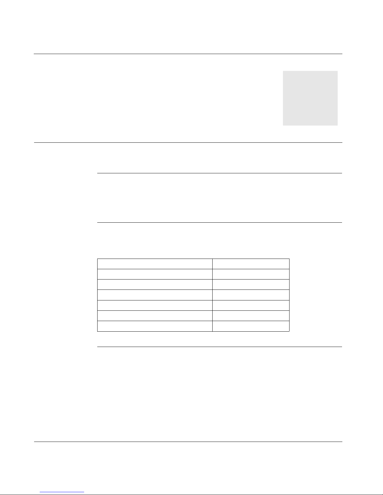
What’s in this
Chapter
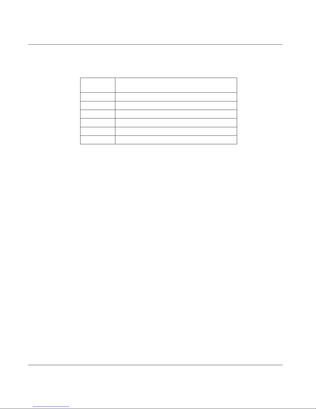
This chapter provides general information about this user guide and contains the
following topics:
Topic Page
About this user guide 2
Related system components 4
Related documentation 5
Hazards, warnings, and guidelines 6
Standards and compliances 10
Conventions 12
1
Page 16
About this User Guide
Who Should Use
this User Guide
This user guide is written for any qualified person at your site who is responsible for
installing (mounting and interconnecting), operating, testing and maintaining your
Lexium 17D servo drive and the servo system equipment with which it int erfaces. In
addition, the following precautions are advised:
l Transportation of the servo drive to, or from, an installation site should only be
performed by personnel knowledgeable in handling electrostatically sensitive
components.
l Commissioning of the equipment should only be performed by personnel
having extensiv e know ledg e of, and experi ence wi th, elec trical and se rvo dri ve
technologies .
Y ou a re expec ted to h ave some overall u nderst anding of what your 17D servo drive
does and how it will function in a high-performance, single-axis motion control
system. Accordingly, be sure you read and understand the general information,
detailed descriptions and associated procedures presented in this manual, as well
as those provided in other relevant manuals, before installing your 17D. (See
Related System Components
later in this chapter.)
If you have questions, please consult your Schneider Electric customer
representative.
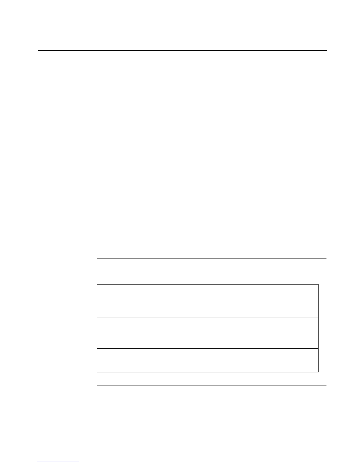
How this User
Guide Is
Organized
2
This manual is organized as follows.
Chapter/Appendix Description
Chapter 1
About this User Guide
Chapter 2
Lexium 17D Product Overview
Chapter 3
Mounting and Physical Dimensions
An introduction to this manual — who should use
this manual, how this manual is organized,
related publications, hazards and warnings.
General descriptions of the 17D servo drives,
descriptions of components that are supplied by
Schneider in a typical 17D system, and a block
diagram for internal electronics.
Physical dimensions and information for
mounting the servo drive, Regen resistor and
servo motor choke.
Continued on next page
Page 17
About this User Guide, cont inued
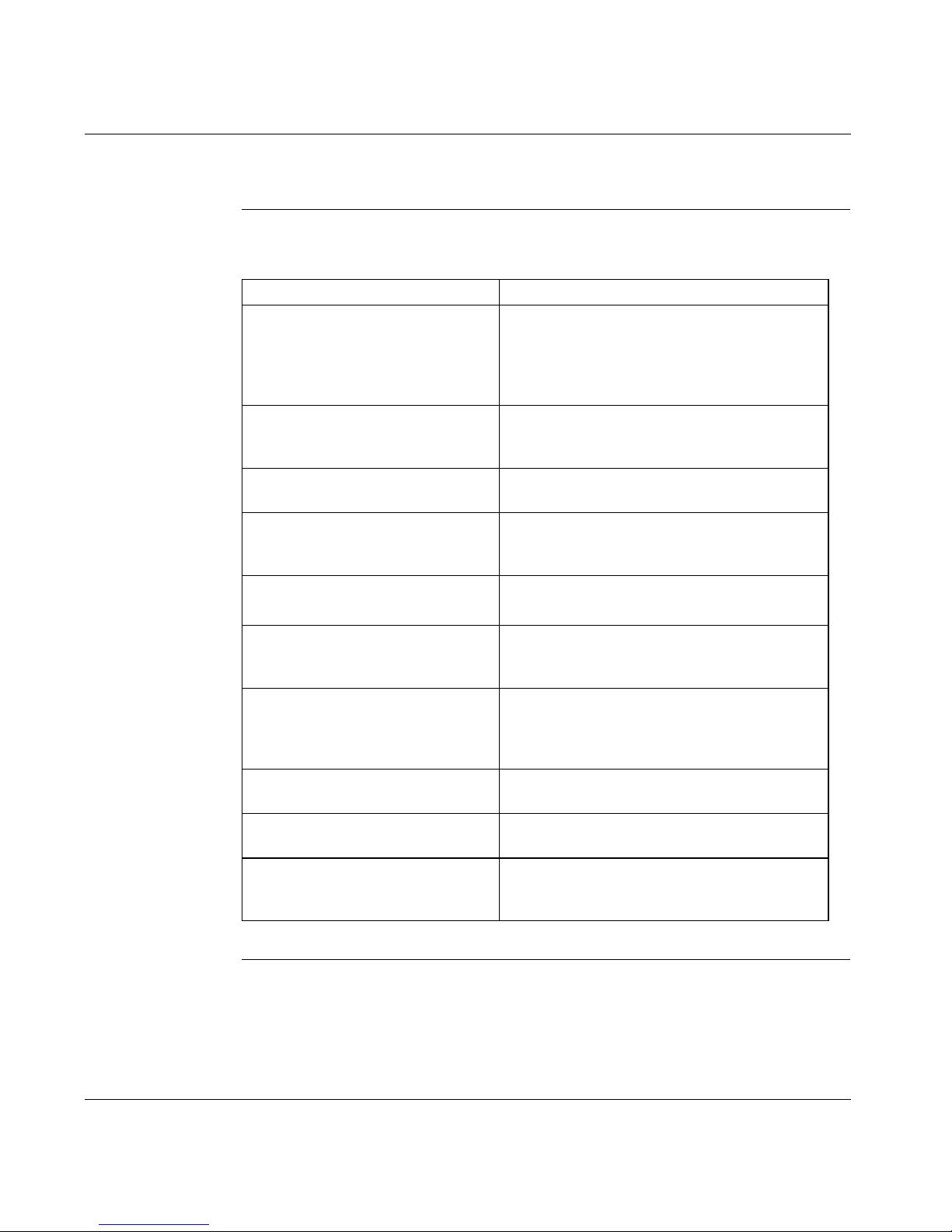
How this User
Guide Is
Organized,
continued
Chapter/Appendix Description
Chapter 4
Wiring and I/O
Chapter 5
System Initialization, Commissioning
and Operation
Chapter 6
Troubleshooting
Appendix A
Specifications
Wiring diagrams for the power connections and
wiring diagrams and descriptions for all signal
wiring connections — encoder, resolver, analog
I/O, discrete I/O, and serial communications
cable.
Detailed procedures and associated descriptions
on how to initialize, commission and operate a
typical 17D system.
Description of faults, probable causes and
recommended corrective actions.
Specifications for the servo drives, including
general, electrical, signal, and power
specifications.
Appendix B
Parts List
Appendix C
Drive to Controller Wiring Diagrams
Appendix D
Cable Connection Wiring Diagrams
Appendix E
Servo Loop Diagrams
Appendix F
Expansion Options
Appendix G
External Regen Resistor Sizing
Part numbers related to the 17D servo drive
system.
Wiring diagrams that show signal wiring between
a 17D servo drive and MOT 201, Quantum MSx,
B885-11x, and Premium CAY motion modules.
Procedures and associated diagrams that show
how to wire Sub-D and power cable connectors
as well as the serial communication cable used
with the drive.
Illustrations of the 17D servo drive and singleaxis motion module servo loops.
Description and procedure for using the I/O
expansion card with the drive.
Description and procedure for determining the
power dissipation requirement for the external
Regen resistor.
3
Page 18

Related System Components
Single-Axis
Motion Control
System
UniLink
Commissioning
Software for 17D
The 17D servo drive is typically only one component in a larger, single-axis motion
control system. A single axis comprises one motion module, one servo drive, and
one motor.
Compatible Schneider motion modules include:
l Quantum 140 MSx series motion modules
l Compact MOT 201 motion modules
l B885-11x series motion modules
l Premium CAY motion modules
To configure your single-axis system, you will be using the UniLink
axis
commissioning software, which Schneider supplies.
UniLink allows you to configure your 17D servo drive axis and tune the motor
quickly and easily. With its graphical user interface and oscilloscope tuning
features, UniLink provides an easy point-and-click method for configuring motion
setup parameters. UniLink minimizes or eliminates cumbersome programming
tasks.
For complete information on UniLink, please see the UniLink online help.
4
Page 19
Related Documentation
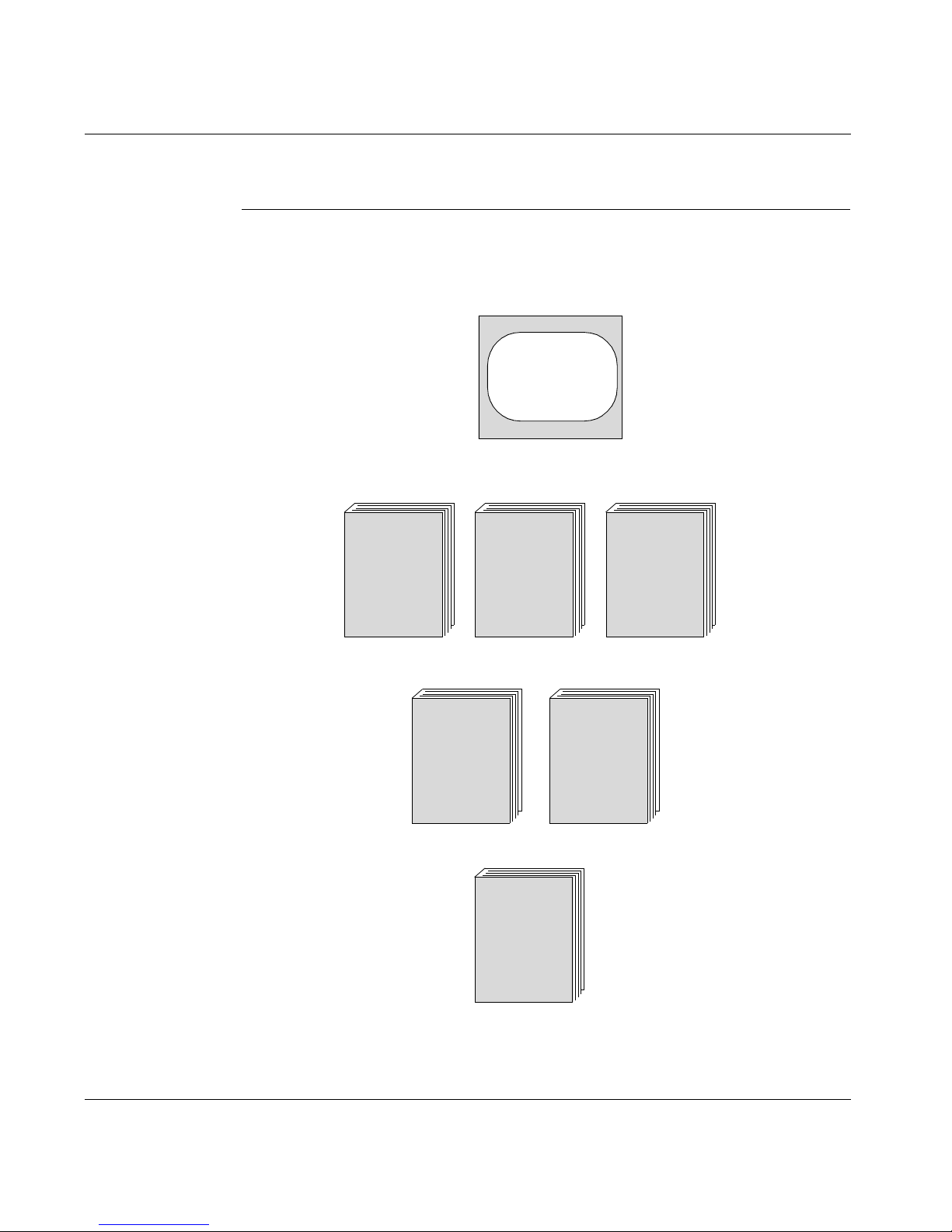
Documents Related documentation that covers all these system components is illustrated
below.
You will need these:
Unilink
Online Help
(included
in software)
Depending on which motion module you have, you will also need one of these:
MOT 201,
202 Motion
Modules
User Guide
GI-BMOT-20X
If you have a Premium motion module CAY, you will also need this:
PL7 Junior/Pro
Premium PLCs
Specific
Functions
TLX DS 57 PL7 40
If you have a BPH motor, you will also need this:
Quantum
140MSx 101
Single Axis
Motion
Module
Reference
Guide
840 USE 105 X
Premium PLCs
Installation
Manual
V4
TSX DM 57 40
Lexium BPH
Serie
servo motors
Motors Reference
Guide
B885-1xx
Motion
Modules
User Guide
GI-B885-1XX
* included in AM0 CSW 001V•00 (CDROM)
*AMOMAN001U
5
Page 20
Hazards, Warnings and Guidelines
Hazards and
Warnings
Read the following precautions very carefully to ensure the safety of personnel at
your site. Failure to c ompl y will re sult in dea th, seri ous in jury o r equipm ent da mage.
DANGER!
ELECTRIC SHOCK HAZARDS
l During operation, keep all covers and cabinet doors closed.
l Do not open the servo drives; depending on degree of enclosure protection,
the servo drives may have exposed components.
l Control and power connections on the drive may be energized even if the
motor is not rotating.
l Never attempt to disconnect the electrical connections to the servo drive with
power applied. Failure to comply may result in arcing at the contacts.
l Wait at least five minutes after disconnecting the servo drive from the mains
supply voltage before touching energized sections of the equipment (for
example, contacts ) or discon necting el ectrical con nections . Capacitors can st ill
have dangerous voltages present up to five minutes after switching off the
supply voltages. To ensure safety, measure the voltage in the DC Link circuit
and wait until it has fallen below 40V before proceeding.
l Check to ensure all energized connecting elements are protected from
accidental contact. Lethal voltages up to 900V can be present. Never
disconnect any electrical connections to the servo drive with power applied;
capacitors can retain residual and dangerous voltage levels for up to five
minutes after switching off the supply power.
Failure to follow any one of these instructions will result in death, serious
injury or equipment damage.
6
Continued on next page
Page 21

Hazards, Warnings and Guidelines, continued
WARNING!
THERMAL HAZARD
During operation, the front panel of the servo drive, which is used as a heat sink,
can become hot and may reach temperatures above 80°C. Check (measure) the
heat sink temperature and wait until it has cooled below 40°C before touching it.
Failure to observe this precaution can result in severe injury.
WARNING!
OVERCURRENT, OVERLOAD AND OVERHEATING PROTECTION
Separate motor overcurrent, overload and overheating protection is required to be
provided in accordan ce wit h the Ca nad ian Elec tric al Code, Part 1 and the National
Electrical Code.
Failure to observe this precaution can result in severe injury.
Continued on next page
7
Page 22
Hazards, Warnings and Guidelines, continued
CAUTION!
SAFETY INTERLOCKS
Schneider recommends the installation of a safety interlock with separate contacts
for each motor. Such a system sh ou ld be hard wired with over–travel lim it s w itc he s
and a suitable emergency stop switch. Any interruption of this circuit or fault
indication should:
l Open the motor contacts
l Shunt dynamic braking resistor s across each motor, if they are present.
Failure to observe this precaution can result in equipment damage.
CAUTION!
ELECTROSTATIC COMPONENTS
The servo drives contain electrostatically sens itive components that may be
damaged by improper handling. Appropriately discharge yourself before touching
the servo drive and avoid contact with highly insulating materials (artificial fabrics,
plastic film, and so on). Place the ser vo drive o n a conductive surface.
Failure to observe this precaution can result in equipment damage.
Continued on next page
8
Page 23

Hazards, Warnings and Guidelines, continued
Additional Safety
Guidelines
Qualified
Personnel
Read this documentation and adhere to the safety guidelines contained herein
before engaging in any activities involving the servo drives.
l Ensure that all wiring is in a ccorda nce with the Nati ona l Ele ctr ica l Code (NEC)
or its nationa l equiv alent (CSA, C ENELEC , etc.), as well a s in ac cordan ce wi th
all prevailing local codes.
l Exercise extreme caution when using instruments such as oscilloscopes, chart
recorders, or volt–ohm meters with equipment connected to line power.
l Handle the servo drives as prescribed herein. Incorrect handling can result in
personal injury or equipment damage.
l Adhere to the technical information on connection requirements identified on
the nameplate and specified in the documentation.
l The servo drives may only be operated in a closed cabinet or enclosure.
Nevertheless, operating co nditions must be always respected ( as defined
in Appendix A):
- operating temperature range
- pollution degree 2 as defined in EN 50178
- assembly.
Only properly qualified personnel having extensive knowledge in electrical and
servo drive technologies should install, commission and/or maintain the Lexium
17D servo drives.
9
Page 24

Standards and Compliances
European
Directives and
Standards
EC Directive
Compliance
The Lexium 17D servo drives are incorporated into an electrical plant and into
machinery for industrial use.
When the servo drives are built into machines or a plant, do not operate the servo
drive until the machine or plant fulfills the requirements of these European
Standards:
l EC Directive on Machines 89/392/EEC
l EC Directive on EMC (89/336/EEC)
l EN 60204
l EN 292
In connection with the Low Voltage Directive 73/23/EEC, the associated standards
of the EN 50178 series in conjunction with EN 60439-1, EN 60146 and EN 60204
are applied to the servo drives.
The manufacturer of the machine or plant is responsible for meeting the
requirements of the EMC regulations.
Compliance with the EC Directive on EMC 89/336/EEC and the Low Voltage
Directive 73/23/EEC is mandatory for all servo drives used within the European
Community.
10
The Lexium 17D servo drives were tested by an authorized testing laboratory and
determined to be in compliance wi th the directives identified above.
Continued on next page
Page 25

Standards and Compliances, continued
UL and cUL
Compliance
UL Listed (cUL Certified) servo drives (Underwriters Laboratories Inc.) comply with
the relevant American and Canadian standards (in this case, UL 840 and UL
508C).
This standard describes the minimum requirements for electrically operated power
conversion equipment (such as frequency converters and servo drives) and is
intended to eliminate the risk of injury to personnel from electric shock or damage
to equipment from fire. Conformance with the United States and Canadian
standard is determi ned by an i nde pe nde nt U L (cUL) fire inspector through the type
testing and regular checkups.
UL 508C
UL 508C describes the minimum requirements for electrically operated power
conversion equipment (such as frequency converters and servo drives) and is
intended to eliminate the risk of fire caused by that equipment.
UL 840
UL 840 describ es air a nd insu lation c reepage spacing s for ele ctrical equip ment and
printed circuit boards.
11
Page 26

Conventions
Acronyms and
Abbreviations
The acronyms and abbreviations used in this manual are identified and defined in
the table below.
Acronym or
Abbreviation Description
CE European Community (EC)
CLK Clock signal
COM Serial communication interface for a PC-AT
cUL Underwriters Laboratory (Canada)
DIN German Institute for Norming
Disk Magnetic storage (diskette, hard disk)
EEPROM Electrically erasable programmable read only memory
EMC Electromagnetic compatibility
EMI Electromagnetic Interference
EN European norm
ESD Electrostatic discharge
IEC International Electrotechnical Commission
IGBT Insulated Gate Bipolar Transistor
ISO International Standardization Organization
LED Light Emitting Diode
MB Megabyte
MS-DOS Microsoft Disk Operating System for PC-AT
PC-AT Personal computer in AT configuration
PEL V Protected extra low voltage
PWM Pulse-width modulation
RAM Random Access Memory (volatile)
Regen Regen resistor
RFI Radio Frequency Interference
12
Continued on next page
Page 27
Conventions, continued
Acronyms and
Abbreviations,
continued
Acronym or
Abbreviation Description
PLC Programmable Logic Controller
SRAM Static RAM
SSI Synchronous Serial Interface
UL Underwriters Laboratory
Vac Voltage, Alternating Current
Vdc Voltage, Direct Current
13
Page 28

14
Page 29
Product Overview
2
At a Glance
Introduction This chapter contains a product overview of the Lexium 17D series servo drives
and includes:
l Available drive models and related system components
l Feedback and performance information
l Power and signal electronics
l Software and axis configuration
What’s in this
Chapter
This chapter contains the following topics:
Topic Page
The 17D series servo drive family 16
Overview of usability features 23
Overview of 17D internal electronics 26
Overview of system software 30
15
Page 30
The 17D Series Servo Drive Family
Introducing the
17D Drive Family
Drives
Available
Each member of the Lexium 17D series family is comprised of a three-phase
brushless servo amplifier, power supply and high-performance digital controller all
housed in a single enclosure.
The 17D drives are available in five models which are correlated to different output
current levels as identified in the following table.
Output Current Intermittent (Peak) 17D Drive
4A
8A
17A
28A
56A
Note:
A00 means that restart lock -AS- is included.
N00 standard version
MHDA1004
MHDA1008
MHDA1017
MHDA1028
MHDA1056
•00
•00
•00
•00
•00
Implementing
the Drives
The Lexium 17D servo drives are intended for incorporation into electrical
equipment or ma ch ine r y a nd can only be commissioned as in tegral components of
those types of devices.
Applicable Servo
Motor Types
16
The Lexium 17D se rvo drives are intended to drive BPH and SER series brushless
servo motors.
Continued on next page
Page 31

The 17D Series Servo Drive Family, continued
Connection to
different mains
supply networks
On this page you’ll find all possible connection variations to different mains supply
networks.
WARNING !
An isolating transformer is always required for 400...480V mains networks
without earth(ground) and for networks with asymmetrical earth(ground).
208...230V
208...230V
208...480V
L1
L2
L3
PE
L1
L2
L3
PE
L1
L2
L3
PE
208V with 60Hz only
230...480V with 50Hz or 60Hz
1:1400...480V
1:1400...480V
L1
L2
L3
PE
L1
L2
L3
PE
208...230V
208...230V
208...230V
L1
L2
L3
PE
L1
L2
L3
PE
L1
L2
L3
PE
1:1400...480V
1:1400...480V
1:1400...480V
Continued on next page
L1
L2
L3
PE
L1
L2
L3
PE
L1
L2
L3
PE
17
Page 32

The 17D Series Servo Drive Family, continued
Electrical
Considerations
The Lexium 17D family of servo amplifiers is to be used on earthed three-phase
industrial mains supply networks (TN-system, TT-system with earthed neutral
point, not more than 5000 rms symmetrical amperes).
Periodic overvoltages between outer conductor (L1, L2, L3) and housing of the
servo amplifier ma y not exceed 1000V (peak value). Transient overvoltages (<
50µs) between the outer conductors may not exceed 1000V. Transient
overvoltages (< 50µs) between outer conductors and housing may not exceed
2000V.
The Lexium 17D drives are incompatible with the IT system because interference
suppression filters are inte rnal an d conne cted to earth. If th e user w ants to conne ct
Lexium drives to an IT system, he may:
l use an in sulation star trans former in order to re-create a local TT or TN s ystem.
This way allows the rest of the wiring to stay an IT system (only warning in
case of the first fault.)
l use a spec ial Residual C urrent Circ uit Breaker ( RCCB) that is able to w ork with
dc and high peak currents. This device detects unbalance of phases with
regard to earth.
Warnin g: W hen th e fi rst fau lt occ urs, the RCCB has to switch off qui ckly po w er
of the drives. Set of the res idual curren t val ue mu st be carefu lly d one an d mus t
be started with the lowest available value (for example: 30mA.)
Following equipment of Merlin Gerin can be used:
l Vigirex, model RH328AF (Reference: 50055)
18
l One of these magnetic cores:
- model TA, 30mm in internal diameter (Reference: 50437)
- model PA, 50mm in internal diameter (Reference: 50438)
- model IA, 80mm in internal diameter (Reference: 50439)
If the servo amplifiers are used in residential areas, or in business or commercial
premises, then additional filter measures must be implemented by the user.
The Lexium 17D family of servo amplifiers is only intended to drive specific
brushless sync hron ous s erv om otors from the Lexium BPH series , w ith c los ed -loo p
control of torque, speed and/or position. The dielectric withstand voltage of the
motors must be at least as hight as the DC-link voltage of the servo amplifier.
Use only copper wire. Wire size may be deter minate d from EN 60 204 (or table 3 1016 of the NEC 60°C or 75°C column for AWG size).
We only guarantee the conformance of the servo amplifiers w ith the standards for
industrial areas, if the component s (mot ors, cables , ampli fiers etc ) are del ivered by
Schneider Automation.
Continued on next page
Page 33

The 17D Series Servo Drive Family, continued
17D Drive Family
Portrait
The following photograph shows a representative member of the 17D drive family.
The complete family consists of five models partitioned into two physical sizes.
Models MHDA1004
have dimensionally identical physical housings while Model MHDA1056
wider housing. (See Chapter 3 for detailed dimensional information.)
•00, MHDA1008•00, MHDA1017•00 and MHDA1028•00
•00 has a
Model without AS function
Continued on next page
19
Page 34

The 17D Series Servo Drive Family, continued
17D Drives Front
View
The following photograph shows a typical 17D front view without AS function.
20
Continued on next page
Page 35

The 17D Series Servo Drive Family, continued
Equipment
Supplied
Equipment
Available
Each 17D servo drive includes the following har dware.
l Mating connectors X3, X4, X0
, X0B, X7 and X8
A
l Read me first.
l Mating connector X10 for AS functi on, de livere d only w ith MH DA••••A 00 drive s.
Note: The mating Sub-D connectors and servo motor connector X9 are supplied
with the appropriate cable.
The following items are optionally available to you from Schneider for use with the
17D servo drives:
l Lexium BPH series br ushless servo motors
l Servo motor power and feedback cables
Note: Power and feedback cables are available in lengths from 5...75 m and are
supplied by Schnei der w i th th e c onn ec tor fo r the se rvo mo tor a ttac he d to t he c ab le
and with the connector for the drive unasse mbled and un attached to the cable. The
10 m length cable is supplied (from stock) by Schneider with connectors attached
to each end of the cable.
l Optional S ervo motor choke (for motor power c able lengths exceeding 25m)
l Optional External Regen resistor
l Serial communications cable (between drive and PC)
l Pre-configured cables for various Telemecanique and Modicon motion
controllers.
l Optional expansion cards.
l Optional communication cards and accessories (SERCOS, MODBUS +,
FIPIO, PROFIBUS DP)
Continued on next page
21
Page 36

The 17D Series Servo Drive Family, continued
17D System
Configuration
Diagram
The following illustration shows a typical 17D system configuration.
22
Page 37

Overview of Usability Features
Digital Control The 17D drive provides complete digital control of a brushless servo system. This
includes:
l A digital field-oriented current controller operating at an update rate of 62.5 µs
l A fully programmable digital PI-type speed controller operating at an update
rate of 250 µs
l If required by user application, an integrated, digital, position controller with
configurable trajectory generation operating at an update rate of 250 µs is also
available. Up to 180 indep endent moti on tas ks c an be confi gured and s tored i n
the drive depending upon the application requirements.
l An integral step/direction input is provided for use with an external indexer
which al lows the 17D drive and the applicable BPH motor to be used as a
stepper motor/drive replacement.
l Full digital evaluation of motor position feedback (primary feedback) from
either a standard two-pole resolver or a high precision Sin-Cos type encoder
(hiperface).
l Full digital emulation of either a standard incremental encoder or a SSI
encoder is also available fr om positio n information derived from the primary
feedback device. The drive may also be configured as a slave to follow a
master incremental encoder with a programmable gear ratio.
Continued on next page
23
Page 38

Overview of Usability Features, continued
Usability
Enhancements
The following features are incorporated into the 17D drive to facilitate the set-up
and operation of the servo system:
l Two analog +/-10 V inputs can be programmed for a multitude of functions
depending upon the application. Both inputs incorporate automatic offset
compensation, dead-band limitation and slew-rate limitation.
l T wo +/-1 0 V analog mo nitor outpu ts can be programm ed to support a multitu de
of internal drive control loop variables via the analog voltage output levels.
l Four fully programmable 24 V discrete inputs; two of which are typically
defined as hardware limit swi tches.
l Two fully programmable 24 V outputs and a separate 24 V brake output
capable of driving a maximum of 2 Amps.
l An integrated and fully isolated RS-232 connection for communication with a
PC; used to set configur ati on par ameters and tune the system with the Unilink
configuration software.
l Integrated CANopen (default 500 kBauds)
l A separate 24V bias supply input which may be connected through a UPS to
preserve system data in the event of an interruption in the AC mains supply.
l Restart lock AS (A00 drives only).
24
Page 39

Overview of Usability Features, continued
Restart lock -AS(A00 drives only)
The restart lock -AS- is exclusively intended to provide safety for personnel, by
preventing the restart of a system. To achieve this personnel safety, the wiring of
the safety circuits must meet the safety requirements of EN60204, EN292
and EN 954-1.
The -AS- restart lock must only be activated,
l When the motor is no longer rotating
(setpoint = 0V, speed = 0rpm, enable = 0V).
Drives with a suspended load must have an additional safe mechanical
blocking (e.g. by a motor-holding brake).
l When the monitoring contacts (KSO1/2 and Fault RA/RB for all servo
amplifiers are wired into the control signal loop (to recognize a cable break).
The -AS- restart lock may only be controlled by a PLC if the control of the internal
safety relay is arranged for redundant monitoring.
The -AS- restart lock must not be used if the drive is to be made inactive for the
following reasons
l Cleaning, maint ena nc e and repai r opera tions
l Long inoperative periods
In such cases, the entire system should be disconnected from the supply by
the personnel, and secured (main switch).
l Emergency-stop situations.
In an emergency-stop situation, the main contactor is switched off (by the
emergency-stop button or the Fault RA/RB contact in the safety circuit).
25
Page 40

Overview of 17D Internal Electronics
17D Internal
Electronics
Block Diagram
The following block diagram illustrates the 17D internal electronics and depicts
internal interfaces for power, signal I/O, and communication.
LEXIUM
2
Analog1 in +
Analog1 in -
-AS-
Analog2 in +
Analog2 in -
-AS-
17D
-AS-
+Rb ext
+Rb int
- Rb
X10
KSI+
KSI-
KS01
KS02
26
X9
X2
-AS-
X1
-AS-
X9
Continued on next page
Page 41

Overview of 17D Internal Electronics, continued
General
Characteristics
The Lexium 17D servo drives are available in five peak output current ratings (4.2,
8.4, 16.8, 28 and 56 A) that are partitioned into two groups based on the width of
the package; the 70 mm drive s are rated to ha ndle cu rrents up to 28 A and the 120
mm wide drive is rate d to han dle current s up to 56 A. All Lexium drives o perate wi th
an input voltage which may range from 208 V -10% 60 H z , 230 V -10% 50 Hz
through 480 V +10% 50-60 Hz.
Each drive provides:
l Direct shield connection points
l Two analog setpoint inputs
l Integrated and electrically isolated RS-232 communications
Primary Power A single phase input supply may be used for commissioning and set-up and for
continuous operating with various smaller drive/motor combinations. See the
Lexium 17/ BPH motor torque speed curves for details.
Fusing (e.g. fuse cut-out) is provided by the user.
Bias Power The 17D drive requires 24 Vdc bias power from an external, electrically isolated
supply (SELV).
EMI Suppression EMI suppression for the 17D drives is integrally provided by filters on both the
primary power (EN550011, Class A, Group 1) input as well as on the 24 Vdc bias
supply (Class A) input.
Continued on next page
27
Page 42

Overview of 17D Internal Electronics, cont i nued
Internal Power
Section
DC Link
Capacitor
Reconditioning
The Internal power section of the 17D drive includes the following:
l Power input: A rectifier bridge directly connected to the three-phase earthed
supply system, integral power input filter and inrush current limiting circuit.
l Motor power output: PWM current-controlle d voltage sou rce IGBT -inv erter with
isolated current measurement
l Regen ci rcu it: D y nam ic d is trib uti on of Regen power between s ev eral drives on
the same DC Link circuit. An internal Regen resistor is standard; external
Regen resistors are available as required by your application.
l DC Link voltage: 300...700 V dc, nominal (900 Vdc, intermittent) and can be
operated in parallel.
If the servo drive has been stored for longer than one year, then the DC Link
capacitors will have to be reconditioned as follows:
Step Action
1 Ensure that all electrical connections to the drive are disconnected.
2 Provide 230 Vac, single-phase power to connector XO
L1 / L2) on the servo drive for about 30 minutes to recondition the
capacitors.
(terminals
A
Integrated Safe
Electrical
Separation
The 17D drive ensures safe electrical separation (in accordance with EN 50178)
between the power input/motor connections and the signal electronics through the
use of appropriate i ns ula tio n-c reep age dis tances and electrical isolation. Th e dri ve
also provides so ft-start cha racteri stics, o vervoltage a nd over temperatu re detectio n,
short-circuit protection and input phase-failure monitoring. When using BPH and
SER series servo moto rs in conjunction with Schneider’s pre-assembled cables,
the drive also monitors the servo motor for overtemperature.
28
Continued on next page
Page 43

Overview of 17D Internal Electronics, continued
LED display A three-character LED display on the front of the 17D drive indicates drive status
after the 24 Vdc bias supply is turned on. If applicable during operation, error and/
or warning codes are displayed.
29
Page 44

Overview of System Software
Setup Configuration software is used for setting up and storing the operating parameters
for the Lexium 17D series driv es. The dri ve is co mmissi one d with the as sista nce of
the UniLink software and, during this process, the drive can be controlled directly
through this software.
Setting
Parameters
You must adapt the servo drives to the requirements of your installation. This is
usually accomp lished by connect ing a PC (p rogrammin g unit) to th e drive’ s RS-2 32
serial interface the n runni ng the Schnei der-sup plied UniLink configu ration s oftw are.
The UniLink software and the associated documentation are provided on a CDROM. Use the UniLink software to alter parameter s; you can instantl y observe the
effect on the drive when there is a continuous (online) connection to the drive. In
addition, actua l values are simulta neously received from the drive and display ed on
the PC monitor.
During the configu ration p roc ess, th e Unili nk sof tware wi ll sho w the motors that are
correctly matched to the current rating of the drive being configured.
Automatic Card
Recognition
Any interface modu le s (exp ansio n cards) tha t may be built in to the drive or that you
install are automatically recognized by the drive’s internal firmware. Any additional
parameters required for position control or motion-block definition are made
available automatically in the UniLink configuration software.
Default Settings Motor-specific default settings for all the reasonable combinations of drive and
servo motor are incorpo rated into the drive’ s firmware. In mo st applicatio ns, you will
be able to use thes e default values to get your drive running without any problems.
(Refer to the UniLink online help for additional information on default values.)
30
Page 45

Overview of System Software, continued
UniLink
Commissioning
Software
The minimum PC system requirements needed for the UniLink commissioning
software are specified in the following table:
Item Minimum Requirement
Operating System Windows 95
Windows 98
Windows 2000
Windows ME
Windows NT 4.0
Hardware:
Processor
Graphics adapter
RAM
Hard drive space
Communications
486 or higher
VGA
8 Mbytes
5 Mbytes available
One RS-232 Serial Port
31
Page 46

32
Page 47

At a Glance
Mounting and Physical
Dimensions
3
What’s in this
Chapter
This chapter provides information on the mounting requirements for, and physical
dimensions of, the Lexium 17D series servo drives and includes the following
topics:
Topic Page
Installation safety precautions 34
Installation considerations 36
Drive mounting and physical dimensions 37
External Regen resistor mounting and dimensions 39
Choke mounting and dimensions 41
33
Page 48

Installation Safety Precautions
CAUTION!
MECHANICAL STRESS
Protect the drive from physical impact during transport and handling. In particular,
do not deform any exterior surfaces; doing so may damage internal components or
alter critical insulation distances.
Failure to observe this precaution can result in injury or equipment damage.
CAUTION!
ELECTRICAL STRESS
At the installatio n s ite , ensure the maximum permissi ble rate d v oltage at the Mains
and bias input connectors on the drive are not exceeded. (See EN 60204-1,
Section 4.3.1.) Excessive voltages on these terminals can result in destruction of
the Regen circuit and/or the drive’s electronics.
Failure to observe this precaution can result in injury or equipment damage.
CAUTION!
ELECTRICAL CONNECTIONS
Never disconnect the electrical connections to the servo drive while power is
applied.
Failure to observe this precaution can result in injury or equipment damage.
Continued on next page
34
Page 49

Installation Safety Precauti ons, continued
CAUTION!
CONTAMINATION AND THERMAL HAZARD
Ensure the 17D drive is mounted within an appropriately vented and closed
switchgear cabinet that is free of conductive and corrosive contaminants. Ensure
the ventilation clearances above and below the drive conform to requirements.
(Refer to Chapter 3 for additional information.)
Failure to observe this precaution can result in injury or equipment damage.
DANGER!
ELECTRIC SHOCK HAZARD
Residual voltages on the DC link capacitors can remain at dangerous levels for up
to five minutes af ter switchin g off the mains su pply volt age. Ther efore, meas ure the
voltage on the DC Link (+DC/-DC) and wait until the voltage has fallen below 40 V.
Control and power connections can still be energized, even when the motor is not
rotating.
Failure to observe these instructions will result in death or serious injury.
35
Page 50

Installation Considerations
Power Supply
Overcurrent
Protection
Earth
Y ou are responsible for prov iding over current protec tion (via circui t breakers and/ or
fuses) for the Vac mains supply and the 24 Vdc bias supply that are connected to
the drive.
Ensure the drive and associated servo motor are properly connected to earth.
Connections
Cable Separation Route power and control (signal) cables separately. Schneider recommends a
separation of at least 20 cm. This degree of separation improves the EMC
performance of the system. If a servo motor power cable includes wires for brake
control, those wires have a separate shield which must be connected to earth at
both ends of the cable.
Air Flow Ensure that there is an adequate flow of cool, filtered air into the bottom of the
switchgear cabinet co ntai ning the drive.
36
Page 51

Drive Mounting and Physical Dim ensions
17D Height,
Width and Depth
Dimensions
The following diagram shows height, width and depth dimensions for the 17D drive.
Model:
MHDA1004/00
MHDA1008/00
MHDA1017/00
MHDA1028/00
325 mm
Model:
MHDA1056/00
275 mm
m
m
*)
3
7
2
(
5
6
2
7
0
m
m
5
6
2
m
m
)
*
3
7
2
(
275 mm
325 mm
1
2
0
m
m
* Dimensions with mating connectors installed
Continued on next page
37
Page 52

Drive Mounting and Physical Dimensions, continued
17D Drive and
Mounting Area
Dimensions
The following diagram shows depth dimensions and mounting area requirements
for the 17D drive.
Cable duct
45 mm 5 mm 305 mm
50 mm
00
/
MHDA1056
45 mm
00
/
MHDA1056
40 mm70 mm70 mm70 mm40 mm
00
/
MHDA1004
00
/
MKDA1008
00
/
MHDA1017
00
/
MHDA1028
00
/
MHDA1004
00
00
/
/
MKDA1008
MHDA1017
Cable duct
00
/
MHDA1028
38
Cabinet door
2,5 mm
(min.)
273 mm
Mounting panel
265 (273 mm*) mm
M5
Lexium 17D
* Dimensions with mating connecto rs installed
Page 53

External Regen Resistor Mounting and Physical Dimensions
External Regen
Resistor
Assembly
Dimensions
The following diagram shows the dimensions for all three external Regen resistor
assemblies.
F
E
A
B
C
E
D
+Rb
-Rb
PE
ext
G
Regen Resistor
Assembly
Part Number
ext
AM0RFE001V025
AM0RFE001V050
AM0RFE 001V150
Power
R
Ω
33
33
1500
33
A B C D E F G Weight
mm mm mm mm mm mm mm Kg
W
342 352 410 64 45 4,8 x 8 77 1,5
250
413 428 485 93 64 6,5 x 12 120 4, 0
600
513 528 585 186 150 120 8,0
6,5 x 12
39
Page 54

External Regen Resistor Mounting and Physical Dimensions, continued
External regen
resistor
assembly
CAUTION !
Surface t emperature can
exceed 20 0°C. Observe
the requested free s pace.
Do not moun t on
combustible material !
100
Air flow
60
3030
40
Page 55

Motor Choke Mounting and Dimensions
3
Motor Choke
Assembly
Dimensions
The following diagram shows the dimensions for the motor choke assembly.
250
153.3
62
160
35
113
4.
N.B. : All dimensions are in millimeters
(mm).
35
Réf. Irms max. F max. L
AM0FIL001V056
3 x 20 A 8.3 kHz 1,2 mH
155
M4
41
Page 56

42
Page 57

Wiring and I/O
4
At a Glance
Introduction This chapter describes and illustrates all power wiring connections, all signal wiring
connections, an d I/O wi rin g co nne ctions on the 17D drive. Power and signal wir ing
connections are:
l AC mains power through a 4-position, plug-in, terminal block connector, X0
l Bias power through 4-position, plug-in, terminal block connector, X4
l Servo motor power throug h a 6-pos ition, plug-in, term inal bl ock conne ctor, X9
l Optional Regen power resistor through a 4-position, plug-in, terminal block
connector, X8
l Resolver feedback input through a 9-pin, plug-in, Sub-D connector, X2
l Encoder feedback input through a 15-pin, plug-in, Sub-D connector, X1
l Auxiliary encoder/command interface through a 9-pin, plug-in, Sub-D
connector, X5
l Master-Slave drive interface through a 9-pin, plug-in, Sub-D connector, X5
l Analog/digital I/O through an 18-position, plug-in terminal block connector, X3
l Serial communications interface through a 9-pin, plug-in, Sub-D connector,
X6
l Stepper-motor control interface through an 9-pin, plug-in, Sub-D connector,
X5
l Restart lock through a 4-position, plug-in, terminal block connector, X10 (A00
drives only)
Continued on next page
A
43
Page 58

At a Glance, continued
What’s in this
Chapter
This chapter contains the following topi cs.
Topic Page
Wiring and I/O initial considerations 45
Wiring overview 46
Cable shield connections 49
Power wiring 51
Signal wiring 60
Analog I/O connections 70
Fault Relay and Digital I/O connections 72
Serial communications connections 74
Stepper-motor control interface connections 77
44
Page 59

Wiring and I/O Initial Consider ations
Initial
Considerations
Some descriptions and illustrations contained in this chapter are provided as
examples. Actual implementation depends on the application of the equipment;
thus, appropriate variations are allowed provided they neither violate any safety
precautions nor jeopardize the integrity of the equipment.
DANGER!
ELECTRIC SHOCK HAZARD
Before you wire and connect cables, ensure the mains po wer supply, the 24 Vdc
bias power supply and the power supplies to any other connected equipment, are
OFF. Ensure any cabinet to be accessed is first electrically disconnected, secured
with a lock-out and tagged with warning signs.
Failure to observe these safety instructions will result in death or serious
injury.
Grounding Ensure the drive mounting plate, servo motor housing and Analog Com for the
controls are connected to common panel earth ground point.
Continued on next page
45
Page 60

Wiring Overview
Overview of 17D
Wiring
Connections
The following diagram shows the wiring connections for the 17D drive.
CAUTION:
Do not connect a Modbus serial port to the X6 connector!
Pin1 carries +8 Vdc which would be shorted out by a Modbus cable.
Instead, use a 3-core cable (not a null-modem link cable) with only
pins 2, 3 and 5 wired.
Failure to observe this precaution can result in equipment damage.
X0A, X0
B -
Note: The connectors descri bed above appea r in many wiring diagrams throug hout
the remainder of this document and are identified in those diagrams by their
alphanumeric designations only (for example, X4); the term
46
X0
A
X0
B
connector
is excluded.
Continued on next page
Page 61

Connection
diagram for
LEXIUM 17D
Reference Safety Instructions
and Use As Directed!
Sine-Cosine
Encoder
Resolver
M
Remove jumper if external
regen resistor is connected
Regeneration
resistor
Max. 10A
Master
contactor
thermal control
included
thermal control
included
U2
V2
W
PE
B+
B-
F
B1
FB2
FN1
FN2
FN3
supply unit
24Vdc
FH1
H
F
15
8
X1
high
resolution
single /
multiturn
X2
Resolver
6
U
5
V
4
W
3
P
2
Brake+
1
Brake-
2
+RBint
1
-RB
3
+R
4
n.c.
1
L1
2
L2
3
L3
4
1
2
+24 Vdc
3
24 Vdc Com
4
L1 L2 L3 PE
1234 1234
X9
X8
Bext
X0A
PE
X4
X0B
Analog 1in +
Analog 1 in -
Analog Com
Analog 2 in +
Analog 2 in Analog Out 1
Analog Com
Analog Out 2
X3
I/O Com
Output 1
Output 2
Fault RA
Fault RB
X5
X6
X7
DC+ DC+DC- DC-
Input 3
Input 4
Input 1
Input 2
Enable
ROD
SSI
Ma./SI.
Pulse
CAN
PC
18
13
16
14
11
12
15
17
10
4
5
1
6
7
8
9
2
3
3
3
PE-connection (protective earth)
earth connection (panel)
shield connection via plug
shield connection at the front panel
+/-10V speed
setpoint1
referenced to GND
GND
+/-10V speed
setpoint2
referenced to GND
Analog 1
GND
Analog 2
GND
I/O-GND
+24V referenced
to 0V/GND
Digital1
Digital2
Safety
circuit
encoderevaluation,
stepper motor control,
slave/master
amplifier
Can-Master
COM1/COM2
PEL1 L2 L3
shielding if cable
is longer than 20cm
to other amplifiers
47
Page 62

Wiring Overview, continued
Pin assignments
for LEXIUM 17D
X6 PC/CAN X1 ENCODER
X2 RESOLVERX5 ROD/SSI
pulse-direction
master-slave
1 Reserved
2 RxD
Analog Com 1
Fault Ra 2
Fault Rb 3
Analog 1 In+ 4
Analog 1 In- 5
Analog 2 In+ 6
Analog 2 In- 7
Analog Out 1 8
Analog Out 2 9
Analog Com 10
Input 1 11
Input 2 12
Input 3 13
Input 4 14
Enable 15
Output 1 16
Output 2 17
I/O Com 18
KSO1 1
KSO2 2
KSI - 3
KSI+ 4
+24Vdc 1
+24Vdc 2
+24Vdc Com 3
+24Vdc Com 4
3 TxD
4 N.C.
7
8
CANL 6
X3
X10
X4
5 PGND
CANH 9
1 Pcom
2 M+
3 M-
B+ (DATA) 6
B- (/DATA) 7
4 A or CLK
5 A or CLK
N.C. 9
Reserved 8
B
0
X
5 R1
4 S2
3 S321 Shield
S4 8
R2 9
V
S1 7
V 6
V
8 Clock7 6 N.C.
5 DATA(+485)
14
V
Clock 15
Up SENSE 12
DATA (-485) 13
4 Up (8V)
3 B+ (COS)
2 0V(GND)
1 A+ (SIN)
0V SENSE 10
A- (REFSIN) 9
B- (REFCOS) 11
View: looking at the
face of the built-in
connectors
e
k
a
br
/
or
ot
m
9
X
e+
N
E
G
E
R
8
X
T
X
.
E
c
B
nt
i
n.
R
B
+
4
R
B
+
3
R
-
2
E
P
1
L3
4
2
L
3
1
L
2
1
A
0
X
3
2
1
2
L
1
L
c
r
i
c
-
C
D
7
X
2
1
4
C
D
E
+
P
L3
E
e-
ak
r
ak
B
r
B
2
1
t
ui
4
3
DC
C
-
D
C
+
D
-
2
U
2
2
V
6
W
5
P
4
3
Coding
48
Page 63
Cable Shield Connections
Connecting
Cable Shields to
the Front Panel
The following procedure and associated diagram describe how to connect cable
shields to the front panel of the 17D drive:
Step Action
1
2
3
4
5
Remove a length of the cable’s outer covering and braided shield sufficient to
expose the required length of wires.
Secure the exposed wires with a cable tie.
Remove approximately 30 mm of the cable’s outer covering while ensuring the
braided shield is not damaged during the process.
At the front panel of the drive, insert a cable tie into a slot in the shielding rail.
Use the previously inserted cable tie to secure the exposed braided shield of
the cable firmly against the shielding rail.
Continued on next page
49
Page 64

Cable Shield Connections, continued
Cable Shield
Connection
Diagram
The following diagram shows the cable shield connections at the front of the 17D
drive.
Cable tie
1
30 30
Cable tie
4
32
D
7
1
ium
x
e
L
50
Cable tie
5
D
7
1
m
u
i
x
e
L
Page 65

Power Wiring
AC Mains Power
Supply
Connection
Bias Supply
Connection
The following diagram shows the connections for the AC mains power supply input
to the 17D drive.
Lexium 17D
XO
A
1
L1
2
L2
3
L3
4
PE
FN1
FN2
FN3
PE
Three phase
L1
50Hz
230... 480 Vac*
L2
Three phase
60Hz
208... 480 Vac*
L3
208...230V
60Hz
208...480V
60Hz
208...230V
60Hz
230...480V
50Hz
*3 x 230 V +10% max. with a BPH055 Servo motor
The following diagra m shows the connectio ns for the bias power su pply input to the
17D drive.
External 24 Vdc
supply (SELV)
+
-
FUS
L1
L2
PE
+24 V
Lexium 17D
33V
X4
1
2
3
+24 Vdc
+24 Vdc
(1)
Com +24 Vdc
(1)
The current must not exceed 10A through these pin.
4
Com +24 Vdc
(
1
)
Continued on next page
51
Page 66

Power Wirin g , continued
Serial Power
Connections
The following diagram shows the serial connections for the AC mains and bias
power among multiple 17D drives.
AC supply
Lexium 17D
X4
+24
+24
COM
COM
X0A
L1
L2
L3
PE
X7
+DC
-DC
+DC
-DC
X0B
L1
L2
L3
PE
3
3
To
Next
Drive
L1
L2
L3
~
=
3
3
Lexium 17D
X4
+24
+24
COM
COM
X0A
L1
L2
L3
PE
X7
+DC
-DC
+DC
-DC
X0B
L1
L2
L3
PE
Lexium 17D
X4
3 3
+24
+24
COM
3
COM
X0A
L1
L2
L3
PE
X7
+DC
-DC
+DC
-DC
X0B
L1
L2
L3
PE
3
DC supply
3
3
Lexium 17D
X4
+24
+24
COM
COM
X0A
L1
L2
L3
PE
X7
+DC
-DC
+DC
-DC
X0B
L1
L2
L3
PE
3
NC
3
To
Next
Drive
POWER
SUPPLY
+DC
-DC
24 Vdc
Power Supply
3
3
1
2
Fuse
Max fuse: 20 A
1
schielded if length > 20 cm
2
Max. 10 A
3
Lexium 17D
X4
+24
+24
COM
COM
X0A
L1
L2
L3
PE
X7
+DC
-DC
+DC
-DC
X0B
L1
L2
L3
PE
NCNC
Notes: -Inrush current must be limited to 20 A between power supply and drives.
- Drives have to be configured (see Unilink commands) to suppress faults.
52
Continued on next page
Page 67

Power Wiring, continued
e
e
External Regen
Resistor
Connection
Regen Circuit
Functional
Description
The following d iag ram s ho w s the c onnections between the exte rnal Re gen resistor
and the 17D drive. The drive is shipped with a jumper installed on connector X8,
terminals R
and R
B
. If you are going to use an external Regen resistor, then
Bint
remove the jumper to disconnect (and thus disable) the internal Regen resistor
Fusing of the two lines to external Regen Resistor is mandatory.
X8
-RB
+RBint
+RBext
N.C.
If using an external Regen resistor, disabl
the internal Regen resistor by removing th
jumper between -RB and +RBint.
FB1
RBext
FB2
Use high voltage AC/DC and fast fuses..
Lexium 17D
Bint
1
2
3
4
-DC
+DC
R
During braking, energy from the se rvo mo tor is returned to the drive and converted
into heat in the Regen resistor. Operation of the Regen resistor is controlled by the
Regen circuit using thresholds that are adjusted to the main supply voltage that is
configured in the UniLink software. The following is an abbreviated functional
description of the Regen circuit operation.
l Individual drive (not coupl ed thro ugh the DC Li nk c ircuit) - The c ircuit starts to
respond at a DC Link voltage of 40 0V, 720V or 840V (depending on the supply
voltage). If the energy fed back from the servo motor is higher than the preset
Regen power, then the drive issues a "Regen power exceeded" signal and the
Regen circuit will be switched off. Upon the next internal check of the DC Link
voltage, an overvoltage will be detected, the fault relay contact will be opened
and the drive will be switched off with the error message "Overvoltage".
l Multiple drives (co up led thro ug h th e D C Lin k c irc ui t) - In t his c as e, the R ege n
energy is distributed equally among all the drives.
Continued on next page
53
Page 68

Power Wirin g , continued
Lexium BPH
Servo Motor
Connection
(excluded
BPH055)
The following diagrams show the connections between a servo motor (excluded
BPH055) and the 17D drive. When the interface cable length exceeds 25 m, a
motor choke must be in stalled as shown and at a distance of one meter or less from
the drive.
Connection between servo motor and drive when interface cable length is 25 m or less.
LEXIUM 17D
X9
24 Vdc Com
24 Vdc
Connection between servo motor and drive when interface cable length exceeds 25 m..
LEXIUM 17D
24 Vdc Co m
24 Vdc
1
2
3
4
5
6
X9
1
2
3
Brake- (Black)
Brake+ (White)
Gnd (Green)
W2 (3)
V2 (2)
U2 (1)
Motor Choke
AMOFIL001V056
B-
B-
B+
B+
PE
PE
Brake -
(Black)
Brake +
(White)
Gnd
(Green)
Servo
Motor
Note : The choke must be installed at a distance of one meter or less from the drive.
54
W
V1
U1
W
V2
U2
4
5
6
W2 (3)
V2 (2)
U2 (1)
Servo
Motor
Continued on next page
Page 69

Lexium BPH 055
Servo Motor
Connection
The following di agra ms show the connections betwe en a BPH055 servo motor and
the 17D drive. When the interface cable length exceeds 25 m, a motor choke must
be installed as shown and at a distance of one meter or less from the drive.
Connection between servo motor and drive when interface cable length is 25 m or less.
LEXIUM 17D
X9
24 Vdc Com
1
5
Brake -
24 Vdc
2
3
4
5
6
4
Gnd (Green)
2
3
1
Brake +
BPH055
Servo
Motor
Connection between servo motor and drive when interface cable length exceeds 25 m..
24 Vdc
LEXIUM 17D
24 Vdc Com
X9
1
2
3
4
5
6
Motor choke
AMOFIL001V056
B-
B-
B+
B+
PE
PE
W1
W2
V1
V2
U1
U2
5
4
Gnd
(Green)
2
3
1
BPH055
Servo
Motor
The choke must be installed at a distance of one meter or less from the drive.
Note :
WARNING!
With a BPH055 Servo motor, power supply of the 17D drive must be limited to
3 x 230 Vac +10%
Continued on next page
55
Page 70

Power Wirin g , continued
Lexium SER
Servo Motor
Connection
The following diagrams show the conn ect ion s between a SER servo motor and the
17D drive. When the interface cable length exceeds 25 m, a motor choke must be
installed as shown and at a distance of one meter or less from the drive.
Brake - (Grey)
Brake + (White)
Gnd (Green)
L1
L2
L3
SER
Servo
Motor
56
(Grey)
L1
SER
Servo
L2
L3
Motor
Note: The choke must be installed at a distance of one meter or less from the drive.
Continued on next page
Page 71

Power Wiring, continued
Servo Motor
(with Optional
Dynamic Brake
Resistors and
Contactor)
Connection
The following diagram shows the connections between a servo motor and the 17D
drive when the optional dynamic brake rersistors and associated contactor are
incorporated.
LEXIUM 17D
24 Vdc
Com 24 Vdc
X9
1
2
3
4
5
6
RB RB
Brake -
Brake+
Gnd
(Green)
W2
V2
U2
Servo
Motor
10
Continued on next page
57
Page 72

Power Wirin g , continued
Servo Motor
Holding-Brake
Control
Functional
Description
A 24V holding brake in the servo motor is controlled directly by the 17D drive
through software-selectable BRAKE parameter settings. The time and functional
relationships between the ENABLE signal, speed setpoint, speed and brak ing force
are shown in the following diagram.
.
Speed
Setpoint
Input
ENABLE
Input
Internal
Speed
Setpoint
Actual
Speed
ENABLE
Internal
BRAKE
Output
V
V
V
S
V
V
3%
10ms
Ramp +
100ms
t
t
t
t
t
58
t
t
Bracking
Force
F
t
SET t RELEASE
During the fixed ENABLE delay time of 100 ms, the internal speed setpoint of the
drive is internally driven down a 10 ms ramp to 0 V. The 3 % region of actual speed
is scaled to V
LIM
.
Note: The set and re lease times o f the ho lding brake vary wi th the s ervo mot or and
thus must be considered when setting parameters.
Continued on next page
Page 73

Power Wiring, continued
WARNING!
IMPACT HAZARD
The off-the-shelf configuration of the holding-brake function does not ensure the
safety of personnel. In order to make this function safe for personnel, a normallyopen contact and a user-installed suppressor device (Metal oxyde varistor or
bidirectionnal transient voltage suppressor) must be incorporated into the brake
circuit as shown in the following diagram.
Failure to observe this precaution can result in severe injury or equipment
damage.
.
+24 Vdc
Lexium 17D
Com +24 Vdc
X9
1
2
Square D
8501R5D41V53
or equivalent
Brake -
Brake +
Varistor or transient
voltage suppressor
Servo
Motor
59
Page 74
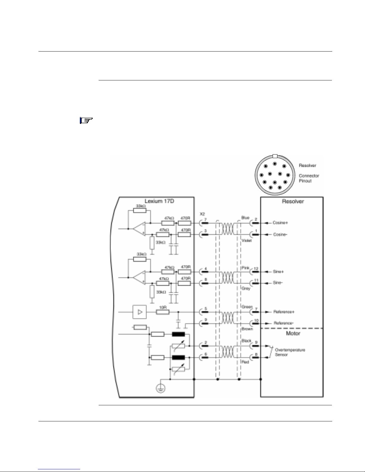
Signal Wiring
Lexium BPH
Resolver
Connection
(excluded
BPH055)
The following diagram shows the connections between the resolver and the 17D
drive.
Note: The standard Lexium BPH series servo motors are equipped with two-pole,
integral resolvers. The thermistor contact in the servo motor is connected via the
resolver cable to the 17D drive.
9
8
1
1210
2
3
4
7
P
11
6
5
60
Continued on next page
Page 75

Signal Wiring, continued
Lexium BPH055
Resolver
Connection
The following diagram shows the encoder input connections between the encoder
and the 17D drive.
Note: The BPH055 servo motors are equipped with two-pole, integral resolvers.
The thermistor contact in the servo m otor is connected via the resol ver ca ble to the
17D drive..
1
8
7
6
5
9
BPH055
2
3
4
Continued on next page
61
Page 76

Signal Wiring, continued
Lexium SER
Resolver
Connection
The following diagram shows the connections between the resolver and the 17D
drive.
Note: The standard Lexium SER series servo motors are equipped with two-pole,
integral resolvers. The thermistor contact in the servo motor is connected via the
resolver cable to the 17D drive.
9
8
1
1210
2
3
4
Green
Yellow
White
9
5
8
7
3
4
7
P
11
6
5
62
Brown
Grey
Pink
Black
Grey/Pink
4
6
7
1
2
8
5
9
2
6
Continued on next page
Page 77

Signal Wiring, continued
Lexium BPH
Encoder
Connection
The following diagram shows the encoder input connections between the encoder
and the 17D drive.
Note: The BPH series servo motors can be optionally fitted with a single-turn or
multi-turn sine-cosine encoder, which is used by the 17D positioning or extremely
smooth running. In addition, the thermistor contact in the servo motor is connected
via the encoder cable to the 17D drive.
Encoder
HIPERFACE
Connector
Pinout
11
1
1210
9
8
1316
17
15
E
7
6
2
3
14
4
5
Continued on next page
63
Page 78

Signal Wiring, continued
Lexium SER
Encoder
Connection
The following diagram shows the encoder input connections between the encoder
and the 17D drive.
Note: The SER series servo motors can be optionally fitted with a single-turn or
multi-turn sine-cosine encoder, which is used by the 17D positioning or extremely
smooth running. In addition, the thermistor contact in the servo motor is connected
via the encoder cable to the 17D drive.
Encoder
White
Brown
Green
Yellow
Grey
Pink
8
4
9
5
6
7
HIPERFACE
Connector
Pinout
9
1
2
3
1210
P
11
4
8
7
6
5
64
Red/Blue
Blue
Black
Grey/Pink
10
11
1
2
Gnd
Continued on next page
Page 79

Signal Wiring, continued
Incremental
Encoder
Emulation
The following diagram shows the incre mental enc oder output c onnection s between
the 17D drive and the motion controller.
Note: The drivers are supplied from an internal supply voltage.
must always be connected to the controller ground.
P
Com
Use a cable with twisted pairs and shield (max. length: 10m.)
Lexium 17D
RS-485
RS-485
=
=
RS-485
5V
X5
5
4
2
3
8
1
6
7
Reserved
P
A+
A-
M+
M-
Com
B+
B-
Motion Controller
RS-485
RS-485
Gnd
RS-485
Chan A
Marker
Chan B
Incremental
Encoder Output
Functional
Description
The position of the servo motor shaft is calculated using the cylic-absolute signals
from the resolver or encoder. The calculated position information is used to
generate two incremental-encoder compatible signals (A and B) with a 90° phase
difference and a marker pulse.
Continued on next page
65
Page 80

Signal Wiring, continued
SSI Encoder
emulation
SSI Encoder
Output
Functional
Description
The following diagram shows the connections between a motion controller and the
17D drive.
Note: The drivers are supplied from an internal supply voltage. P
must always
Com
be connected to the controller ground.
Lexium 17D
RS-485
=
=
=
=
RS-485
5V
X5
6
7
8
Nc
1
4
5
Data +
Data -
Com
P
Clock +
Clock -
Motion Controller
RS-485
Gnd
RS-485
Data
Clock
The SSI interface is synchronous serial absolute-encoder emulation. The position
of the servo motor shaft is calculated using the cyclic-absolute signals from the
resolver or encoder. This calculation is then used to generate a synchronous,
serial, cyclic-absolute 12-bit information output that is compatible with the data
format of normal commercial SSI absolute encoders. A total of 24 bits are
transmitted as follows:
l The upper 12 bits contain the number of turns (multi-turns) or are fixed at zero
(single turn)
l The lower 12 bits contain the cyclic absolute position information.
The signal sequence can be output in either:
l Gray code
l Binary code
The count increments positively when the motor shaft is rotating clockwise (when
viewed from the shaft end).
66
Continued on next page
Page 81

Signal Wiring, continued
Diagram of
master-slave
operation
Incremental
encoder
emulation
The encoder int erfac e ca n be used to link one or more 17 D HP d riv es to gether in a
master-slave operation, as shown in the following diagram. The UniLink software
allows you to setup the parameters for the slave drive(s).
Note: In this configuration, the analog setpoint inputs are disabled, a Analog Com
and I/O Com (connector X3) must be connected together.
Slave
Lexium 17D
RS-485
=
=
=
=
PCom
RS-485
+5 V
X5
5
4
1
6
7
A +
A -
B+
B-
X5
5
4
1
6
7
Master
Lexium 17D
Com
P
RS-485
Chan A
Chan B
RS-485
Note: Up to 16 slaves drives can be controlled by the master drive.
SSI encoder
emulation
Lexium 17D
=
=
Note: Only one slave drive can be controlled by the master drive.
Slave
RS-485
+5 V
PCom
RS-485
Master
P
Com
Lexium 17D
RS-485
Chan A
Chan B
RS-485
X5
6
7
1
5
4
Data +
Data -
CLK+
CLK-
X5
6
7
1
5
4
67
Page 82

Signal Wiring, continued
External
Incremental
encoder
connection
The following diagram shows the incremental encoder input connections between
the 17D drive and an external incremental encoder.
Note: The receivers are supplied from an internal supply voltage.
must always be connected to the encoder ground.
P
Com
Incremental encoder is powered by an external Power Supply.
Lexium 17D
RS-485
RS-485
=
=
RS-485
5Vdc
X5
5
4
2
3
8
1
6
7
Reserved
A+
A-
M+
M-
Com
P
B+
B-
Power
Supply
+ Vdc
Gnd
Incremental encoder
Chan A
Marker
Gnd
Chan B
Vdc
Gnd
RS-485
RS-485
RS-485
68
Page 83

Signal Wiring, continued
External SSI
encoder
connection
The following diagram shows the connections between an external SSI encoder
and the 17D drive.
Note: The drivers are supplied from an internal supply voltage.
must always be connected to the encoder ground.
P
Com
SSI encoder is powered by an external Power Supply
Lexium 17D
RS-485
=
=
=
=
* See Telemecanique XCC range
5Vdc
RS-485
X5
6
7
8
Reserved
1
5
4
Data+
Data -
Com
P
Clock +
Clock -
Power
Supply
+Vdc
Gnd
SSI encoder *
RS-485
Gnd
RS-485
Vdc
Gnd
69
Page 84

Analog I/O Connection
Analog Inputs The following diagram s hows the connect ions bet ween th e two fu lly prog rammable,
differential analog inputs on the 17D drive and a user device. (Refer to the list of
pre-programmed functions contained in the UniLink online help.)
Note: The Analog Com must always be connected to the user device Com as a
ground reference.
Servo Motor
Rotation
The standard setting for direction of positive rotation of the servo motor shaft is
clockwise (looking at the shaft end) and is achieved as follows:
Direction
l Positive voltage on connector X3, between terminals 4 (+) and 5 (-), or
l Positive voltage on connector X3, between terminals 6 (+) and 7 (-)
To reverse the directio n o f ro tation, change the ROT. DIRECTION param ete r in th e
"Speed controller" window; this window is accessed via the UniLink Configuration
software.
70
Continued on next page
Page 85

Analog I/O Connection, continued
Analog Outputs The following diagram shows the connections between the two programmable,
analog outputs on the 17D drive and a typical user device. (Refer to the list of preprogrammed functions in the UniLink online help.)
The outputs (+/-10V wi th 10-bit resol ution) can be configur ed for various monitori ng
functions such as current or actual speed. The default settings are:
l Analog Out 1: Tachometer voltage (speed). The output delivers ±10V at the
preset limit speed.
l Analog Out 2: Current setpoint (torque). The output delivers ± 10V at the
preset peak current (effective RMS value).
Note: Output impedance of the analog outputs (2K2) must be taken into account
when there is a c onnec tion to an us er devi ce: di vider due to the input imped ance of
the user device.
71
Page 86

Fault Relay and Digital I/O Connection
Digital Inputs
and Outputs
The following diag ram shows th e connecti ons betw een the faul t relay, the four fullyprogrammable, digi tal inputs, dedicated enable input and two digital outputs on the
17D drive and typical user devices. (A list of pre-programmed functions is
contained in the UniLink online help.)
100nF
25Ω
25Ω
72
Continued on next page
Page 87

Fault Relay and Digital I/O Connection, continued
Using Functions
Pre-programmed
into the Drive
Fault Relay- The isolated fault relay contacts are closed during normal operation
and open when a fault condition exists. Th e relay sta te is not af fected by the e nable
2
signal, I
t limit or warnings. All faults cause the Fault RA/RB contact to open and
the switch-of f of the output sta ge. A list of error messages can be found in chapter
Troubleshooting.
Digital Inputs 1, 2, 3 and 4 - You can use the four digital inputs to initiate preprogrammed functions that are stored in the drive.
Normally, the Input 3/Input 4 terminal s (X3/13 and X3/14) are programmed for the
connection of limi t-switches. When they are connected as limit-switch positive/
negative (PSTOP/NSTOP), a low PSTOP signal (open) on input terminal X3-13,
inhibits the positive direction of axis rotation and a low NSTOP signal (open) on
input terminal X3-14, inhibits the negative direction of axis rotation. In both cases,
the ramp function remains effective.
WARNING!
LIMIT SWITCH HAZARD
Once they are tripped, the limit switches must remain in that condition (PSTOP/
NSTOP signals low) in order to inhibit the corresponding direction of motion.
Failure to observe this precaution can result in severe injury .
Digital Outputs 1 and 2 - You can use the two digital outputs to send messages
from pre-programmed functions that are stored in the drive.
Enable Input - This is a dedicated, level-sensitive (as opposed to edge-sensitive)
hardware input which will enable the output stage of the drive when 24 Vdc is
applied and no fault conditions exist.
Note: The hardware enable is powered up upon detection of state sens e versus
transition sensitiv ity. Refer to the UniLink on-line help for software enable
information.
73
Page 88

Serial Communications Connection
Serial
Communications
Connection
Diagram
The following diagram depicts the RS-232 communication connection between the
Lexium 17D and a PC.
Pcom
See wiring in Appendix D
The setting of the operating, position control, and motion-block parameters can be
carried out with an ordinary commercial PC.
Connect the PC interface (X6) of the servo amplifier while the supply to the
equipment is switched off via a normal commercial 3-core cable to a serial
interface on the PC. Do not use a null-modem link cable!
74
The interface is electrically isolated through an optocoupler, and is at the same
potential as the CANopen interface.
Page 89

CANopen
Interface
The interface for connection to the CAN bus (default 500 kBaud). The integrated
profile is based o n the commu nication p rofile CANo pen DS301 and the driv e profi le
DSP402.
The following functions are available in connection with the integrated position
controller:
Jogging with variable speed, reference traverse (zeroing), start motion task, start
direct task, digital setpoint provision, data t rans mission functions and many ot hers .
Detailed information can be found in the CANopen manual. The interface is
electr ically isolated by optocouplers, and is at the same potential as the RS232
interface. The analog setpoint inputs can still be used.
If the analog setpoint inputs are not used, then Analog Com and I/O Com
(terminal X3) must be joined together !
=
=
Lexium 17D
CAN
+5
PGND
X3
10
Analog Com
18
I/O Com
X6
9
120Ω*
6
5
* according to line impedance
CAN ref. to ISO 11898
(when analog
setpoints are not
in use)
CANH
CANL
PGND
CAN-Server/Client
120Ω*
CAN
75
Page 90

CAN bus cable To meet ISO 11898 you should use a bus cable with a characteristic impedance of
120 Ω. The maximum usable cable length for reliable communication decreases
with increasing transmission speed. As a guide, you can use the following values
which we have measured, but they are not to be taken as assured limits:
Cable data: Characteristic impedance 100-120Ω
Cable capacitanc e max. 60 nF/km
Lead resistance (loop) 159.8 Ω/km
Cable length, depending on the transmission rate
Transmission rate (kBauds) max. cable lenght (m)
1000 20
500 70
250 115
Lower cable capacitance (max. 30 nF/km) and lower lead resistance (loop,
115 Ω/km) make it possible to achieve greater distances.
(Characteristic impedance 150 ± 5Ω =:> terminating resistor 150 ± 5Ω).
For EMC reasons, the SubD connector housing must ful fill the following conditions:
l metal or metallized housing
l shield connection to housing.
X6 X6 X6 X6
1
6
*
9
5
CANL
CANH
PGND
Shield
1
6
9
5
* about 120Ω according to line impedance
1
6
9
5
CANL
CANH
PGND
Shield
1
6
*
9
5
76
Page 91

Stepper Motor Control Interface Connection
Stepper-Motor
Control Interface
Connection
Functional
Description
Stepper-Motor
Control Interface
Connection
Diagram
This interface can be us ed to co nnect th e servo drive to a third- party s tepper m otor
controller. The parameters for the drive are set using the UniLink software and the
number of steps are adjustable to allow the drive to correlate to the step-direction
signals of any stepper-motor controller. In this configuration, the analog inputs are
disabled and the drive can provide various monitoring signals.
The following diagram depicts the communication connection between the Lexium
17D and a stepper-motor controller.
Continued on next page
77
Page 92
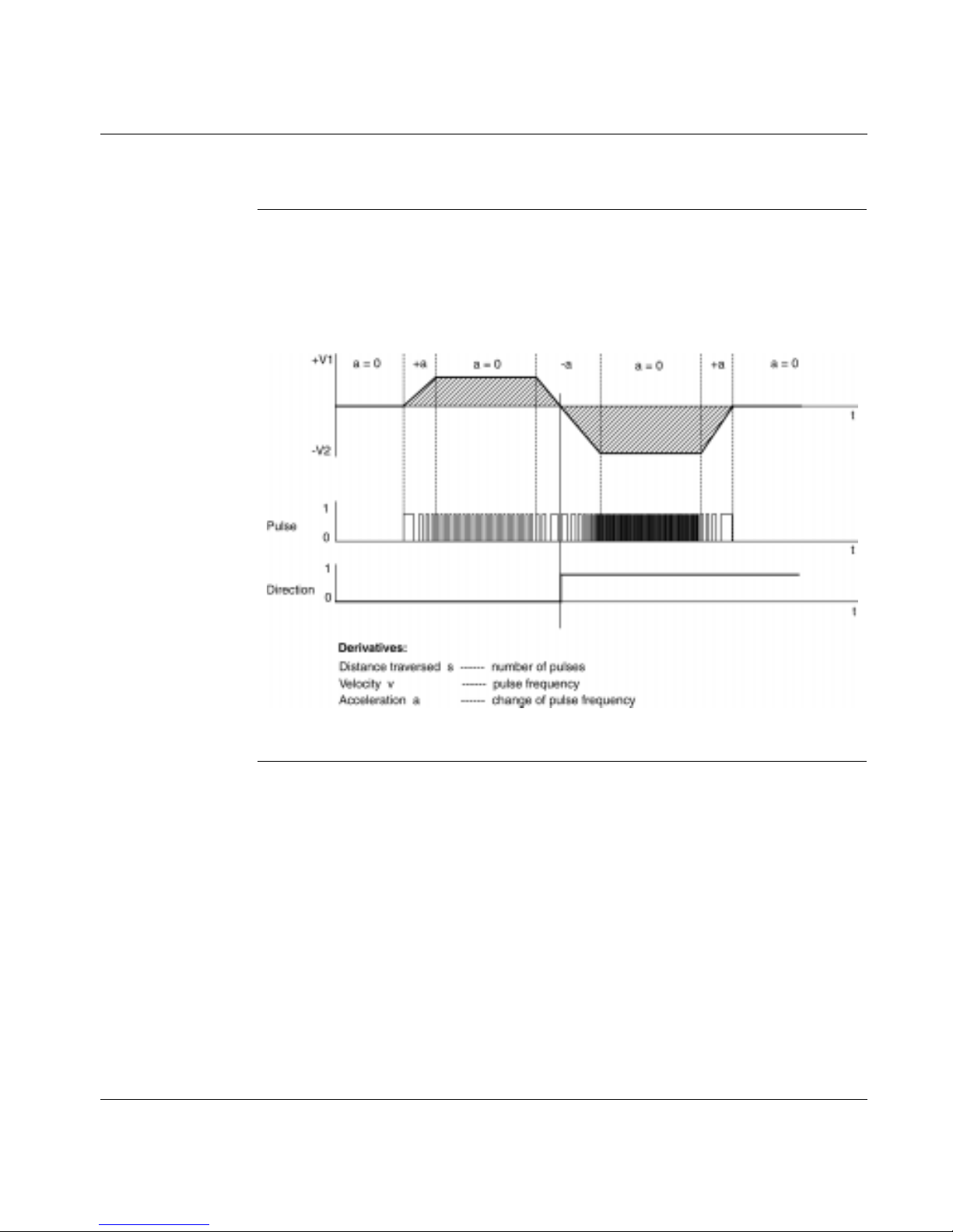
Stepper Motor Control Interface Connection , continued
Stepper-Motor
Speed Profile
and Signal
Diagram
The following is the speed profile and signal diagram of the stepper-motor
configuration.
78
Page 93

At a Glance
System Operation
5
What’s in this
Chapter
This chapter provid es inform ation on operatin g the Lexiu m 17D serie s servo dri ves
and includes the following topics:
Topic Page
Powering up and powering down the system 80
Description of the restart lock -AS- 84
Procedure for verifying system operation 92
Front panel controls and indicators 96
890 USE 120 00 79
Page 94

Chapter 5 System Operation
Powering Up and Powering Down the System
Power-on and
Power-off
Characteristics
The following diagram illustrates the functional sequence that occurs when the
drive is turned on and off.
Continued on next page
80
890 USE 120 00
Page 95

Chapter 5 System Operation
Powering Up and Powering Down the System, continued
Stop Function If a fault occurs the output stage of the servo a mplifier is switched off and the
Fault RA/RB contac t is opened . In addition, a g lobal error s ignal can be g iven out at
one of the digital outputs (terminals X3/16 and X3/17). These signals can be used
by the higher-level control to finish the current PLC cycle or to shut down the drive
(with additional brake or simila r.).
For MHDAppppA00 only: The built-in restart lock -AS- can be used to switch off the
drive via a positive action safety relay, so that personnel safety is ensured at the
drive shaft.
Instruments which are equipped with a selected "Brake" function use a special
sequence for switching off the output stage.
The Stop functions are defined in EN 60204 (VDE 0113), Para. 9.2.2, 9.2.5.3.
There are three cat egories of Stop functions:
l Category 0 : Shut down by immedia tely sw itching of f the s upply of en ergy to the
drive machinery (i.e an uncontrolled shut-down);
l Category 1: A controlled shut-down, during which the supply of energy to the
drive machine ry is maint ain ed to perform th e shut-down, and where th e energy
supply is only interrupted when the shut-down has been completed;
l Category 2: A controlled shut-down, where the supply of energy to the drive
machinery is maintained.
Every machine must b e equipp ed with a S top function to Ca tegory 0. S top fun ctions
to Categories I a nd/or 2 must be provided if the sa fety or functi onal r equirem ent s of
the machine make this necessary.
890 USE 120 00 81
Page 96

Chapter 5 System Operation
Powering Up and Powering Down the System, continued
Emergency Stop
strategies
The Emergency Stop function is defined in EN 60204 (VDE 0113), Para. 9.2.5.4.
Implementation of the Emergency Stop function:
l Category 0:
The controller is switched to "disable", the electrical supply (400VAC) is
disconnected.
The motor must be held by an electromagnetic holding device (brake).
In single axis or multiaxi s syste ms with co nnected DC-link b us (int ermediate circuit)
the motor leads have to be disconnected by a changeover switch and shortcircuited by resistors connected in a star configuration.
l Category 1:
If hazardous conditions can result fr om an emergency stop switch-off with an
unbraked run-down, then the drive can be switched off by a controlled shut-down.
Stop Category 1 permits electromotive braking with a switch -off when zero speed
has been reached. Safe shut-down can be achieved, when the loss of the mains
supply is not rated as a fault and the control takes over the disabling of the servo
amplifier.
In the normal situation, only the supply power is switched off in a safe manner.
The 24V auxiliary supply remains switched on.
82
Continued on next page
890 USE 120 00
Page 97

Powering Up and Powering Down the System, continued
Wiring example Stop and Emergency Stop function (Category 0)
L1
L2
L3
PE
K10
Chapter 5 System Operation
XOA
3 2 1
LEXIUM 17
24 Vdc Com
24 Vdc
Enable
X3
15 2 3
K10
K11
Fault RA/RB
F
Emergency-Off
OFFON
K10 K10
X9
1
2
3
4
5
6
+24Vdc
B RB
R
K30
Brake-
Brake+
Gnd
(Green)
W2
V2
U2
K20
Servo
Motor
+24Vdc Com
890 USE 120 00 83
K30 K11K11
K20K10K30
K11 is normally closed
(no fault of equipemen t)
Page 98

Chapter 5 System Operation
Description of the restart lock -AS- (MHDA••••A00 drives only)
Advantages of
the restart lock
A frequently required application task is the protection of personnel against the
restarting of drives. This can not be achieved by an electronic inhibit, but must be
implemented with mechanical elements (positively driven relay contacts).
To get round this problem, up to now either the main contactor in the mains supply
line was switched off, or another contactor was used to disconnect the motor from
the servo amplifier.
The disadvantages of this method are :
l the DC-link has to be charged up again at restart
l wear on the contacts of the contactors, caused by switching under load
l extensive wiring required, with additional switching components
The restart lock -AS- avoids these disadvantages. A safety relay in the servo
amplifier is activated either by the PLC or manually. Positively driven contacts
provide a safe disconnection of the amplifier, the setpoint input of the servo
amplifier is inhibited, and a signal is sent to the safety circuit.
Advantages of the restart lock -AS- :
l the DC-link remains charged up, as long as the mains supply line remains
active
l only low voltages are switched, so there is no contact wear
l very little w iring is required
l the functionality and the personnel safety when using the circuit
recommendations in this documentation have been approved by the trade
liability association.
84
Continued on next page
890 USE 120 00
Page 99

Description of the restart lock -AS-
Chapter 5 System Operation
Functional
description
The connector (X10) is mounted on the front panel of the Lexium 17 D. The coil
connections and a make (n.o.) contact of a safety relay are available through 4
terminals on this connector.
Two contacts switch off the driver supply of the output stage in the servo amplifier,
and short the internal setpoint signal to Analog Com (0 V).
The make (n.o.) contact used for monitoring is looped into the control circuit.
If the safety relay is not energized, then the monitoring contact is open and the
servo amplifier is ready for operation.
If the drive is elec tronically braked, the servo amplifier is disabled and the motor-
holding brake is on , th en the safety relay is energized (ma nu ally or by the controls).
The supply voltage for the driver circuit of the output stage is switched off in a safe
manner, the internal setpoint is shorted to 0V, and the monitoring contact bridges
the safety logic in the control circuit of the system (monitoring of protective doors
etc.)
Even if the output stage or driver is destroyed, it is impossible to start the motor.
If the safety relay itself is faulty, then the monitoring contact cannot bridge the
safety logic of the system. Opening the protective devices will then switch off the
system.
890 USE 120 00 85
Page 100

Chapter 5 System Operation
Description of the restart lock -AS-, continued
Block diagram
charging
circuit
Mains
24Vdc
KSI+
KSI-
KSO1
KSO2
3~
DC/DC converter
2
X10
4
3
1
2
monostable
AS
relay
0V
setpoint
Note: AS relay :
Its main features are:
- according to EN 50205, IEC 255, IEC 664
- monostable
- high mechanical service life
- high switching reliability
- approvals TUV, UL and CSA.
223
DC link
control logic
3
M
3~
6
activation
6
6
86
Continued on next page
890 USE 120 00
 Loading...