

Lexington Forge SSW30FTAL, SSW30STAL, SSW30FTPB, SSW30FTAPB, SSW30STAPB Owner's Manual
SAFETY NOTICE: Read this entire manual before you install and use your appliance. If not properly
installed, a house fi re may result. To reduce the risk of fi re, follow the installation instructions. Failure to
follow instructions may result in property damage, bodily injury, or even death. Contact local building, fi re
offi cials or authorities having jurisdiction about permits, restrictions and installation inspection require-
ments in your area.
These units are mobile home approved for U.S. and Canada
EPA APPROVED HIGH EFFICIENCY
AIR TIGHT WOOD STOVE
FOR RESIDENTIAL INSTALLATION
We recommend that our products be installed and serviced
by professionals who are certifi ed in the U.S. By NFI
(National Fireplace Institute) or in Canada by WETT
(Wood Energy Technical Training).
6" (152mm) Flue Required
OWNERS MANUAL
MODELS:
SSW30FTAL, SSW30STAL, SSW30FTPB
SSW30FTAPB, SSW30STAPB

2 63D0001
CONTENTS
Specifi cations ................................................................... 03
Questions? ......................................................................... 04
Pre-installation instructions .............................................. 05
Unpacking and leg installation .......................................... 07
Stove set-up ....................................................................... 09
Clearances ......................................................................... 11
Installation ......................................................................... 12
Proposition 65 Warning:
Fuels used in gas, woodburning or oil fi red appliances, and the
products of combustion of such fuels, contain chemicals
known to the State of California to cause cancer, birth
defects and other reproductive harm.
California Health and Safety Code Sec. 25249.6
WARNING
ACCESSORIES
1. Variable Speed Blower—Part no.: BLOTWS
2. Outside Air Termination Kit—Part no.: SSWOATK
3. Mobile Home Installation Kit—Part no.: SSWMHIK
4. Gold Legs—Part no.: SSW30CLGD
5. Gold Door Trim—Part no.: SSW30GDTK
6. Nickel Legs—Part no.: SSW30CLN
7. Nickel Door Trim—Part no.: SSW30NDTK
8. Gasket Kit—Part no.: SSW30GK
9. Glass Door Kit—Part no.: SSW30GDK
10. Glass Door Handle Kit—Part no.: SSW30GDHK
11. Ash Pan Door Handle Kit—Part no.: SSW30AHK
12. Pedestal Ash Pan Door Handle Kit—Part no.:
SSW30APHK
13. Secondary Air Tubes Kit—Part no.: SSW30SAT
14. Baffl e Insulation Kit—Part no.: SSW30BI
15. Brick Kit—Part no.: SSW30BK
16. Primary Air Module Kit—Part no.: SSW30PAM
Operation ........................................................................... 14
Maintenance ...................................................................... 17
Replacement parts ............................................................. 20
Illustrated Parts Breakdown .............................................. 22
FAQs ................................................................................. 24
Warranty ............................................................. Back Cover
IMPORTANT
Read these instructions carefully before installing or trying to operating this woodburning appliance.
INSTALLER
Please leave these instructions with the appliance.
OWNER
Please retain these instructions for future reference
.
63D0001 3
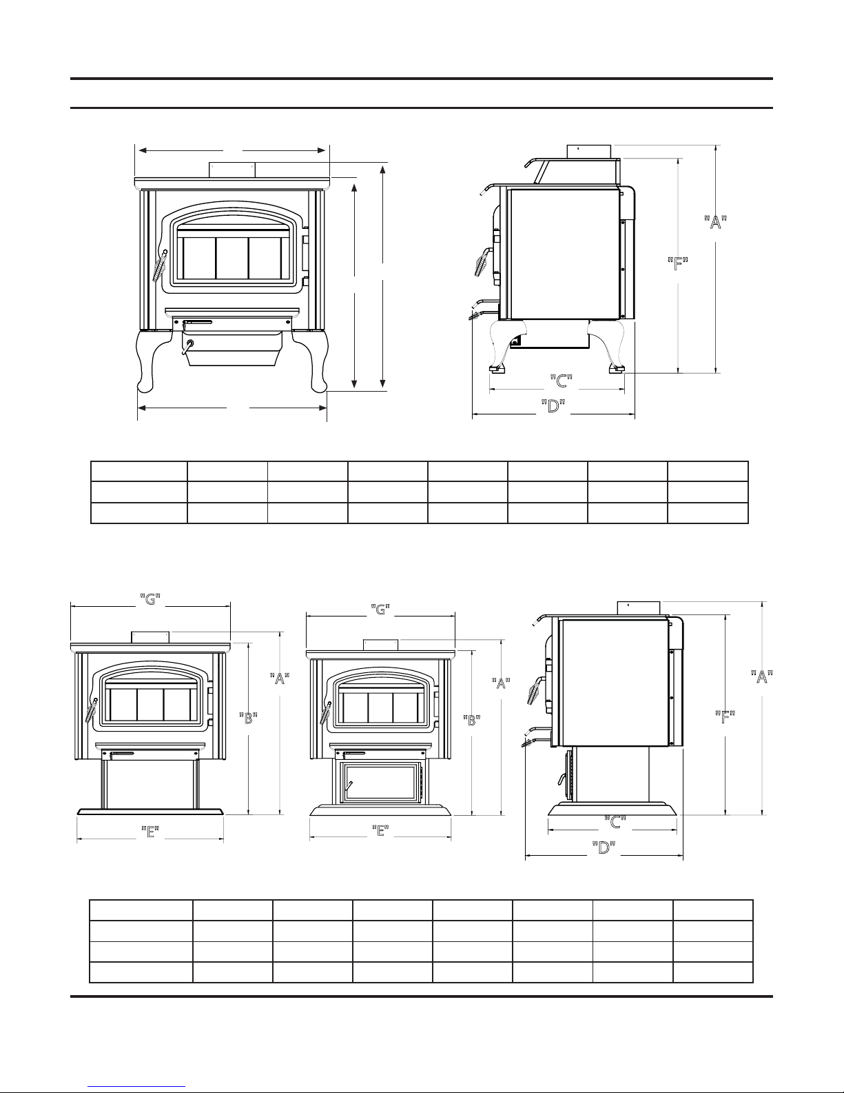
SPECIFICATIONS
MODEL A B C D E F G
SSW30FTAL 30¼ 28¼ 19¼ 24¼ 26 NA 27¾
SSW30STAL 33¾ 28¼ 19¼ 24¼ 26 32 27¾
MODEL A B C D E F G
SSW30FTPB 32¾ 30¾ 18½ 24¼ 25½ NA 27¾
SSW30FTAPB 32¾ 30¾ 19¾ 24¼ 26⅜ NA 27¾
SSW30STAPB 36¼ 30¾ 19¾ 24¼ 26⅜ 34½ 27¾
"D"
"C"
"F"
"A"
"G"
"B"
"A"
"E"
"D"
"C"
"F"
"A"
SSW30FTAL
SSW30STAL
SSW30FTAPB
SSW30STAPBSSW30FTPB
"G"
"B"
"A"
"E"
OVERALL DIMENSIONS
"A"
"B"
"E"
"G"

4 63D0001
QUESTIONS?
Log Length 20"
Maximum burn time2 10 hours
Average area heated (sq.ft)
2
2,200 sq. ft.
Range of heat output3 11,000-30,600
Maximum heat output1 55,400
EPA emissions rating (g/h, non-catalytic) 2.5 gph
Weight 520 lbs
Loading Front
Air Control Manual
1. Maximum burn times and heat outputs are based on laboratory testing using full loads of seasoned hardwoods, and may vary in
individual use depending on how the stove is operated, type and moisture content of fuel, and other factors. Maximum burn times
are achieved under different operating conditions than are maximum heat outputs.
2. These values are based on operation in building code-conforming homes under typical winter climate conditions in the U.S. If your
home is of nonstandard construction (e.g. unusually well-insulated, not insulated, built underground, or if you live in a more severe
and more temperate climate), these fi gures may not apply. Since so many variables affect performance, consult your Lexington
Forge Authorized Dealer to determine realistic expectations for your home.
3. Under specifi c conditions used during EPA emissions testing.
NEED TO ASK QUESTIONS? REQUIRE PARTS INFORMATION?
First, contact the Lexington Forge Dealer from whom you purchased your stove, for parts and service. Have the following information
ready:
• Date of purchase
• Serial number (from the back of your stove)
• Model number (from the back of your stove)
• Dealer name and phone
If you still need assistance, contact Lexington Forge technical support (below).
WONDERING ABOUT THE WARRANTY?
See the last page of this manual for general warranty information. For additional information, contact your Lexington Forge dealer or
Lexington Forge Parts and warranty.
Lexington Forge
Technical Service, Parts & Warranty
Phone: 877-406-9180
Fax: 877-406-5647
Model and product serial numbers can be found on the certifi cation label of your stove.

63D0001 5
PRE-INSTALLATION INSTRUCTIONS
BEFORE INSTALLATION OF YOUR APPLIANCE
1. Check with the building inspector’s offi ce for compliance with local codes; a permit may be required.
2. This appliance requires a masonry or prefabricated chimney listed to ULC S629 (Canada) and UL 103HT (U.S.) sized correctly.
3. A 6" (152mm) diameter fl ue is required for proper performance.
4. Always connect this unit to a chimney and NEVER VENT TO ANOTHER ROOM OR INSIDE A BUILDING.
5. DO NOT connect this unit to any duct work to which another appliance is connected such as a furnace.
6. DO NOT connect this unit to a chimney fl ue serving another appliance.
7. The connector pipe and chimney should be inspected periodically and cleaned if nescessary.
8. Remember the clearance distances when you place furniture or other objects within the area. DO NOT store wood, fl ammable
liquids or other combustible materials too close to the unit. Refer to certifi cation label on back of your unit for required
clearances.
9. Contact your local municipal or provincial fi re authority for information on how to handle a chimney fi re. Have a clearly
understood plan to handle a chimney fi re. In the event of a chimney fi re, turn air control to closed position and CALL THE
FIRE DEPARTMENT.
10. DO NOT tamper with combustion air control beyond normal adjustment.
11. If installing in a mobile home, use mobile home kit.
WHY THE CORRECT FLUE SIZE IS IMPORTANT — 6" (152 MM)
Draft is the force, which moves air from the appliance up through the chimney. The amount of draft in your chimney depends on the
length of the chimney, local geography, nearby obstructions, and other factors. Too much draft may cause excessive temperatures in
the appliance. An uncontrolled burn, a glowing red part or chimney connector indicates excessive draft. Inadequate draft may cause
back puffi ng into the room and “plugging” of the chimney and/or cause the appliance to leak smoke into the room through appliance
and chimney connector joints.
Today’s solid fuel appliances are much more effi cient than in the past. The units are designed to give you controlled combustion, as
well as maximum heat transfer, using less fuel to do so. The design of your new appliance is such that the exhaust “smoke” is now at
lower temperatures than in the past, therefore requiring proper chimney size to give adequate draft. If your chimney is too large, the
heating appliance will have a diffi cult time to raise the “chimney fl ue” temperature to give adequate draft, therefore causing a smoke
back up, poor burn, or both.
Should you experience such a problem call in a local chimney expert.
With the door closed, the rate of burning is regulated by the amount of air allowed to enter the unit through the air control. With
experience you will be able to set the control for heat and burning time desired.
Once the required chimney draft is obtained, operate only with doors closed and open slowly when re-fueling. (This will reduce or
eliminate smoke from entering the room.)
After reading these instructions, if you have any doubt about your ability to complete your installation in
a professional like manner, you should obtain the services of an installer versed in all aspects as to the
correct and safe installation. DO NOT use temporary, makeshift compromises during installation.
CAUTION

6 63D0001
CAUTION
Attempts to achieve higher output rates that exceed heater design specifi cations can result in permanent damage to the heater. The
recommended wood load is level with the top of the fi rebricks. Overloading may prevent suffi cient air entering the heater to properly
fuel the fi re.
Important: For optimum heater performance at “low” burn rate, operate the fan at low speed.
An outside air kit is available from your Lexington Forge dealer.
Optional Blower: 70v 130 CFM Model: BLOTWS
• OPERATE THIS HEATER ONLY WITH THE DOOR CLOSED.
• DO NOT BURN GARBAGE OR FLAMMABLE FLUIDS.
• DO NOT USE CHEMICALS OR FLUIDS TO START THE FIRE.
CAUTION
THIS HEATER IS EXTREMELY HOT WHILE IN OPERATION.
SERIOUS BURNS CAN RESULT FROM CONTACT.
KEEP CHILDREN, PETS, CLOTHING AND FURNITURE AWAY
DANGER
RISK OF ELECTRIC SHOCK.
DISCONNECT POWER BEFORE
SERVICING UNIT.
63D0001 7
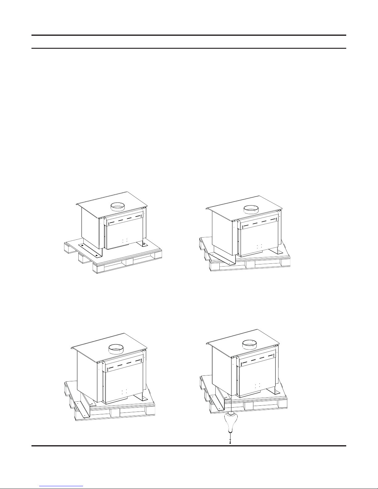
REMOVING THE STOVE FROM THE PALLET AND ATTACHING THE LEGS ON THE SSW30(F/S)TAL
Caution: Stove is extremely heavy. You will need help installing the legs and moving your stove to its fi nal
location.
Please note: The fi berboard baffl e is secured with two screws for shipping purposes only. These screws are
located behind the rear tube and may be removed prior to use, if so desired.
The legs are packed inside the stove with bolts for assembling legs to the stove. Useful note: If you misplace the bolts in the leg pack,
the bolts used to hold the shipping bracket to the stove can be used to hold the legs in place.
Tools required: 7/16" & 9/16" wrench or socket.
1) Remove the foam leg pack from inside your stove. The pack should contain 4 legs and 8 bolts.
2) To begin the leg installation remove the bolts from the hold down brackets from the pallet only. This is so you will be able to
move the stove to the edge of the pallet and install the legs one at a time. (9/16" wrench or socket.) Figure 1
3) Slide the stove so that a rear corner of the stove is extended past the edge of the pallet just enough to install rear leg. Figure
2
4) Remove both bolts from the rear leg location of the hold down bracket and one of the bolts from the front leg location of the
same hold down bracket. (7/16" wrench or socket.)
5) Swing hold down bracket out from stove just far enough to install rear leg. Figure 3
6) Use the bolts provided to install the rear leg. (7/16" wrench or socket.) . Figure 4
UNP ACKING AND ATTACHING LEGS
Figure 2
Figure 1
Figure 3
Figure 4
8 63D0001
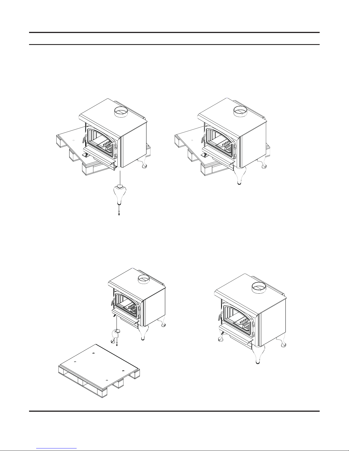
UNP ACKING AND ATTACHING LEGS
7) With rear leg installed, pivot the stove so that the hold down bracket is off the pallet. The stove should be resting the installed
leg on the fl oor, one support bracket on the pallet and the partially loosened support bracket hanging free. Have someone
steady the stove to avoid tipping.
8) Remove the remaining bolt from the hold down bracket and install front leg. Figures 5 & 6
9) Pivot the stove or twist the pallet so the rear corner of the remaining support bracket is extended over the pallet just far
enough to install the rear leg.
10) Remove both of the bolts from the top rear section of the hold down bracket and one of the bolts from the top front section of
the hold down bracket.
11) Pivot the hold down bracket out of the way just far enough to install the other rear leg.
12) Pivot the stove or slide the pallet so that the three installed legs are on the fl oor and the stove is completely off the pallet.
13) Remove the fi nal remaining bolt from the hold down bracket and install the fi nal leg.
Figure 5
Figure 6
Figure 7
Figure 8
 Loading...