

Lexington Forge SSI30 Owner's Manual
SAVANNAH WOOD INSERT
FOR RESIDENTIAL INSTALLATION
6" (152mm) Flue Required
MODEL:
SSI30
OWNERS MANUAL
We recommend that our products be installed and serviced
by professionals who are certifi ed in the U.S. By NFI
(National Fireplace Institute) or in Canada by WETT
(Wood Energy Technical Training).
SAFETY NOTICE: Read this entire manual before you install and use your appliance. If not properly
installed, a house fi re may result. To reduce the risk of fi re, follow the installation instructions. Failure to
follow instructions may result in property damage, bodily injury , or even death. Contact local building, fi re
offi cials or authorities having jurisdiction about permits, restrictions and installation inspection requirements
in your area.

CONTENTS
Specifi cations ................................................................... 03
Questions? .........................................................................04
Pre-installation instructions ..............................................05
Unpacking and installation ..............................................07
Removing the fl ue collar ...................................................08
Fan wiring conversion ....................................................... 09
Blower and ash lip assembly ............................................. 10
Clearances to combustibles ............................................... 11
Calculating alternate fl ooring materials ............................12
ACCESSORIES
1. Gold Door Trim—Part no.: SSW30GDTK
2. Nickel Door Trim—Part no.: SSW30NDTK
3. Adjustable Raised Hearth Kit—Part no.: SSI30AH
4. Offset Flue Kit—Part no.: OFC3 & OFC6
Chimney clearances ..........................................................13
Insert and pipe instructions ...............................................14
Installing insert .................................................................. 15
Operation ...........................................................................16
Maintenance ......................................................................18
Replacement parts .............................................................21
Illustrated parts breakdown ...............................................22
F AQs .................................................................................23
Warranty ............................................................. Back Cover
Proposition 65 Warning:
Fuels used in gas, woodburning or oil fi red appliances, and the
products of combustion of such fuels, contain chemicals
known to the State of California to cause cancer, birth
defects and other reproductive harm.
WARNING
California Health and Safety Code Sec. 25249.6
THIS HEATER IS EXTREMELY HOT WHILE IN OPERATION.
SERIOUS BURNS CAN RESULT FROM CONTACT.
KEEP CHILDREN, PETS, CLOTHING AND FURNITURE AWAY
CAUTION
• OPERATE THIS HEATER ONLY WITH THE DOOR CLOSED.
• DO NOT BURN GARBAGE OR FLAMMABLE FLUIDS.
• DO NOT USE CHEMICALS OR FLUIDS TO START THE FIRE.
RISK OF ELECTRIC SHOCK.
DISCONNECT POWER BEFORE
DANGER
INSTALLER
Please leave these instructions with the appliance.
SERVICING UNIT.
OWNER
Please retain these instructions for future reference.
Read these instructions carefully before installing or trying to operating this woodburning appliance.
2 63D4004
IMPORTANT
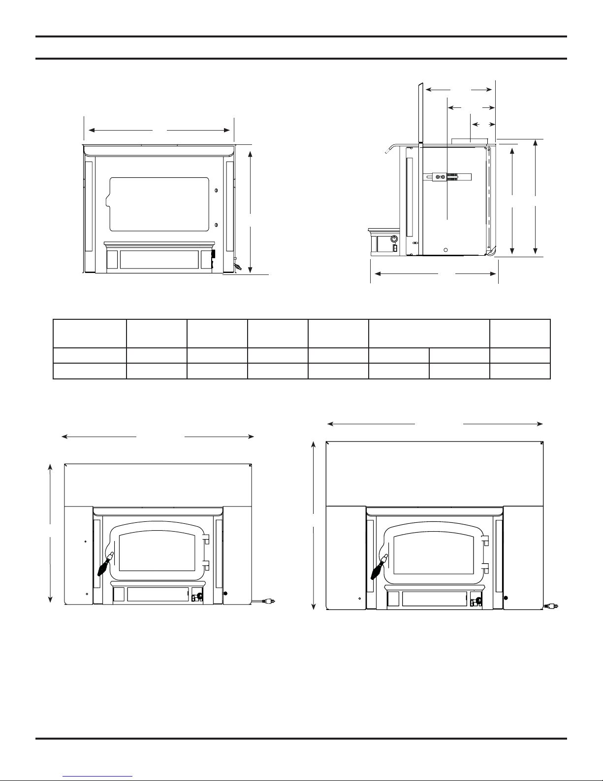
OVERALL DIMENSIONS
"B"
"A"
SPECIFICATIONS
"E"
"F"
"G"
"D"
"A"
"C"
FRONT VIEW
SIDE VIEW
SURROUND
ADJUSTMENT
MODEL A B C D E F G
SSI30 20.50 27.50 22.75 22 14 10 5.50
44"
40"
34"
30"
A. 30" x 40" B. 34" x 44"
63D4004 3
SURROUND OPTIONS

QUESTIONS?
Log Length 20"
Maximum burn time1 10 hours
Average area heated (sq.ft)1 2,200 sq. ft.
Range of heat output2 11,000-30,600
Maximum heat output1 55,400
EPA emissions rating (g/h, non-catalytic)2 3.5 gph
Weight 360 lbs
Loading Front
Air Control Manual
1. Maximum burn times and heat outputs are based on laboratory testing and may vary in individual use depending on how
the insert is operated, type and moisture content of fuel, and other factors. Maximum burn times are achieved under
different operating conditions than are maximum heat outputs. These values are based on operation in building codeconforming homes under typical winter climate conditions in the U.S. If your home is of nonstandard construction (e.g.
unusually well-insulated, not insulated, built underground, or if you live in a more severe and more temperate climate),
these fi gures may not apply. Since so many variables affect performance, consult your Lexington Forge Authorized
Dealer to determine realistic expectations for your home.
2. Under specifi c conditions used during EPA emissions testing.
NEED TO ASK QUESTIONS? REQUIRE PARTS INFORMATION?
First, contact the Lexington Forge Dealer from whom you purchased your insert, for parts and service. Have the following
information ready:
Model and product serial numbers can be found on the certifi cation label of your insert.
• Date of purchase:
• Serial number (from the back of your insert):
• Model number (from the back of your insert):
• Dealer name and phone:
If you still need assistance, contact Lexington Forge technical support (below).
WONDERING ABOUT THE WARRANTY?
See the last page of this manual for general warranty information. For additional information, contact your Lexington
Forge dealer or Lexington Forge Parts and warranty.
Lexington Forge
Technical Service, Parts & Warranty
Phone: 877-406-9180
Fax: 877-406-5647
4 63D4004

PRE-INSTALLATION INSTRUCTIONS
After reading these instructions, if you have any doubt about your ability to complete your installation in
a professional like manner, you should obtain the services of an installer versed in all aspects as to the
correct and safe installation. DO NOT use temporary, makeshift compromises during installation.
CAUTION
BEFORE INSTALLATION OF YOUR APPLIANCE
(NOTE: Before installing your appliance be sure to write down the model and serial numbers and keep them in
a safe place. Once installed this information is no longer visible on your appliance.)
1. Check with the building inspector’s offi ce for compliance with local codes; a permit may be required.
2. This appliance requires a masonry or prefabricated chimney listed to ULC S629 (Canada) and UL 103HT (U.S.) sized
correctly.
3. A 6" (152mm) diameter fl ue is required for proper performance.
4. Always connect this unit to a chimney and NEVER VENT TO ANOTHER ROOM OR INSIDE A BUILDING.
5. DO NOT connect this unit to any duct work to which another appliance is connected such as a furnace.
6. DO NOT connect this unit to a chimney fl ue serving another appliance.
7. The connector pipe and chimney should be inspected periodically and cleaned if nescessary.
8. Remember the clearance distances when you place furniture or other objects within the area. DO NOT store wood,
fl ammable liquids or other combustible materials too close to the unit. Refer to certifi cation label on back of your
unit for required clearances.
9. Contact your local municipal or provincial fi re authority for information on how to handle a chimney fi re. Have a
clearly understood plan to handle a chimney fi re. In the event of a chimney fi re, slide air control to the lowest position
and CALL THE FIRE DEPARTMENT.
10. DO NOT tamper with combustion air control beyond normal adjustment.
WHY THE CORRECT FLUE SIZE IS IMPORTANT — 6" (152 MM)
Draft is the force, which moves air from the appliance up through the chimney. The amount of draft in your chimney
depends on the length of the chimney, local geography, nearby obstructions, and other factors. Too much draft may
cause excessive temperatures in the appliance. An uncontrolled burn, a glowing red part or chimney connector indicates
excessive draft. Inadequate draft may cause back puffi ng into the room and “plugging” of the chimney and/or cause the
appliance to leak smoke into the room through appliance and chimney connector joints.
Today’s solid fuel appliances are much more effi cient than in the past. The units are designed to give you controlled
combustion, as well as maximum heat transfer, using less fuel to do so. The design of your new appliance is such that the
exhaust “smoke” is now at lower temperatures than in the past, therefore requiring proper chimney size to give adequate
draft. If your chimney is too large, the heating appliance will have a diffi cult time to raise the “chimney fl ue” temperature
to give adequate draft, therefore causing a smoke back up, poor burn, or both.
Should you experience such a problem call a local chimney expert.
With the door closed, the rate of burning is regulated by the amount of air allowed to enter the unit through the air control.
With experience you will be able to set the control for heat and burning time desired.
Once the required chimney draft is obtained, operate only with doors closed and open slowly when re-fueling. (This will
reduce or eliminate smoke from entering the room.)
Attempts to achieve higher output rates that exceed heater design specifi cations can result in permanent damage to the
heater. The recommended wood load is level with the top of the fi rebricks. Overloading may prevent suffi cient air
entering the heater to properly fuel the fi re. Important: For optimum heater performance at “low” burn rate, operate the
fan at low speed.
63D4004 5

PRE-INSTALLATION INSTRUCTIONS
PLANNING YOUR INSTALLATION
1. Check with local building offi cial for local code requirements
2. Have your chimney and fi replace cleaned and inspected for serviceability before installing appliance. A professional
chimney sweep can provide this service. They can also offer advice or install chimney liners and your insert.
a. Masonary fi replaces and chimney must be inspected for cracks, loose bricks or mortar. The chimney and fi replace
must be cleaned before installing insert. Dirty chimneys can affect performance and cause fi res.
b. Factory built fi replaces should be inspected for cracks, leaky joints, corrosion, warping, and any sign of structural
or mechanical weakness. Correct any faults before installing insert. Check clearances of chimney to combustible
surface as you inspect joints.
3. Plan your chimney connection system that makes the most sense for your particular situation. Make a list of the component you will need. There are two basic categories of fi replaces—manufactured and masonary. Chimneys can be steel
or masonary. Liners are available to size the chimney to the insert and provide best performance and safety.
The actual connection from the unit to the chimney is made with adapters. One end will fi t the 6” round fl ue collar and
the other end will fi t the chimney liner. Offset adapters are used in low clearance cases where the fl ue of the fi replace
is recessed quite a bit, or the back of the fi replace is tapered to a smaller dimension than the insert.
Use the dimensions guide on page 3 to help you understand if you will need an offset adapter.
4. Here are a few chimneys and connection types to give you an overview:
NOTE: Flue size is important! The cross sectional area of the chimney should not be larger than 3 times the cross sec-
tional area of the insert.
a. Masonary chimney with sealed throat and partial liner extended above the fi replace damper—This is not a reco-
mended system. It requires the insert be removed to clean the chimney . The mass and overall size of many masonary
chimneys can cause start up problems and creosote that can lead to chimney fi res. Be sure to check the size of the
fl ue.
b. Fully lined masonary chimney—This uses a fl exible or ridge liner that is directly connected to the insert using a
fl exible, rigid or offset adapter. A good installation provides good performance and allows you to clean the chimney
without removing the insert, in many cases.
c. Factory built chimney with full liner—Directly connected to the insert using fl exible, rigid or offset adapters.
5. Review mantel, hearth and clearance to combustibles information on page 11. Add to your list any protective shielding,
hearth or surround components you will need to complete the installation.
6. Order all the installation components from your dealer. Once you have them, you are ready to begin.
6 63D4004
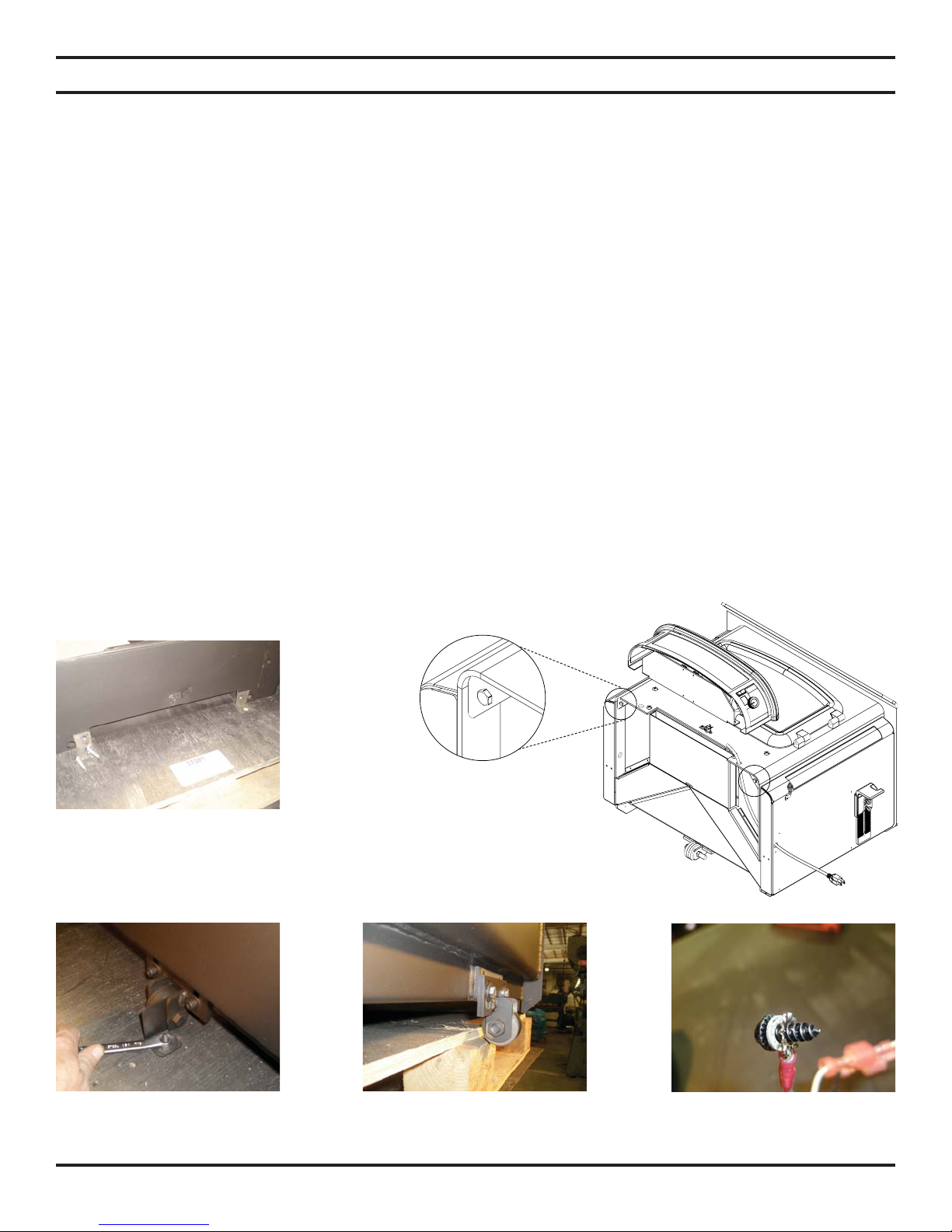
UNPACKING AND INSTALLATION INSTRUCTIONS
UNPACKING AND INSTALLATION INSTRUCTIONS
NOTE: The insert is extremely heavy. Do not attempt to move it without assistance.
Please read all instructions carefully before beginning.
To remove the insert from the pallet you will need a 7/16" wrench or socket.
•
If you are placing the insert on a raised hearth you might consider moving the complete unit close to the raised hearth
•
to save some lifting later.
Remove the two brackets on the front of the insert by removing the four bolts (save the two bolts removed from the front
•
of the stove) shown in Figure 1.
The rear bracket is slipped over the wheel axel and held in place with onebolt shown in Figure 3.
•
If your hearth is not level there are three leveling points on the insert. One on each of the front corners which are easily
•
accessed by sliding the corner of the insert just off the edge of the pallet. Figure 2
If the rear of the insert needs to be adjusted you can slide the rear wheel off the pallet and loosen the two bolts (1/2"
•
wrench) as shown in Figure 4.
The SSI30 is shipped with the power cord for the blower on the right side. If you want to move it to the left side now is
•
the best time as you can access it under the insert easily by sliding the insert just off the edge of the pallet. See page 9
for instructions on converting fan wire from left to right. Make sure you secure the ground wire (green wire) to the side
of the insert using the star washer showin in Figure 5.
Do not attach the blower until the unit is installed in the fi replace.
Figure 1
Figure 2—Leveling points
Figure 3 Figure 4
63D4004 7
Figure 5
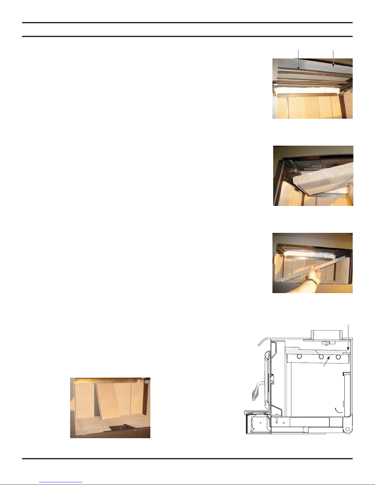
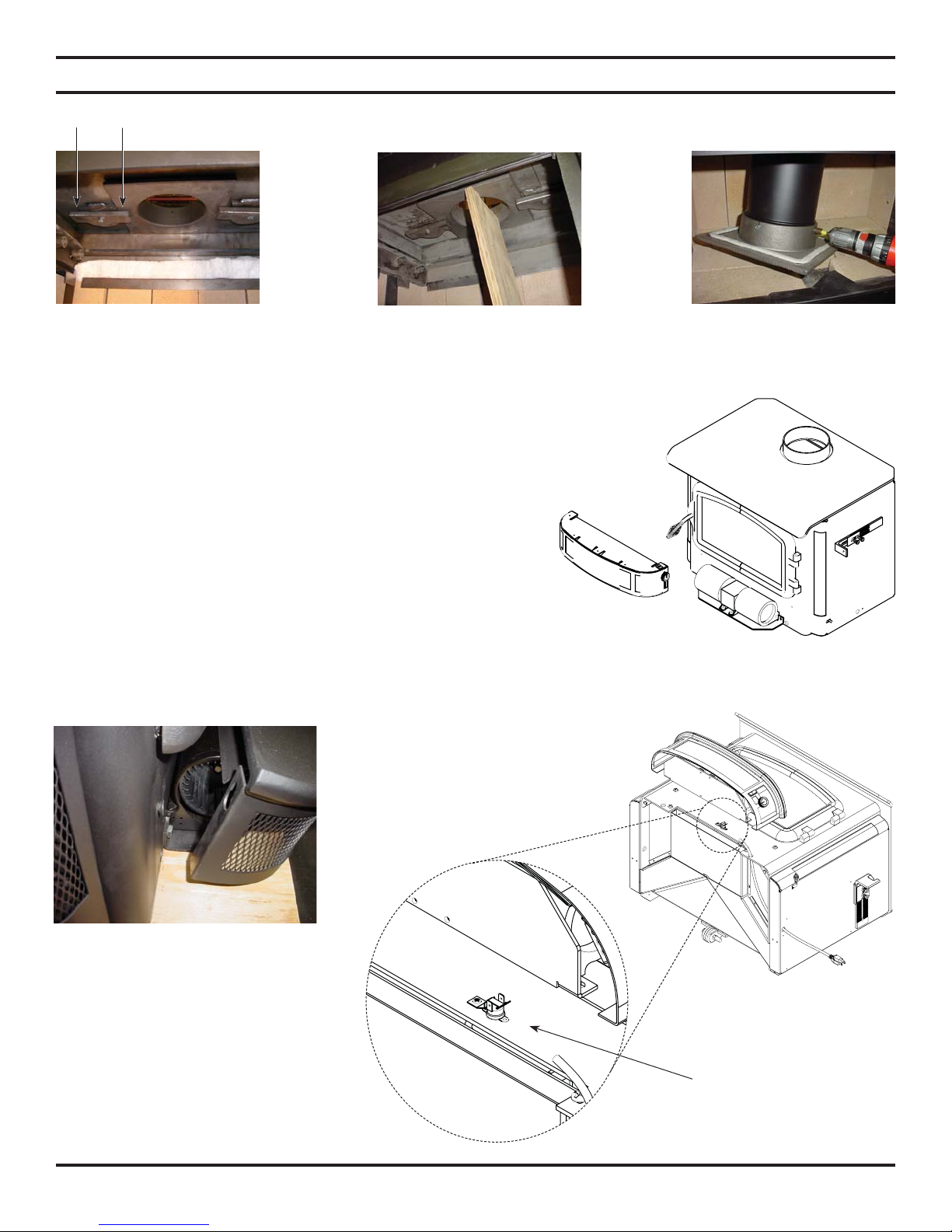
REMOVING FLUE COLLAR
REMOVING THE FLUE COLLAR
The Savannah insert has a removable fl ue collar to help with tight installations. You should
familiarize yourself with it before you install your insert.
To remove the fl ue collar you will have to remove the secondary air tubes and the C-cast
baffl e plates. See Figure 6.
1. Use a Philips head screw driver or your fi ngers to remove the drywall screws that are
hanging down next to the secondary air tubes. These screws were for shipping purposes
only and can be discarded.
2. To remove the tubes, start by removing the cotter pin on the left end of each tube, then
slide the tube to the right until the tube can be pulled down and left, and removed from
the stove. Note that each tube is marked with either M (middle) F (front) or R (rear).
Be sure you replace the tubes in their correct location to ensure your stove burns at its
optimal effi ciency. Three new cotter pins have been shipped with the insert.
3. After all three tubes have been removed you can remove the two piece C-cast baffl e.
Be very careful not to damage the baffl e. Carefully lift up on the rear piece and move it
as far back as possible letting it sit on top of the steel non-removable baffl e. Next, lift
up on the front piece and move it to the right and allow the left side to angle down into
the fi rebox until it can be removed through the door opening. You can now remove the
rear piece the same way. Figures 7 and 8.
4. Remove the bricks from the rear of the insert. This will make turning the fl ue collar
with the chimney liner much easier. Figure 9.
5. The fl ue collar has two rotating cam locks that will require the use of a hammer to unlock
and lock. Figure 11 shows the direction the cams need to turn to lock and unlock. The
fl ue collar is made of cast iron and is fairly heavy so you should use something such
as a piece of wood to support it. Once the fl ue collar has been lowered into the fi rebox
you can lower the chimney liner into the collar and fasten it with screws (see Figure
13). When putting the fl ue collar with the liner back in place, make sure the ceramic
gasket is in place. Use only high temp ceramic fi ber gaskets available at your Lexington
Forge dealer. NOTE: The fl ue collar has one side about ½" shorter than the other
three. This shorter side must be installed toward the rear of the fi rebox. Raise the
fl ue collar chimney assembly and support it in place. Carefully hammer the cam locks
over the fl ue collar alternating from one side to the other until they are parallel to the
back of the stove.
6. Replace the C-cast baffl e and tubes, remembering to check each tube for the
letter M, F or R to be sure you replace them in the correct location. After
the tubes are in place check to see that the c-cast baffl e is slid back against
the steel non- removable baffl e as shown in Figure 10. Replace the rear
bricks.
SECONDARY
AIR TUBES
C-CAST
BAFFLE
Figure 6
Figure 7
Figure 8
Non-removable
baffl e
C-Cast baffl e
Figure 9: Removing Firebrick
8 63D4004
1
2
Figure 10
OFF ON
FAN WIRING CONVERSION
Figure 11
Figure 12
FAN WIRING CONVERSION FROM RIGHT TO LEFT
1. Remove ash lip and shroud by lifting straight up. NOTE: The ash
lip and shroud are held in place by a keyhole slot and bolt system.
Lifting up on the ash lip allows the bolt head to slip through the
keyhole.
2. Disconnect ground from side of insert and unplug spade connectors from plug wire.
3. Feed wire through holes in side and front of insert. (Be sure to
leave it connected to the fan.) Push wire through opposite side,
reconnecting ground and plug wires.
Figure 13
Figure 14
Figure 15—The ash lip and
shroud are held in place by a
keyhole slot and bolt system.
Lifting up on the ash lip allows
the bolt head to slip through
the key hole.
63D4004 9
Figure 16—As seen from
bottom.
Snapstat
 Loading...