

Lexington Forge LX32DV, LX36DV Installation And Operating Instructions Manual
LEXINGTON FORGE
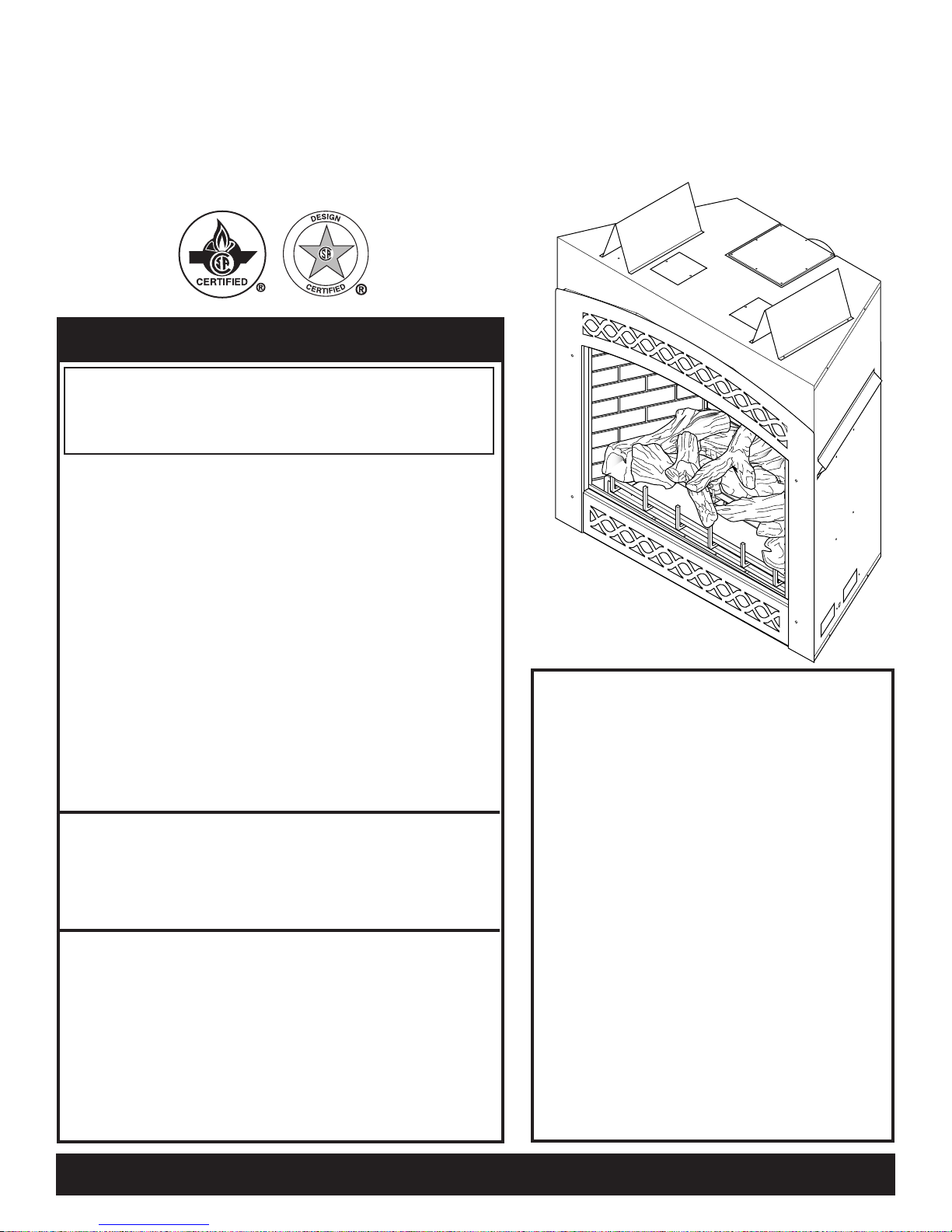
LEXINGTON DIRECT VENT GAS FIREPLACE
INSTALLATION AND OPERATING INSTRUCTIONS
MODELS:
LX32DV
LX36DV
IF THE INFORMATION IN THESE INSTRUCTIONS ARE
NOT FOLLOWED EXACTLY, A FIRE OR EXPLOSION
MAY RESULT CAUSING PROPERTY DAMAGE,
PERSONAL INJURY OR LOSS OF LIFE.
– Do not store or use gasoline or other flammable
vapors and liquids in the vicinity of this or any
other appliance.
– WHAT TO DO IF YOU SMELL GAS
• Do not try to light any appliance.
• Do not touch any electrical switch; do not use
any phone in your building.
• Immediately call your gas supplier from a
neighbor's phone. Follow the gas supplier's
instructions.
• If you cannot reach your gas supplier, call the
fire department.
– Installation and service must be performed
by a qualified installer, service agency or the
gas supplier.
WARNING: Improper installatio n, adjustment ,
alteration, services or maintenance can cause injury or
property damage. Refer to this manual. For assistance
or additional information consult a qualified installer,
service agency or the gas supplier.
This appliance is only for use with the type of gas
indicated on the rating plate. This appliance is
not convertible for use with other gases, unless a
certified kit is used.
This appliance may be installed in an aftermarket*,
permanently located, manufactured home, where not
prohibited by local codes.
*Aftermarket: Completion of sale, not for purpose of resale, from
the manufacturer.
WARNINGS
DUE TO HIGH TEMPERATURES, THE
APPL I A NCE SHOULD BE LOCATED
OU T OF TRAFFIC AND AWAY FROM
FURNITURE AND DRAPERIES.
CHI L DREN AN D AD ULTS SHO U LD
BE ALERTED TO THE HAZARDS OF
HIGH SURFACE TEMPERATURE AND
SHOULD STAY AWAY TO AVOID BURNS
OR CLOTHING IGNITION.
Y O U N G C H I L D R EN S H O UL D B E
SUPERVISED WHEN THEY ARE IN THE
SAME ROOM AS THE APPLIANCE.
CL OTHING OR OTHE R FLAMMABLE
MATERIAL SHOULD NOT BE PLACED ON
OR NEAR THE APPLIANCE.
KEEP THE ROOM AREA CLEAR AND
FREE FROM COMBUSTIBLE MATERIALS,
GASOLINE, AND OTHER FLAMMABLE
VAPORS AND LIQUIDS.
READ BEFORE INSTALLING. SAVE THESE INSTRUCTIONS

CONTENTS
CONGRATULATIONS!
You have purchased a state-of-the-art gas appliance featuring the LEXFIRE BURN SYSTEM™
technology available exclusively on Lexington Forge gas appliances.
The LEXFIRE BURN SYSTEM™ technology sets a new standard for flame appearance through
loginnovative design, burner technology and ember placement. Each element effecting
combustionandflame appearance was carefully scrutinized and strategically
balancedduringthedesignprocess to provide a product that was truly
“BORN TO BURN.”
Important Safety Information .......................... 3
Product Features .............................................. 5
Code Approval .................................................. 5
Pre-Installation Information
Installing Above 2000 Feet ............................ 6
Orifice Sizes, Pressures and BTUs ............... 6
Before You Install .......................................... 6
Fireplace Framing ......................................... 7
LX32 Fireplace Dimensions .......................... 8
LX36 Fireplace Dimensions .......................... 9
Fireplace Location ....................................... 10
Clearances .......................................................11
Securing Fireplace to Floor or Framing ....... 12
Installation Information .................................. 13
Vent Installation .............................................. 14
Combustible Clearances for Vent Pipe ....... 14
Optional Top Vent Application ..................... 15
Installation Planning .................................... 16
How to Use the Vent Graph ........................ 18
Rear Wall Vent Installation .......................... 19
Horizontal (Through the Wall) Termination
Configuration ............................................... 21
Below Grade Installation ............................. 23
Vertical Through-the-Roof Installation ......... 24
Installation for Vertical Termination ............. 25
Checking Gas Pressure ................................. 29
Electrical Installation ..................................... 30
Electrical Wiring .......................................... 30
Remote Wall Switch .................................... 30
Glass Removal ................................................ 31
Log Placement ................................................ 32
Air Restrictor Adjustment .............................. 35
Facing Installation .......................................... 36
Operating Instructions ................................... 37
What To Do If You Smell Gas ...................... 37
Lighting Pilot for the First Time ................... 37
Lighting Pilot ............................................... 38
Lighting Burner ............................................ 39
To Turn Off Gas ........................................... 39
Maintenance .................................................... 40
Venting System ........................................... 40
Cleaning Glass ............................................ 40
Pilot and Burner Flames ............................. 40
Firebox Cleaning ......................................... 40
Glass Replacement ........................................ 41
Blower.............................................................. 41
Replacement Parts ......................................... 42
Optional Accessories ..................................... 44
Fireplace Installation ...................................... 27
Check Gas Type .......................................... 27
Installing Gas Piping to Fireplace/Burner
System Location ......................................... 27
2 51D0528
Troubleshooting ............................................. 46
Warranty ...........................................Back Cover

IMPORTANT SAFETY INFORMATION
INSTALLER
Please leave these instructions with the owner.
• Read this owner’s manual carefully and completely before trying to assemble, operate,
or service this fireplace.
• Any change to this fireplace or its controls can be dangerous.
• Improper installation or use of this fireplace can cause serious injury or death from
WARNING
fire, burns, explosions, electrical shock and carbon monoxide poisoning.
This fireplace is a vented product. This fireplace must be properly installed by a qualified service person. The glass door
must be properly seated and sealed. If this unit is not properly
installed by a qualified service person with glass door properly
seated and sealed, combustion leakage can occur.
CARBON MONOXIDE POISONING: Early signs of
carbon monoxide poisoning are similar to the flu with headaches, dizziness and/or nausea. If you have these signs, the
fireplace may not have been installed properly. Get fresh air
at once! Have the fireplace inspected and serviced by a qualified service person. Some people are more affected by carbon
monoxide than others. These include pregnant women, people
with heart or lung disease or anemia, those under the influence
of alcohol, and those at high altitudes.
Propane/LP gas and natural gas are both odorless. An odormaking agent is added to each of these gases. The odor helps
you detect a gas leak. However, the odor added to these gases
can fade. Gas may be present even though no odor exists.
Make certain you read and understand all warnings. Keep
this manual for reference. It is your guide to safe and proper
operation of this fireplace.
1. This appliance is only for use with the type of gas indi
cated on the rating plate. This appliance is not convertible
for use with other gases unless a certified kit is used.
2. For propane/LP fireplace, do not place propane/LP supply
tank(s) inside any structure. Locate propane/LP supply
tank(s) outdoors. To prevent performance problems, do not
use propane/LP fuel tank of less than 100 lbs. capacity.
3. If you smell gas
• shut off gas supply.
• do not try to light any appliance.
• do not touch any electrical switch; do not use any
phone in your building .
• immediately call your gas supplier from a neighborʼs
phone. Follow the gas supplierʼs instructions.
OWNER
Please retain these instructions for future reference
4. Never install the fireplace
• in a recreational vehicle
• where curtains, furniture, clothing, or other flammable
objects are less than 42" from the front, top, or sides
of the fireplace
• in high traffic areas
• in windy or drafty areas
5. This fireplace reaches high temperatures. Keep children
and adults away from hot surfaces to avoid burns or clothing ignition. Fireplace will remain hot for a time after
shutdown. Allow surfaces to cool before touching.
6. Carefully supervise young children when they are in the
room with fireplace.
7. Do not modify fireplace under any circumstances. Any
parts removed for servicing must be replaced prior to
operating fireplace.
8. Turn fireplace off and let cool before servicing, install
ing, or repairing. Only a qualified service person should
install, service, or repair the fireplace. Have burner system
inspected annually by a qualified service person.
9. You must keep control compartments, burners, and cir-
culating air passages clean. More frequent cleaning may
be needed due to excessive lint and dust from carpeting,
bedding material, pet hair, etc. Turn off the gas valve and
pilot light before cleaning fireplace.
10. Have venting system inspected annually by a qualified
service person. If needed, have venting system cleaned
or repaired. See Cleaning and Maintenance, page 40.
11. Keep the area around your fireplace clear of combustible
materials, gasoline, and other flammable vapor and liquids. Do not run fireplace where these are used or stored.
Do not place items such as clothing or decorations on or
around fireplace.
Continued on page 4
.
-
51D0528 3
IMPORTANT SAFETY INFORMATION
Continued from page 3
12. Do not use this fireplace to cook food or burn paper or
other objects.
13. Never place anything on top of fireplace.
14. Do not use any solid fuels (wood, coal, paper, cardboard,
etc.) in this fireplace. Use only the gas type indicated on
rating plate.
15. This appliance, when installed, must be electrically
grounded in accordance with local codes or in the
absence of local codes, with the National Electrical
Code, ANSI/NFPA 70, or the Canadian Electrical Code,
CSA C22.1.
16. Do not obstruct the flow of combustion and ventilation
air in any way. Provide adequate clearances around
air openings into the combustion chamber along with
adequate accessibility clearance for servicing and proper
operation.
17. When the appliance is installed directly on carpeting,
tile or other combustible material other than wood flooring, you must set appliance on a metal or wood panel
or hearth pad extending the full width and depth of the
appliance.
18. Do not use fireplace if any part has been exposed to or
under water. Immediately call a qualified service person
to arrange for replacement of the unit.
19. Do not operate fireplace if any log is broken.
IMPORTANT:
PLEASE READ THE FOLLOWING CAREFULLY
It is normal for fireplaces fabricated of steel to
give off some expansion and/or contraction noises
during the start up or cool down cycle. Similar
noises are found with your furnace heat exchanger
or car engine.
IMPORTANT:
PLEASE READ THE FOLLOWING CAREFULLY
It is not unusual for gas fireplace to give off some
odor the first time it is burned. This is due to the
manufacturing process.
Please ensure that your room is well ventilated
during burn off — open all windows.
It is recommended that you burn your fireplace for
at least ten (10) hours the first time you use it. Place
the fan switch in the “OFF” position during this time.
Never connect unit to private
(non-utility) gas wells. This
gas is commonly known as
wellhead gas.
WARNING
20. Do not use a blower insert, heat exchanger insert, or
any other accessory not approved for use with this fire
place.
21. Do not operate the fireplace with glass door removed,
cracked, or broken.
22. For Massachusetts Residents Only: This product
must be installed by a licensed plumber or gas fitter when
installed within the Commonwealth of Massachusetts.
Flexline installation must not exceed 36".
4 51D0528
-
www.nficertified.org
We suggest that our gas hearth
products be installed and
serviced by professionals who
are certified in the U.S. by the
National Fireplace Institute®
(NFI) as Gas Specialists.
O
F
F
PRODUCT SPECIFICATIONS
PRODUCT FEATURES AND CODE APPROVAL
• This appliance has been certi
fied for use with either natural or
propane gas. See appropriate data
plates.
• This appliance is not for use with
solid fuels.
• The appliance is approved for
bedroom or bedsitting room
installations.
• The appliance must be installed
in accordance with local codes if
any. If none exist use the current
installation code. ANSI Z223.1/
NFPA 54 in the USA, CAN/CGA
B149 in Canada.
• This appliance is mobile home
approved.
• The appliance must be properly
connected to a venting system.
-
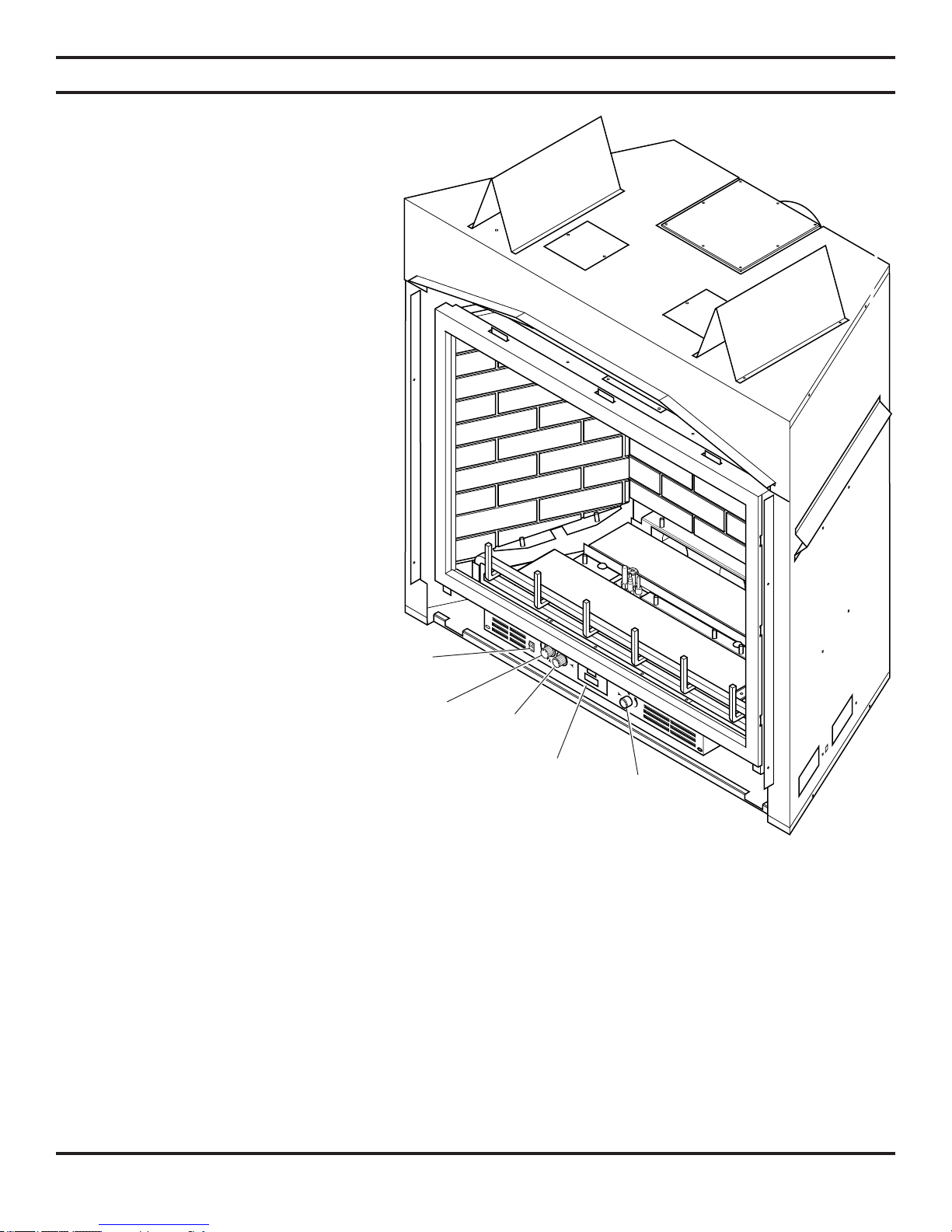
On/Off/
RS Switch
Off/Pilot/On
Knob
Hi/Lo
Knob
Optional
The efficiency rating of this appliance is
a product thermal efficiency rating deter-
Remote
Receiver
Blower
Control
mined under continuous operating conditions and was determined independently of
Figure 1 - LX32DV Fireplace
any installed system.
Thermal Efficiency = up to 80%
CODE APPROVAL
Direct Vent type appliances draw all combustion air from outside of the dwelling through the vent pipe.
These appliances have been tested by CSA and found to comply with the established standards for DIRECT VENT GAS
FIREPLACE HEATERS in the USA and Canada as follows:
LISTED VENTED GAS FIREPLACE HEATER
TESTED TO: ANSI Z21.88-2002/CSA 2.33-2002 STANDARDS
51D0528 5
PRE-INSTALLATION INFORMATION
INSTALLING ABOVE 2000 FEET
• In the USA, the appliance must be derated 4% for every 1,000 ft above 2,000 ft elevations.
• In Canada, these appliances are certified for altitudes of 0 – 2000 ft, and must be de-rated by 10 percent for installations
between 2000 and 4,500 ft. (derate an additional 4% for every 1,000 ft. above 4,500 ft. elevations).
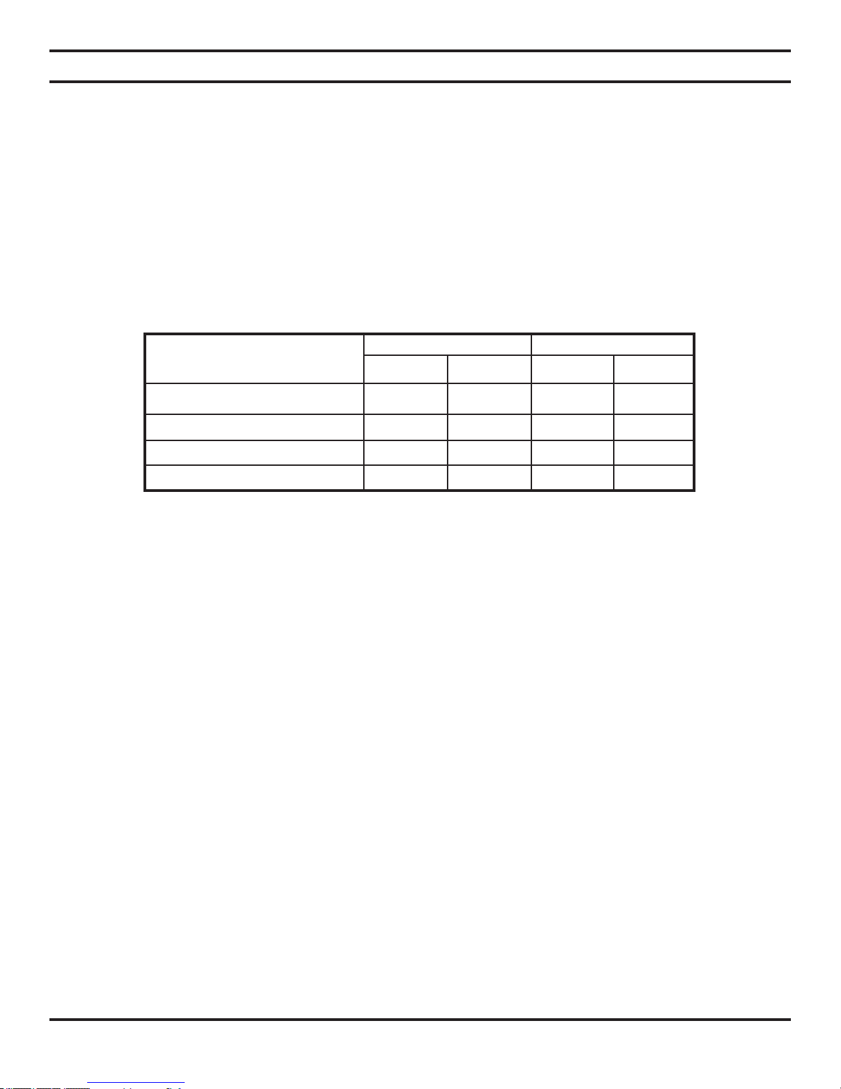
ORIFICE SIZES, PRESSURES AND BTUs
NATURAL GAS PROPANE GAS
Manifold Press: (W.C.) 3.5" Manifold Press: (W.C.) 10"
Maximum Supply Pressure 10.5" Maximum Supply Pressure 13"
Minimum Supply Pressure 4.5" Minimum Supply Pressure 11"
Model Number LX32 LX36
NATURAL PROPANE NATURAL PROPANE
Max. Btu/hr Input 36000 36000 44000 44000
Min. Btu/hr Input 26000 22000 30000 32000
Orifice size (as shipped) Front #46 #
3
/64 #41 #55
Orifice size (as shipped) Rear #43 #55 #38 #53
BEFORE YOU START
Read this homeowner manual thoroughly and follow all instructions carefully. Inspect all contents for shipping damage and
immediately inform your dealer if any damage is found. Do not install any unit with damaged, incomplete, or substitute parts.
Check your packing list to verify that all listed parts have been received. You should have the following:
• Fireplace (Firebox and Burner System) • Log Set
• Propane Conversion Kit • Rock Wool
• Deflector Shield (to be used with Simpson Horizontal Termination – P/N 985)
ITEMS REQUIRED FOR INSTALLATION
Tools: Building Supplies:
• Phillips Screwdriver • Framing Materials
• Hammer • Wall Finishing Materials
• Saw and/or saber saw • Caulking Material (Noncombustible)
• Level • Fireplace Surround Material (Noncombustible)
• Measuring Tape • Piping Complying with Local Codes
• Electric Drill and Bits • Tee Joint
• Pliers • Pipe Sealant Approved for use with Propane/LPG
• Square (Resistant to Sulfur Compounds)
• Pipe Wrench
6 51D0528
C
H
A
E
D
G
F
1"
GAP
1"
GAP
B
A
C
G
A
1" GAP 1" GAP
G
A
1" GAP 1" GAP
C
PRE-INSTALLATION INFORMATION
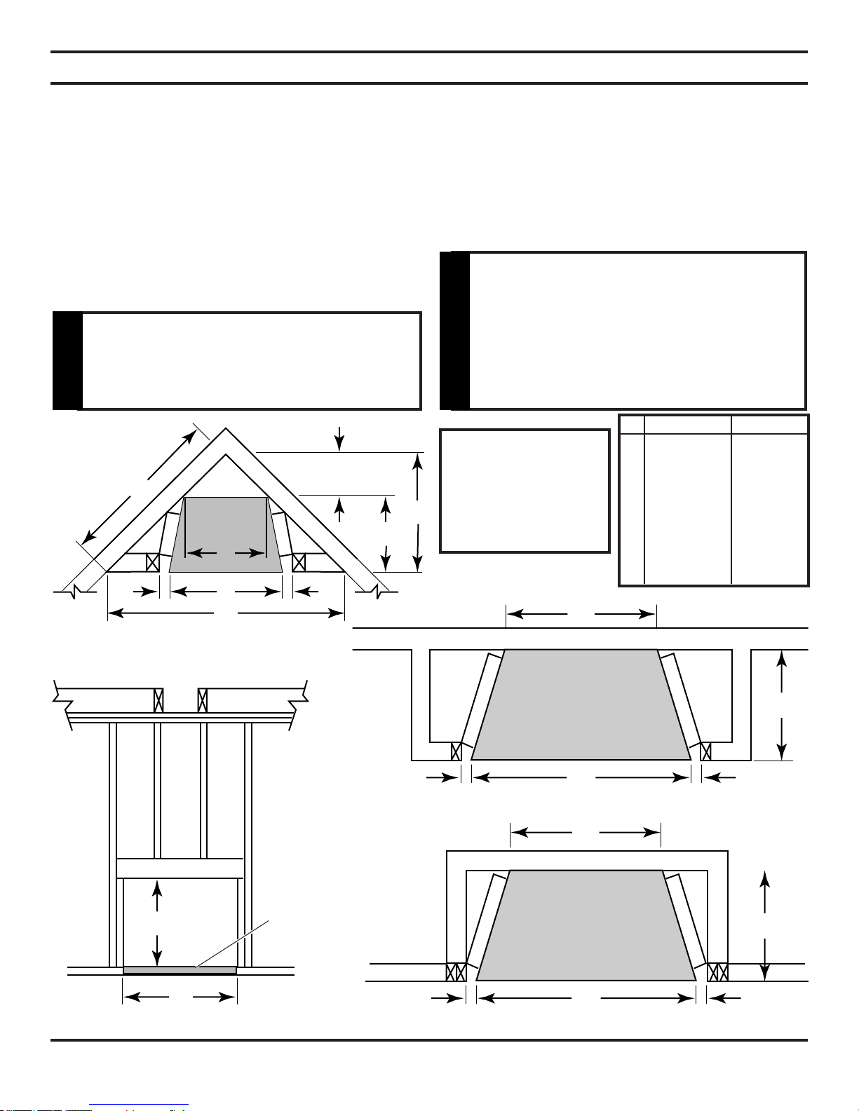
FIREPLACE FRAMING
Firebox framing can be built before or after the appliance is set in place. Construct firebox framing following Figures 2
through 5 and the chart below for your specific installation requirements. See Pages 8 and 9 for firebox dimensions. The
framing headers may rest on the top of the firebox standoffs.
The firebox may be installed directly on a combustible floor or raised on a platform of an appropriate height. When the
firebox is installed directly on carpeting, tile, or other combustible material, other than wood flooring, the firebox shall be
installed on a metal or wood panel extending the full width and depth of the enclosure.
To access control door, build a platform to make the bottom
of appliance equal to or higher than top of finished hearth
extension, or elevate unit a minimum of 7/8" above subfloor.
The 1" standoffs on back and sides
and 6" standoffs on top of fireplace
are designed to separate fireplace
from framing. These standoffs may
Do not fill spaces around firebox with
insulation or other materials. This
could cause a fire.
contact framing but no material may
be placed between standoff and side
WARNING
of fireplace.
WARNING
LX32DV LX36DV
Fireplace
must be raised
minimum 7/8"
to allow door to
open.
A 3911/16" 4311/16"
B 403/4" 463/4"
C 205/16" 245/16"
D 10" 10"
E 621/2" 661/2"
F 313/16" 331/2"
G 213/4" 213/4"
H 441/4 " 47"
Figure 2 - Corner Installation
7/8"
Minimum
Platform
Figure 4 - Stud Location
51D0528 7
Figure 3 - Inside Chase
Installation
Figure 5 - Recessed Installation
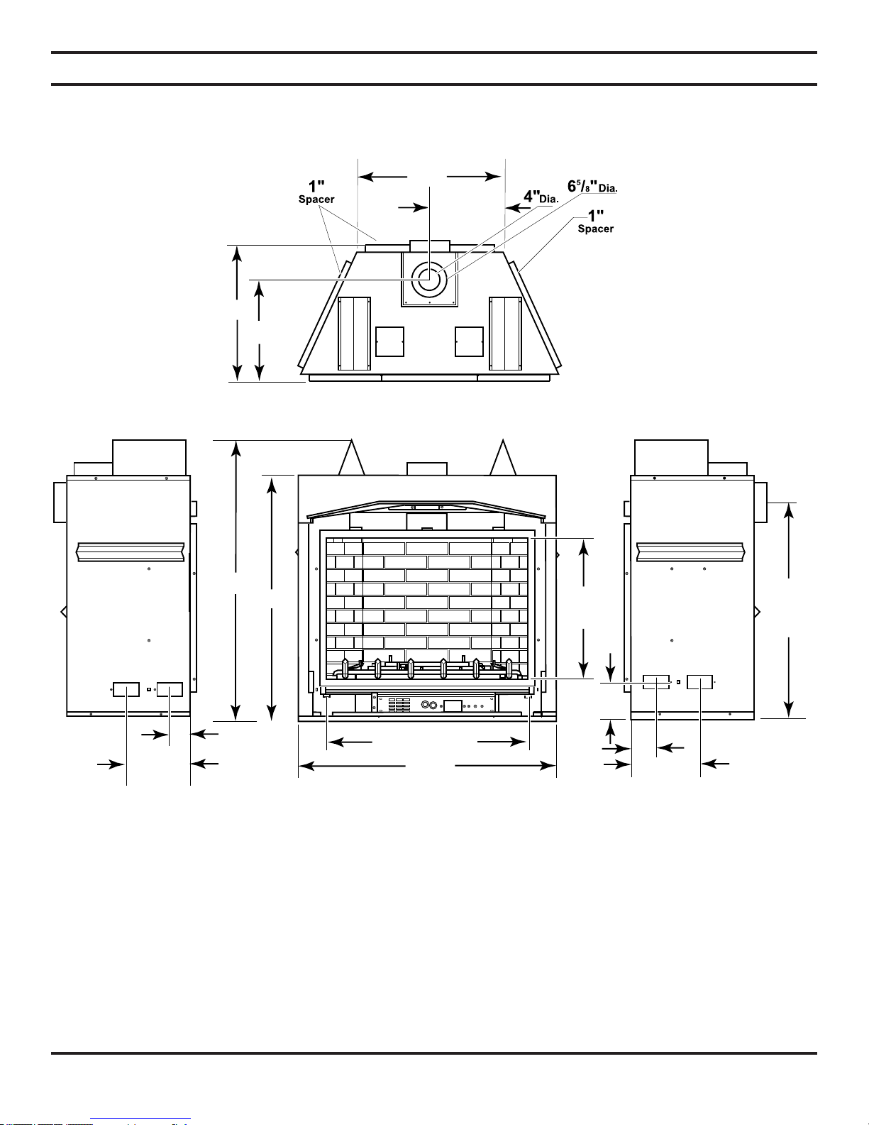
213/4"
51/4"
51/4"
213/16"
107/8" 107/8"
401/2"
313/4" - Glass
357/8"
Center
Of Pipe
24"
Glass
393/8"
205/16"
105/32"
161/2"
* Minimum 7/8" for proper door operation
*461/2"
PRE-INSTALLATION INFORMATION
LX32 FIREPLACE DIMENSIONS
Figure 6 - Fireplace Dimensions
8 51D0528
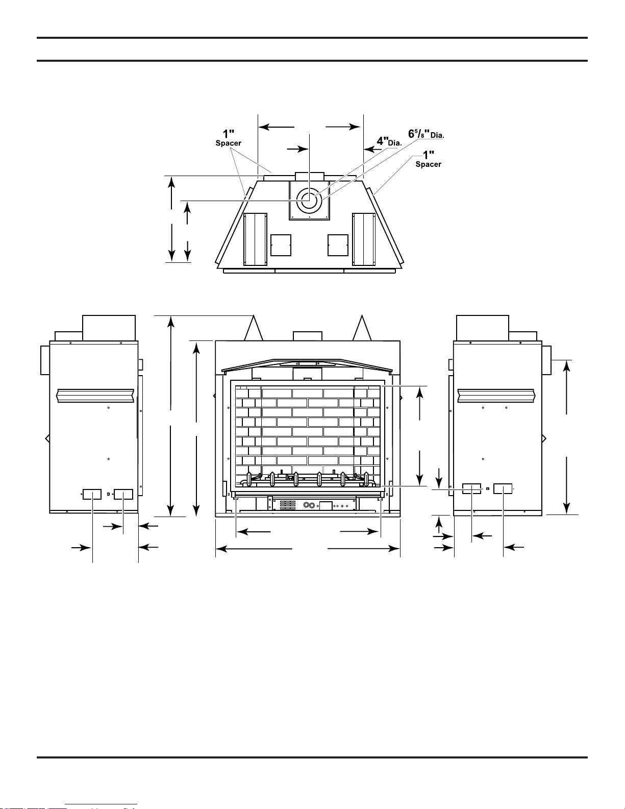
213/4"
51/4"
51/4"
213/16"
107/8" 107/8"
401/2"
333/4 - Glass"
357/8"
Center
Of Pipe
24"
Glass
433/8"
245/16"
125/32"
16"
* Minimum 7/8" for proper door operation
*461/2"
LX36 FIREPLACE DIMENSIONS
PRE-INSTALLATION INFORMATION
Figure 7 - Fireplace Dimensions
51D0528 9
Y
E
A
B
C
D
F
Y
B
X
PRE-INSTALLATION INFORMATION
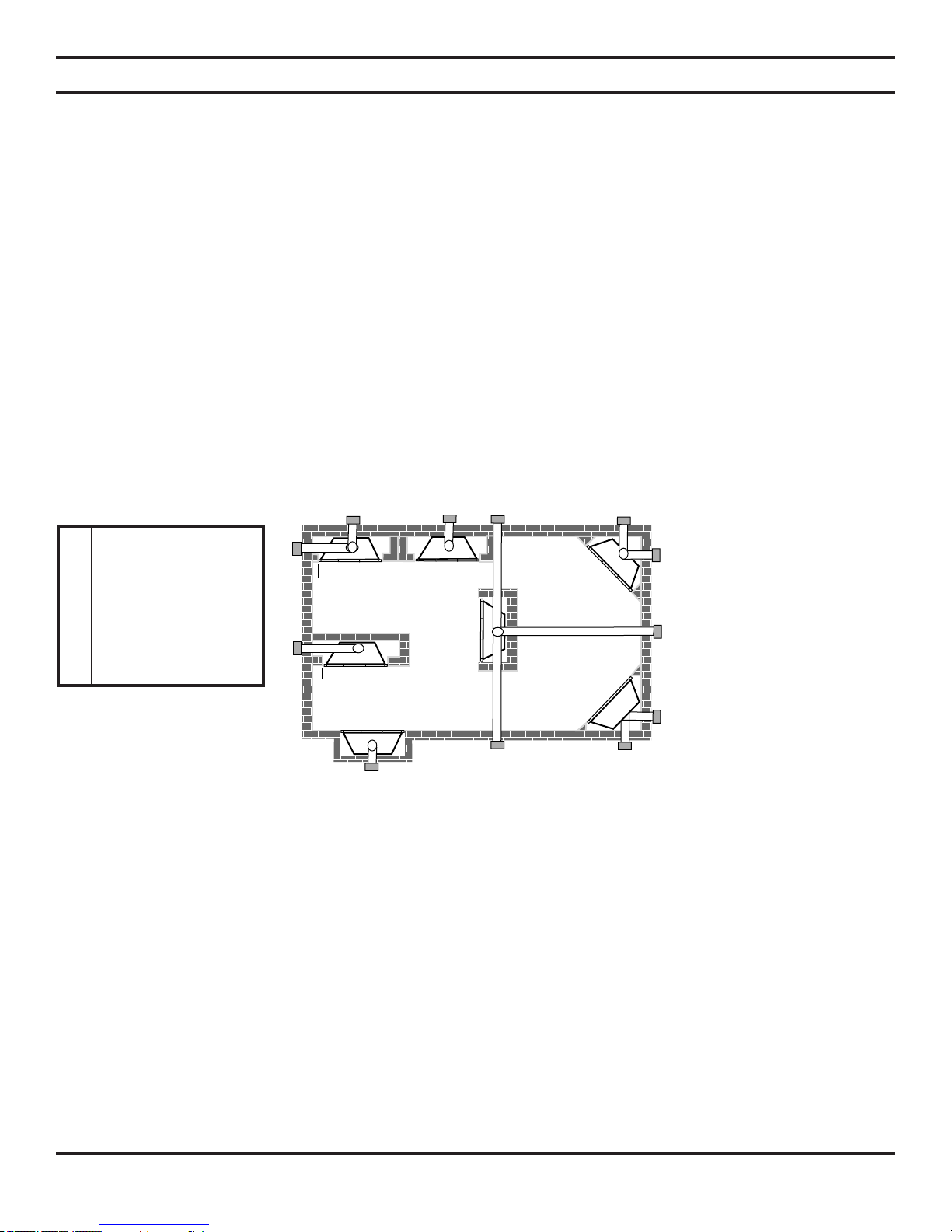
FIREPLACE LOCATION
Plan for the installation of your appliance. This includes determining where the unit is to be installed, the vent configuration
to be used, framing and finishing details, and whether any optional accessories (i.e. blower, wall switch, or remote control)
are desired. Consult your local building code agency to ensure compliance with local codes, including permits and inspections.
The following factors should be taken into consideration:
• Clearance to side-wall, ceiling, woodwork, and windows. Minimum clearances to combustibles must be maintained.
• This fireplace may be installed along a wall, across a corner, or use an exterior chase. See Figure 8 for suggested loca-
tions.
• Location should be out of high traffic areas and away from furniture and draperies due to heat from appliance.
• Never obstruct the front opening of the fireplace.
• Do
not install in the vicinity where gasoline or other flammable liquids may be stored.
• Vent pipe routing. See VENTING section found in this manual for allowable venting configurations.
• These units can be installed in a bedroom. See National Fuel Gas Code ANSI Z233.1/NFPA 54 — (current edition), the
Uniform Mechanical Code — (current edition), and Local Building Codes for specific installation requirements.
A Flat on Wall
B Cross Corner
C Island**
D Room Divider*
E Flat on Wall Corner*
F Chase Installation
Y 9" Minimum
Figure 8 - Locating Gas Fireplace
** Island (C) and room divider (D) installation is possible as long as the horizontal portion of vent system (X)
does not exceed 20'. See Installing Horizontal Termination Configuration on pages 20 and 21.
* When you install your fireplace in (D) room divider or (E) flat on wall corner positions (Y), a minimum of 6"
clearance must be maintained from perpendicular wall and front of fireplace.
10 51D0528
O
F
F
SECURING FIREPLACE TO FLOOR OR FRAMING
The fireplace must be secured to the floor and/or to framing studs as shown in Figure 9. Use two (2) wood screws or masonry/
concrete screws to secure fireplace to the floor. Use four (4) screws to attach fireplace to framing. The side brackets are
adjustable from 1/2" to 5/8" to accommodate different thickness of noncombustible material.
Framing
Adjustable
Bracket
NOTE: Do not
allow combustibles
(drywall) to touch
top and side edges
of black-painted
metal face of
fireplace. Only use
noncombustibles.
A 4" wide or more
cement board may
touch the top and
side edges of blackpainted metal face of
fireplace.
Screws
Framing
Do not allow any
combustible to
overlap the blackpainted face of
fireplace.
Screws
Figure 9 - Securing Fireplace to Floor and Framing Studs
Adjustable
Bracket
Screws
51D0528 11
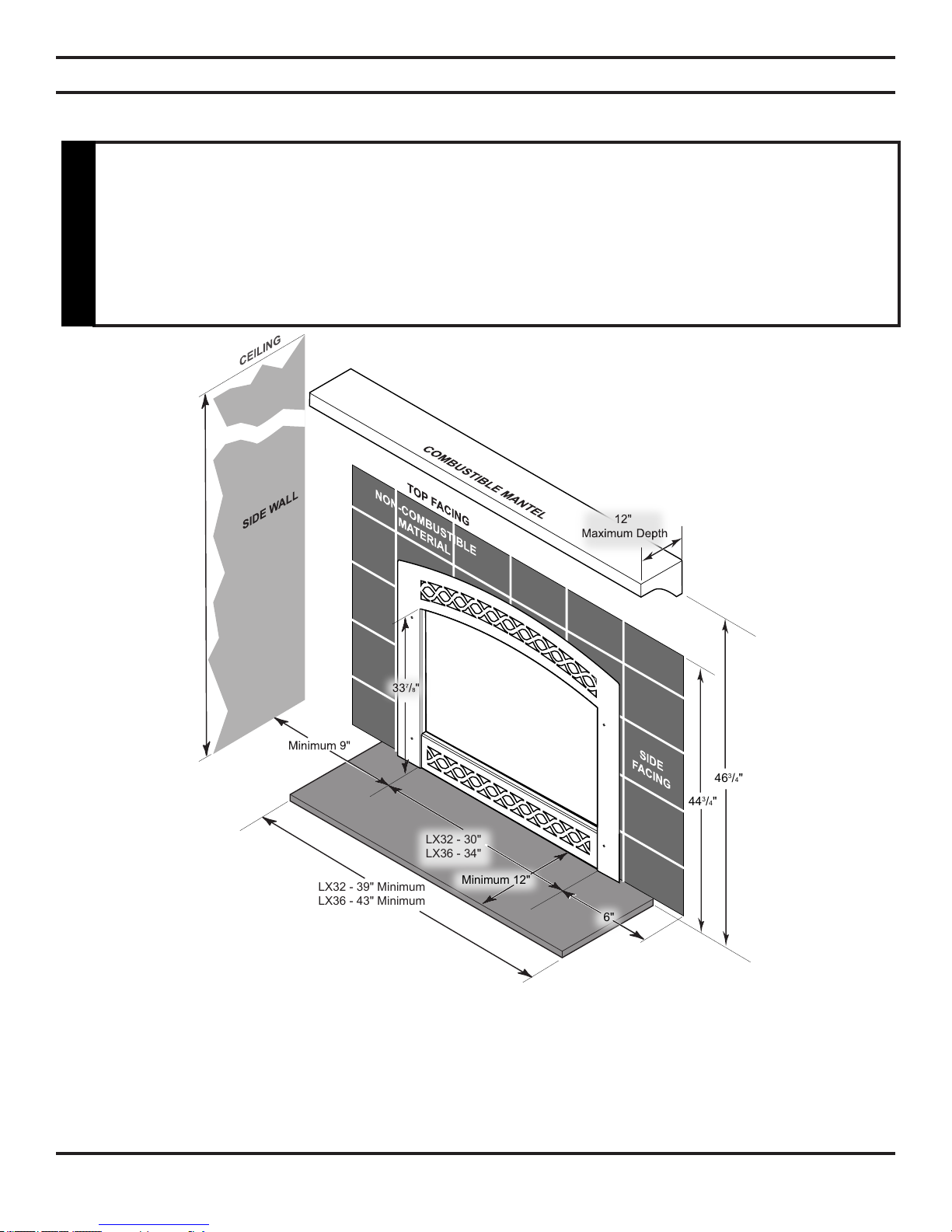
LX32 - 30"
LX36 - 34"
LX32 - 39" Minimum
LX36 - 43" Minimum
Minimum 12"
443/4"
463/4"
6"
CLEARANCES
CLEARANCES TO COMBUSTIBLES
Follow these instructions carefully to ensure safe installation. Failure to follow
instructions exactly can create a fire hazard.
The appliance cannot be installed on a carpet, tile or other combustible material other
than wood flooring. If installed on carpet or vinyl flooring, the appliance shall be installed
on a metal, wood or noncombustible material panel extending full width and depth of
WARNING
the appliance.
Figure 10 - Clearances
MANTEL CLEARANCES
NOTE: The combustible area above the facing must not protrude more than 3/4" from the facing. If it does,
it is considered a mantel and must meet the mantel requirements listed in this manual.
HEARTH REQUIREMENTS
The fireplace must be installed on a non-combustible hearth extending a minimum of 12" from the fireplace opening (local
codes may require a larger hearth). The hearth must also extend to both sides of the face (see the table above for the exact
width of the face).
12 51D0528
INSTALLATION INFORMATION
FINISHING MATERIAL
NOTE: Any remote wiring (i.e. remote control, wall switch, and optional fan) must be done prior to final
finishing to avoid costly reconstruction.
Never obstruct or modify the air inlet or outlet grills (louvers). This may create a
fire hazard.
WARNING
Only noncombustible materials (i.e. brick, tile, slate, steel, or other materials with a UL fire rating of Zero) may be used to cover the
black surface of the appliance. A 300
the finished wall and the fireplace surround are sealed, a 300
be used.
VENT INSTALLATION
°F minimum adhesive may be used to attach facing materials to the black surface. If joints between
°F minimum sealant material (General Electric RTV103 or equivalent) must
Read all instructions completely and thoroughly before attempting installation. Failure
to do so could result in serious injury, property damage or loss of life. Operation of
improperly installed and maintained venting system could result in serious injury,
property damage or loss of life.
WARNING
Failure to follow these instructions will
void the warranty.
NOTICE
INSTALLATION PRECAUTIONS
Consult local building codes before beginning the installation. The installer must make sure to select the proper vent system
for installation. Before installing vent kit, the installer must read this fireplace manual and vent kit instructions.
Only a qualified installer/service person should install venting system. The installer must follow these safety rules:
• Wear gloves and safety glasses for protection.
• Use extreme caution when using ladders or when on rooftops.
• Be aware of electrical wiring locations in walls and ceilings.
The following actions will void the warranty on your venting system:
• Installation of any damaged venting component.
• Unauthorized modification of the venting system.
• Installation of any component part not manufactured or approved by Lexington Forge.
• Installation other than permitted by these instructions.
51D0528 13
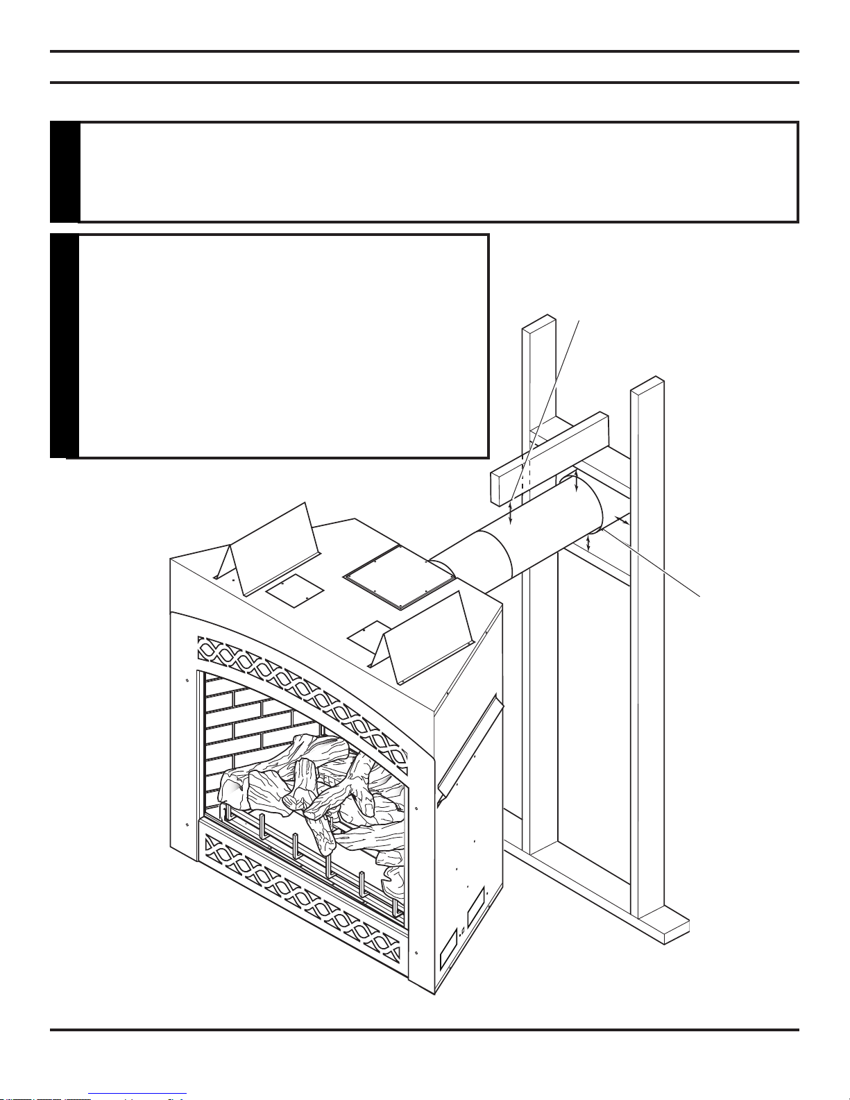
VENT INSTALLATION
COMBUSTIBLE CLEARANCES FOR VENT PIPE
This fireplace must be vented to the outside. The venting system must NEVER be
attached to a chimney serving a separate solid fuel burning appliance. Each gas
appliance must use a separate vent system. Do not use common vent systems.
WARNING
Horizontal sections of this vent system require
a minimum of 3" clearances to combustibles at
the top of the flue and 1" clearance at the sides
and bottom until the flue penetrates the outside
wall. A minimum 1" clearance all around the flue
is acceptable at this point of penetration.
Vertical sections of this vent system require a
minimum of 1" clearance to combustibles on all
sides of the pipe.
A Minimum of 3" Clearance
to the Top Is Required Along
Horizontal Length until Flue
Pipe Penetrates Outside Wall.
A Minimum 1"
Clearance to
Combustibles
Permitted All
Around Flue
at Outside
Wall
Figure 11 - Combustible Clearances for Vent Pipe
14 51D0528
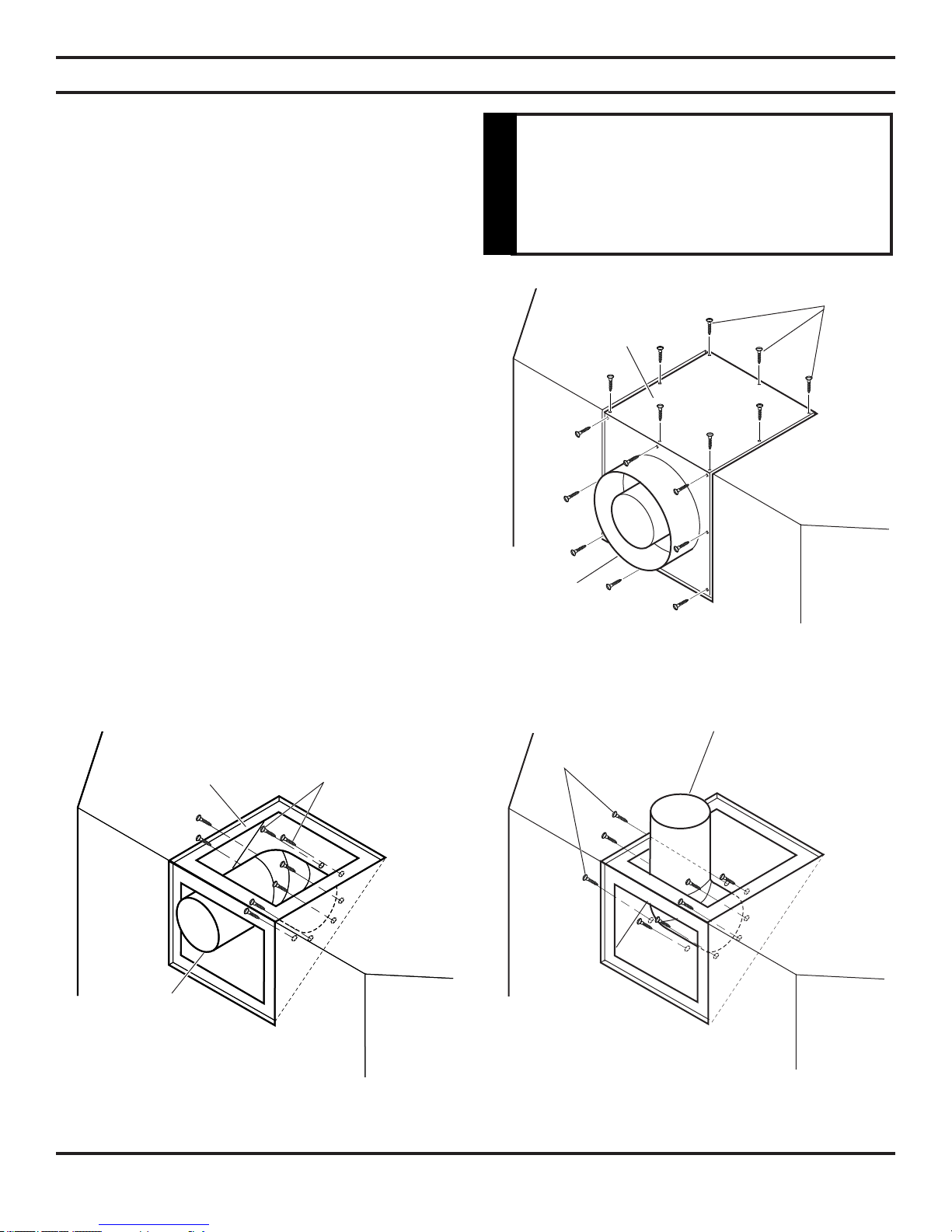
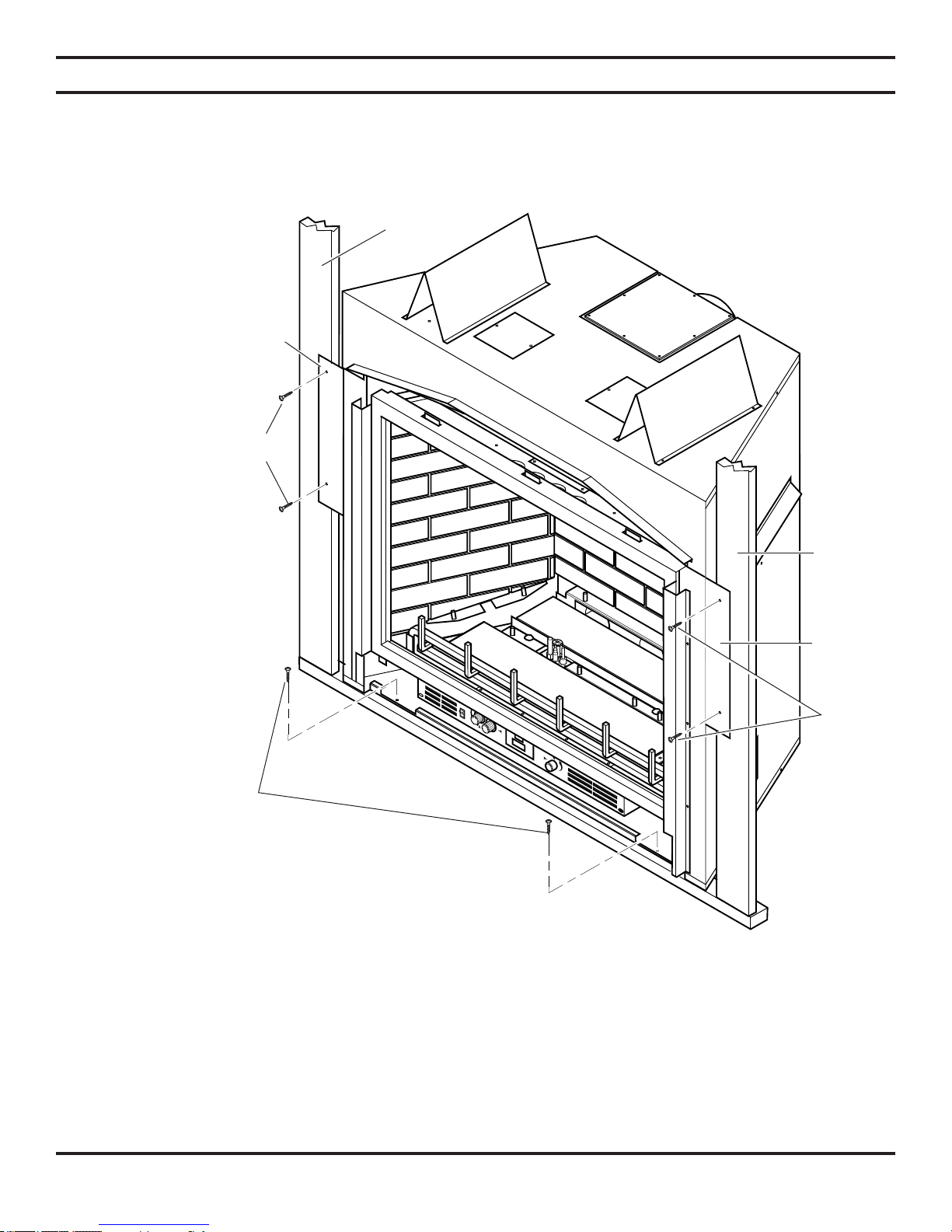
OPTIONAL TOP VENT APPLICATION
VENT INSTALLATION
The appliance is shipped as a rear vent unit. If the installation layout requires the unit to be a top vent configuration the
appliance can be converted by the following steps.
When removing and refitting the plates and adapter be sure the
associated gaskets are undamaged and refitted as required.
1. Remove the eight (8) screws securing the flue pipe adapter
to the fireplace body.
2. Set the flue pipe adapter aside, complete with the gasket.
Do not damage the gaskets as the adapter and gasket must
be refitted.
3. Remove the eight (8) screws securing the flue pipe cover to
the top of the intake box and remove the cover and gasket.
See Figure 12.
4. Remove eight (8) screws securing the flue pipe to the back
of the intake box and remove the pipe and gasket.
Figure 13.
5. Replace flue pipe to top of firebox. Ensure the gasket is in
place and undamaged. Secure with eight (8) screws. See
Figure 13.
6. Place the flue pipe cover and gasket removed in step 3 over
the flue opening in bottom of the intake box.
See Figure 12.
See
A f t er c o n ve rs i on to to p v e nt
configuration the 4" (100mm) flue pipe
should be concentric within the 6
(175mm) outer collar (within 1/4").
WARNING
Flue Pipe
Cover
Flue Pipe
Adapter
5
/8"
Screws
7. Refit the flue pipe adapter and gasket to the top of fire
place. Secure the adapter with eight (8) screws removed
in step 1.
Flue
Cover
Flue Pipe
Screws
-
Figure 12 - Removing sixteen (16) Screws from
Flue Pipe Adapter and Flue Pipe Cover
Flue Pipe
Screws
Figure 13 - Removing Flue Pipe
51D0528 15
Figure 14 - Attaching Flue Pipe to Top
Vent Configurations
 Loading...