

Lexington Forge CSDV20SNV, CSDV30SNV, CSDV40SNV, CSDV20DNV, CSDV30DNV Installation And Operating Instructions Manual
...
INST ALLATION AND OPERATING
MODELS:
CSDV20SNV CSDV30SNV CSDV40SNV
CSDV20DNV CSDV30DNV CSDV40DNV
CSDV20SLP CSDV30SLP CSDV40SLP
CSDV20DLP CSDV30DLP CSDV40DLP
WARNINGS
IF THE INFORMA TION IN THESE INSTRUCTIONS ARE
NOT FOLLOWED EXACTLY, A FIRE OR EXPLOSION
MAY RESULT CAUSING PROPERTY DAMAGE,
PERSONAL INJURY OR LOSS OF LIFE.
– Do not store or use gasoline or other fl ammable
vapors and liquids in the vicinity of this or any
other appliance.
DIRECT VENT GAS
STOVE
INSTRUCTIONS
ON
OFF
– WHAT TO DO IF YOU SMELL GAS
• Do not try to light any appliance.
• Do not touch any electrical switch; do not use
any phone in your building.
• Immediately call your gas supplier from a
neighbor's phone. Follow the gas supplier's
instructions.
• If you cannot reach your gas supplier, call the
fi re department.
– Installation and service must be performed
by a qualifi ed installer, service agency or the
gas supplier.
WARNING: Improper installation, adjustment,
alteration, services or maintenance can cause injury or
property damage. Refer to this manual. For assistance
or additional information consult a qualifi ed installer,
service agency or the gas supplier.
This appliance is only for use with the type of gas
indicated on the rating plate. This appliance is
not convertible for use with other gases, unless a
certifi ed kit is used.
This appliance may be installed in an aftermarket*,
permanently located, manufactured home, where not
prohibited by local codes.
*Aftermarket: Completion of sale, not for purpose of resale, from
the manufacturer.
DUE TO HIGH TEMPERATURES, THE
APPLIANCE SHOULD BE LOCATED
OUT OF TRAFFIC AND AWAY FROM
FURNITURE AND DRAPERIES.
CHILDREN AND ADULTS SHOULD
BE ALERTED TO THE HAZARDS OF
HIGH SURFACE TEMPERATURE AND
SHOULD STAY AWAY TO AVOID BURNS
OR CLOTHING IGNITION.
YOUNG CHILDREN SHOULD BE
SUPERVISED WHEN THEY ARE IN THE
SAME ROOM AS THE APPLIANCE.
CLOTHING OR OTHER FLAMMABLE
MA TERIAL SHOULD NOT BE PLACED ON
OR NEAR THE APPLIANCE.
KEEP THE ROOM AREA CLEAR AND
FREE FROM COMBUSTIBLE MA TERIALS,
GASOLINE, AND OTHER FLAMMABLE
V APORS AND LIQUIDS.
READ BEFORE INSTALLING. SAVE THESE INSTRUCTIONS

CONTENTS
CONGRATULATIONS!
You have purchased a state-of-the-art gas appliance featuring the Lex-Fire Burn System
available exclusively on Lexington Forge gas appliances.
The Lex-Fire Burn System sets a new standard for fl ame appearance through innovative log
design, burner technology and ember placement. Each element effecting combustion and
fl ame appearance was carefully scrutinized and strategically balanced during the design
process to provide a product that was truly
“BORN TO BURN.”
Important Safety Information ..........................3
Product Features .............................................. 5
Code Approval ..................................................5
Pre-Installation Information
Installing Above 2000 Feet ............................ 6
Orifi ce Sizes, Pressures and BTUs ............... 6
Stove Dimensions ......................................... 7
Stove Location .............................................. 8
Clearances ........................................................ 9
Vent Installation .............................................. 12
Installation Precautions ............................... 12
Installation Planning .................................... 13
Installation for Horizontal Termination ......... 14
Installation for Vertical Termination ............. 20
Stove Installation
Check Gas Type .......................................... 24
Installing Gas Piping to Stove Location....... 24
Checking Gas Pressure ................................. 26
Electrical Installation...................................... 27
Electrical Wiring ..........................................27
Remote Wall Switch .................................... 27
Operating Instructions ................................... 31
What To Do If You Smell Gas ...................... 31
Lighting Pilot for the First Time....................32
Lighting Pilot................................................ 32
Lighting Burner ............................................ 33
To Turn Off Gas ........................................... 33
Cleaing and Maintenance .............................. 34
Venting System ........................................... 34
Cleaning Glass ............................................ 34
Pilot and Burner Flames.............................. 34
Firebox Cleaning ......................................... 34
Air Shutter Adjustment .................................. 35
Glass Replacement ........................................ 36
Replacement Parts ......................................... 37
CSDV20 ..................................................... 37
CSDV30 ...................................................... 39
CSDV40 ...................................................... 41
Troubleshooting .............................................43
Installation Records ....................................... 44
Mass Residents Only ..................................... 45
Warranty ...........................................Back Cover
Log and Rock Wool Placement ..................... 28
2 58D6056
IMPORTANT SAFETY INFORMATION
INSTALLER
Please leave these instructions with the appliance.
• Read this owner’s manual carefully and completely before trying to assemble, operate,
or service this stove.
• Any change to this stove or its controls can be dangerous.
• Improper installation or use of this stove can cause serious injury or death from fi re,
WARNING
burns, explosions, electrical shock and carbon monoxide poisoning.
This stove is a vented product. This stove must be properly
installed by a qualified service person. The glass door must be
properly seated and sealed. If this unit is not properly installed
by a qualified service person with glass door properly seated
and sealed, combustion leakage can occur.
CARBON MONOXIDE POISONING: Early signs of
carbon monoxide poisoning are similar to the flu with headaches, dizziness and/or nausea. If you have these signs, the
stove may not have been installed properly. Get fresh air at
once! Have the stove inspected and serviced by a qualified
service person. Some people are more affected by carbon
monoxide than others. These include pregnant women, people
with heart or lung disease or anemia, those under the influence
of alcohol, and those at high altitudes.
Propane/LP gas and natural gas are both odorless. An odormaking agent is added to each of these gases. The odor helps
you detect a gas leak. However, the odor added to these gases
can fade. Gas may be present even though no odor exists.
Make certain you read and understand all warnings. Keep
this manual for reference. It is your guide to safe and proper
operation of this stove.
1. This appliance is only for use with the type of gas indicated on the rating plate. This appliance is not convertible
for use with other gases unless a certified kit is used.
2. For propane/LP stove, do not place propane/LP supply
tank(s) inside any structure. Locate propane/LP supply
tank(s) outdoors. To prevent performance problems, do not
use propane/LP fuel tank of less than 100 gal. capacity.
3. If you smell gas
• shut off gas supply.
• do not try to light any appliance.
• do not touch any electrical switch; do not use any
phone in your building .
• immediately call your gas supplier from a neighbor’s
phone. Follow the gas supplier’s instructions.
OWNER
Please retain these instructions for future reference
4. Never install the stove
• in a recreational vehicle
• where curtains, furniture, clothing, or other flammable
objects are less than 42" from the front, top, or sides
of the stove
• in high traffic areas
• in windy or drafty areas
5. This stove reaches high temperatures. Keep children and
adults away from hot surfaces to avoid burns or clothing
ignition. Stove will remain hot for a time after shutdown.
Allow surfaces to cool before touching.
6. Carefully supervise young children when they are in the
room with stove.
7. Do not modify the burner or stove under any circum-
stances. Any parts removed for servicing must be replaced
prior to operating stove.
8. Turn stove off and let cool before servicing, installing, or
repairing. Only a qualified service person should install,
service, or repair the stove. Have burner system inspected
annually by a qualified service person.
9. You must keep control compartments, burners, and cir-
culating air passages clean. More frequent cleaning may
be needed due to excessive lint and dust from carpeting,
bedding material, pet hair, etc. Turn off the gas valve and
pilot light before cleaning stove.
10. Have venting system inspected annually by a qualified
service person. If needed, have venting system cleaned
or repaired. See Cleaning and Maintenance, page 34.
11. Keep the area around your stove clear of combustible
materials, gasoline, and other flammable vapor and liquids. Do not run burner system where these are used or
stored. Do not place items such as clothing or decorations
on or around stove.
Continued on page 4
.
58D6056 3
IMPORTANT SAFETY INFORMATION
Continued from page 3
12. Do not use this stove to cook food or burn paper or other
objects.
13. Never place anything on top of stove.
14. Do not use any solid fuels (wood, coal, paper, cardboard,
etc.) in this stove. Use only the gas type indicated on
burner system nameplate.
15. This appliance, when installed, must be electrically
grounded in accordance with local codes or in the
absence of local codes, with the National Electrical
Code, ANS/NFPA 70, or the Canadian Electrical Code,
CSA C22.1.
16. Do not obstruct the flow of combustion and ventilation
air in any way. Provide adequate clearances around
air openings into the combustion chamber along with
adequate accessibility clearance for servicing and proper
operation.
17. When the appliance is installed directly on carpeting,
tile or other combustible material other than wood flooring, you must set appliance on a metal or wood panel
or hearth pad extending the full width and depth of the
appliance.
18. Do not use stove if any part has been exposed to or under
water. Immediately call a qualified service person to
arrange for replacement of the unit.
19. Do not operate stove if any log is broken.
20. Do not use a blower insert, heat exchanger insert, or
other accessory not approved for use with this stove.
21. Do not operate the stove with glass door removed,
cracked, or broken.
ATTENTION MASSACHUSETTS RESIDENTS:
This Lexington Forge product must be installed by a
licensed gas fitter.
4 58D6056
PRODUCT SPECIFICATIONS
PRODUCT FEATURES AND CODE APPROVAL
• This appliance has been certified for use with either natural or
propane gas. See appropriate data
plates.
• This appliance is not for use with
solid fuels.
• The appliance is approved for
bedroom or bedsitting room
installations.
• The appliance must be installed
in accordance with local codes if
any. If none exist use the current
installation code. ANSI Z223.1/
NFPA 54 in the USA, CAN/CGA
B149 in Canada.
• This appliance is mobile home
approved.
• The appliance must be properly
connected to a venting system.
• The appliance is not approved for
closet or recessed installations.
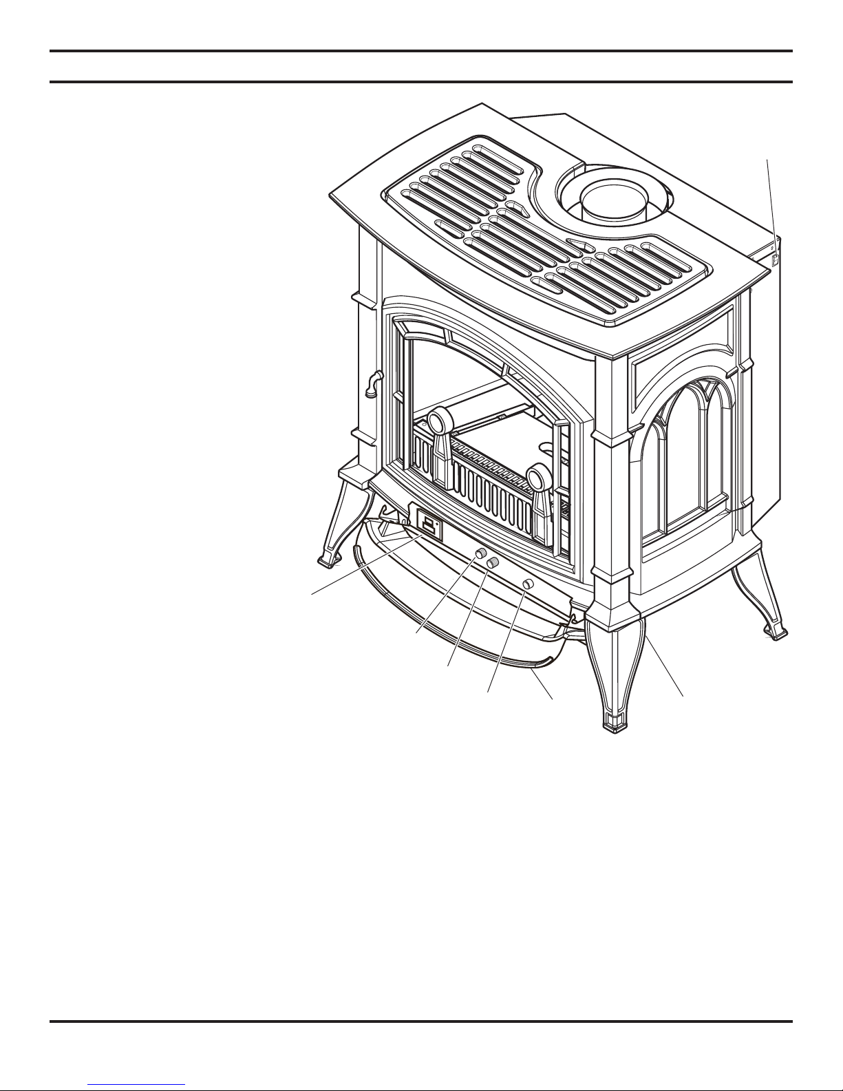
On/Off
Switch
OFF
ON
• For alcove installation see “Clearances,” page 10.
Optional
Remote
Receiver
Hi/Lo
Knob
Pilot
The efficiency rating of this appliance is
a product thermal efficiency rating determined under continuous operating condi-
Optional
Blower
Door
Ignitor Box
Located Under
Right Front Leg
tions and was determined independently
of any installed system.
Thermal Efficiency = up to 80%
Figure 1 - Cast Iron Stove
CODE APPROV AL
Direct Vent type appliances draw all combustion air from outside of the dwelling through the vent pipe.
These appliances have been tested by CSA and found to comply with the established standards for DIRECT VENT GAS
FIREPLACE HEATERS in the USA and Canada as follows:
LISTED VENTED GAS FIREPLACE HEATER
TESTED TO: ANSI Z21.88b-2001/CSA 2.33b-2001 STANDARDS
58D6056 5
PRE-INSTALLATION INFORMATION
INSTALLING ABOVE 2000 FEET
• In the USA, the appliance must be derated 4% for every 1,000 ft above 2,000 ft elevations.
• In Canada, these appliances are certified for altitudes of 0 – 2000 ft, and must be de-rated by 10 percent for installations
between 2000 and 4,500 ft. (derate an additional 4% for every 1,000 ft. above 4,500 ft. elevations).
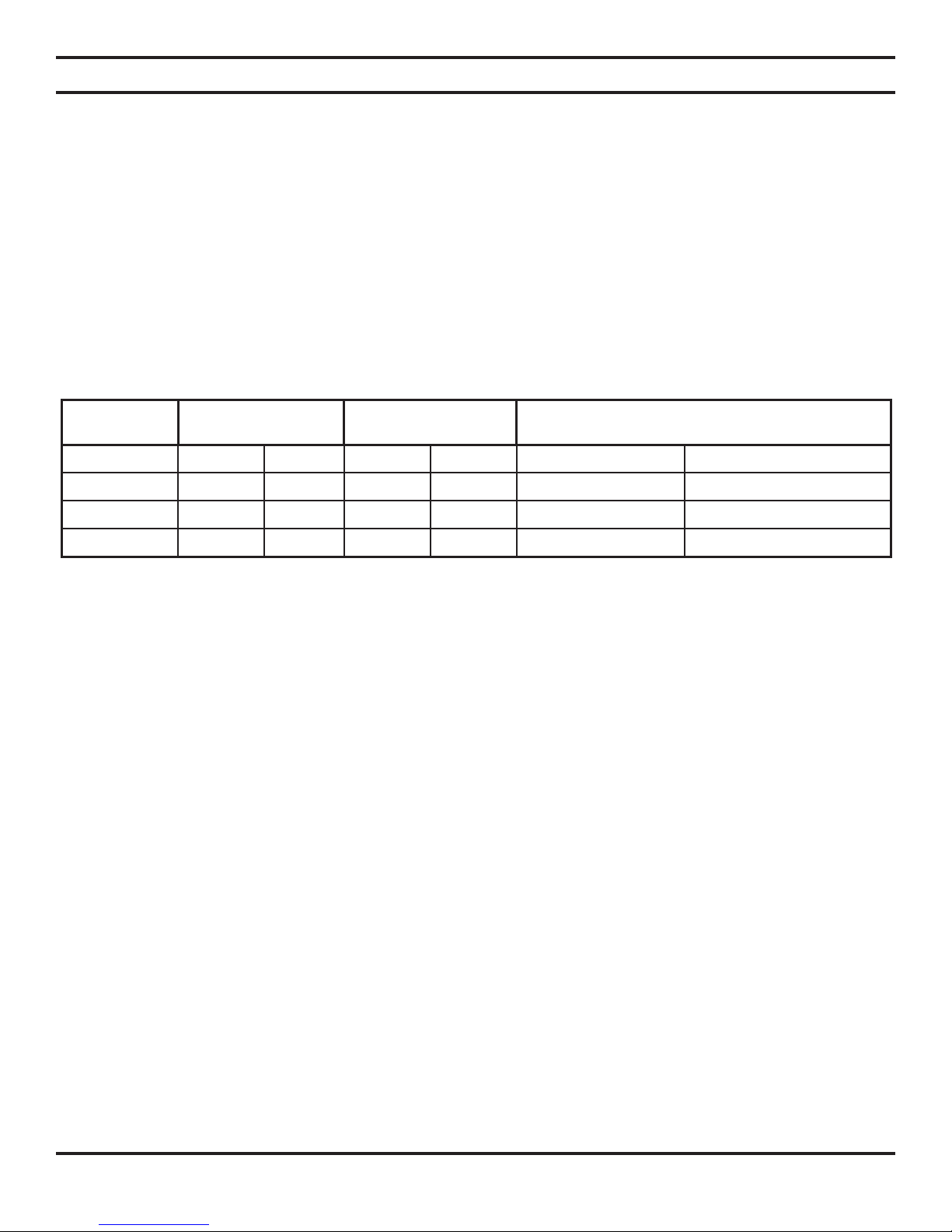
ORIFICE SIZES, PRESSURES AND BTUs
NATURAL GAS PROPANE GAS
Manifold Press: (W.C.) 3.5" Manifold Press: (W.C.) 10"
Maximum Supply Pressure 10.5" Maximum Supply Pressure 13"
Minimum Supply Pressure 4.5" Minimum Supply Pressure 11"
Model
Number CSDV20 CSDV30 CSDV40
Gas Type Natural Propane Natural Propane Natural Propane
Max. BTU/Hr. 18,000 19,000 28,000 28,000 33,000 33,000
Min. BTU/Hr. 12,500 15,000 17,000 21,000 26,000 30,000
Orifi ce size #43 #54 #35 #51 Front #46, Rear #43 Front #57, Rear 1.45mm
Each stove is equipped with a variable output gas control.
6 58D6056
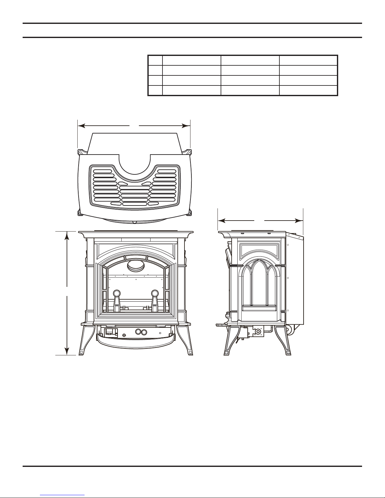
STOVE DIMENSIONS
A
DV20 DV30 DV40
A 20
B 23
C 18
PRE-INSTALLATION INFORMATION
7
/8"26
1
/2"28
3
/4" 21" 22"
1
/2"29
1
/2"30
1
/2"
1
/2"
B
C
Figure 2 - External Stove Dimensions
58D6056 7
PRE-INSTALLATION INFORMATION
STOVE LOCATION
Plan for the installation of your stove. This includes determining where the unit is to be installed, the vent configuration to
be used, framing and finishing details, and whether any optional accessories (i.e. blower, wall switch, or remote control)
are desired. Consult your local building code agency to ensure compliance with local codes, including permits and inspections.
The following factors should be taken into consideration:
• This stove should have sufficient access for its safe operation and maintenance.
• Locate a position where the flue system of the stove can be properly installed without damaging the integrity of the
building. e.g. cutting wall or ceiling joist (example: load-bearing framing members).
• When the appliance is installed directly on carpeting, tile or other combustible material other than wood flooring, you
must set appliance on a metal or wood panel extending the full width and depth of the appliance.
• Check stove and flue system clearance requirements.
• Locate the stove where it can be accessed by a gas supply line.
• Locate the stove in a large and open room that is centrally located in the house. This will optimize heat circulation
and comfort.
• The flow of combustion and ventilation air must not be obstructed.
• Minimum clearances to combustibles, side-wall, ceiling, woodwork, and windows must be maintained. See Figure 4,
page 9.
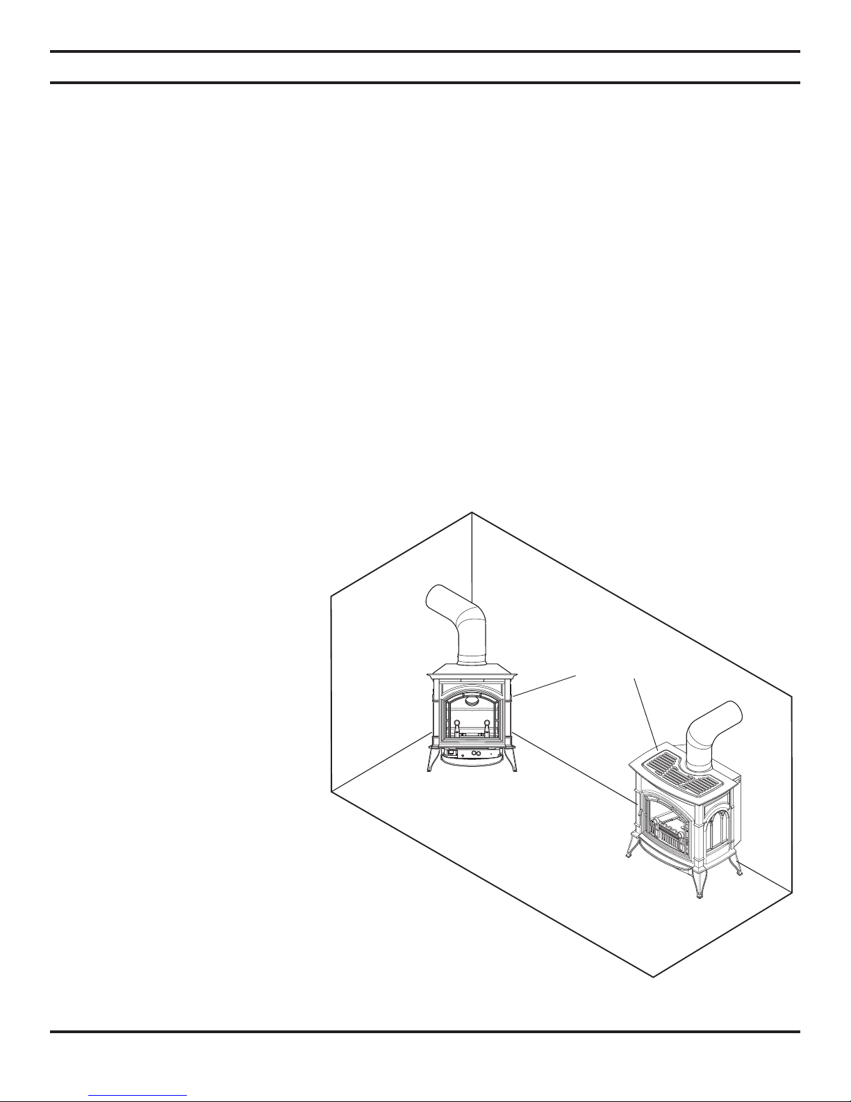
• This stove may be installed along a wall, across a corner, or use an exterior chase. See Figure 3 for suggested locations.
• Location should be out of high traffic areas and away from furniture and
draperies due to heat from appliance.
• Never obstruct the front opening of the
stove.
• Do not install in the vicinity where
gasoline or other flammable liquids may
be stored.
• Vent pipe routing. See Venting section
found in this manual for allowable venting configurations.
• These units can be installed in a bedroom. See National Fuel Gas Code
ANSI Z233.1/NFPA 54 (current edition), the Uniform Mechanical Code
(current edition), and Local Building
Codes for specific installation requirements.
Cast Iron Stove
ON
F
OF
NOTE: If this unit is installed in
a mobile home it must be bolted
securely to the fl oor with leg bolts.
NOTE: Stoves work without any
electrical supply.
8 58D6056
Figure 3 - Example of Typical Installations
(see “Clearances,” page 9)
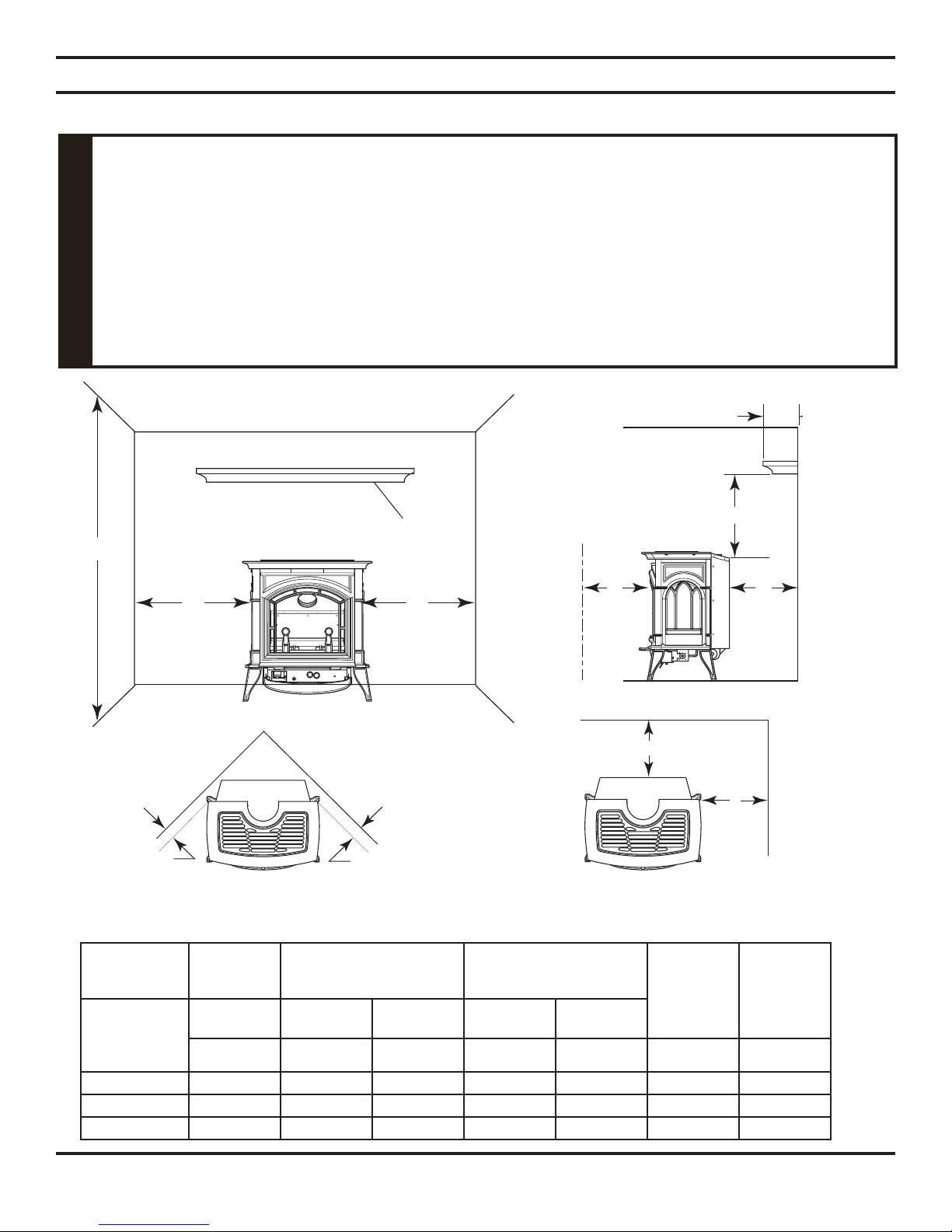
CLEARANCES TO COMBUSTIBLES
The dimensions shown in Figures 4 and 5 are minimum clearances to maintain in
installing this heater. Left and right clearances are determined when facing the front
of the heater.
Follow these instructions carefully to ensure safe installation. Failure to follow
in struc tions exactly can create a fi re hazard.
The appliance cannot be installed on a carpet, tile or other combustible material other
WARNING
than wood fl ooring. If installed on carpet or vinyl fl ooring, the appliance shall be installed
on a metal, wood or noncombustible material panel ex tend ing full width and depth of
the appliance.
CLEARANCES
Side
Wall
Ceiling
Ceiling
B
Side
Wall
Mantel
C
A
E
Minimum
D
Minimum
to Either
Side Wall
36"
in Front
F
Minimum
Side View
Front View
F Minimum
D
Floor
G
G
Minimum
to Either
Side Wall
Floor
Corner Installation
Figure 4 - Minimum Clearance to Walls and Ceiling
Mantel Clearance from
Min. Ceiling
from Floor
Product
DV20 72" 12" 22" 4" 4" 1" ½"
DV30 72" 12" 34" 4" 4" 1" ½"
DV40 72" 12" 34" 4" 4" 1" ½"
58D6056 9
ABCDEFG
Max.
Protrusion Min. Height Right Left
Top of Unit
Wall Installation
Side, Measured from Top
Rear
Measured
from Back
Corner
Measured
From Top
Corners
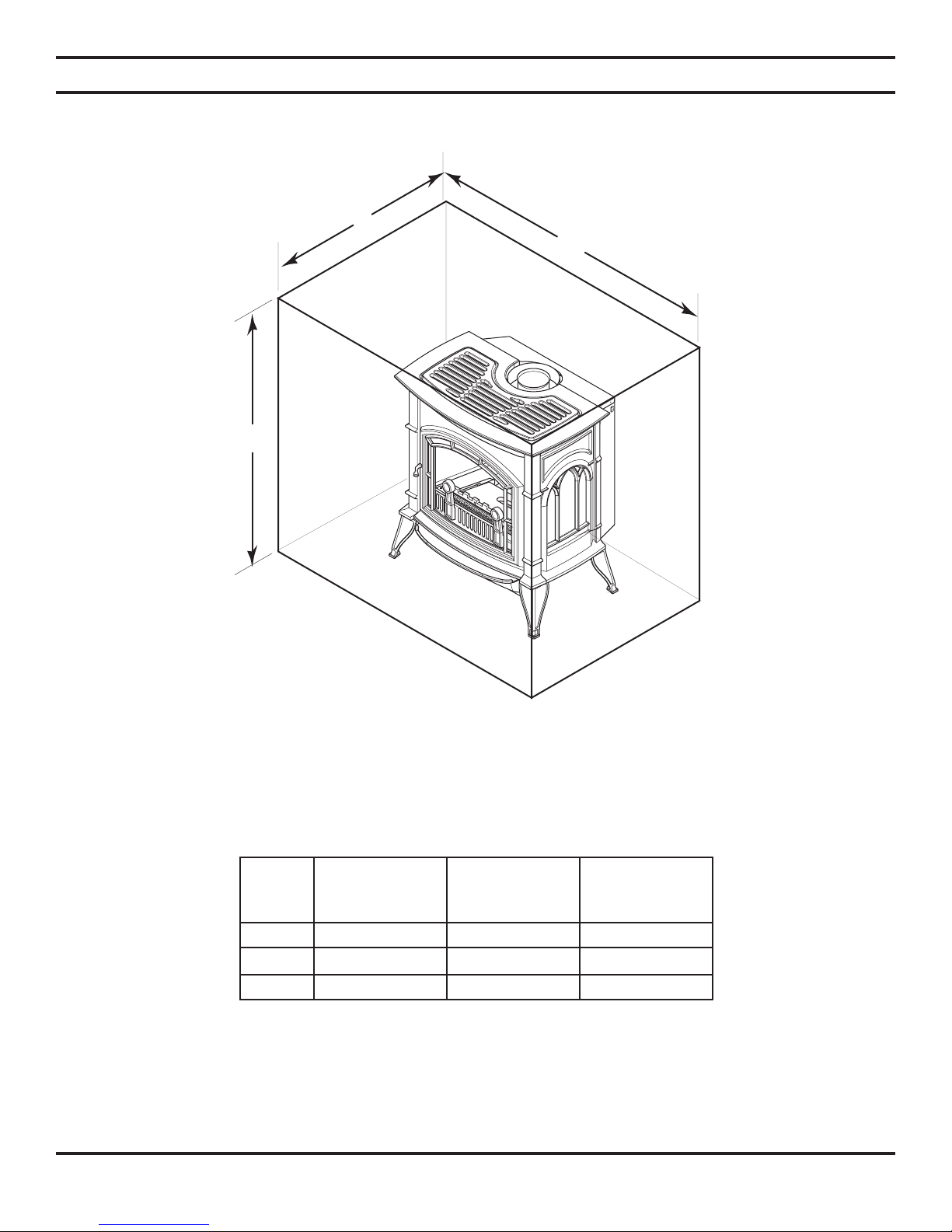
CLEARANCES / HEIGHT REQUIREMENTS
C
A
B
ON
OFF
Figure 5 - Placing Stove in Alcove
Tested Minimum Alcove Dimensions
Height From
Hearth
A
Width
B
Depth
C
DV20 52" 30" 36"
DV30 64" 35" 36"
DV40 64" 35" 36"
Note: Maintain minimum side and back clearances when placing stove in alcove.
10 58D6056
LOGS
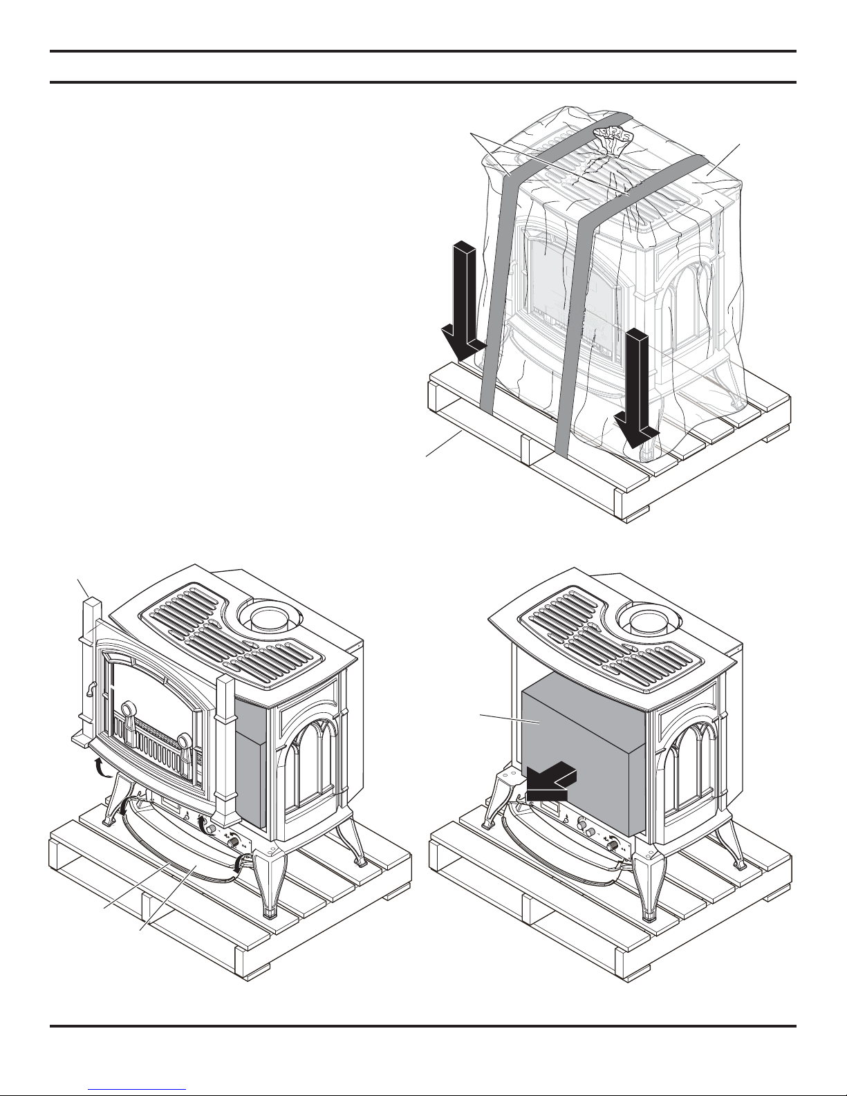
REMOVING UNIT FROM CRATE
1. Remove two (2) straps. See Figure 6.
2. Open plastic bag and slide to bottom of unit. See
Figure 7.
3. Lift up on ash lip and pivot down to open control
door. See Figure 8.
4. Lift up on front. Pivot bottom of front out. Remove
front. See Figure 8.
5. Open and remove glass door.
6. Remove log box from inside of unit.
7. Lift unit off pallet. Lift unit up high enough to clear
upright supports unit is sitting on.
Note: You will need at least two (2) strong
people to lift unit off of pallet.
Pallet
Straps
LOGS
Plastic
Bag
ON
OFF
Hearth
Door
Ash Lip
Control
Door
Figure 6 - Removing Straps and Plastic from Unit
Log
LOGS
REMO
TE
CO
NTR
OL
PILO
T
OFF
Box
LOGS
REMO
TE
CO
NTR
OL
PILOT
OFF
Figure 7 - Opening Control Door and Removing
Hearth Door
58D6056 11
Figure 8 - Removing Log Box
VENT INSTALLATION
Read all instructions completely and thoroughly before attempting installation. Failure
to do so could result in serious injury, property damage or loss of life. Operation of
improperly installed and maintained venting system could result in serious injury,
property damage or loss of life.
WARNING
Failure to follow these instructions will
void the warranty.
NOTICE
INSTALLATION PRECAUTIONS
Consult local building codes before beginning the installation. The installer must make sure to select the proper vent system
for installation. Before installing vent kit, the installer must read this stove manual and vent kit instructions.
Only a qualified installer/service person should install venting system. The installer must follow these safety rules:
• Wear gloves and safety glasses for protection.
• Use extreme caution when using ladders or when on rooftops.
• Be aware of electrical wiring locations in walls and ceilings.
The following actions will void the warranty on your venting system:
• Installation of any damaged venting component.
• Unauthorized modification of the venting system.
• Installation of any component part not manufactured or approved by Lexington Forge.
• Installation other than permitted by these instructions.
This stove must be vented to the outside. The venting system must NEVER be attached
to a chimney serving a separate solid fuel burning appliance. Each gas appliance must
use a separate vent system. Do not use common vent systems.
WARNING
Horizontal sections of this vent system require a minimum clearance of 2" from the top
of the pipe and 1" minimum to the sides and bottom. Vertical sections of this system
require a minimum of 1" clearance to combustible materials on all sides of the pipe. Only
a 1" clearance is required where the vent passes through the nearest vertical wall.
WARNING
12 58D6056
VENT INSTALLATION
INSTALLATION PLANNING
There are two basic types of direct-vent installation:
• Horizontal Termination
• Vertical Termination
It is important to select the proper length of vent pipe for the type of termination you choose. It is also important to note the
wall thickness.
FOR HORIZONTAL TERMINATION
Select the amount of vertical rise desired. The horizontal run
of venting must have
the termination.
You may use up to three 90° elbows in this vent configuration.
See Horizontal Termination Configurations on page 14.
FOR VERTICAL TERMINATION
Measure the distance from the stove flue outlet to the ceiling. Add the ceiling thickness, the vertical rise in an attic or second
story, and allow for sufficient vent height above the roof line. You may use one or two 90° elbows in this vent configuration.
See Vertical Termination Configurations on pages 19 and 20.
NOTE: You may use two 45° elbows in place of a 90° elbow . Y ou must follow rise to run ratios when using
45° elbows. The appliance is approved for use with three 90° elbows maximum or a combination of 90°
and 45° elbows up to a maximum of 270°.
For two-story applications, firestops are required at each floor level. If an offset is needed in the attic, additional pipe and
elbows will be required.
You may use a chase with a vent termination with exposed pipe on the exterior of the house. See Installing Vent System in
a Chase below.
It is very important that the venting system maintain its balance between the combustion air intake and the flue gas exhaust.
Certain limitations apply to vent configurations and must be strictly followed.
INSTALLING A VENT SYSTEM IN AN OUTSIDE CHASE
1
/4" rise for every 12" of run towards
Never run the vent pipe level or
downward. This may cause excessive
temperatures which could cause a
fi re.
WARNING
A chase is a vertical boxlike structure built to enclose venting that runs along the outside of a building. A chase is required
for such venting.
Treatment of fi restops and construction of the chase may vary from building type to
building type. These instructions are not substitutes for the requirements of local
building codes. You must follow all local building codes.
NOTICE
NOTE: When installing in a chase, you should insulate the chase as you would the outside walls of
your home. This is especially important in cold climates. Minimum clearance between vent pipes and
combustible materials such as insulation is 1".
58D6056 13
VENT INSTALLATION
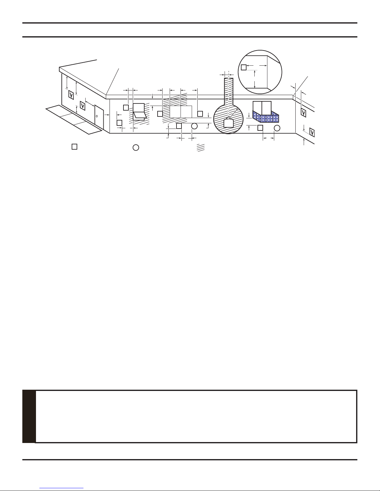
Inside Corner Detail FOR HORIZONTAL TERMINATION
G
V
H
D
E
B
L
Vent Terminal Air Supply Inlet Area Where Terminals Not Permitted
V
C
Fixed
V
Closed
F
Operable
V
B
A
BB
B
Opera-
ble
V
A
V
Fixed
Closed
J
V
A
B
Figure 9 - Horizontal Vent Termination Location
MINIMUM DISTANCES
A = Clearance above the grade, a veranda, porch, deck, or balcony [*12" (305mm) minimum].
B = Clearance to window or door that may be opened [*12" (305mm) minimum].
C = Clearance to permanently closed window [*minimum 12" (305mm) recommended to prevent condensation on
window]
D
= Vertical clearance to ventilated soffit located above the terminal within a horizontal distance of two (2) feet (610mm)
from the centerline of the terminal [18" (457mm) minimum].
E = Clearance to unventilated soffits [12" (305mm) minimum]. Clearance to vinyl soffit [30" (762mm)].
F = Clearance to an outside corner. See page 12.
G = Clearance to an inside corner. See page 12.
H = *Not to be installed above a gas meter/regulator assembly within three (3) feet (914mm) horizontally from the centerline
of the regulator.
I = Clearance to service regulator vent outlet [*3' (914mm) minimum].
J = Clearance to non-mechanical air supply inlet to building or the combustion air inlet to any other appliance [*12"
(305mm)minimum].
K = Clearance to a mechanical air supply inlet [*6' (1829mm) minimum].
L = Clearance above a paved sidewalk or paved driveway located on public property [**7' (2133mm) minimum].
M = Clearance under veranda, porch, deck, or balcony [*12" (305mm) minimum
* As specified in CAN/CGA B149 Installation Codes. Note: Local codes or regulations may require different
clearances.
** A vent must not terminate directly above a sidewalk or paved driveway, which is located between two single-family
dwellings and serves both dwellings.
*** Only permitted if veranda, porch, deck, or balcony is fully open on a minimum of two sides beneath the floor.
A
G
I
M
V
***
A
K
].
A
Always maintain minimum clearances around vent systems. The minimum clearances
to combustibles for horizontal vent pipe are 2" at the top and 1" at the sides and bottom
of the vent system. For wall fi restops, a 1" minimum clearance all around the pipe must
be maintained. Do not pack the open air spaces with insulation or other materials. This
could cause high temperatures and may present a fi re hazard.
WARNING
14 58D6056
m
TERMINATION CLEARANCES FOR BUILDINGS WITH COMBUSTIBLE
AND NONCOMBUSTIBLE EXTERIORS
VENT INSTALLATION
G G=6" (152mm)
V
Inside Corner
V
F
Outside Corner
F=6" (152mm)
H
G
V
Combustible &
G = Combustible 24"(610mm)
Noncombustible 18"(457mm)
Balcony with No Side Wall Balcony with Perpendicular
Noncombustible
H = 24" (610mm)
J = 20" (508mm)
V
J
Side Wall
Figure 10 - Allowable Venting Chart
D
C
C
V
E
C = Maximum depth of 48" (1219mm)
for alcove location
D = Minimum width for back wall of
alcove location
Combustible - 38" (965mm)
Noncombustible - 24" (610mm)
E = Clearance from corner in alcove
location
Combustible - 6" (152mm)
Noncombustible - 2" (51mm)
Alcove Location
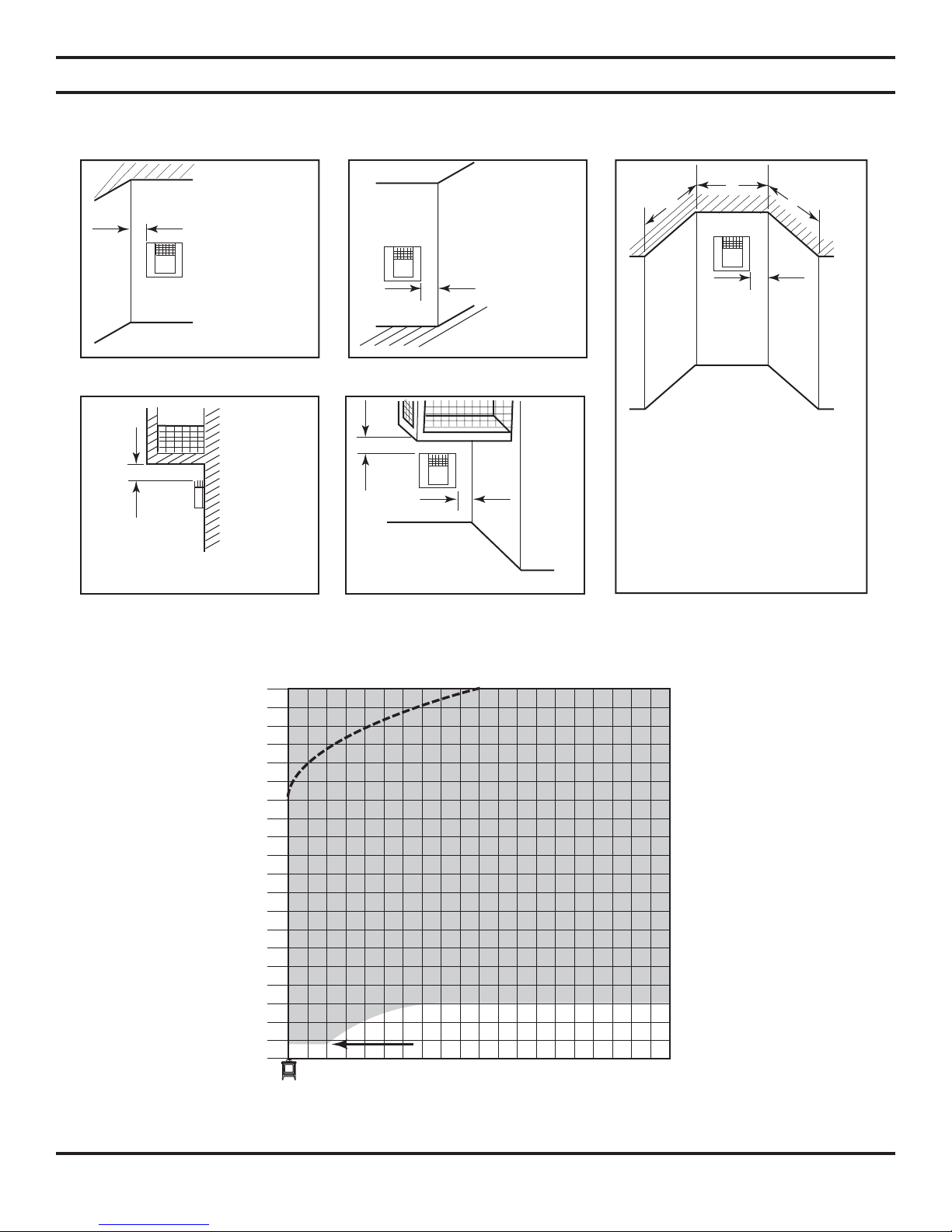
VERTICAL HEIGHT 40' MAX (12.2m)
Actual Stove Height
DV20 = 23
DV30 = 28
DV40 = 30
1
/2"
3
/2"
1
/2"
40
38
36
34
32
30
28
26
24
22
20
18
16
14
12
10
(MEASURED FROM STOVE TOP)
8
6
4
2
0
Use Restrictor
Disk Above
Dotted
Line
NOTE: Any vent configurations within
the shaded areas are acceptable.
Minimum Height from Stove Top 18"
1234567891011 121314151617181920
HORIZONTAL RUN 20' MAX (6.1m)
Figure 11 - Acceptable Vent Confi gurations
Minimum Height fro
Stove Top
DV20 = 18"
DV30 = 30"
DV40 = 30"
58D6056 15
 Loading...