

Lexington Forge ASHTON AI31DVC Installation And Operating Instructions Manual
MODEL: ASHTON AI31DVC
LEXINGTON FORGE
DIRECT VENT GAS INSERT
INSTALLATION AND OPERATING INSTRUCTIONS
WARNINGS
IF THE INFORMATION IN THESE INSTRUCTIONS ARE
NOT FOLLOWED EXACTLY, A FIRE OR EXPLOSION
MAY RESULT CAUSING PROPERTY DAMAGE,
PERSONAL INJURY OR LOSS OF LIFE.
– Do not store or use gasoline or other flammable
vapors and liquids in the vicinity of this or any
other appliance.
– WHAT TO DO IF YOU SMELL GAS
• Do not try to light
any appliance.
• Do not touch
any electrical switch; do not use
any phone in your building.
• Immediately call your gas supplier from a
neighbor's phone. Follow the gas supplier's
instructions.
• If you cannot reach your gas supplier, call the
fire department.
– Installation and service must be performed
by a qualified installer, service agency or the
gas supplier.
WARNING: Improper installation, adjustment,
alteration, services or maintenance can cause injury or
property damage. Refer to this manual. For assistance
or additional information consult a qualified installer,
service agency or the gas supplier.
This appliance is only for use with the type of gas
indicated on the rating plate. This appliance is
not convertible for use with other gases, unless a
certified kit is used.
This appliance may be installed in an aftermarket*,
permanently located, manufactured home, where not
prohibited by local codes.
*Aftermarket: Completion of sale, not for purpose of resale, from
the manufacturer.
DUE TO HIGH TEMPERATURES, THE
APPL I ANCE SHOULD BE LOCATED
OUT OF TRAFFIC AND AWAY FROM
FURNITURE AND DRAPERIES.
CHILDREN AND ADULTS SHOULD BE
ALERTED TO THE HAZARDS OF HIGH
SURFACE TEMPERATURE AND SHOULD
STAY AWAY TO AVO I D B U R NS OR
CLOTHING IGNITION.
Y O U N G C H I L D R EN S H O UL D B E
SUPERVISED WHEN THEY ARE IN THE
SAME ROOM AS THE APPLIANCE.
CLOTHING OR OTHER FLAMMABLE
MATERIAL SHOULD NOT BE PLACED
ON OR NEAR THE APPLIANCE.
KEEP THE ROOM AREA CLEAR AND
FREE FROM COMBUSTIBLE MATERIALS,
GASOLINE, AND OTHER FLAMMABLE
VAPORS AND LIQUIDS.
READ BEFORE INSTALLING. SAVE THESE INSTRUCTIONS

2 48D0586
CONTENTS
Important Safety Information .......................... 3
Product Features .............................................. 5
Code Approval .................................................. 5
Pre-Installation Information
Installing Above 2000 Feet ............................ 6
Orifice Sizes, Pressures and BTUs ............... 6
Installation Planning...................................... 6
Fireplace and Insert Dimensions .................... 7
General Installation Information ..................... 8
Clearances .................................................... 8
Installation ......................................................... 9
Insert Clearances .......................................... 9
Mantel Clearances ........................................ 9
Hearth Requirements .................................... 9
Insert Placement ......................................... 10
Zero-Clearance (Metal) Fireplace
Requirements ...............................................11
Vent Installation .............................................. 12
Installation Precautions ............................... 12
Vent Requirements ..................................... 13
Altitude Considerations ............................... 13
Vent Configurations ..................................... 14
Manifold Installation .................................... 15
Insert Installation
Check Gas Type .......................................... 18
Installing Gas Piping to Insert/Burner System
Location ...................................................... 18
Checking Gas Pressure ................................. 20
Electrical Installation ..................................... 21
Electrical Wiring .......................................... 21
Remote Wall Switch .................................... 21
Log Placement ................................................ 22
Surround and Trim Installation .....................
26
Installing Facing .......................................... 26
Installing On/Off Switch... ........................... 26
Door Installation ............................................. 27
Filigree Installation ......................................... 28
Operating Instructions ................................... 29
What To Do If You Smell Gas ...................... 29
Lighting Pilot for the First Time ...................
29
Lighting Pilot ............................................... 30
Lighting Burner ............................................ 31
To Turn Off Gas ........................................... 31
Adjusting Blower Speed .............................. 31
Cleaning Maintenance.................................... 32
Venting System ........................................... 32
Cleaning Glass ............................................ 32
Pilot and Burner Flames ............................. 32
Firebox Cleaning ......................................... 32
Air Shutter Adjustment (Natural Gas Only) ..
33
Glass Replacement ........................................ 34
Maintenance .................................................... 35
Maintaining Your Heater’s Appearance ....... 35
Yearly Service Procedure ............................ 35
Blower.............................................................. 37
Replacement Parts ......................................... 38
Troubleshooting .............................................
40
Warranty ...........................................Back Cover
CONGRATULATIONS!
You have purchased a state-of-the-art gas appliance featuring the Lex-Fire Burn System
available exclusively on Lexington Forge gas appliances.
The Lex-Fire Burn System sets a new standard for flame appearance through innovative log
design, burner technology and ember placement. Each element affecting combustion and
flame appearance was carefully scrutinized and strategically balanced during the design
process to provide a product that was truly
“BORN TO BURN.”

48D0586 3
4. Never install the insert
• in a recreational vehicle
• where curtains, furniture, clothing, or other flammable
objects are less than 36" from the front, top, or sides
of the insert
• in high traffic areas
• in windy or drafty areas
5. This insert reaches high temperatures. Keep children and
adults away from hot surfaces to avoid burns or clothing
ignition. Insert will remain hot for a time after shutdown.
Allow surfaces to cool before touching.
6. Carefully supervise young children when they are in the
room with insert.
7. Do not modify this insert under any circumstances. Any
parts removed for servicing must be replaced prior to
operating insert.
8. Turn insert off and let cool before servicing, installing, or
repairing. Only a qualified service person should install,
service, or repair the insert. Have burner system inspected
annually by a qualified service person.
9. You must keep control compartments, burners, and cir
culating air passages clean. More frequent cleaning may
be needed due to excessive lint and dust from carpeting,
bedding material, pet hair, etc. Turn off the gas valve and
pilot light before cleaning insert.
10. Have venting system inspected annually by a qualified
service person. If needed, have venting system cleaned
or repaired. See Cleaning and Maintenance, page 30.
11. Keep the area around your insert clear of combustible
materials, gasoline, and other flammable vapor and liq
uids. Do not run insert where these are used or stored.
Do not place items such as clothing or decorations on or
around insert.
INSTALLER
Please leave these instructions with the appliance.
OWNER
Please retain these instructions for future reference
.
IMPORTANT SAFETY INFORMATION
This insert is a vented product. This insert must be properly
installed by a qualified service person. The glass door must be
properly seated and sealed. If this unit is not properly installed
by a qualified service person with glass door properly seated
and sealed, combustion leakage can occur.
CARBON MONOXIDE POISONING:
Early signs of
carbon monoxide poisoning are similar to the flu with headaches, dizziness and/or nausea. If you have these signs, the
insert may not have been installed properly. Get fresh air at
once! Have the insert inspected and serviced by a qualified
service person. Some people are more affected by carbon
monoxide than others. These include pregnant women, people
with heart or lung disease or anemia, those under the influence
of alcohol, and those at high altitudes.
Propane/LP gas and natural gas are both odorless. An odormaking agent is added to each of these gases. The odor helps
you detect a gas leak. However, the odor added to these gases
can fade. Gas may be present even though no odor exists.
Make certain you read and understand all warnings. Keep this
manual for reference. It is your guide to the safe and proper
operation of this insert.
1. This appliance is only for use with the type of gas indi
cated on the rating plate. This appliance is not convertible
for use with other gases unless a certified kit is used.
2. For propane/LP insert, do not place propane/LP supply
tank(s) inside any structure. Locate propane/LP supply
tank(s) outdoors. To prevent performance problems, do not
use propane/LP fuel tank of less than 100 lbs. capacity.
3. If you smell gas
• shut off gas supply.
• do not try to light any appliance.
• do not touch any electrical switch; do not use any
phone in your building .
• immediately call your gas supplier from a neighborʼs
phone. Follow the gas supplierʼs instructions.
Continued on page 4
• Read this owner’s manual carefully and completely before trying to assemble, operate,
or service this insert.
• Any change to this insert or its controls can be dangerous.
• Improper installation or use of this insert can cause serious injury or death from fire,
burns, explosions, electrical shock and carbon monoxide poisoning.
WARNING

4 48D0586
IMPORTANT SAFETY INFORMATION
Continued from page 3
12. Do not use this insert to cook food or burn paper or other
objects.
13. Never place anything on top of insert.
14. Do not use any solid fuels (wood, coal, paper, cardboard,
etc.) in this insert. Use only the gas type indicated on
rating plate.
15. This appliance, when installed, must be electrically
grounded in accordance with local codes or in the
absence of local codes, with the National Electrical
Code, ANSI/NFPA 70, or the Canadian Electrical Code,
CSA C22.1.
16. Do not obstruct the flow of combustion and ventilation
air in any way. Provide adequate clearances around
air openings into the combustion chamber along with
adequate accessibility clearance for servicing and proper
operation.
17. Do not use insert if any part has been exposed to or
under water. Immediately call a qualified service person
to arrange for replacement of the unit.
18. Do not operate insert if any log is broken.
19. Do not operate the insert with glass door removed,
cracked, or broken.
20. For Massachusetts Residents Only: This product
must be installed by a licensed plumber or gas fitter when
installed within the Commonwealth of Massachusetts.
Flexline installation must not exceed 36".
48D0586 5
PRODUCT FEATURES AND CODE APPROVAL
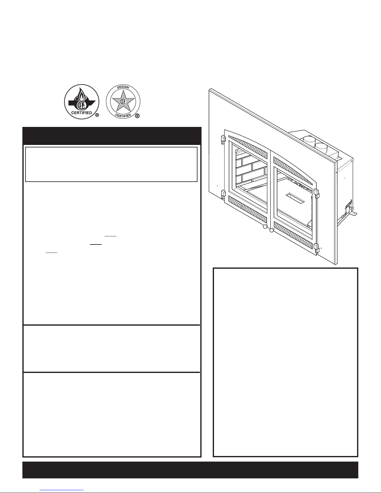
Figure 1 - AI31DV Insert
• This appliance has been
certified for use with either
natural or propane gas. See
appropriate data plates.
• This appliance is not for use
with solid fuels.
• The appliance is approved
for bedroom or bedsitting
room installations.
• The ap p l i a n c e must be
inst a l led in accord a n ce
with local codes if any. If
none exist use the current
ins talla tion cod e. ANSI
Z22 3.1/NF PA 54 in the
USA, CAN/CGA B149 in
Canada.
• This appliance is mobile
home approved.
• The appliance must be prop
erly connected to a venting
system.
PRODUCT SPECIFICATIONS
The efficiency rating of this appliance is a product thermal efficiency rating determined under continuous operating conditions and was determined independently of any installed system.
Thermal Efficiency = up to 80%
CODE APPROVAL
These appliances have been tested by CSA and found to comply with the established standards for VENTED GAS FIREPLACE HEATERS in the USA and Canada as follows:
LISTED VENTED GAS FIREPLACE HEATER
TESTED TO: ANSI Z21.88-2002/CSA 2.33-2002 STANDARDS
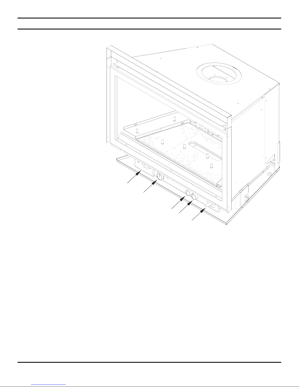
Remote Receiver
Gas shut-off Valve
Hi/Lo Knob
Off/Pilot/On Knob
Blower
Optional
6 48D0586
PRE-INSTALLATION INFORMATION
INSTALLING ABOVE 2000 FEET
• In the USA, the appliance must be derated 4% for every 1,000 ft above 2,000 ft elevations.
• In Canada, these appliances are certified for altitudes of 0 – 2000 ft, and must be de-rated by 10 percent for installations
between 2000 and 4,500 ft. (derate an additional 4% for every 1,000 ft. above 4,500 ft. elevations).
The ASHTON AI31 is equipped with a variable output gas control.
ORIFICE SIZES, PRESSURES AND BTUs
NATURAL GAS PROPANE GAS
Manifold Press: (W.C.) 3.5" Manifold Press: (W.C.) 10"
Maximum Supply Pressure 10.5" Maximum Supply Pressure 13"
Minimum Supply Pressure 4.5" Minimum Supply Pressure 11"
NOTE: Ashton AI31 model insert works without any electrical supply.
Blower must have electricity.
INSTALLATION PLANNING
Plan for the installation of your insert. This includes determining the size of fireplace in which unit is to be installed, length of
venting to be used, and finishing details, and whether any optional accessories (i.e. wall switch, or remote control) are desired.
Consult your local building code agency to ensure compliance with local codes, including permits and inspections.
Model Number AI31
NATURAL PROPANE
Max. Btu/hr Input 33,000 31,000
Min. Btu/hr Input 23,000 23,000
Orifice sizes (as shipped) #35 #51
48D0586 7
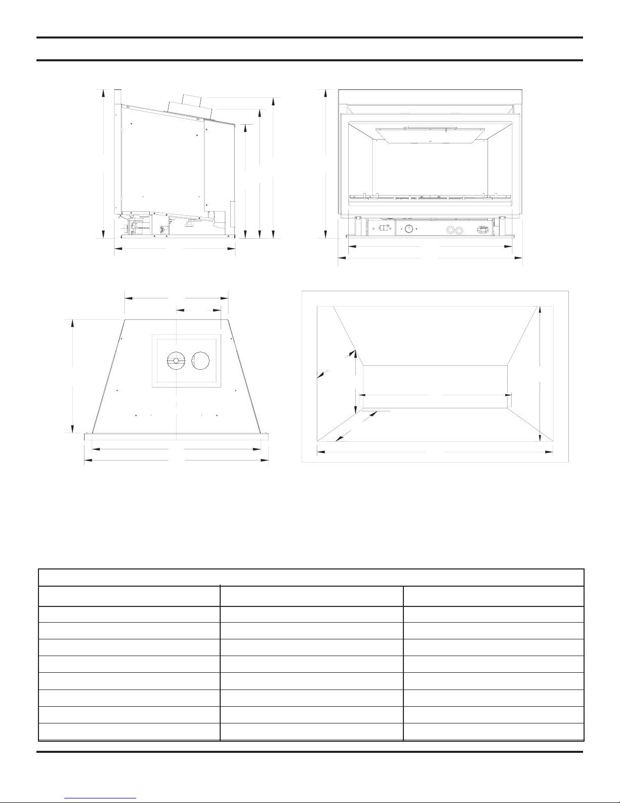
Figure 2 - External Insert Dimensions
FIREPLACE AND INSERT DIMENSIONS
L - Fireplace opening height O - Firebox width at insert depth (N)
M - Fireplace opening width P - Firebox depth at insert back height (Q)
N - Depth of insert Q - Insert back height
AI31
FIREPLACE FIREPLACE MINIMUM OPENING
A 23
5
/8" 601mm D 161/2" 418mm
B 29
1
/4" 743mm E 7" 179mm
C 26" 660mm F 26
3
/4" 680mm
G 18
1
/8" 459mm
H 18
1
/8" 460mm
I 20
1
/2" 521mm
J 22
3
/8" 567mm
K 19
1
/4" 488mm
L 21
1
/2" 546mm
M 26
7
/8" 683mm
N 18
1
/4" 464mm
O 16
5
/8" 422mm
P 14
1
/2" 368mm
Q 20
5
/8" 524mm
A
B
C
Front
Q
P
N
E
D
M
B
F
Side
Top Fireplace Opening
L
O
J
I
H
A
K
G

8 48D0586
GENERAL INSTALLATION INFORMATION
The following factors should be taken into consideration:
• This insert should have sufficient access for its safe operation and maintenance.
• The flow of combustion and ventilation air must not be obstructed.
• Minimum clearances to combustibles, such as mantels,
must be maintained. See Figures 3 and 4, pages 10 and 11.
• Never obstruct the front opening of the insert.
• Do
not install in the vicinity where gasoline or other flammable liquids may be stored.
• These units can be installed in a bedroom. See National Fuel Gas Code ANSI Z233.1/NFPA 54 (current edition), the
Uniform Mechanical Code (current edition), and Local Building Codes for specific installation requirements.
IMPORTANT: Your direct vent insert was designed to be installed in an existing wood burning fireplace.
The fireplace location and clearances are subject to local building codes.
INSERT APPLICATIONS
Before installing the gas fireplace insert, consider the functioning needs of the fireplace. Confirm the size of the fireplace
cavity, the design of the chimney, and the availablility of the gas supply and electricity for the insert fan.
IMPORTANT: Your direct vent insert can be only vented vertically with a minimum height of 10 feet.
When the unit is installed into a woodburning fireplace, the minimum distance the mantel can be placed above the fireplace is
governed by local building codes applicable to woodburning fireplaces. Consult local authorities having jurisdiction for these
clearances. The underside of the mantel will become warm. Use only finishes which are heat resistant and do not discolor.
The dimensions shown in Figures 3 and 4, pages 9 and 10, are minimum clearances to
maintain when installing this heater. Follow these instructions carefully to ensure safe
installation. Failure to follow instructions exactly can create a fire hazard.
WARNING
CLEARANCES
MINIMUM FIREPLACE SIZE/CLEARANCES TO COMBUSTIBLES
Maintain the following minimum clearances for service and maintenance. See pages 9 and 10.
48D0586 9
INSTALLATION
INSERT CLEARANCES
No combustibles (ie: drapes, doors) may be within, or swing within, 36" of the front of the insert.
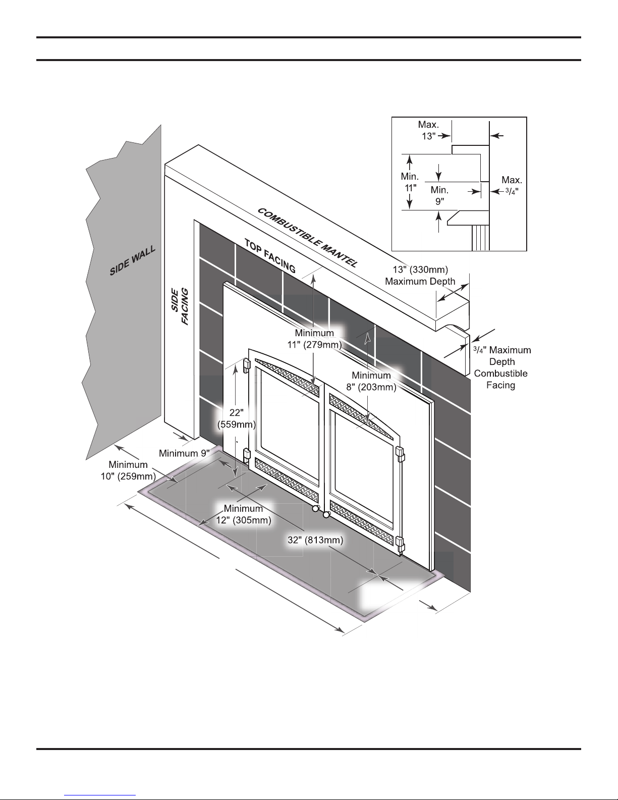
MANTEL CLEARANCES
NOTE: The combustible area above the facing must not protrude more than 3/4" from the facing. If it
does, it is considered a mantel and must meet the mantel requirements shown above.
HEARTH REQUIREMENTS
The insert must be installed on a non-combustible hearth extending a minimum of 12" from the fireplace opening (local
codes may require a larger hearth). The hearth must also extend to both sides of the face (see the table above for the exact
width of the face).
Figure 3 - Mantel Clearances
10 48D0586
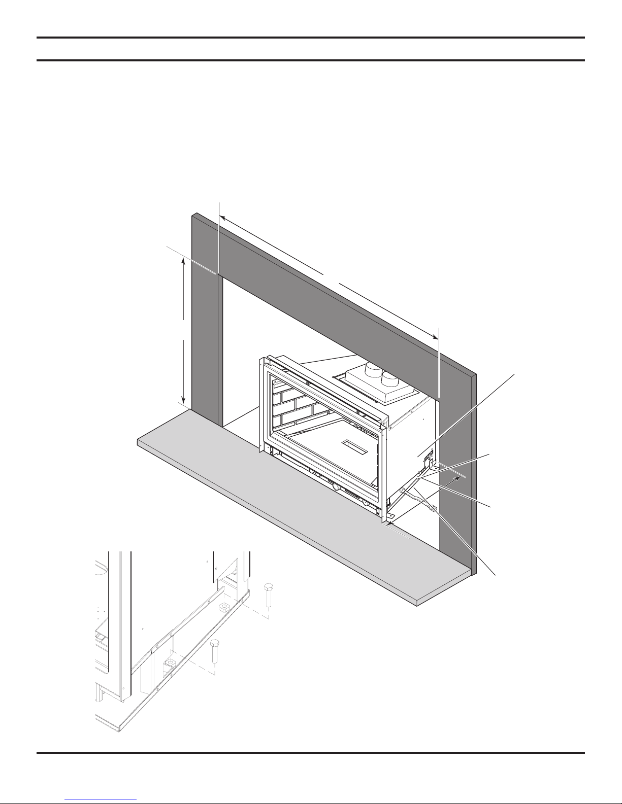
INSTALLATION
INSERT PLACEMENT
• Insert must be placed within a code-conforming masonry fireplace or a tested and listed zero-clearance (metal) fireplace.
Repair any fireplace damage prior to installation.
• Because the insert uses a circulation blower, clean the fireplace, smoke shelf, and chimney before installing. Interior
surface of the fireplace may be painted with latex paint to further eliminate dust.
• This heater may be placed in a bedroom. Please be aware of the large amount of heat this appliance produces when
determining a location.
(546mm)
The gas line
should be installed
prior to insert
placement.
Run the power
cord either side of
the insert along
the face.
Use the leveling
bolts for fireplaces
with recessed floors
The insert protrudes
181/8" (460mm)
into the fireplace.
Minimum 267/8" (683mm)
For tight fits you may remove the manifold.
See “Removing the Mainfold,” page 15
Figure 4 - Insert Placement
Minimum 21
1
/2"
NOTE: Install leveling bolts
on fireplaces with recessed
floors as shown. Install bolts
on left side too.
48D0586 11
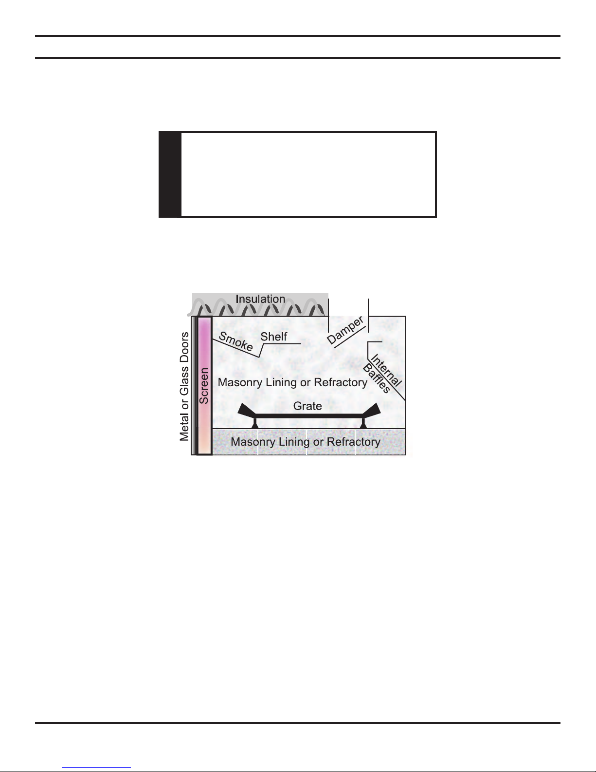
ZERO-CLEARANCE (METAL) FIREPLACE REQUIREMENTS
• The damper and grate must be removed to install venting cap.
• The smoke shelf internal baffles, screen, refractory, and metal or glass doors may be removed (if applicable).
Do not cut any sheet metal parts of the
fireplace in which this gas fireplace
insert is installed. THIS IS STRICTLY
PROHIBITED!
WARNING
• Do not remove or alter the insulation or any structured rigid frame members (metal sides, floor, door frame, face of the
fireplace, etc.).
INSTALLATION
Figure 5 - Metal Fireplace Zero-Clearance Requirements
IMPORTANT:Please review the following carefully.
It is normal for inserts fabricated of steel to give off some expansion and/or contraction noises during the start up or cool
down cycle. Similar noises are found with your furnace heat exchanger or car engine.
It is not unusual for your Lexington Forge insert to give off some odor the first time it is burned. This is due to the curing of
the paint and any undetected oil from the manufacturing process.
Please ensure that your room is well-ventilated. OPEN ALL WINDOWS DURING INITIAL BURN OFF/
CURING PHASE.
Burn your insert for a least six (6) hours on “HIGH” the first time you use it. Place fan in the “OFF” position during
this time.
12 48D0586
VENT INSTALLATION
Read all instructions completely and thoroughly before attempting installation. Failure
to do so could result in serious injury, property damage or loss of life. Operation of
improperly installed and maintained venting systems could result in serious injury,
property damage or loss of life.
WARNING
Failure to follow these instructions will
void the warranty.
NOTICE
INSTALLATION PRECAUTIONS
Consult local building codes before beginning the installation. The installer must make sure to select the proper vent system
for installation. Before installing vent kit, the installer must read this insert manual and vent kit instructions.
Only a qualified installer/service person should install venting system. The installer must follow these safety rules:
• Wear gloves and safety glasses for protection.
• Use extreme caution when using ladders or when on rooftops.
• Be aware of electrical wiring locations in walls and ceilings.
The following actions will void the warranty on your venting system:
• Installation of any damaged venting component.
• Unauthorized modification of the venting system.
• Installation of any component part not manufactured or approved by Lexington Forge.
• Installation other than permitted by these instructions.
This insert must be vented to the outside. The venting system must NEVER be attached
to a chimney serving a separate solid fuel burning appliance. Each gas appliance must
use a separate vent system. Do not use common vent systems.
WARNING
48D0586 13
VENT INSTALLATION
VENT REQUIREMENTS
• Make sure the exhaust pipe on heater connects to
exhaust portion of cap. Attach flex liners. See
Figure 7.
(Mark one vent pipe at both ends to identify it as the
exhaust during installation.)
• Do not crimp or rupture liner when bending it into
chimney offsets.
WARNING
• The exhaust vent must reline the entire length of chimney and terminate
above chimney top.
• Vent must meet all vent manufacturerʼs requirements when installed.
• Make sure you have the following before installing unit:
• 3" UL 1777 Listed gas liners for air inlet and exhaust
• Vertical termination kit (AI31TK33A)
ALTITUDE CONSIDERATIONS
This heater has been tested at altitudes ranging from sea level to 4,500 feet
(USA), 0-2000 feet (Canada). In this testing, heater with standard orifice
burns correctly with just an air shutter adjustment. If you need to resize
orifice for use at high altitude, contact your Lexington Forge dealer.
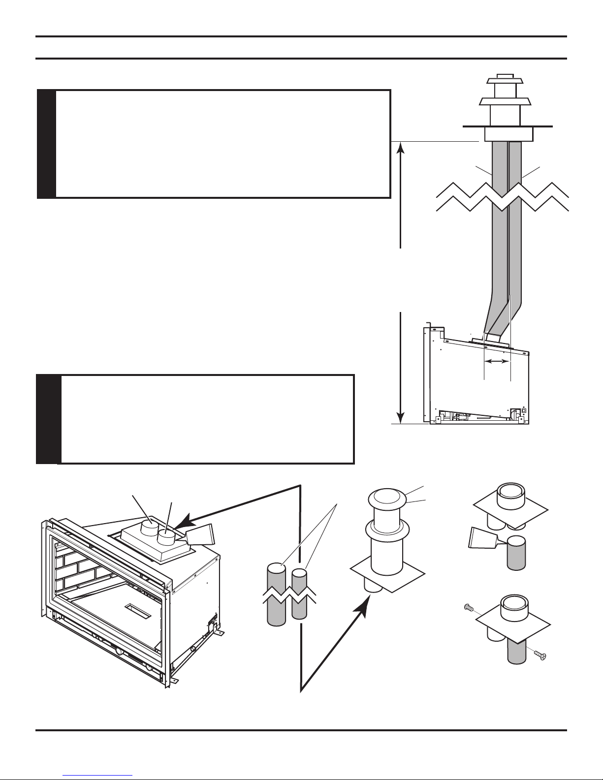
Figure 6 - Venting Unit
Exhaust Inlet
Maximum Height
40' (12.9 M)
Minimum Height
10' (3 M)
Maximum
1'
(305mm)
Offset
Figure 7 - Connecting Exhaust Pipe to Heater
Exhaust
Inlet
3" UL 1777
Gas Liner
Termination Kit
(AI31TK33A)
Apply high-temperature silicone
to lines on both ends and
secure with two (2) screws.
Failure to adjust air shutter properly may lead to
improper combustion which can create a safety
hazard. Consult your dealer or installer if you
suspect an improperly adjusted air shutter
WARNING
14 48D0586
VENT INSTALLATION
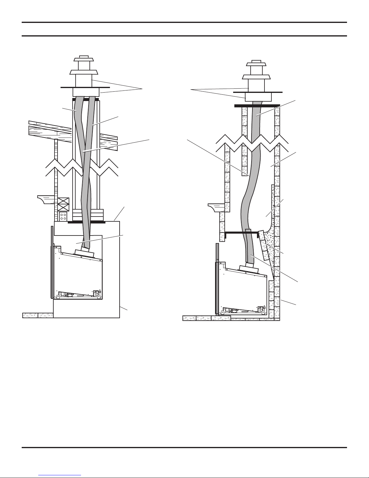
VENT CONFIGURATIONS
Recommended block-off
plate (non-combustible
metal). Prevents
odors from chimney
entering room.
Suggestion:
Paint fireplace cavity
with latex paint to
eliminate possibility of
odors from fireplace
circulating into the room.
Z.C. (metal) firebox
Exhaust
Any cracks or
damage inside
chimney must
be repaired.
The block-off plate
(AI31AK33A) must
seal intake to the
chimney space so
that air is drawn
down chimney for
combustion air.
Block-off Plate AI31AK33A)
(non-combustible
materials)
Inlet
Masonry
Fireplace
NOTE: You may use either reline configuration with a masonry or zero-clearance fireplace.
Exhaust
Inlet
Termination Kit
(part # AI31TK33A)
3" (100mm)
Exhaust
UL 1777 Gas Liner
3" (75mm) Inlet
Figure 8 - Inlet and Exhaust Reline Figure 9 - Exhaust Only Reline
 Loading...