

Page 1
Quick operation instruction of the LX-HS03 system basic configure
Open the main, connect the standby power in the main and switch on power by AC power adapter. Here the
main’s POWER,AWAY LED light and the numeric LED display counting down time 9,8,7…1, and after 1 DI sound
you can operate the main.
1.Outer device accession operation
1.1 remote controller’s original accession
The system can access 4 remote controllers for operation. Press* key and then input operation password (when
out factory, the password is 0000), press SET to enter the setting mode. Press the function channel key”4”, and then
input the first remote controller channel---- “1” and then press # key, within 60sec press the remote controller’s key,
the main will give “ DI” sound, which indicate the main have accept it. Repeat pressing CE key until “DIDI” sound is
heard to exit the setting mode. So the accession of the first remote controller has finished. By the means same as
above, you only need input remote controller channel “ 2”/”3”/”4” , the second/third/ fourth remote controller can be
accessed. At last you can repeat pressing CE key until “DIDI” sound is heard to exit the setting mode. And then the
remote controller can control the main.
1.2 medical for help accession
1.2.1 the remote controller “+” is designed to medical for help. It’s function channel is “ 2” same as other outer
wireless device;
1.2.2 press * key, input operation password 0000, and then press SET key to enter the setting mode. Press function
channel key”2” and then select a numeral as the one that the main’s numeric LED display when it emit signal. For
example: press 0 and then press # key, then press the remote controller’s “+” key, the main give “DI” sound, which
indicate the main accept it, and then repeat pressing CE key until “DIDI” sound is heard to exit the setting mode.
Then test the medical for help remote controller to ensure that it has been accepted in deed by the main.
1.3.other outer wireless device’s accession
1.3.1 wireless PIR device’s accession
According to the section 1.2.2 enter the function channel 2, select the numeral key that you didn’t select
forestall, and then select position key. For example: for the indoor detector select key, the outdoor
detector select key. and then switch on the internal power of the wireless PIR detector, here the wireless
PIR detector will emit a signal to the main. After it receives this signal, the main give”DI” sound, which indicate
the main accept it. And then repeat pressing CE key until “DIDI” sound is heard to exit the setting mode. Then
test the PIR detector, the main should alarm. Attention: after you access any detector, you should test it to
ensure every detector has been accepted by the main.
1.3.2 the magnetism’s accession
The magnetism’s accession is same as the section 1.3.1, only the numeral you select is different.
2.the function channel code of the outer device on the main.
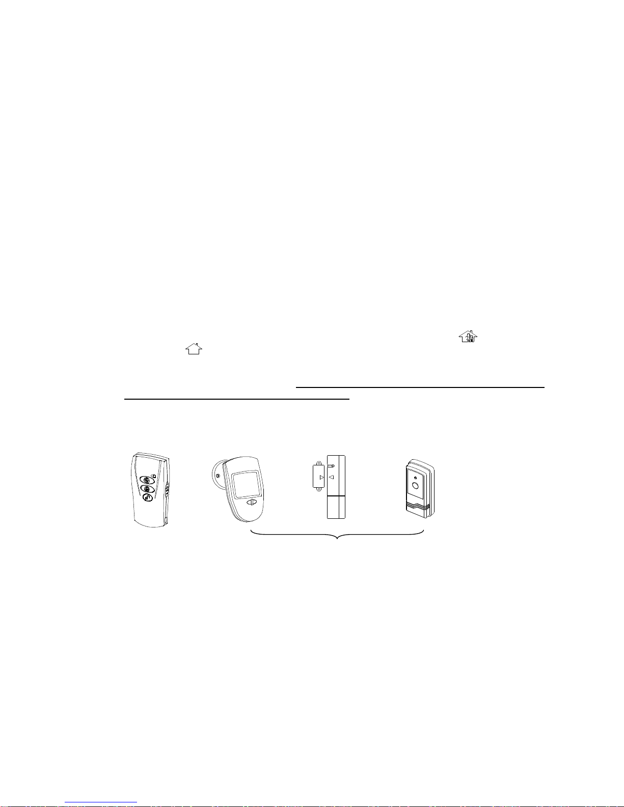
4-key remote controller Wireless PIR detector Door magnetism Medical for help remote controller
Function channel code is “4” function channel code is “2”
3. Telephone dial-up function setting
3.1 press * key, input operation password 0000, and then press SET key to enter the setting mode. Press function
channel key”1”, and then select “1” (the 1st group, that mean you will save the first group phone number you want
dial), input the phone number, for example:8726398, and then press # key to confirm. Then repeat pressing CE key
until “DIDI” sound is heard to exit the setting mode. And then you can test its dial-up function by pressing the key of
the medical for help remote controller or sense the PIR detector. The 2nd/3rd/4
th
group number saving is same as
above, you need only select the “2”(the 2nd group) / “3”(the 3rd group)/ “4”(the 4th group) and then input the
needed number, press #key to confirm and then repeat pressing CE key until “DIDI” sound is heard to exit the
setting mode. We suggest you should test its dial-up function after setting every time.
★★★Please attention: Due to the different installation position and distance (because the wireless
transmission signal is obstructed), you should test them after installation to ensure all detectors and
remote controllers can work normally. Only that can show installation is successful.
If you need use other functions of the system, please read carefully
following instructions!
Page 2
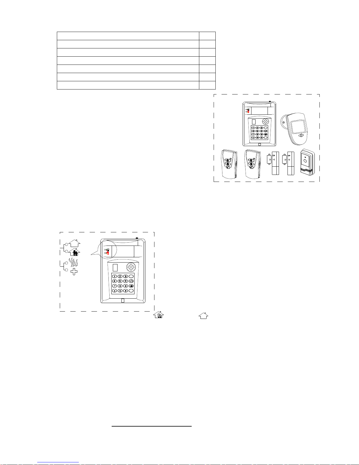
Basic configure
Configure instruction: To strengthen security, besides the
standard configure we provide, you can add other fittings. Our
fittings for your choice have: wireless smoke
alarm(LX98-RF,LX728-RF)\ siren(LX-SR)\ wireless detector(glass
detector LX-AL5, PIR detector(LX-AL6),PIR& glass
detector(LX-AL7), double detector(LX-AL11)\ wired or wireless
detector(LX-AL9)etc.
Main’s specification
Power: power adapter provide DC12V 1A
Standby power: DC12V (chargeable battery groups)
Working frequency: 433MHz
Receiving distance: ≥30m(wide place)
Static current: 30mA
Alarm current: 150 mA
Alarm volume: ≥90db
Sense angle: 120°
Sense distance:9m.max(<24℃)
Installation height:2m-2.5m
Main’s panel instruction
1.AWAY: Away arm, green, Lighting indicate away arm state.
2.HOME: Home arm, red,Lighting indicate home arm state.
3.FIRE: Fire alarm LED, red,it light when smoke/gas/ CO detector is
alarming. After disarm it flash( this is alarm memory state, this
memory function will be cancelled after re-arm)
4.MEDICAL: Medical for help LED,yellow, it light when during medical
alarming. After disarm it flash( this is alarm memory state, this
memory function will be canalled after re-arm)
5.Numeric LED:When display 0-9, it indicate this zone have status
(for example: guard against theft alarming). Numeric LED displays“.”
When panic alarm.
6.0-9、*、#、SET(function setting)、 (home arm)、 (away arm)、CE(Exit setting\return previous
menu)total 16 keys for system setting.
Operation function instruction
1. Switch on power, the controller give ”Di” sound, and then the display window count down 9,8,7…1, and then give
“DiDi” , the controller enter working state. Here it has been in armed state. Press the “disarm” key on remote
controller to disarm system. And then you can operate the main.
2.press* key→input operation password(out factory set to 0000)DI…—DI sound→press SET to enter setting mode.
Special attention: if the main alarm immediately after counting down 9,8,7…1( the wired detector-- include the
main’s sensor have been triggered falsely), here you need disarm the system, and then cover the detection window
of the main with opaque object(like black cloth), for other wired zones you should ensure them to not triggered.
press* key→input operation password→press “SET” →“9”→ “5” re-memorize all wired zone’s state.
3. Set wireless fittings in setting mode, it can set continuously divisionally. The wireless fittings can control the main
only after setting successfully.
4.Wireless zone has 0-9 zones, every zone can be set to indoor/outdoor/24Hr zone/medical alarm type. The
numeric LED display wireless zone “0/1/2…9”
5. Wired zone has 1-4 zones, every zone can be set to indoor/outdoor/24Hr zone type. The numeric LED display
wired zone “1./2./3./4”. The No.1 zone is the main’s sensor.
LX-HS03 main (chargeable battery include) 1pcs
Power adapter(AC220V DC12V 1A) 1pcs
Wireless PIR detector LX-AL8(battery include) 1pcs
Wireless door magnetism LX-DM1(battery include) 2pcs
Single-key remote controllerLX-FS1(battery include) 1pcs
4-key remote controller LX-FS4-V3(battery include) 2pcs
Phone line 1pcs
SET
CE
HOME
AWAY
FIRE
MEDICAL
MEDICAL
FIRE
AWAY
HOME
SET
CE
HOME
AWAY
FIRE
MEDICAL
Page 3

6. Arm mode
a. All the day (24HR) panic for help (fire or medical alarm zone)
b. Away arm: all indoor, outdoor zones be armed
c. Home arm: outdoor zone be armed. When indoor detector is trigged the main will not alarm.
d. Disarm: cancel arm
7. Time-delay setting: you can set the time-delay from the zone be triggered to the main start alarm, 0sec, 10sec,
20sec for your choice.
8. Phone path trouble alarm setting: set whether the main will alarm or not when the phone path has trouble. When
set this alarm ON, 2 DI sounds will be heard every 20sec when path trouble occurred.
9. Dial mode (pulse/tone) can be selected.
10. Audible/inaudible alarm can be set.
11. Dial ON/OFF can be set.
12. Alarm memory function: after zone trigger the main, the main will display the alarmed zone number. The memory
is deleted only after re-arm.
13.automatical dial function:
(1) speech weft and automatically dial instruction:
a The 1-4 group numbers are speech weft telephone number. The number is permit 15bits at most. When alarm, it
dial this 4 group numbers in turns until meet the phone and confirm.
b. The user should pre-set the telephone number and the speech weft information.
c if the main’s telephone number is busy, the main will re-dial when the path is free.
d if the telephone number being dial is busy or none answer, the main will dial next group number after playing
speech 5 times.
e after meeting the phone you will hear corresponding speech information, when speech stop playing ,you can
confirm by pressing the key on the phone according to following:
·press the “*” key, the main stops alarming and you can monitor hearing the scene sound, after “DI” sound you
can press “*” key to continue hearing scene sound otherwise it will automatically ring off after some time.
·press the “0” key, the main stops alarming and ring off automatically.
·press the “#” key, the main ring off automatically but it still alarm.
·press the “7” key, the main ring off automatically and disarm.
Attention: the time-delay of pressing above key should not be below 1sec, otherwise will be invalid
(2) speech information record: you can pre-record the speech content(4 sects at most)
The 1st sect is the content when indoor zone alarm;
The 2nd sect is the content when outdoor zone alarm;
The 3rd sect is the content for fire alarm or 24HR zone alarm
The 4th sect is the content for medical for help.
(3)The speech information will play when status occurs and dialed phone is meet;
14.Long-distance setting
Call the main→After hearing 6 waiting for picking up telephone sounds→ “DIDI” →press * key→ “DI”sound→
input 4-bit operation password on telephone keypad(If input password correctly, you can hear “DIDIDIDI” sound. If
you input it falsely, DIDIDI sound will be heard. And you need press * key to re-input it. You are permitted to input for
3 times) →set by telephone keypad:NOTE: when you press the key on telephone keypad, you should waiting
for DI sound to confirm pressing key effective.
Press 0: ring off;
Press 9: home arm,only outdoor zones armed, and indoor zones not armed
Press 6: away arm, indoor and outdoor zones armed
Press 7: disarm
Press#: ring off and the main alarm
Press*: monitor hearing scene, after DI sound, monitor hearing stop and then:
Press*: continue to monitor hearing
Press0: ring off
Press#: the main alarm and ring off
Press1: return to previous.
Page 4
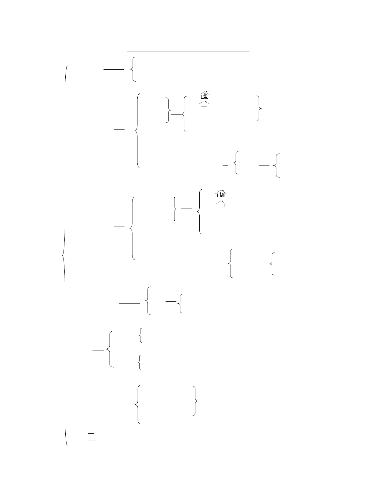
press (set to indoor zone)
press (set to outdoor zone)
press * (set to fire alarm or 24 HR zone)
press # (set to medical alarm)
press 0 (delete zone)
press1 (resume deleted zone)
Press (set to indoor zone)
press (set to outdoor zone)
press * (set to 24HR zone)
press 0 (delete zone)
press 1 (resume deleted zone)
Press 3
(Set wired zone, total 4 zones)
Press 5
press# (set), and then press the remote controller
’
key, the main give DI sound and setting finished.
press0 (delete setting)
Then trigger
the zone, the
main give DI sound and
setting finished.
Press 4 (set remote controller,
can set
total 4 pcs )
Function setting menu(☆you can operate following only in setting mode☆)
Press7 disarm
Press8 modify password, note: should input same 4-bit password twice continually.
Press # (set the time-
delay from wireless zone is
triggerd to the main start alarm)
Press 0 (time-delay is 0 )
Press 1 (time-delay is 10 sec)
Press 2 (time-delay 20 sec)
Press 1 input TEL No. # to save, press 1# to delete
Press 2 input TEL No. # to save, press 2# to delete
Press 3 input TEL No. # to save, press 3# to delete
Press 4 input TEL No. # to save, press 4# to delete
Pres 0 zone
Press 1zone
…
press 9 zone
Press 0 zone
Press 1zone
…
press 9zone
Press 1
press2
press3
press 4
press2
press3
press0(Tel path trouble alarm OFF)
press1(Tel path trouble alarm ON)
press0(pulse dialling)
press1(tone dialling)
Press 1
(set telephone number)
Press 2
(set wireless zone, total 10 zones)
press6(record)
press1(indoor zone record)
press2(outdoor zone record)
press3(fire alarm record)
press4(medical zone record)
press5(play all records)
Pres 1 zone(
the
main’s sensor)
Press 2zone
press 3 zone
Press 4 zone
Press # (set the time-
delay from wired zone is
triggerd to the main start alarm)
Press 1zone(
the
main’s sensor)
Press 2zone
Press 3zone
press 4zone
Press 0 (time-delay is 0 )
Press 1 (time-delay is 10 sec)
Press 2 (time-delay 20 sec)
NOTE
:Press
key, the record time is 5sec; if you
want to keep on recording, you should press and
hold key, the record time is 15sec.
Page 5
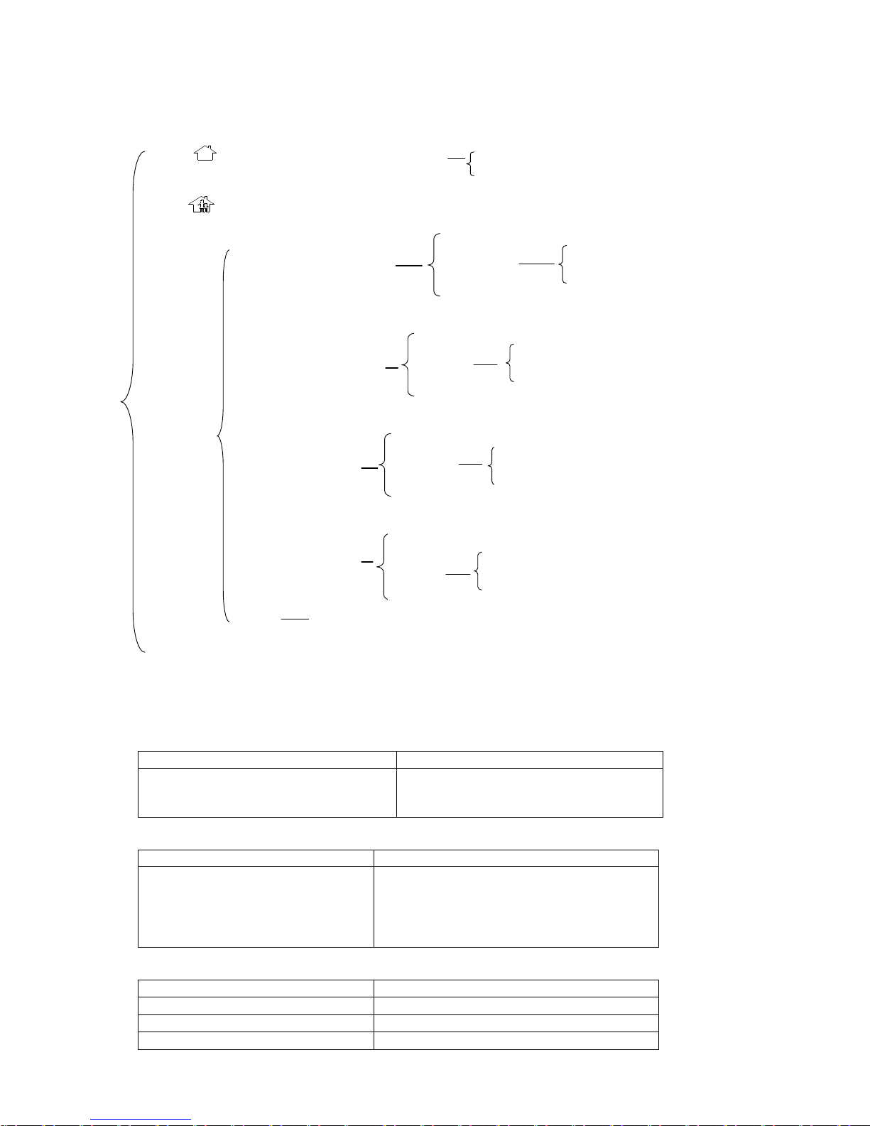
press (away arm, indoor and outdoor zone armed) press0(quick arm)
press1(delay arm)
press (home arm, only outdoor zone armed, and indoor zone not armed)
press 9 ——
NOTE: 1. On above any step, pressing CE key can return to previous.
Function setting mode
(the following is operated in setting mode, if you don’t operate it always, after 20sec it will exit the setting
mode )
NOTE: in setting mode, pressing CE key can return to previous.
(1)enter setting mode
Operation program Voice prompt /LED state
* operation password(it is 0000 when
out-factory)SET
① 2 DI sounds confirm the password;
② 1 DI sound will be heard when enter setting
mode.
(2)set/ modify telephone number
Operation program Voice prompt /LED state
1 1-4(group) TEL number # ① numeric LED will display the saved number
once;
② if you need modify the number, please repeat to
operate this program;
③The number is permit 15bits at most.
(3)delete telephone number
Operation program Voice prompt /LED state
1 1-4 # 2 DI sounds will be heard
Example Result and remarks
1 3 # Delete the 3rd number
press1( set whe
ther the main give
alarm sound after being triggered
by wired zone)
Press 1zone(the main’s sensor)
Press2zone
Press 3zone
Press 4zone
press0(inaudible alarm)
press1(audible alarm)
press2(
set whether the main give
alarm sound after being triggered
by wireless zone)
Press 0zone
Press 1zone
…
Press 9zone
press0(inaudible alarm)
press1(audible alarm)
press3(
set whether the main
dial after being triggered by
wired zone)
Press 1zone(the main’s sensor)
Press 2zone
Press 3zone
Press 4zone
press0(dialing OFF)
press1(dialing ON)
press4(
set whether the
main dial after being
triggered by wireless zone)
Press 0zone
Press 1zone
…
Press 9zone
press0(dialingOFF)
press1(dialing ON)
press5
Re-memorize wired zone’s state and need not re-switch off and on power.
Page 6
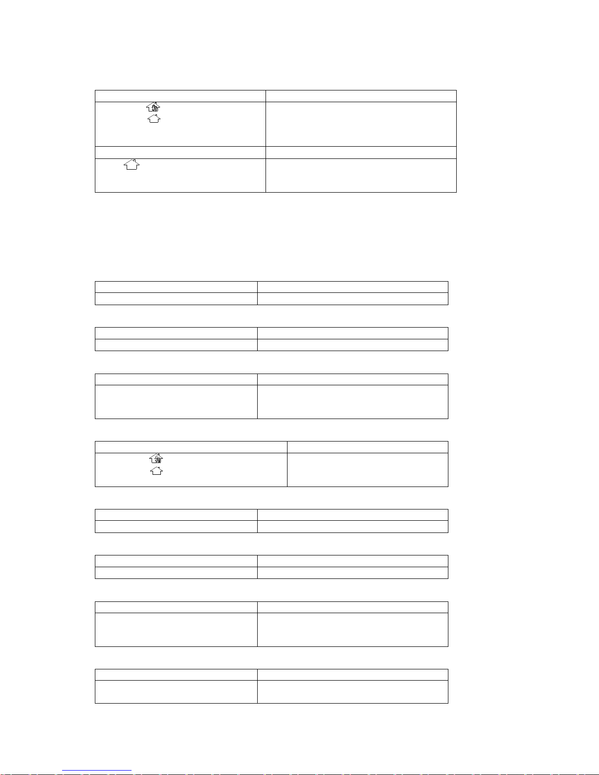
(4)set wireless zone: The wireless zone can control the main only after setting.
Operation program Voice prompt /LED state
2 0-9(zone) :set to indoor zone
:set to outdoor zone
* :set to fire or 24HR zone
# : set to medical zone
And then trigger the wireless detector emit
signal to the main. 1 DI sound will be heard and
setting successfully.
Example Result and remarks
2 1 Sense the LX-AL8 and make it emit signal. 1 DI
sound will be heard. So this LX-AL8 is set to No.1
zone and is outdoor zone
Set wireless zone attention:
◇ If the zones having set need to set another type, at first you should delete the zone having set and then set to
another type.
◇ If the coding of the zone needing set is same as the coding of zone having set, during setting “DiDi…” sound will
be heard, and the numerical LED display the zone number Having set, the zone can not be set. Here you can
revise its coding or delete the zone having set and then re-set).
(5)delete wireless zone
Operation program remarks
2 0-9(zone) 0 Delete wireless zone
(6)resume deleted wireless zone
Operation program remarks
2 0-9(zone) 1 Resume deleted wireless zone
(7)wireless zone time-delay setting
Operation program remarks
2 # 0-9(zone) 0(0sec)
1(10sec)
2(20sec)
Set the time-delay from wireless zone is triggered
to the main start alarm
(8)set wired zone
Operation program remarks
3 1-4(zone) : set to indoor zone
set to outdoor zone
* : set to 24HR zone
Set the type of wired zone having
connected with the main
NOTE: No.1 zone is the main’s sensor.
(9)delete wired zone
Operation program remarks
3 1-4(zone) 0 Delete wired zone
(10)resume deleted wired zone
Operation program remarks
3 1-4(zone) 1 Resume deleted wired zone
(11)wired zone time-delay setting
Operation program remarks
3 # 1-4(zone) 0(0sec)
1(10sec)
2(20sec)
Set the time-delay from wired zone is triggered to
the main start alarm
(12)set remote controller the remote controller can control the main only after setting.
Operation program Voice prompt /LED state
4 1-4 # And then press the emitting key, 1 DI sound will
be heard and setting successfully.
Set remote controller attention:
◇ You can set 4-group remote controllers with different coding.
Page 7
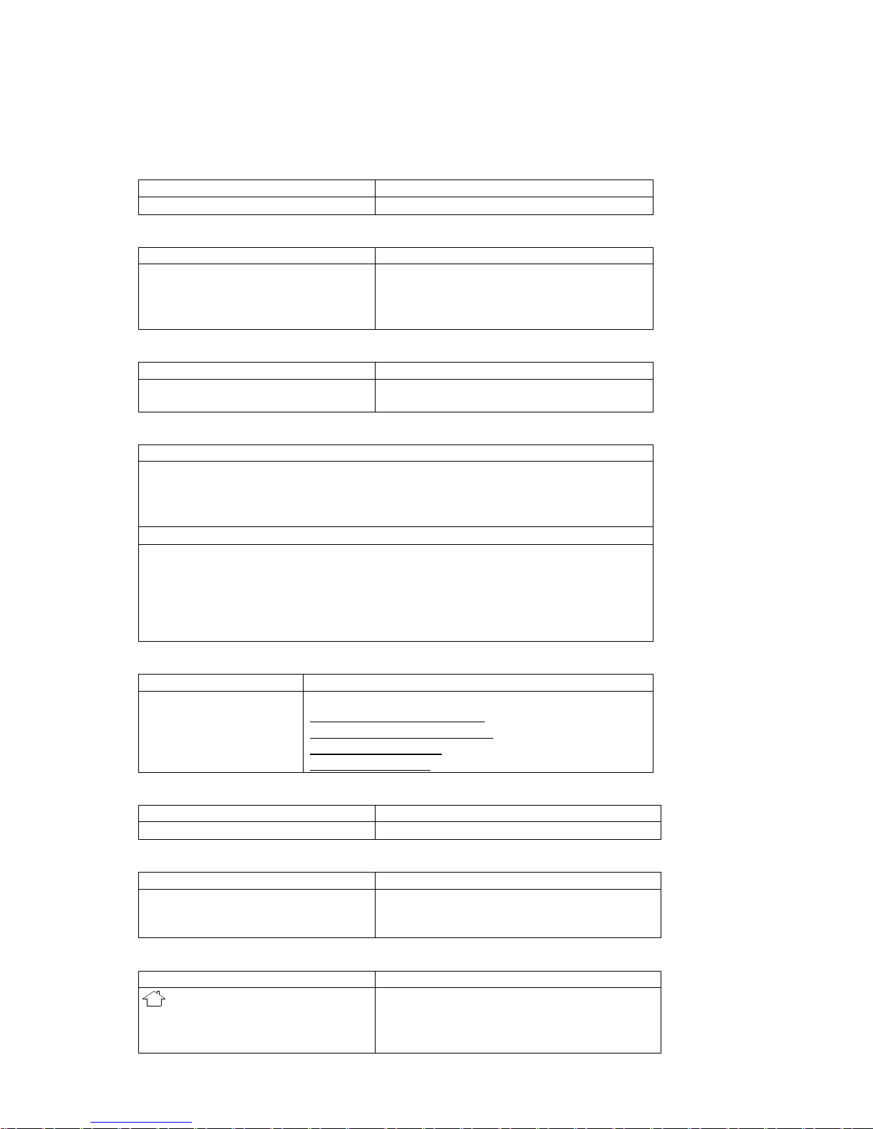
◇If the remote controllers having set need set to another number, you should delete the remote controllers having
studied and then set again.
◇ If the coding of the remote controllers needing set is same as the coding of remote controllers having set, during
setting “DiDi…” sound will be heard, and the numerical LED display the remote controllers number having set, the
remote controllers can not be set. Here you can revise its coding or delete the remote controllers having set and
then re-set).
(13)delete remote controller
Operation program Voice prompt /LED state
4 1-4 0 2 DI sounds confirm deleting
(14)Tel path trouble alarm setting
Operation program remarks
5 2 0(OFF)
1(ON)
set whether the main will alarm or not when the
phone path has trouble. When set this alarm
ON, 2 DI sounds will be heard every 20sec
when path trouble occurred.
(15)dial-up mode setting
Operation program remarks
5 3 0(pulse)
1(tone)
Set pulse/ tone dial-up mode
(16)speech information record: you can pre-record the speech content(4 sects at most)
Operation program
6 1 indoor zone record(example: here status occur, please succor)
2 outdoor zone record (example: robber enter, please call the police)
3 fire alarm or 24HR zone record( example: fire occur, please succor)
4 medical zone record(please call ambulance)
Voice prompt/LED state
1 DI sound prompt you start recording, facing the main leaves the words, 1 DI sound prompt
record time over. After record finished, The recorded content will be played automatically
once.
NOTE:◇record time default is 5sec, if you want to keep on recording, you should press and
hold the key. The record time is 15sec.
◇ the system only save the last recorded content of every sect.
(17)play all records
Operation program Voice prompt/LED state
6 5 Example, the main will play in turns:
here status occur, please succor(numeric LED display”1”);
robber enter, please call the police(numeric LED display”2”);
fire occur, please succor(numeric LED display”3”);
please call ambulance(numeric LED display”4”).
(18)disarm
Operation program Voice prompt/LED state
7 2 DI sound will be heard
(19)modify operate password
Operation program Voice prompt/LED state
8 You need input same new password (4-bit) twice,
after inputting the numeric LED will display the new
password once.
(20)away arm
Operation program Voice prompt/LED state
0(quick arm)
1(delay arm)
Quick arm: 1 DI sound enter arm state, AWAY LED
light.
delay arm: numeric LED flash, AWAY LED light,
after 60sec, 1 DI sound enter arm state
Page 8
(21)home arm
Operation program Voice prompt/LED state
1 DI sound enter arm state, HOME LED light.
(22)wired zone inaudible/audible alarm setting
Operation program remarks
9 1 1-4 0 inaudible alarm
1 audible alarm
Set whether the main give alarm sound or not
when wired zone is triggered.
(23)wireless zone inaudible/audible alarm setting
Operation program remarks
9 2 0-9 0 inaudible alarm
1 audible alarm
Set whether the main give alarm sound or not
when wireless zone is triggered.
(24)set whether the main dial or not when wired zone be triggered
Operation program remarks
9 3 1-4 0 dial OFF
1 dial ON
set whether the main dial or not when wired zone
be triggered
(25)set whether the main dial or not when wireless zone be triggered
Operation program remarks
9 4 0-9 0 dial OFF
1 dial ON
set whether the main dial or not when wireless
zone be triggered
(26)re-memorize wired zone’s state
Operation program Voice prompt/LED state
9 5 1 DI sound confirm.
Special attention: if the main alarm immediately
after counting down 9,8,7…1( the wired detectors
have been triggered falsely), here you need disarm
the system, and ensure wired zones not be
triggered. Then according to this method
re-memorize all wired zone’s state.
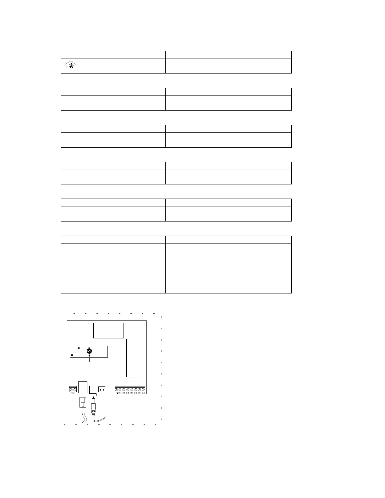
Interior PCB configure
1. DC12V power output terminal, do not use the terminal for power
supply as possible as you can,
2. Phone line jack: provide for out-connect automatic dial-up for help;
3. DC power input terminal, connect with power adapter.the adapter
requires: input 220VAC, output 12VDC, and current 1000mA.
During AC power is on, standby battery will be charged
automatically. When AC power cut off, the product works by
standby battery entirely.
4. Standby power jack;
5. Connect wired fittings, please reference the instruction of
out-connect wired fittings;
6. CPU 7. Speech module
8. Receiving module; 9. Adjustable inductance
9
8
5
4
3
2
1
7
6
Page 9
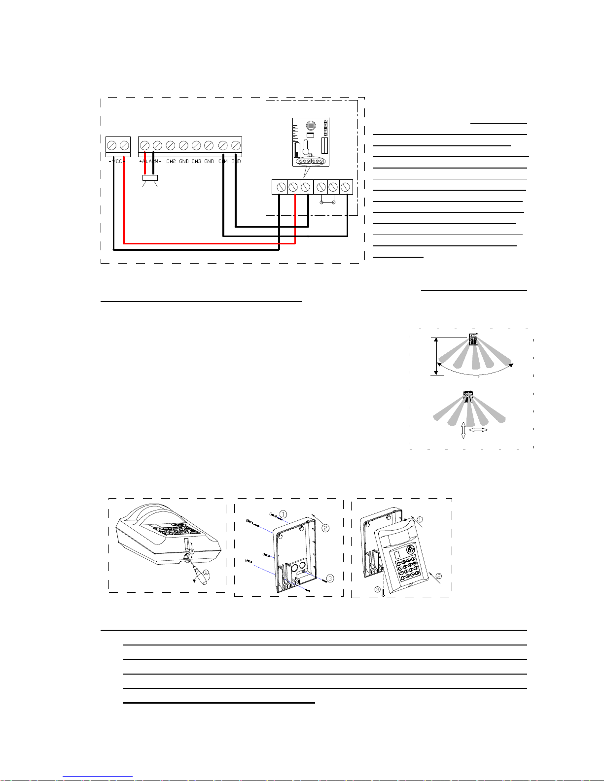
Out-connect wired fittings (see the following diagram)
1. CH2-GND, CH3-GND, CH4-GND
terminal----channel 2~4, connect wired
detector’s output terminal, NOTE: switch
on power, there are about 45 seconds
for all out-connect wired zones to
enter stable state. After this time-delay,
the main will memorize all wired zones
on “not alarm” state.(attention: during
this 45sec time-delay, you should not
trigger any zone, otherwise the main
will memorize zones’ being triggered
state to “not alarm” state falsely. If
memorize falsely, you can switch off
power and then switch on power to
re-memorize;
2. “+ALARM-” terminal----connect with
siren (voltage DC12V, current <800mA);
3. “-VCC+ “terminal---power output terminal. That can supply power for wired detector, but you should not use the
terminal for power supply as possible as you can;
The main’s Installation
⑴At first you should select suitable installing position, the sensor’s sensitivity is
very high to human body’s moving breadthwise( like right fig.).And it is very low to
moving frontal. So when installing it , you should select a position that moving
object can move breadthwise to the sensor, so that the sensor lamp work reliably.
⑵With screwdriver tighten off the bottom screw, and then insert a flat-screw into
middle slot and pull up it to open the front cover (fig 1).
⑶Place the front cover with PCB on safe position avoiding other objects in.
⑷On installing position mark installing hole, and then drill holes according to the
mark;
⑸insert the standby power plug onto the standby power jack(see the 4 of the
interior PCB configure),put outer lines through outlet-line hole and connect line
according to out-connect wired fitting figure.
⑹Fixing back cover on installing position according to fig.2;
⑺Make front cover top aim at back cover top and close, then button up bottom and tighten the screw(fig 3).
★★★warning: during you open the unit to install, do not touch the adjustable
inductance on PCB(see the “9” of the interior PCB configure), otherwise that
will effect the main’s receiving frequency and lead its receiving distance
become short. If you find the receiving distance is short, maybe you have
touched the inductance. Here we suggest the professional installation
person micro-adjust the inductance.
siren
+ -
13ONPULSELEDOFF
-4
-6
0
4
2
-2
TAMPER
+
_
RELAY
wired detectorLX-AL6
_
12VDC+
RELAYTAMPER
fig. 2
fig. 3
fig. 1
110
breadthwise move,
sensitivity high
frontal move,
sensitivity low
install
height
2m~2.5m
Page 10
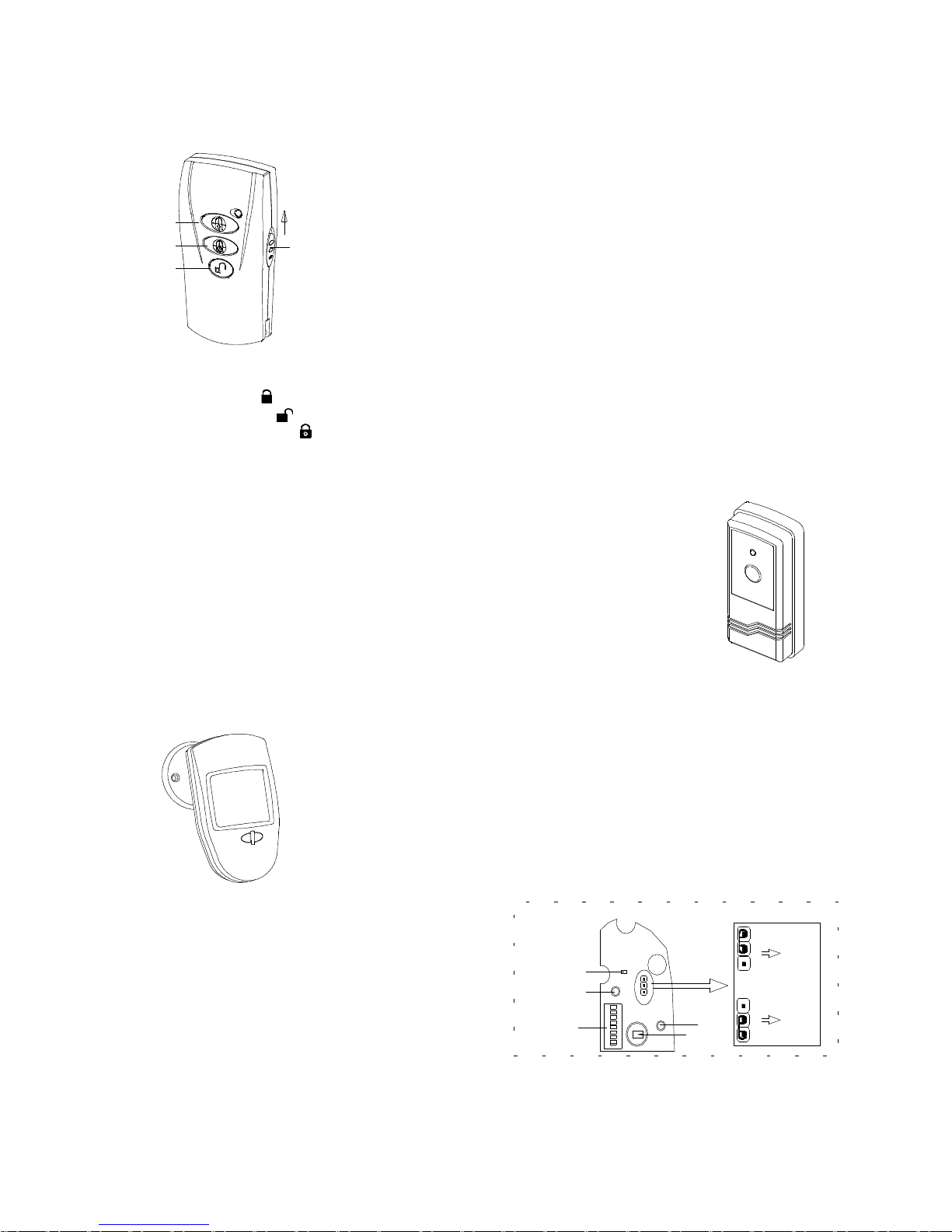
4-key remote controller LX-FS4-V3
1.specification
①power:DC3V ( lithium battery)
②static current: <1μA emitting current:<8mA
③remote control distance: ≥30m(wide place)
2.operate
①at first set its code. It adapts free coding. The coding method: tighten off the
base screw and open it, press and hold any emission key and then install battery,
here the LED flash indicating it is coding. The coding is confirmed when you
loosen the key.( if you find remote controllers have repeat codlings, you can
re-code according above method).
②wireless setting: Enter “set remote controller” in setting mode, press any
emitting key to make it emit signal, and the main will give 1 DI sound, setting
successfully.
③key function:
◇push up the panic key, the main give panic alarm, and also it dial numbers by turns.
◇Press arm key : Away/home arm, the corresponding HOME,AWAY LED light.
◇Press disarm key : Cancel arm, and also can intermit alarming and dialing.
◇Press delay arm key : the main give DI—DI sound, and after 60sec, DI sound will be heard again, enter armed,
AWAY LED light.
Single-key remote controller LX-FS1:it is designed for medical alarm.
1.specification
①power:DC12V A23 battery
②static current: 0μA emitting current:<4mA
③remote control distance: ≥30m(wide place)
2.operation
① wireless setting: Enter “set wireless zone” in setting mode and select “set to medical
alarm”, press emitting key to make it emit signal, and the main will give 1 DI sound, setting
successfully.
②Press it 3 times within 15sec(When pressing it, the MEDICAL LED light.). And the main
will alarm and dial. The MEDICAL LED light.
Wireless infrared motion detector LX-AL8
1.specification
power:DC9V 6F22 battery detect angle:110°
static current:30μA remote control distance:≥30m(wide place)
detect distance:12m installation height:2m
2.function
①prevent false-alarm function: you can set sense once/twice to emit;
②sense、emission LED
③Low-battery LED: When battery energy is below 7V, the low-battery LED will flash once a
second and remind you replace battery.
3.jumper setting( see right diagram)
①sense once to emit:
Sense once, the unit emit signal,15sec later after it emit
signal. Sense it once again, the unit emit signal again;
②sense twice to emit:
Sense twice, the unit emit signal, 15sec later after
it emit signal. Sense it twice again, the unit emit
signal again; this setting enhance its preventing
false-alarm and preventing-pet function.
4.operate and install
◇switch on 9V battery, after 60sec the unit enter working state;
◇set its coding by DIP switch;
◇wireless setting: Enter “set wireless zone” in setting mode, sway your hand in front of the detecting window to
make it emit signal, and the main will give 1 DI sound, setting successfully.
◇we suggest it should be installed in dypass, living room, reside room etc area, and install it on high place. Its
AUTO
DIP switch
Sense LED
PIR
Jumper
AUTO / 1
AUTO / 1
1
Emit LED
Sense
once to
emit
Sense
twice to
emit
Low-battery LED
panic
disarm
delay arm
arm
push up
Page 11
detecting window should face the detection range.
◇Avoid installing the unit on metal base;
◇Avoid installing the unit where sun shine or temperature change obviously, for example: air conditioning, heater
etc.
Wireless door magnetism LX-DM1
1.specification
①power:DC12V A23 battery
②static current: 0μA emission current: <8mA
③remote control distance: ≥30m(wide place)
2.function
①it transmit the signal of the door/ window’s opening or closing to the main;
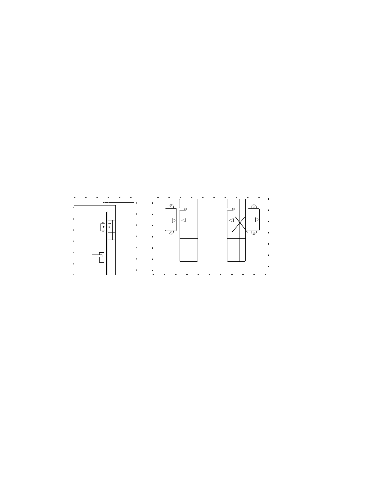
②Tamper design: Under the condition that the triangle on emitter aims at triangle on magnetism, when the battery
lid is removed, it will emit signal to the main.
3.operate
① Set its coding by DIP switch;
② Wireless setting: enter “set wireless zone” in setting mode, the triangle on emitter aims at triangle on magnetism,
put away the magnetism or emitter to make it emit signal, and the main will give 1 DI sound, setting
successfully.
4.Installation attention
◇ Install magnetism and emitter on upright position of door lock, the distance between them is 3mm~5mm and
triangle on emitter aims at triangle on magnetism(like left following figure);
◇ The magnetism should be on the left of the emitter (like right following figure).
3mm~5mm
correct using incorrect using
 Loading...