

Lexicomm ViLX-EX8 Installation And Commissioning Manual
Lexicomm ViLX-EX8 EVCS
System Expander Panel
Installation and Commissioning Manual
Version 1- October 2017

Table of Contents
1 Introduction .......................................................................................................................... 3
1.1 What is an Emergency Voice Communication System ........................................................ 3
1.2 Suitability ...................................................................................................................... 3
2 Product Overview .................................................................................................................. 3
3 Important Safety Information ................................................................................................. 4
3.1 Unpacking the ViLX-EX8 ................................................................................................. 4
4 Installation ........................................................................................................................... 5
4.1 Connecting the ViLX-EX8 System Expander panel .............................................................. 5
4.2 Planning the Wiring ........................................................................................................ 6
4.3 Cable and Wiring Guidance ............................................................................................. 6
4.3.1 Fire Telephone system ............................................................................................ 6
4.3.2 Disabled Refuge EVC System................................................................................... 6
4.3.3 Combined Systems ................................................................................................. 6
4.3.4 “Assist Call” Emergency Assistance Alarm Systems .................................................... 6
4.4 Cabling methods ............................................................................................................ 6
4.4.1 ViLX-EX8 System Expander Panel Wiring .................................................................. 7
4.4.2 ViLX-TMS Master, ViLX-EX8 System Expander Panel wiring in ring .............................. 7
4.4.3 Mains Connection ................................................................................................... 8
4.5 Battery Information ........................................................................................................ 8
4.6 Outstation Connections ................................................................................................... 9
4.6.1 Type A outstation ................................................................................................... 9
4.6.2 Type B outstation ................................................................................................... 9
4.6.3 “Assist Call” ACA Accessible Toilet Kit ..................................................................... 10
4.6.4 Enable Switch Input ............................................................................................. 10
4.7 TMS Auxiliary Connections ............................................................................................ 10
4.8 Powering up procedure ................................................................................................. 10
4.9 Powering down procedure ............................................................................................ 10
5 Hardware configuration procedure ........................................................................................ 11
5.1 Exchange PCB Dipswitch Settings .................................................................................. 11
6 Indications .......................................................................................................................... 12
6.1 Mode Indicator Summary .............................................................................................. 12
6.2 Power supply and CPU indicator Summary...................................................................... 12
6.3 Zone Indicator Summary .............................................................................................. 12
7 Commissioning pro c edu r e .................................................................................................... 13
8 Maintenance ....................................................................................................................... 13
Notes .......................................................................................................................................... 14
Notes .......................................................................................................................................... 15
9 Technical Specification ......................................................................................................... 16
Document PViLXEX8 7001-01 Rev 1 2017 Page 2 of 16

1 Introduction
1.1 What is an Emergency Voice Communication System
An Emergency Voice Communication System, or EVCS, is a system that allows voice communication in
either direction between a central control point and a number of other points throughout a building or
building complex, particularly in an emergency situation. The control points, or outstations by which
they are more commonly referred, generally comprise of a Type A outstation, a Type B outstation, or a
Type C Combined Type outstation. “Assist Call” em er g en cy assistance alarm systems can also be
incorporated into the EVCS.
EVCS is generally required in the following situations:
In any building or sports or similar venue where there are disabled people, or people who may
have difficulty negotiating the evacuation route.
In buildings with phased evacuation and/or firefighting lifts where it facilitates secure
communications for building managers, fire wardens , and attend i ng fire office rs .
At sports venues and similar complexes, where it will assist stewards in controlling the
evacuation of the area in an emergency.
The Lexicomm ViLX-TMS Emergency Voice Communications System (EVCS) is designed to fully comply
with BS5839 Part 9:2011 for use as a Fire Telephone system, Disabled Refuge Call system or as a
combined system when both Fire Telephones and Disabled Refuge Points are required.
1.2 Suitability
Fire telephone systems are recommended for all public buildings and multi-story buildings over four
floors by BS9999.
Disabled Refuge systems are required in buildings where the public or disabled staff gain access to any
floor other than the ground floor using lifts . Refuge areas are provided at each storey exit from each
protected stairway.
2 Product Over view
The Lexicomm EVCS has been designed around a total network concept so all of the Lexicomm panels
have inbuilt networking.
The system comprises 3 types of panel; ViLX-TMS touch screen master station (hereafter referred to as
TMS), the ViLX-228 2 to 8 line master station (hereafter referred to as LX228) and a ViLX-EX8 system
expander panel (hereafter referred to as EX8). For Lexicomm systems in excess of 8 lines a TMS must
be used as the master station, the system can then be expanded by the use of a EX8 or LX228 in blocks
of 8 lines up to a maximum system capacity of 512 lines. Additional TMS panels can be used wherever
indication and control is requi red i.e. Fire Control rooms and building reception.
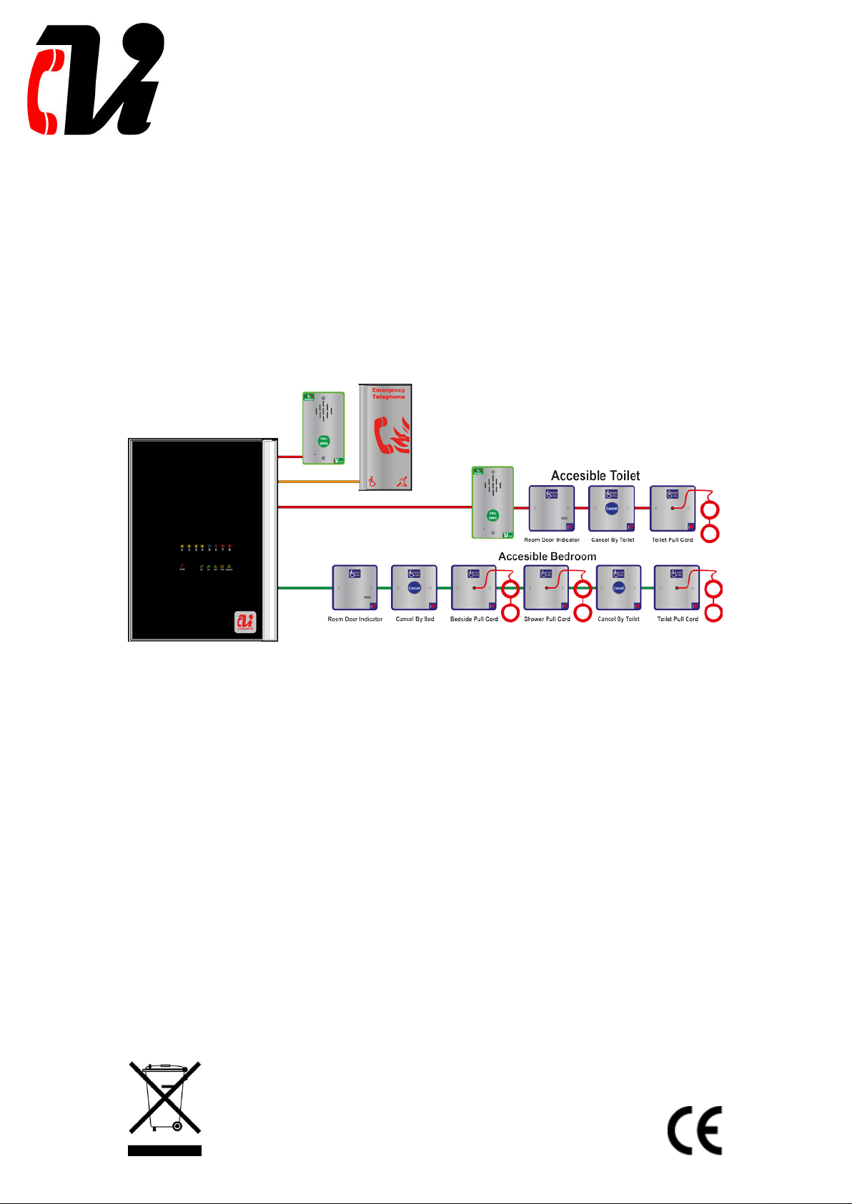
The wiring is a ring and spur topology with outstations being wired on radial spurs from any master
station or system expander panel. The EX-8 and any TMS or LX228 are wired in a ring network up to a
maximum of 64. The EX-8 would typically be sited in convenient locations close to the outstations i.e.
risers or stairwells resulting in short vertical wiring runs. The LX228 can be used to provide local control
of up to 8 lines within a building this can then report back to a TMS which can provide overall control of
an entire site.
In this way a very large system can be completed with a minimum of cabling coming back the master
station via the network ring.
Additionally the “Assist Call” emergency assistance alarm system can either be connected to the same
line with an outstation, or connected to a de dicated line. Neither the outstations nor the “Assist Call”
emergency alarm system require a separate power supply unit as each line is powered from the Master
Station. This has the additional benefit of each line being fully monitored and battery backed up.
Page 3 of 16 Document PViLXEX8 7001-01 Rev 1 2017
Caution
Indoor Use Only
Shock HazardIsolate Before Opening
TO REDUCE THE RISK OF FIRE OR ELECTRIC
OR MOISTURE
Warning
THIS UNIT MUST BE EARTHED
Warning
NO USER SERVICEABLE PARTS
3 Important Safety Informati on
This Equipment must only be installed and maintained by a suitably skilled and competent person.
This Equipment is defined as Class 1 in EN60065 (Low Voltage Directive) and must be EARTHED.
Warning
Warning
Each TMS and EX8 requires a 3A spur, returning to a breaker clearly marked “EVCS DO NOT TURN
OFF”.
If the TMS, LX228 and the EX-8 are distributed aro u n d a sit e , it is essential that all panels are on the
same mains phase, as they are classified TEN 230V. Powering from different phases can mean a 440V
potential can be present in a panel during a major fault incident.
Anti-static handling guidelines
Make sure that electrostatic handling precautions are taken immediately before handling PCBs and other
static sensitive components.
Before handling any static-sensitive items, operators should get rid of any electrostatic charge by
touching a sound safety earth. Always handle PCBs by their sides and avoid touching any components.
SHOCK, DO NOT EXPOSE THIS UNIT TO RAIN
3.1 Unpacking the ViLX-EX8
Remove the EX-8 from its packing, and check the contents against the following list:
• ViLX-EX8 System Expander Panel.
• Accessory pack with the following contents:-
o 1 number 2.5mm AF Hex Key.
o 8off 10K End of Line (EoL) Resistors .
o Installation and Commissioning Manual ( this document)
Use the 2.5mm AF Hex Key supplied to open the right hand front cover.
Verify the following items are present:
• 4 number Line cards c/w 2 way line connector.
• 1 number 2 way Fault connector.
• 1 number 2 way In Use connector.
• 1 number 2 way Enable connector.
• 4 number 2 way Network connectors.
• 1 number 3 way mains connector.
• 1 number battery lead.
Document PViLXEX8 7001-01 Rev 1 2017 Page 4 of 16
4 Installation
4.1 Connecting the ViLX-EX8 System Expander panel
To comply with EMC (Electro Magnetic Compatibility) regulations and to reduce the risk of electrical
interference in the system wiring, the use of fire-resistant screened cables is recommended throughout
the installation.
All wiring should come into the enclosure via the knockouts provided , and be fixed tidily to the relevant
terminals.
Note that correct cable glanding is essential. Due regard should be paid to any system specifications
which demand a certain cable t ype, providing it meets the appropriate national wiring regulations.
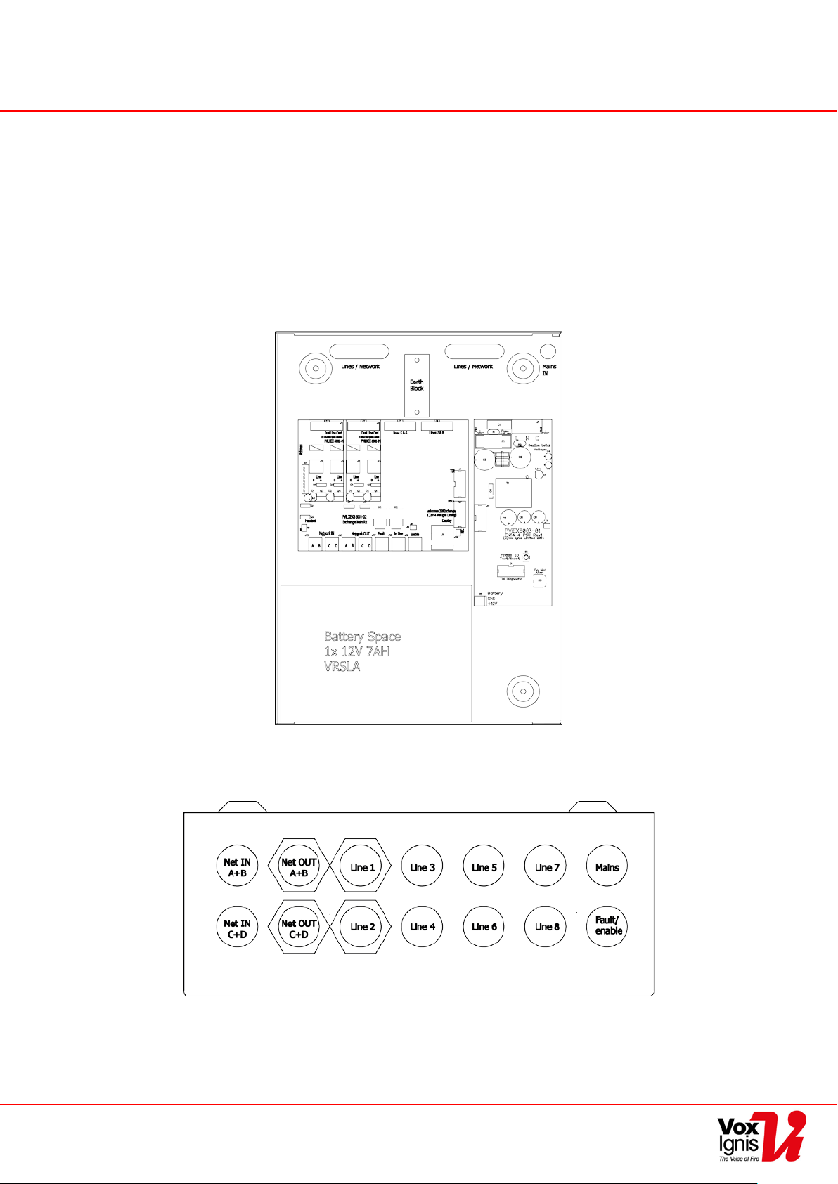
Prior to mounting the EX8, it should be decided if the field wiring is to be run on the surface or
concealed. There are 14 knockouts on the top and 2 slotted entries with a dedicated mains supply
entry at the rear. If a knockout is removed by mistake, fill the hole with a good quality cable gland.
Unused knockouts must be left unopened to comply with the Low Voltage Directive. Accidentally
knocked out holes should be blanked off.
The ViLX-EX8 weighs 5kg with batteries, so care should be taken to securely mount the Station on stud
walling.
Page 5 of 16 Document PViLXEX8 7001-01 Rev 1 2017
 Loading...