

Lexicomm ViLX-228 Installation And Commissioning Manual
Lexicomm ViLX-228 EV CS
Master Station
Installation and Commissioning Manual
Version 6 September 2017

Table of Contents
1. Introduction ............................................................................................................................... 3
1.1 What is an Emergency Voice Communication System .............................................................. 3
1.2 Suitability ............................................................................................................................ 3
2. Product Overview ....................................................................................................................... 3
3. Important Safety Information ...................................................................................................... 4
4. Unpacking the Unit ..................................................................................................................... 5
5. Installation ................................................................................................................................ 6
5.1 Connecting the ViLX-228 Master Station ................................................................................. 7
5.2 Planning the Wiring .............................................................................................................. 7
5.3 Cable and Wiring Guidance ................................................................................................... 7
5.3.1 Fire Telephone system .................................................................................................. 7
5.3.2 Disabled Refuge EVC System ......................................................................................... 7
5.3.3 Combined Systems ........................................................................................................ 7
5.3.4 “Assist Call” Emergency Assistance Alarm Systems ........................................................... 7
5.4 Cabling methods .................................................................................................................. 7
5.4.1 ViLX-228 Master Station Wiring ...................................................................................... 8
5.4.2 ViLX-228 Master/Repeater Stations wiring in ring ............................................................. 9
5.5 Mains Connection ............................................................................................................... 10
5.6 Battery Information ............................................................................................................ 10
5.7 Outstation Connections ....................................................................................................... 10
5.7.1 Type A outstation........................................................................................................ 11
5.7.2 Type B outstation ........................................................................................................ 11
5.7.3 ACA Accessible Toilet Kit .............................................................................................. 11
5.8 Auxiliary Connections ......................................................................................................... 12
5.9 Powering up procedure ....................................................................................................... 12
5.10 Powering down procedure ................................................................................................. 12
6. Set up procedure ..................................................................................................................... 13
6.1 ViLX-228 Master Station Display PCB Dipswitch Settings ........................................................ 13
6.2 Adding a Line Card ............................................................................................................. 14
6.3 Removing a Line card ......................................................................................................... 14
6.4 Adding a ViLX-228 Repeater Station ..................................................................................... 14
ViLX-228 Master Station Exchange PCB Dipswitch Settings .......................................................... 15
7. System Menus ......................................................................................................................... 16
7.1 Fault Accept ...................................................................................................................... 16
7.2 Panel Indicator Test ........................................................................................................... 16
7.3 Extended Fault Menu .......................................................................................................... 16
7.4 Line Identify ...................................................................................................................... 16
7.5 Engineer Walk Test ............................................................................................................ 17
7.6 Remote Signal Delay Timer ................................................................................................. 17
7.7 In Use Relay Options .......................................................................................................... 18
8. Operation ................................................................................................................................ 18
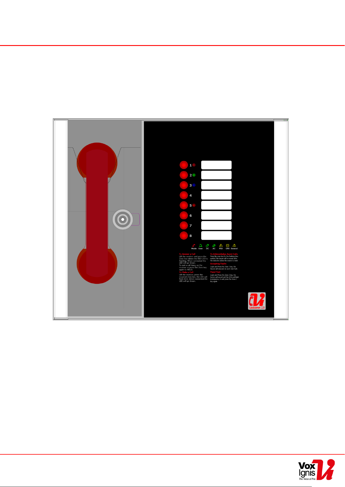
8.1 Receiving a call .................................................................................................................. 18
8.2 Making a call ..................................................................................................................... 18
8.3 Ending a call ...................................................................................................................... 18
8.4 Putting a call on hold .......................................................................................................... 18
8.5 Conference Call .................................................................................................................. 18
8.6 Acknowledging “Assist Call” alarms ...................................................................................... 19
8.7 Accepting Faults ................................................................................................................. 19
8.8 Panel Indicator Test ........................................................................................................... 19
9. Indications and Controls ........................................................................................................... 19
9.1 Mode Indicator Summary .................................................................................................... 19
9.2 Power supply and CPU indicator Summary ............................................................................ 20
9.3 User Indicator Summary ..................................................................................................... 20
9.4 Zone indicator summary ..................................................................................................... 20
10. Commissioning procedure ....................................................................................................... 21
11. Maintenance .......................................................................................................................... 21
12. Outstation zone template ........................................................................................................ 22
13. Technical Specification ............................................................................................................ 24
Document PViLX228 7001-06 Rev 6 2017 Page 2 of 24

1. Introduction
1.1 What is an Emergency Voice Communication System
An Emergency Voice Communication System, or EVCS, is a system that allows voice communication in
either direction between a central control point and a number of other points throughout a building or
building complex, particularly in a fire emergency situation. The control points, or outstations by which
they are more commonly referred, generally comprise of a Type A outstation, a Type B outstation, or a
Type C Combined Type outstation. “Assist Call” em er g en cy assistance alarm systems can also be
incorporated into the EVCS.
EVCS is generally required in the following situations:
• In any building or sports or similar venue where there are disabled people, or people who may
have difficulty negotiating the evacuation route.
• In buildings with phased evacuation and/or firefighting lifts where it facilitates secure
communications for building managers, fire wardens , and attend i ng fire office rs .
• At sports venues and similar complexes, where it will assist stewards in controlling the
evacuation of the area in an emergency.
The Lexicomm ViLX-228 Emergency Voice Communications System (EVCS) is designed to fully comply
with BS5839 Part 9:2011 for use as a Fire Telephone system, Disabled Refuge Call system or as a
combined system when both Fire Telephones and Disabled Refuge Points are required.
1.2 Suitability
Fire telephone systems are recommended for all public buildings and multi-story buildings over four
floors by BS9999.
Disabled Refuge systems are required in buildings where the public or disabled staff gains access to any
floor other than the ground floor using lifts . Refuge areas are provided at each storey exit from each
protected stairway.
2. Product Overview
The Lexicomm EVCS, or ViLX-228, comprises of a Master Station and one or more outstations.
Additionally the “Assist Call” emergency assistance alarm system can either be connected to the same
line as a Type B outstation, or connected to a dedicated line. Neither the outstations nor the “Assist
Call” emergency alarm system require a separate power supply unit as each line is powered from the
Master Station. This has the additional benefit of each line being fully monitored and battery backed up.
Each ViLX-228 Master Station can also perform as a ViLX-228 Repeater Station. A ViLX-228 Repeater
Station mimics the ViLX-228 Master Station both in operation and indication. Any reference in this
document to the ViLX-228 Master Station also applies to the ViLX-228 Repeater Station, unless specified
otherwise.
The ViLX-228 Master Station has been designed for radial star topology. In most cases this will reduce
the cable requirements for all ring-based systems. The topology consists of spurs formed of 1 off two
core 1.5mm CSA cables (soft skin enhanced up to 500m per leg, MICC 200m per leg) to each
outstation.
Page 3 of 24 Document PViLX228 7001-06 Rev 6 2017
Caution
Indoor Use Only
Shock HazardIsolate Before Opening
TO REDUCE THE RISK OF FIRE OR ELECTRIC
OR MOISTURE
Warning
THIS UNIT MUST BE EARTHED
Warning
NO USER SERVICEABLE PARTS
3. Important Safety Information
This Equipment must only be installed and maintained by a suitably skilled and competent person.
This Equipment is defined as Class 1 in EN60065 (Low Voltage Directive) and must be EARTHED.
Warning
Warning
Each ViLX-228 Master/Repeater Station require s a 3A spu r , r etu r n in g to a breaker clearly marke d “EVCS
DO NOT TURN OFF”.
If the ViLX-228 Master Station and the ViLX-228 Repeater Station are distributed around a site, it is
essential that both ViLX-228 Stations are on the same mains phase, as they are classified TEN 230V.
Powering from different phases can mean a 440V potential can be present in a ViLX-228 Station during
a major fault incident.
Make sure that electrostatic handling precautions are taken immediately before handling PCBs and other
static sensitive components.
Before handling any static-sensitive items, operators should get rid of any electrostatic charge by
touching a sound safety earth. Always handle PCBs by their sides and avoid touching any components.
SHOCK, DO NOT EXPOSE THIS UNIT TO RAIN
Anti-static handling guideli n es
Document PViLX228 7001-06 Rev 6 2017 Page 4 of 24
4. Unpacking the Unit
Remove the ViLX-228 Master Station from its packing, and check the contents against the following list:
• ViLX-228 Master Station.
• Installation & maintenance manual (this document).
• User Guide & logbook.
• Accessory pack with the following contents:-
o 1 number 2.5mm AF Hex Key.
o 1 number door handle/key.
o End of Line (EoL) Resistors, 2 per line card
Use the 2.5mm AF Hex Key supplied to open the right hand front cover.
Verify the following items are present:
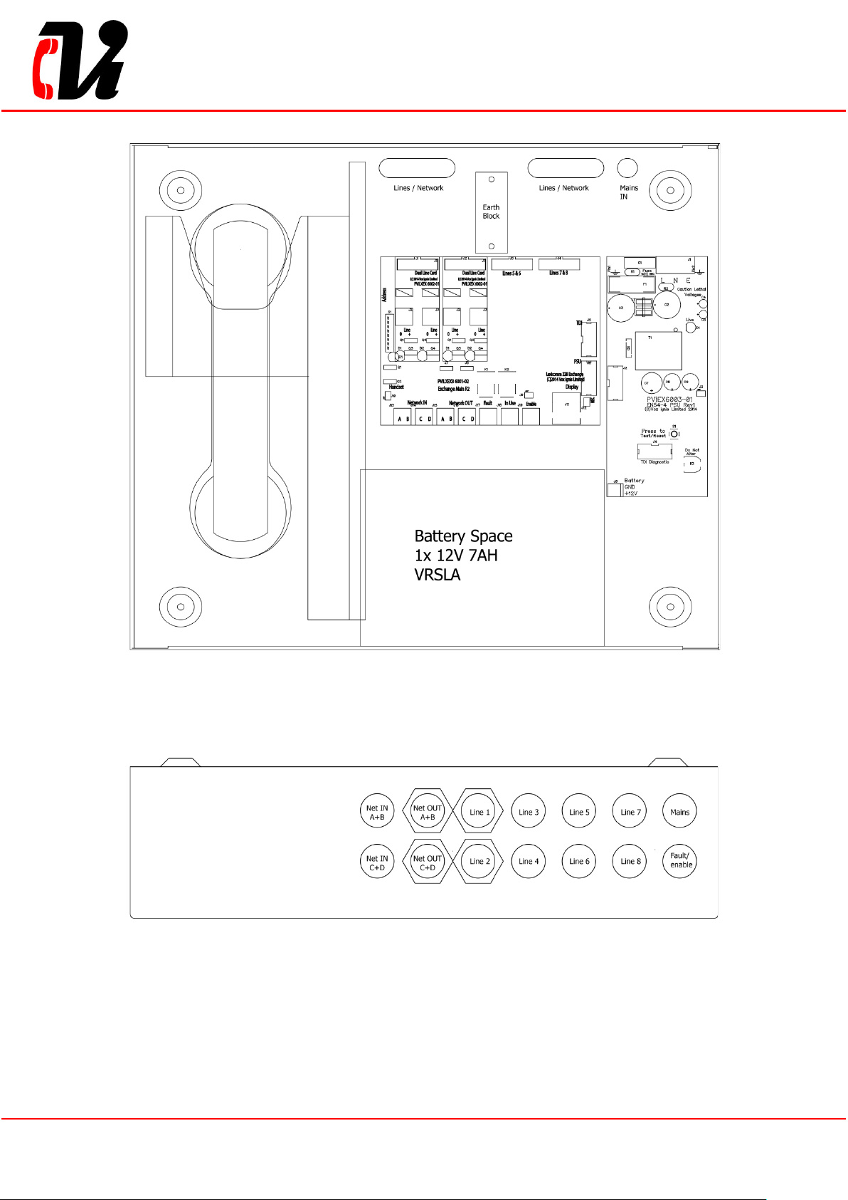
• Correct number of Line Card, depending on configuration. c/w 2 way line connectors.
• 1 number 3 way mains connector.
• 1 number 2 way Fault connector.
• 1 number 2 way In Use connector.
• 1 number 2 way Enable connector.
• 4 number 2 way Network connectors.
• 1 number Batt ery lead.
If there are any items missing, please contact your supplier or Vox Ignis Limited, quoting the unit serial
number and the name on the packing list enclosed, so the situation can be rectified.
Page 5 of 24 Document PViLX228 7001-06 Rev 6 2017
5. Installation
Prior to mounting the ViLX-228 Master Station, it should be decided if the field wiring is to be run on the
surface or concealed. . There are 14 knockouts on the top and 2 slotted entries with a dedicated mains
supply entry at the rear. If a knockout is removed by mistake, fill the hole with a good quality cable
gland.
Unused knockouts must be left unopened to comply with the Low Voltage Directive. Accidentally
knocked out holes should be blanked off.
The ViLX-228 Master Station weighs 6kg with batteries, so care should be taken to securely mount the
Station on stud walling.
Document PViLX228 7001-06 Rev 6 2017 Page 6 of 24
5.1 Connecting the ViLX-228 Master Station
To comply with EMC (Electro Magnetic Compatibility) regulations and to reduce the risk of electrical
interference in the system wiring, the use of fire-resistant screened cables is recommended throughout
the installation.
All wiring should come into the enclosure via the knockouts provided, and be fixed tidily to the relevant
terminals.
Note that correct cable glanding is essential. Due regard should be paid to any system specifications
which demand a certain cable type, providing it meets the appropriate national wiring regulations.
5.2 Planning the Wiring
All system wiring should be installed to meet the appropriate parts of BS5839 Part9:2011 and BS 7671
(Wiring Regulations). Other national standards of installation should be adhered to where applicable.
Do not test wiring using an insulation tester (Megger) with any
equipment connected, as the 500 Volt test voltage will destroy
these devices.
You must observe local wiring regulations. Do not run SELV and LV cables in the same enclosure
without adequate insulation between them.
5.3 Cable and Wiring Guidance
5.3.1 Fire Telephone system
Any system using Type A outstations must use enhanced grade cabling throughout for all wiring,
including the mains supply to the ViLX-228 Master Station.
5.3.2 Disabled Refuge EVC System
For buildings less than 30m in height, or any bui lding with sprinklers fit ted, standard grade f ir e re sistant
cable may be used to wire Type B outstation and the mains supply to the Master Controller; as long as
the planned evacuation will be completed in 30 minutes.
If the building is over 30m in height without sprinklers, or where the evacuation will take place over
multiple stages exceeding 30 minutes, then enhanced grade cables must be used.
5.3.3 Combined Systems
For systems containing Type A, Type B or Type C outstations, shared cable such as network cables
must be enhanced grade.
Cabling to Type A or Type C outstations must be in enhanced grade fire resistant cabling.
Individual spurs to Type B outstations can be wired in standard grade fire resistant cabling in
accordance with the wiring guidelines already set out for disabled refuge systems.
5.3.4 “Assist Call” Emergency Assistance Alarm Systems
All installations must conform to Building Regulations Approved Document M. The “Assist Call ” is wired
using 2 core cable, and the “Assist Call” plates can be wired in any order.
5.4 Cabling methods
There are 3 cabling methods available:
• Connection to a Type A or Type C outstation: use 2 core enhanced grade fire resistant cable
when extending a firefighting telephone system.
• Connection to a Type B outstation: use 2 core standard grade fire resistant cable when
extending a disabl ed refu ge system.
• Connection to an “Assist Call” system on a dedicated line: requires 2 core 1mm CSA or above
PVC sheathed.
Page 7 of 24 Document PViLX228 7001-06 Rev 6 2017
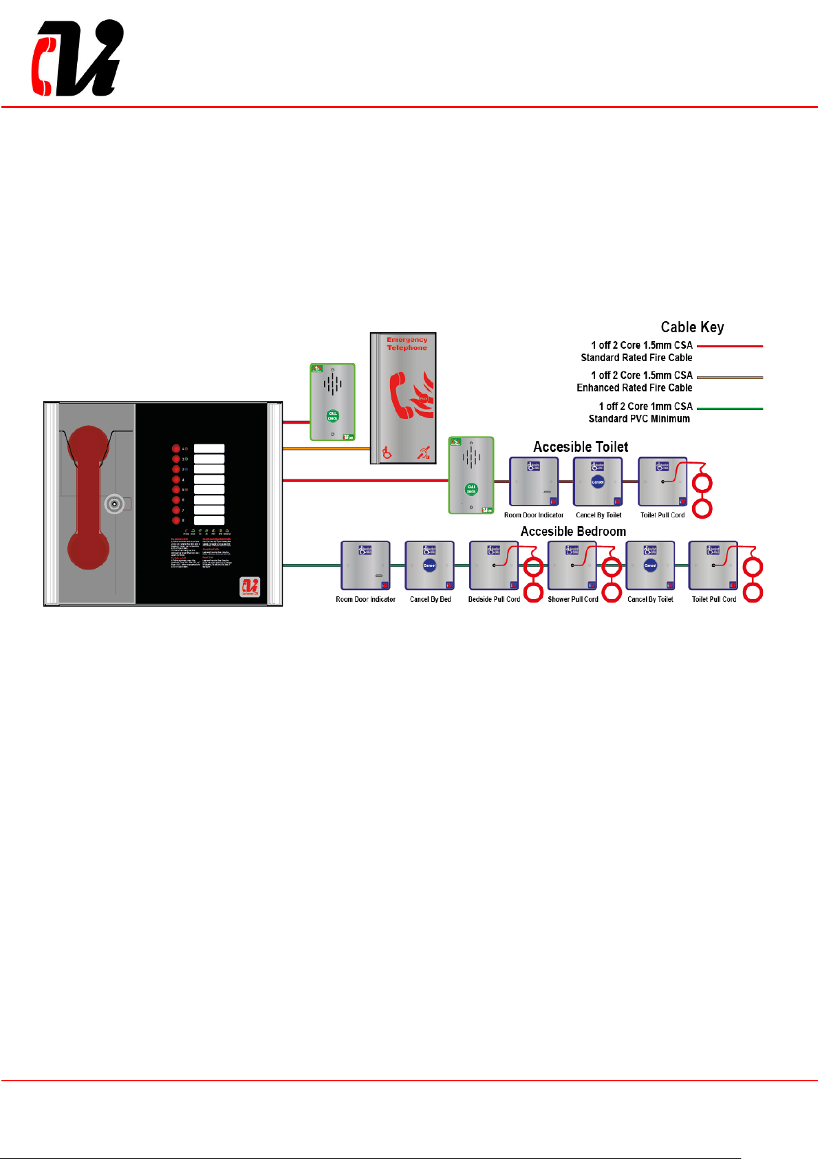
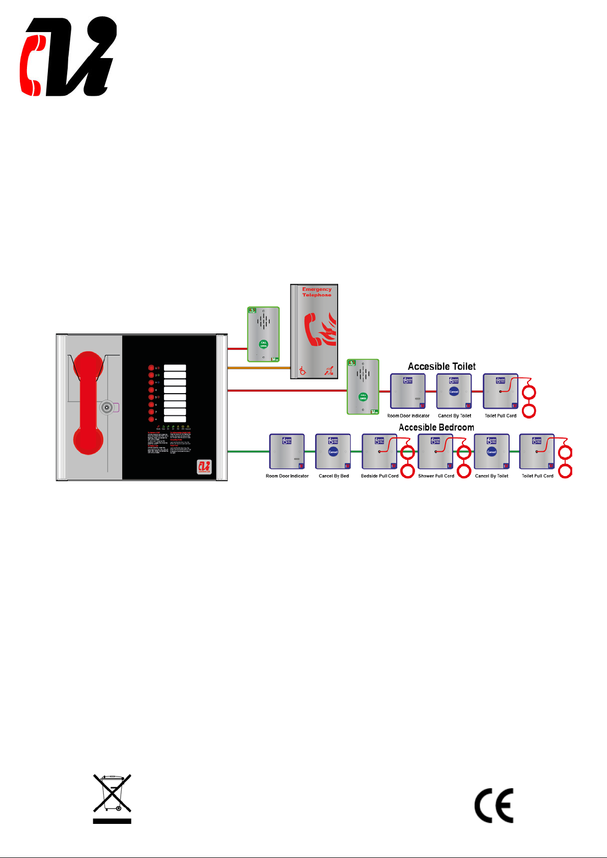
5.4.1 ViLX-228 Master Station Wiring
The wiring for a ViLX-228 Master Station is shown in the schematic below.
Document PViLX228 7001-06 Rev 6 2017 Page 8 of 24
 Loading...