

Lex Computech 2I385HW User Manual

2I385HW
Intel Bay Trail-I E3815 / E3845
(Single Core / Quad Core )CPU,
DDR3L 1066 / 1333 MT/s,
2 x LAN / LVDS / Touch Screen / USB / COM
All-In-One
Intel Bay Trail-I E3815/E3845
(Single Core 1.46 GHz / Quad Core 1.91 GHZ )CPU,
2 x Intel GbE LAN , 2 x PCIe mini card slots ,
VGA, Audio, SATA, USB, COM , LVDS, Touch Screen
NO. 2I385HW_V0.4
Release date: JUN. 30. 2017

Contents
2I385HW
Warning!...........................................................................................................................
Hardware Notice Guide .............................................................................................
CHAPTER 1 GENERAL INFORMATION ........................................................................
1-1 MAJOR FEATURE........................................................................................................
1-2 SPECIFICATION ..........................................................................................................
1-3 INSTALLING THE MINI PCI-E CARD ..........................................................................
1-4 DIRECTIONS FOR INSTALLING THE MINI CARD .....................................................
1-4 PACKING LIST .............................................................................................................
CHAPTER 2 HARDWARE INSTALLATION ....................................................................
2-1 UNPACKING PRECAUTION ........................................................................................
2-2 UNPACKING CHECKUP ..............................................................................................
2-3 DIMENSION-2I385HW ................................................................................................
2-4 LAYOUT-2I385HW-CONNECTOR AND JUMPER .......................................................
2-4-1 LAYOUT-2I385HW-CONNECTOR AND JUMPER BOTTOM ....................................
2-4-2 LAYOUT-2I385HW-FUNCTION MAP .......................................................................
2-4-3 LAYOUT-2I385HW-FUNCTION MAP BOTTOM .......................................................
2-5 DIAGRAM-2I385HW ....................................................................................................
2-5-1 BOTTOM SIDE DIAGRAM-2I385HW .......................................................................
2-6 LIST OF JUMPERS ......................................................................................................
2-7 JUMPER SETTING DESCRIPTION ............................................................................
2-8 JVL1: LCD PANEL POWER SELECT ..........................................................................
CHAPTER 3 CONNECTION ..........................................................................................
3-1 LIST OF CONNECTORS..............................................................................................
3-2 DC POWER INPUT ......................................................................................................
3-3 COMS BATTERY CONNECTOR .................................................................................
3-4 EXTERNAL BATTERY CELL POWER-IN ....................................................................
3-5 DC+12V/+5V VOLTGE POWER OUTPUT (4PIN 2.0MM WAFER) (BLACK)...............
3-6 FRONT PANEL PIN HEADER ......................................................................................
3-7 LVDS CONNECTOR ....................................................................................................
3-8 PANEL INVERTER POWER ........................................................................................
3-9 TOUCH SCREEN DEVICE ..........................................................................................
3-10 AUDIO INTERFACE ...................................................................................................
3-11 AUDIO AMPLIFIER ....................................................................................................
3-12 COM INTERFACE ......................................................................................................
3-13 VGA DISPLAY INTERFACE .......................................................................................
3-14 DIGITAL INPUT/OUTPUT ..........................................................................................
2
3-15 I
C BUS INTERFACE .................................................................................................
3-16 LAN INTERFACE .......................................................................................................
1
2
4
5
6
7
8
9
10
10
11
12
13
14
15
16
17
18
19
19
21
22
22
24
24
25
26
26
27
27
28
29
29
30
31
31
32
33
i

3-17 USB INTERFACE .......................................................................................................
3-18 SATA INTERFACE .....................................................................................................
3-19 PS2 KEYBOARD/MOUSE..........................................................................................
3-20 PCI EXPRESS MINI CARD........................................................................................
3-21 eDP INTERFACE .......................................................................................................
3-22 CONNEXTOR WAFER OF COMPATIBLE BRAND AND PART NUMBER LIST .......
CHAPTER 4 INTRODUCTION OF BIOS ........................................................................
4-1 ENTER SETUP ............................................................................................................
4-2 BIOS MENU SCREEN & FUNCTION KEYS ................................................................
4-3 GETTING HELP ...........................................................................................................
4-4 MENU BARS ................................................................................................................
4-5 MAIN ............................................................................................................................
4-6 ADVANCED ..................................................................................................................
4-6-1 BOOT CONFIGURATION .........................................................................................
4-6-2 PCI EXPRESS CONFIGURATION ...........................................................................
4-6-2-1 PCI EXPRESS ROOT PORT 1/2/3/4 .....................................................................
4-6-3 VIDEO CONFIGURATION ........................................................................................
4-6-4 THERMAL CONFIGURATION ..................................................................................
4-6-5 SATA CONFIGURATION ..........................................................................................
4-6-6 CONSOLE REDIRECTION .......................................................................................
4-6-7 ACPI TABLE/FEATURES CONTROL ........................................................................
4-7 SECURITY ...................................................................................................................
4-8 POWER .......................................................................................................................
4-9 BOOT ...........................................................................................................................
4-9-1 LEGACY ...................................................................................................................
4-9-2 BOOT TYPE ORDER ................................................................................................
4-10 EXIT ...........................................................................................................................
4-11 DEVICE MANAAGER .................................................................................................
4-11-1 SIO FINTEK81801U ................................................................................................
4-11-2 HARDWARE MONITOR ..........................................................................................
4-11-3 SIO FINTEK81216D/DG .........................................................................................
CHAPTER 5 DRIVER INSTALLATION ...........................................................................
5-1 INF INSTALL INTEL BAYTRAIL CHIPSET DRIVER
5-2 VGA INSTALL INTEL BAYTRAIL VGA DRIVER
5-3 SERIAL IO INSTALL DRIVER BAYTRAIL SERIAL IO DRIVER
5-4 XHCI INSTALL INTEL USB 3.0 XHCI DRIVER
(EXAMPLE FOR WIN8 64BIT)
(EXAMPLE FOR WIN8 64BIT)
(FOR WINDOWS 7 ONLY)
(FOR WINDOWS 7 ONLY)
.........................
..............
.....................
5-5 HD AUDIO INSTALL HIGH DEFINITION AUDIO DRIVER ...........................................
5-6 MBI INSTALL INTEL MBI DRIVER
(FOR WIN 8/8.1 ONLY)
.................................................
5-7 TXE INSTALL INTEL TXE DRIVER ..............................................................................
5-7-1 TXE INSTALL FOR WIN8/WIN8.1 ............................................................................
5-7-2 TXE INSTALL FOR WIN7 .........................................................................................
34
35
35
36
37
38
39
39
40
41
42
42
43
44
44
45
46
48
49
50
51
52
53
54
55
55
56
57
58
60
61
63
66
68
70
72
74
75
77
77
79
ii

5-8 HOW TO UPDATE INSYDE BIOS ...............................................................................
APPENDIX A: POWER CONSUMPTION TEST .................................................................
APPENDIX B: RESOLUTION LIST ....................................................................................
APPENDIX C: F75111N I
2
C DIO DEVICE ..........................................................................
1-1 IO DEVICE : F75111 UNDER DOS ..............................................................................
1-2 IO DEVICE : F75111 UNDER WINDOWS ....................................................................
1-3 IO DEVICE : F75111 VB6 UNDER WINDOWS ............................................................
1-4 IO DEVICE : F75111 UNDER LINUX ...........................................................................
81
82
83
84
84
85
88
89
iii

Copyright
This manual is copyrighted and all rights are reserved. It does not allow any non
authorization in copied, photocopied, translated or reproduced to any electronic or
machine readable form in whole or in part without prior written consent from the
manufacturer.
In general, the manufacturer will not be liable for any direct, indirect, special, incidental
or consequential damages arising from the use of inability to use the product or
documentation, even if advised of the possibility of such damages.
The manufacturer keeps the rights in the subject to change the contents of this
manual without prior notices in order to improve the function design, performance,
quality, and reliability. The author assumes no responsibility for any errors or omissions,
which may appear in this manual, nor does it make a commitment to update the
information contained herein.
Trademarks
Intel is a registered trademark of Intel Corporation.
Award is a registered trademark of Award Software, Inc.
All other trademarks, products and or product's name mentioned here are for
identifi cation purposes only, and may be trademarks and/or registered trademarks
of their respective companies or owners.
© Copyright 2014
All Rights Reserved.
User Manual edition 0.1, Dec. 30. 2014

1. Battery
Batteries on board are consumables.
The life time of them are not guaranteed.
2. Fless solution with HDD
The specifi cation & limitation of HDD should be considered carefully when
the fanless solution is implemented.
3. We will not give further notifi cation in case of changes of
product information and manual.
4. SATA interface does not support Hot SWAP function.
5. There might be a 20% inaccuracy of WDT at room temperature.
6. Please make sure the voltage specifi cation meets the requirement
of equipment before plugging in.
7. There are two types of SSD, commercial grade and industrial grade, which
provide different read/write speed performance, operation temperature and
life cycle. Please contact sales for further information before making orders.
8. Caution! Please notice that the heat dissipation problem could cause the MB
system unstable. Please deal with heat dissipation properly when
buying single MB set.
Warning !
9. Please avoid approaching the heat sink area to prevent users from
being scalded with fanless products.
10. If users repair, modify or destroy any component of product unauthorizedly,
We will not take responsibility or provide warranty anymore.
11. DO NOT apply any other material which may reduce cooling
performance onto the thermal pad.
12. It is important to install a system fan toward the CPU to decrease
the possibility of overheating / system hanging up issues,
or customer is suggested to have a fi ne cooling system to dissipate heat
from CPU.
1

Hardware Notice Guide
*
1. Before linking power supply with the motherboard, please attach DC-in adapter to
the motherboard fi rst. Then plug the adapter power to AC outlet.
Always shut down the computer normally before you move the system unit or
remove the power supply from the motherboard. Please unplug the DC-in adapter fi rst
and then unplug the adapter from the AC outlet.
Please refer photo 1 as standard procedures.
2. In case of using DIRECT DC-in (without adapter), please check the allowed range
for voltage & current of cables. And make sure you have the safety protection for
outer issues such as short/broken circuit, overvoltage, surge, lightning strike.
3. In case of using DC-out to an external device, please make sure its voltage and
current comply with the motherboard specifi cation.
4. The total power consumption is determined by various conditions
(CPU/motherboard type, device, application, etc.). Be cautious to the power cable
you use for the system, one with UL standard will be highly recommended.
5. It’s highly possible to burn out the CPU if you change/ modify any parts of
the CPU cooler.
6. Please wear wrist strap and attach it to a metal part of the system unit
before handling a component. You can also touch an object which is
ground connected or attached with metal surface if you don't have wrist strap.
7. Please be careful to handle & don't touch the sharp-pointed components on
the bottom of PCBA.
8. Remove or change any components form the motherboard will VOID the warranty of
the motherboard.
9. Before you install/remove any components or even make any jumper setting
on the motherboard, please make sure to disconnect the power supply fi rst.
(follow the aforementioned instruction guide)
10. "POWERON after PWR-Fair” function must be used carefully as below:
When the DC power adaptor runs out of power, unplug it from the DC current;
Once power returns, plug it back after 5 seconds.
If there is a power outage, unplug it from the AC current, once power returns,
plug it back after 30 seconds. Otherwise it will cause system locked or made
a severe damage.
Remark 1:
Always insert/unplug the DC-in horizontally & directly to/from the motherboard.
DO NOT twist, it is designed to fi t snugly.
Moreover, erratic pull / push action might cause an unpredictable damage to the
component & system unit.
2
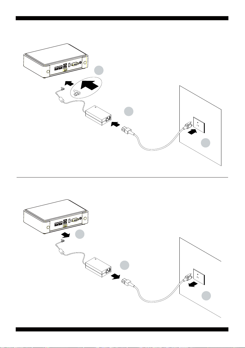
Photo 1 Insert
1
2
3
Unplug
3
2
1
3

Chapter-1
General Information
2I385HW is designed to provide the needs of variety of housing for industrial customers
with all I/O Wafer design board. Unlike LEX’s usual motherboard design,
2I385HW has converted all the onboard I/Os to Wafer connectors in order collocate
industrial customer’s needs. 2I385HW is the perfect platform for whole range of small
form factor and low-power devices.
The 2I385HW All-In-One motherboard is with Intel Intel BayTrail-I E3815 1.46GHz Single
core / E3845 1.91GHz Quad core CPU + Intel BayTrail-I E3815/E3845 chipset and
BayTrail-I Integrated Graphics chipset.
This integrated BayTrail-I platform offers superb performance and PC specification in the
industry. Despite the limited space of 2I385HW, it supports four COM ports and fi ve ports
of USB 2.0 to enhance the host controller interface
which will ensure the high performance level and flexible expansion.
2I385HW is supported with two 10/100/1G Ethernet for seamless broadband connectivity.
With Wake-On LAN function and the PXE function in BIOS, these are perfect control
boards for networking devices.
The built-in LAN is Intel I211-AT or I210-IT (optional) PCIE LAN chipset,
integrated 10/100/1000 transceiver.
The 2I385HW motherboard is built in onboard 2G / 4G DDR3L SDRAM ,
with data transfer rate of 1066MT/s / 1333MT/s. The expendable interfaces include one full
size PCIe Mini card for PCIe by one & mSATA (auto-detection) and USB interfaces,
one half size PCIe Mini card for mSATA and USB interfaces.
The All-In-One motherboard 2I385HW is fully compatible with industry standards,
plus technical enhancements and thousands of software applications developed for
IBM PC/AT compatible computers. These control logic provides high-speed performance
for the most advanced multi user and multitasking applications available today.
4

1-1 Major Feature
1. Intel BayTrail-I E3815 1.46GHz Single core / E3845 1.91GHz Quad core SOC
2. Intel BayTrail-I Integrated Graphics chipset, E3815 400 MHz / E3845 542 MHz
render clock frequency
3. On board DDR3L SDRAM 2GB / 4GB Memory,
data transfer rate of 1066MT/s / 1333MT/s
4. Support 2 x 10/100/1000 Mbps Intel LAN ports
5. Support extended 2 x Mini PCIe card (full size & half size)
6. Support 4 x COM ports and 5 x USB 2.0
7. Support one SATA port with independent DMA operation supported
8. Hardware digital Input & Output, 4 x DI / 4 x DO
Hardware Watch Dog Timer, 0~255 sec programmable
9. On board DC +9V to +36V Wide range power supply
10. PCB Dimension: 102 x 73 mm (2.5 inch)
11. Display interfaces include VGA & LVDS (24/48 bits)
12. COM interface Touch screen controller, support 4-, 5-, 8-
wire Analog Resistive touch screen. Resolution is up to 2048 x 2048
5

1-2 Specifi cation
1. SOC: Intel BayTrail-I E3815 1.46GHz / E3845 1.91GHz (Single / Quad core)
2. Memory: DDR3L SDRAM 2GB / 4GB Memory,
data transfer rate of 1066MT/s / 1333MT/s
3. Graphics: Intel BayTrail-I Integrated Graphics chipset,
E3815 400 MHz / E3845 542 MHz render clock frequency
4. SATA : One SATA connector with independent DMA operation supported
5. LAN: LAN: 2 x INTEL I211-AT / I210-IT (option) PCIE LAN of 10 / 100 / 1000 Mbps
6. Serial Port: 4 x COM ports ( 1 x RS232/422/485 + 3 x RS232/485)
7. USB: 5 x USB 2.0
8. Sound: ALC886 HD Audio Specifi cation 1.0 Two channel sound chipset
9. Audio Amplifi er: TPA2011D1 Class-D 2.5W/4Ω or 1.5W/8Ω chipset
10. WDT/DIO: Hardware digital Input & Output, 4 x DI / 4 x DO
Hardware Watch Dog Timer, 0~255 sec programmable
11. Expansion interface: one full size PCIe Mini card for PCIe/mSATA (auto detection)
and USB interface, one half size PCIe Mini card for mSATA and USB interface
12. BIOS: Insyde UEFI BIOS
13. Dimension: 102 x 73 mm (2.5 inch)
14. Power: On board DC +9V to +36V Wide range power supply
15. LVDS: 24/48 bits
16. Touch function: C8051F321 COM interface Touch screen controller,
support 4-, 5-, 8- wire Analog Resistive touch screen. Resolution is up to 2048 x 2048
6
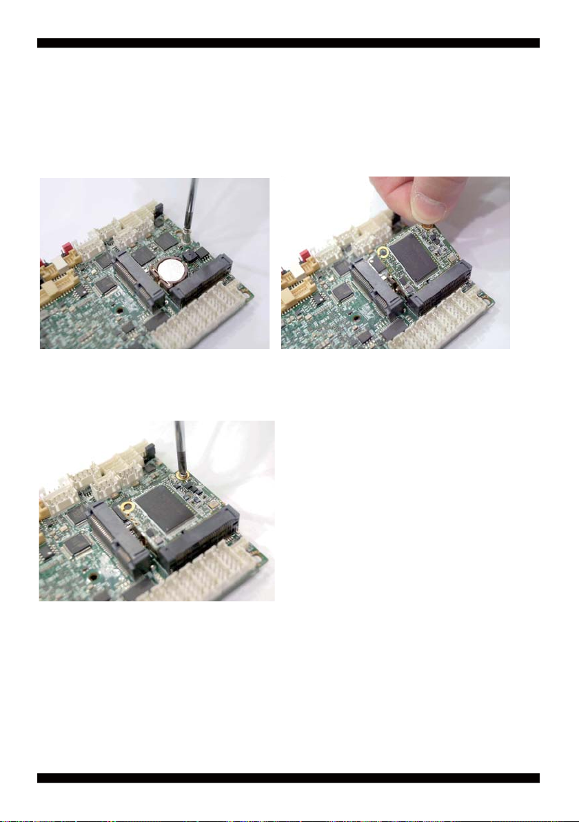
1-3 Installing the Mini PCI-e Card
1. Unfasten the round-headed M2*6
screw for half size Mini PCI-e.
3. Fasten a round-headed M2*6 screw.
2. Install a mSATA card at the angle of 45°.
(The half size Mini PCI-e slot supports mSATA)
7
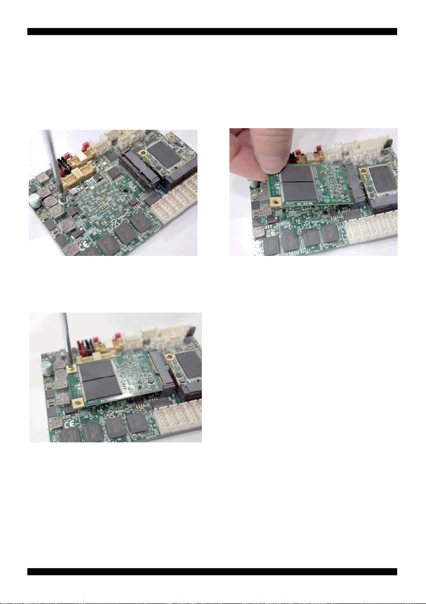
1-4 Directions for installing the Mini Card
1. Unscrew the screw on the board
3. Gently push down the Mini Card and screw the screw back.
2. Plug in the Mini Card in a 45 angle
8
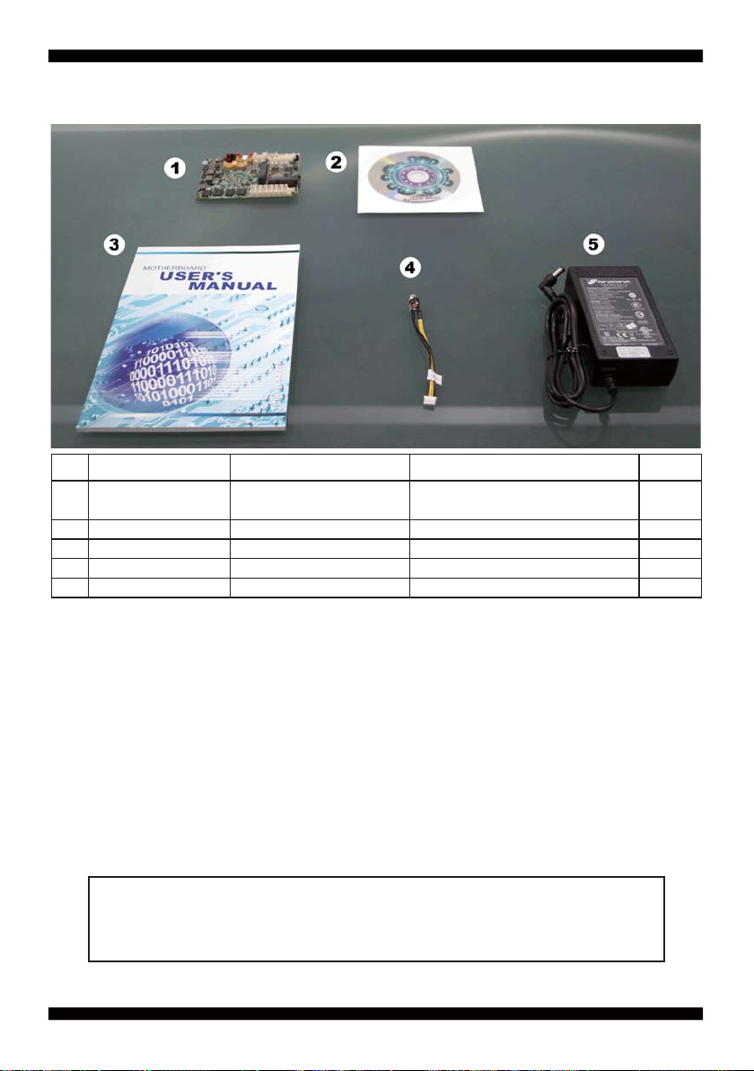
1-5 Packing List
Material Code Description Detail Specifi cation Quantit
7G1901-1530001-0
1
7G1901-1531001-0
6G8006-2347-0100 LEX Product Driver DVD LF, Intel Baytrail Driver 1
2
6G8001-2192-0400 Manual LF,M/B,2I385HW 1
3
6G6003-7330-0100 Power Cable LF,L=9cm,2.0 1*4/DC JK 1
4
6G5212-0301-0300 30W Power Adapter,12V/2.5A LF,L Type,EA10301-M06,EDAC 1
5
MB-2I385HW-I44-001
MB-2I385HW-I12-001
LF,2I385HW-I44,Rev.:001
LF,2I385HW-I12,Rev.:001
1
*The packing list above is for the users who purchase single motherboard. The users
who purchase the board with chassis may refer to the packing list in the Assembly Guide.
Please contact with your dealer if any of these items is missing or damaged
on delivery. And please keep all parts of the delivery package with packing
materials in case if you need to deliver or store the product in the future.
9

Chapter-2
Hardware Installation
2-1 Unpacking Precaution
This chapter provides the information how to install the hardware of 2I385HW.
Please follow section 1-5, 2-1 and 2-2 to check the delivery package and unpack
carefully. Please follow the jumper setting procedure.
NOTE!
1. Do not touch the board or any other sensitive components without all necessary
anti-static protection.
2. Please pay attention to the voltage limitation of DC-IN12 V 5 %.
Overuse of DC-IN voltage limitation or change to another power adapter
( not provided with this system ) will VOID warranty.
You should follow these
steps to protect the board from the static electric
discharge whenever you handle the board:
1. Ground yourself by a grounded wrist strap at all times when you
handle the 2I385HW.
Well secure the ALLIGATOR clip of the strap to the end of the shielded wire lead from
a grounded object. Please put on and connect the strap before handling the
2I385HW for harmlessly discharge any static electricity
through the strap.
2. Please use anti-static pad to put any components, parts, or tools on the pad whenever
you work on them outside the computer. You may also use the anti-static bag instead of
the pad. Please ask your local supplier for necessary parts on anti-static requirement.
3. Do not plug any connector or set any jumper when the power is on.
10

2-2 Unpacking checkup
First of all, please follow all necessary steps of section 2-1 to protect 2I385HW
from electricity discharge. With reference to section 1-5
please check the delivery package again with following steps:
1. Unpack the 2I385HW board and keep all
packing material, manual and driver disc etc, do not dispose !
2. Is there any components lose or drops from the board?
DO NOT CONTINUE TO INSTALL THIS BOARD!
CONTACT THE DEALER YOU PURCHASED
THIS BOARD FROM, IMMEDIATELY.
3. Is there any visible damage on the board?
DO NOT CONTINUE TO INSTALL THIS BOARD!CONTACT
THE DEALER YOU PURCHASED THIS BOARD FROM, IMMEDIATELY.
4. Check your optional parts (i.e. DDR, CF etc.), all necessary jumpers
setting to jumper pin-set, and CMOS setup correctly.
Please also refer to all information of jumper settings in this manual.
5. Check your external devices (i.e. Add-On-Card, Driver Type etc.)
for complete add-in or connection and CMOS setup correctly.
Please also refer to all information of connector connection in this manual.
6. Please keep all necessary manual and driver disc in a good condition for future
re-installation if you change your Operating System.
11
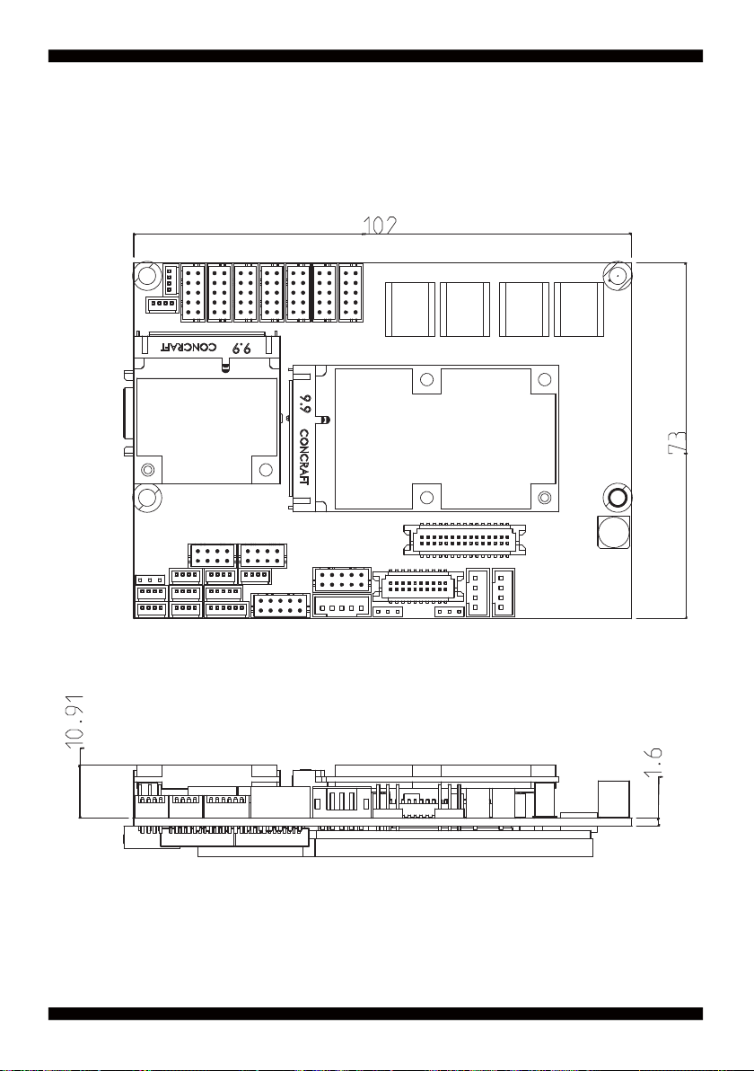
2-3 Dimension-2I385HW
12
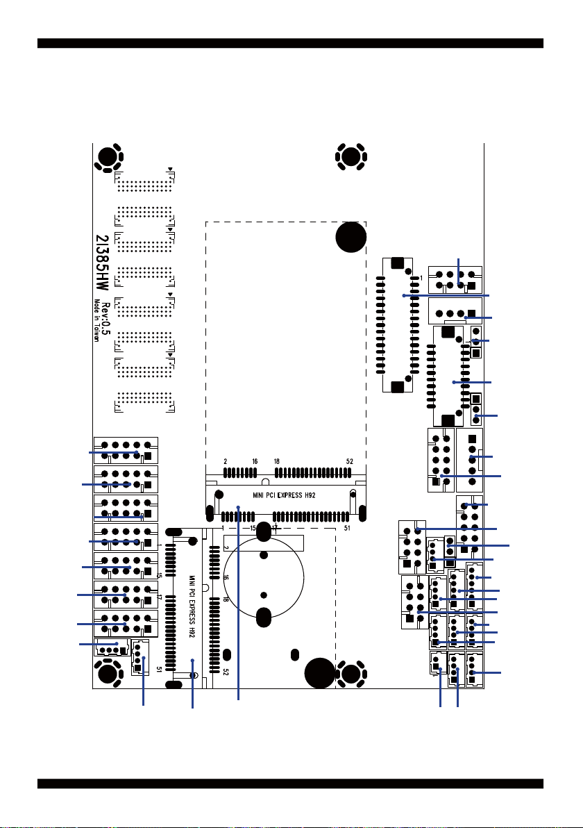
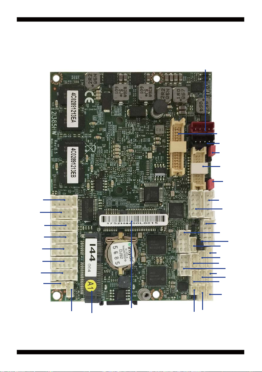
2-4 Layout-2I385HW-Connector and Jumper
CPI1 & CPI2
CPI2 Share with CPI1
LVDS1
CPO1
JVL1
EDP1
JVL2
CC3
CA3
CFP1
CIO1
CO1
CC4
CC2
CC1
CALR1
MPCE2
MPCE1
13
CBT1
CU3
CPP1
CG1
CT1
CL1
CL11
CKM1
CU5
CL21
CL2
CU1
CU2
CU6
CU4
JSB1

2-4-1 Layout-2I385HW-Connector and Jumper Bottom
SATA 1
14
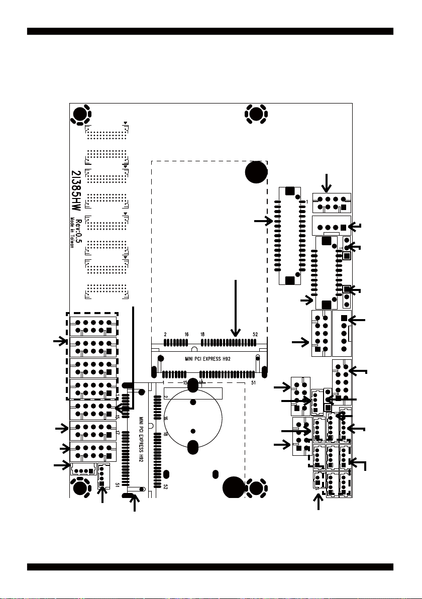
2-4-2 Layout-2I385HW-Function MAP
LVDS 18/24bits
VIN Typical +12V
WV for 9V~36V
Voutage Output
+12V/+5V
COM
ports
Front
Panel
4DI/4DO
I2C
Line-In/Mic-Out/Line-Out
Audio
Amplifi er
PCIe mini card express socket
PCIe / mSATA select one.
defualt is mSATA
2
C
USB / I
PCIe mini card express socket
PCIe / mSATA auto-detec
2
USB / I C
eDP 2Lanes
LAN1
LAN2
LAN1
LED
LAN2
LED
VGA
Panel Power
For LVDS
Panel Power
For eDP
Backlight
Power
Touch
Clear
CMOS
USB 3.0
PS2
KB/MS
USB 2.0
Extermal
Battery cell
15
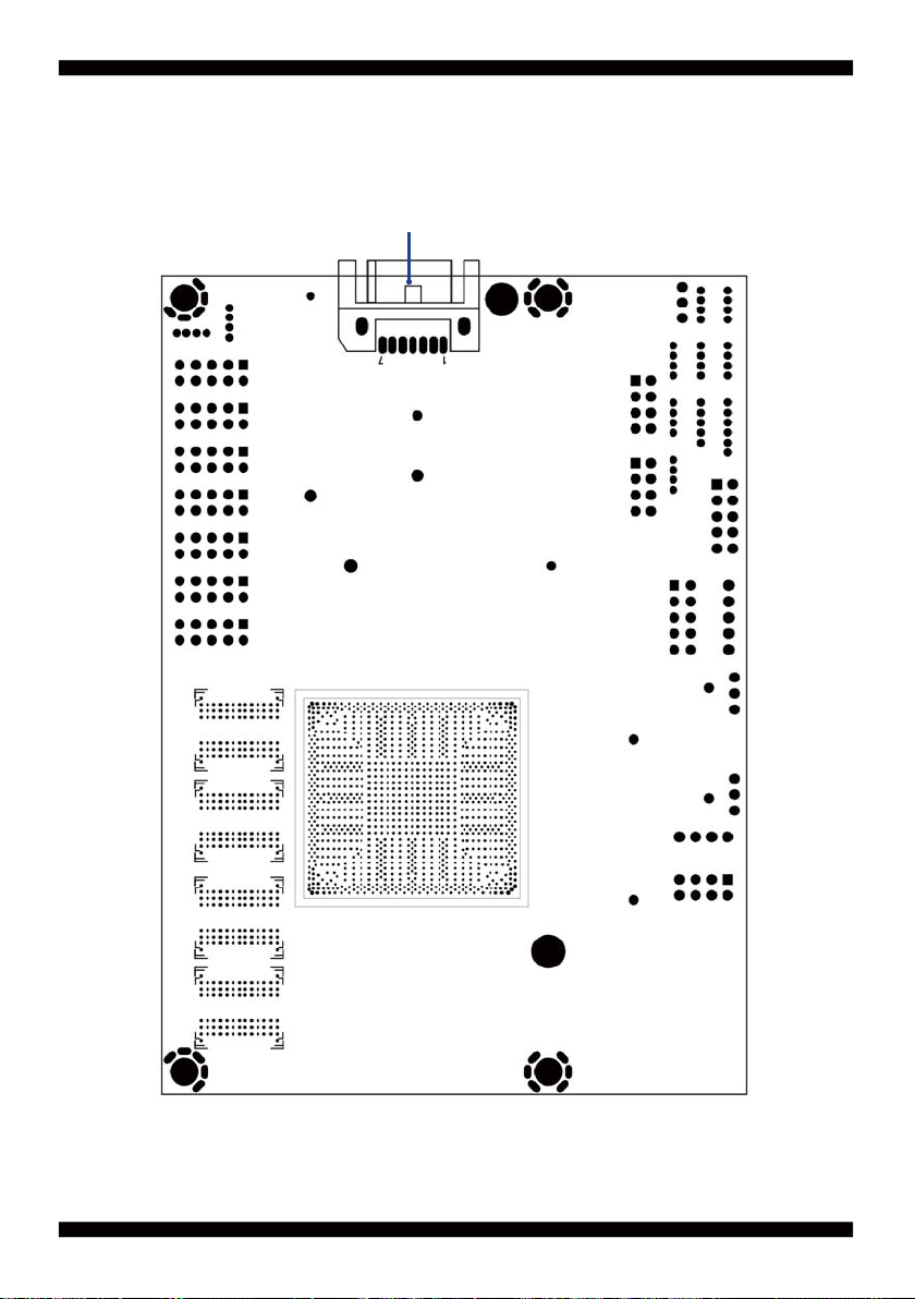
2-4-3 Layout-2I385HW-Function MAP Bottom
SATA
16
2-5 Diagram- 2I385HW
CPI1 & CPI2
CPI2 Share with CPI1
LVDS1
CPO1
JVL1
EDP1
JVL2
CC4
CC3
CC2
CC1
CA3
CFP1
CIO1
CO1
CALR1
MPCE2
MPCE1
17
CBT1
CU3
CPP1
CG1
CT1
CL1
CL11
CKM1
CU5
CL21
CU1
CU6
CU4
JSB1
CL2
CU2
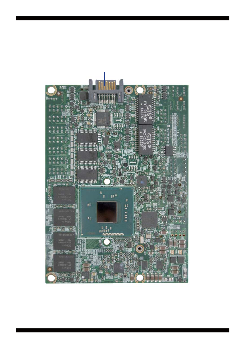
2-5-1 Bottom Side Diagram- 2I385HW
SATA 1
18
2-6 List of Jumpers
JSB1: CMOS DATA Clear
JVL1: LVDS panel power select
JVL2: eDP panel power select
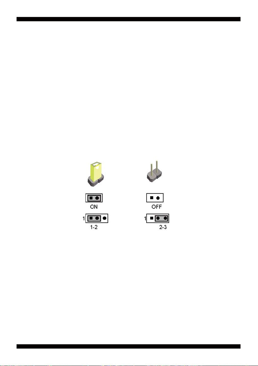
2-7 Jumper Setting Description
A jumper is ON as a closed circuit with a plastic cap covering two pins. A jumper is OFF
as an open circuit without the plastic cap. Some jumpers have three pins, labeled 1, 2,
and 3. You could connect either pin 1 and 2 or 2 and 3.
The below fi gure 2.2 shows the examples of different jumper settings in this manual.
Figure 2.2
All jumpers already have its default setting with the plastic cap inserted as ON,
or without the plastic cap as OFF. The default setting may be referred in this
manual with a " * " symbol .
19
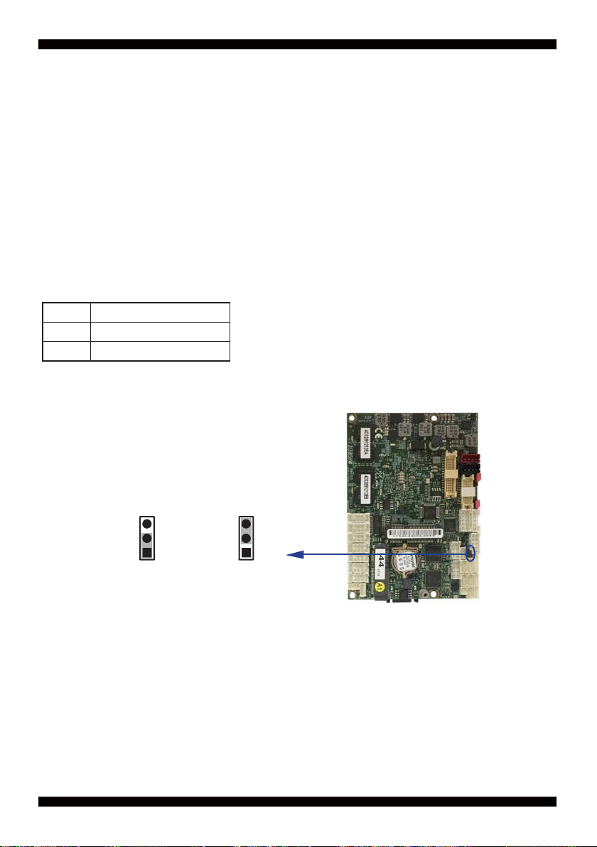
JSB1: CMOS Data Clear
A battery must be used to retain the motherboard confi guration in CMOS RAM.
Close Pin1 and pin 2 of JSB1 to store the CMOS data.
To clear the CMOS,follow the procedures below:
1. Turn off the system and unplug teh AC power
2. Remove DC 12V power cable from DC 12V power connector
3. Locate JSB1 and close pin 1-2 for few seconds
4. Return to default setting by close pin 1-2
5. Connect DC 12V power cable back to DC 12V Power connector
JSB1 Description
*1-2 Normal set
2-3 CMOS data clear
JSB1
*Normal
Note: Do not clear CMOS unless
1. Troubleshooting
2. Forget password
3. You fail over-clocking system
33
22
11
COMS
20
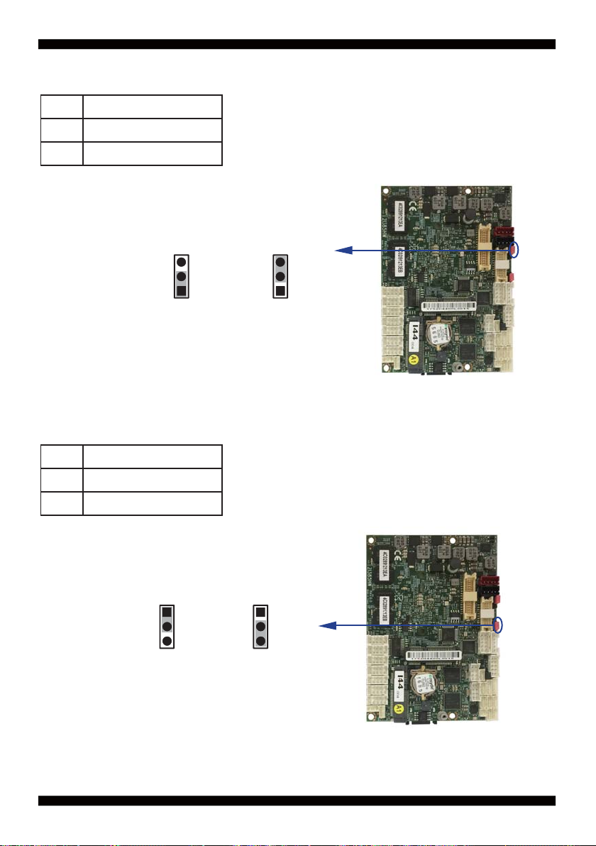
2-8 JVL1: LCD panel power select
JVL1 Description
1-2 +5V
*2-3 +3.3V
Note: Attention! Check Device Power in spec.
JVL1
33
22
11
+5V
*+3.3V
2-9 JVL2: eDP panel power select
JVL2 Description
1-2 +5V
*2-3 +3.3V
Note: Attention! Check Device Power in spec.
JVL2
11
22
33
+5V
*+3.3V
21

Chapter-3
Connection
This chapter provides all necessary information of the peripheral's connections,
switches and indicators. Always power off the board before you install the peripherals.
3-1 List of Connectors
BAT1: Li 3V battery holder
CA3: Line-out/Line-in/Mic-in/SPDIF-out 2x5 pin (2.0mm) Wafer
CALR1: Amplifi er Line-out Right/Left channel 4pin (1.25mm) wafer
CBT1: External Battery 1x2pin (1.25mm) wafer
CC1 : COM 2x5pin (2.0mm) wafer
CC2 : COM 2x5pin (2.0mm) wafer
CC3 : COM 2x5pin (2.0mm) wafer
CC4 : COM 2x5pin (2.0mm) wafer
CFP1: Front Panel connector 2x5pin (2.0mm) wafer
CG1: VGA 2x5pin (2.0mm) wafer
CIO1: DIO 2x5 pin (2.0mm) Wafer
CKM1: PS2 KB/MS 1x6 pin (1.25mm) wafer
CL1: LAN port 1 RJ45 2x4 pin (2.0mm) wafer
CL2 : LAN port 2 RJ45 2x4 pin (2.0mm) wafer
CL11: LAN port 1 LED 1x4 pin (1.25mm) wafer
CL21: LAN port 2 LED 1x4 pin (1.25mm) wafer
2
C 4pin (1.25mm) Wafer
CO1: I
CPI1: DC 12V-IN 1x4 pin (2.0mm) Red wafer connector
CPI12: DC 12V-IN 2x4 pin (2.0mm) wafer connector (Option)
CPP1: Panel inverter power connector 1x5 pin (2.0mm) wafer
CPO1: +12V/+5V power output 4 pin (2.0mm) Black wafer connector
CT1: Touch screen device 2x5 pin (2.0mm) Wafer
CU1: USB 2.0 port 4pin (1.25mm) Wafer
CU2: USB 2.0 port 4pin (1.25mm) Wafer
CU3: USB 2.0 port 4pin (1.25mm) Wafer
CU4: USB 2.0 port 4pin (1.25mm) Wafer
CU5: USB 3.0 port 5pin (1.25mm) Wafer
CU6: USB 2.0 port 4pin (1.25mm) Wafer
22

eDP1: eDP 2x10 pin (1.25mm) connector
LVDS1: LVDS 2x15 pin (1.25mm) connector
SATA1: One SATA connector 7pin
MPCE1: Full size mini card port 1 sockets 52pin
MPCE2: Half size mini card port 2 sockets 52pin
23
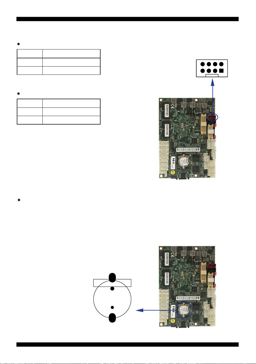
3-2 DC Power Input
CPI1: DC -in 1x4 (2.0mm)Wafer Internal connector (Red)
PIN NO. Description
2,3 DC-IN (12V)
1,4 GND
Note: Very important check DC-in Voltage
CPI12: DC -in 2x4 (2.0mm)Wafer Internal connector
PIN NO. Description
3,4,5,6 DC-IN (12V)
1,2,7,8 GND
Note: Very important check DC-in Voltage
3-3 CMOS Battery connector
BAT1: 3V Battery hold 2pin
BAT1: Battery use Li 3V / 40mAh (CR1220)
Note : 1.When board without Adaptor plug in, this board power
RTC consumption 2.7uA
2.If adaptor always plug in RTC power consumption 0.1uA
CPI1
8
pin1
BAT1
24
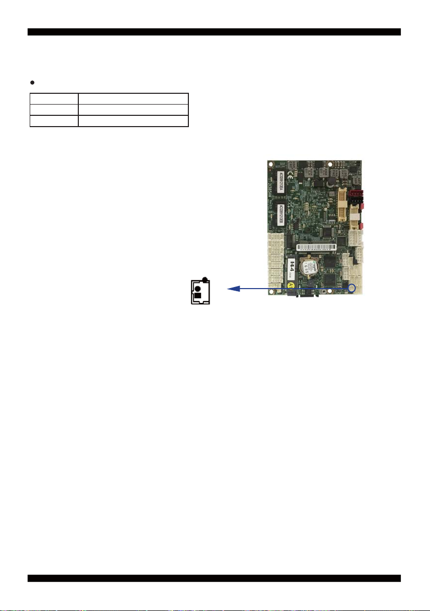
3-4 External Battery Cell Power-in
CBT1: External Battery 1x2pin (1.25mm) wafer
PIN NO. DESCRIPTION
1 GND
2 +3V
CBAT1
pin1
25
 Loading...