

Lex Computech 2I268C User Manual

2I268C
Cedarview-M N2600/N2800 + NM10 / DDR3 800/1066
MHz /DVI / LAN / Audio / USB / PCIe mini card
NO. 2I268C
Release date: August. 22 . 2013
All-In-One
Intel Cedarview-M N2600/N2800, 1.6/1.86GHz
VGA, DVI, LVDS, PCIe mini card
Multi-COM Board, Audio, LAN, SATA, USB

i
Contents
7
9
10
10
11
1
2
4
5
6
12
15
16
14
23
21
17
24
18
25
24
18
16
16
13
26
35
31
35
36
39
36
37
29
38
20
39
40
2I268C
Warning!...........................................................................................................................
Hardware Notice Guide .............................................................................................
CHAPTER 1 GENERAL INFORMATION ........................................................................
1-1 MAJOR FEATURE........................................................................................................
1-2 SPECIFICATION ..........................................................................................................
1-3 INSTALLING THE MINI PCI-E CARD ..........................................................................
1-4 PACKING LIST..............................................................................................................
CHAPTER 2 HARDWARE INSTALLATION ...................................................................
2-1 UNPACKING PRECAUTION .......................................................................................
2-2 UNPACKING CHECKUP .............................................................................................
2-3 DIMENSION-2I268C-DH26 .........................................................................................
2-4 LAYOUT-2I268C-DH26 ................................................................................................
2-5 DIAGRAM-2I268C-DH26 .............................................................................................
2-5-1 BOTTOM SIDE DIAGRAM-2I268C-DH26 ................................................................
2-6 LIST OF JUMPERS .....................................................................................................
2-7 JUMPER SETTING DESCRIPTION ............................................................................
2-8 CMOS DATA SET ........................................................................................................
2-9 JVL1: LCD PANEL POWER SELECT .........................................................................
CHAPTER 3 CONNECTION ........................................................................................
3-1 LIST OF CONNECTORS ...........................................................................................
3-2 AUDIO PORT ..............................................................................................................
3-3 GRAPHIC / VIDEO PORT CONNECTOR ...................................................................
3-4 COM PORTS ...............................................................................................................
3-5 FRONT PANEL CONNECTOR ...................................................................................
3-6 DIGITAL INPUT / OUTPUT / WATCH DOG TIME ......................................................
3-6-1 IO DEVICE: F75111 UNDER DOS ..........................................................................
3-6-2 IO DEVICE: F75111 UNDER WINDOWS ................................................................
3-6-3 IO DEVICE: F75111 VB6 UNDER WINDOWS ........................................................
3-6-4 IO DEVICE: F75111 UNDER LINUX ........................................................................
3-7 TOUCH SCREEN DEVICE .........................................................................................
3-8 I C BUS INTERFACE ..................................................................................................
3-9 DC -IN POWER CONNECTOR ...................................................................................
3-10 CMOS BATTERY CONNECTOR ..............................................................................
3-11 LAN PORT ................................................................................................................
3-12 USB PORTS ..............................................................................................................
3-13 DC+5/+12V VOLTAGE OUTPUT CONNECTOR .....................................................
3-14 SATA INTERFACE ....................................................................................................
3-15 MINI AND SIM CARD ...............................................................................................
2

ii
CHAPTER 4 INTRODUCTION OF BIOS......................................................................
4-1 ENTER SETUP ..........................................................................................................
4-2 GETTING HELP .........................................................................................................
4-3 THE MAIN MENU .......................................................................................................
4-4 STANDARD CMOS FEATURES ................................................................................
4-5 ADVANCED BIOS FEATURES ..................................................................................
4-5-1 HARD DISK BOOT PRIORITY ................................................................................
4-5-2 USB BOOT PRIORITY ............................................................................................
4-6 ADVANCED CHIPSET FEATURES ...........................................................................
4-6-1 PCI EXPRESS ROOT PORT FUNC .......................................................................
4-7 INTEGRATED PERIPHERALS ..................................................................................
4-7-1 OnCHIP IDE DEVICE ............................................................................................
4-7-2 SUPER IO DEVICE .................................................................................................
4-7-3 USB DEVICE FUNCTION .......................................................................................
4-8 POWER MANAGEMENT SETUP ..............................................................................
4-8-1 PCI EXPRESS PM FUNCTION ...............................................................................
4-9 PNP/PCI CONFIGURATION SETUP .........................................................................
4-9-1 IRQ RESOURCES ...................................................................................................
4-10 PC HEALTH STATUS ................................................................................................
4-11 LOAD OPTIMIZED DEFAULTS ................................................................................
4-12 SET SUPERVISOR / USER PASSWORD ...............................................................
CHAPTER 5 DRIVER INSTALLATION........................................................................
5-1 INF INSTALL INTEL CEDARVIEW CHIPSET DRIVER ..............................................
5-2 VGA INSTALL INTEL CEDARVIEW VGA DRIVER ....................................................
5-3 SOUND INSTALL VIA HD AUDIO CODEC DRIVER ..................................................
5-4 HOW TO UPDATE BIOS ............................................................................................
APPENDIX A: POWER CONSUMPTION TEST................................................................
APPENDIX B: RESOLUTION LIST ..................................................................................
42
49
41
41
42
45
44
47
50
48
52
47
53
51
50
65
59
61
67
68
69
55
56
55
68
63
57
57

Copyright
Trademarks
This manual is copyrighted and all rights are reserved. It does not allow any non
authorization in copied, photocopied, translated or reproduced to any electronic or
machine readable form in whole or in part without prior written consent from the
manufacturer.
In general, the manufacturer will not be liable for any direct, indirect, special, incidental
or consequential damages arising from the use of inability to use the product or
documentation, even if advised of the possibility of such damages.
The manufacturer keeps the rights in the subject to change the contents of this
manual without prior notices in order to improve the function design, performance,
quality, and reliability. The author assumes no responsibility for any errors or omissions,
which may appear in this manual, nor does it make a commitment to update the
information contained herein.
Intel is a registered trademark of Intel Corporation.
Award is a registered trademark of Award Software, Inc.
All other trademarks, products and or product's name mentioned here are for
identification purposes only, and may be trademarks and/or registered trademarks
of their respective companies or owners.
c Copyright 2013
All Rights Reserved.
User Manual edition 0.1,August .22. 2013

1
1. Battery
Battery on board is consumables. We doesn’t guarantee the life time of it.
2. Fanless solution with HDD
Please be aware of specification & limitation for HDD when fanless solution
is implemented.
3. We will not give further notification if there is any change about the product
information and the manual.
4. SATA does not support Hot SWAP.
5. There would be 20% difference of WDT at room temperature.
6. Please make sure the voltage specification meet the requirement
of the equipment before plugging into the power.
7. SSD has 2 types, commercial grade and industrial grade, which provide
different read/write speed, operation temperature and life cycle.
Please contact sales for further information before ordering.
8. Caution ! Please notice that the heat dissipation problem could cause the
MB system unstable. Please handle the heat dissipation properly when
buying single MB.
9. Please avoid to approach the heat sink area and prevent being scalded when
using the Fanless products.
10. If the users repair, modify or destroy any component of product
unauthorized, We would not take responsibility or provide warranty.
11. DO NOT apply any other material onto the thermal pad in case reducing
cooling performance.
12. It is important to install a System Fan toward the CPU to prevent the
possibility of overheating / system hang up issues from Cedar view-D series
of motherboard or else customer is required to have well cooling system to
dissipate heat from CPU.
Warning !
+
-

2
Hardware Notice Guide
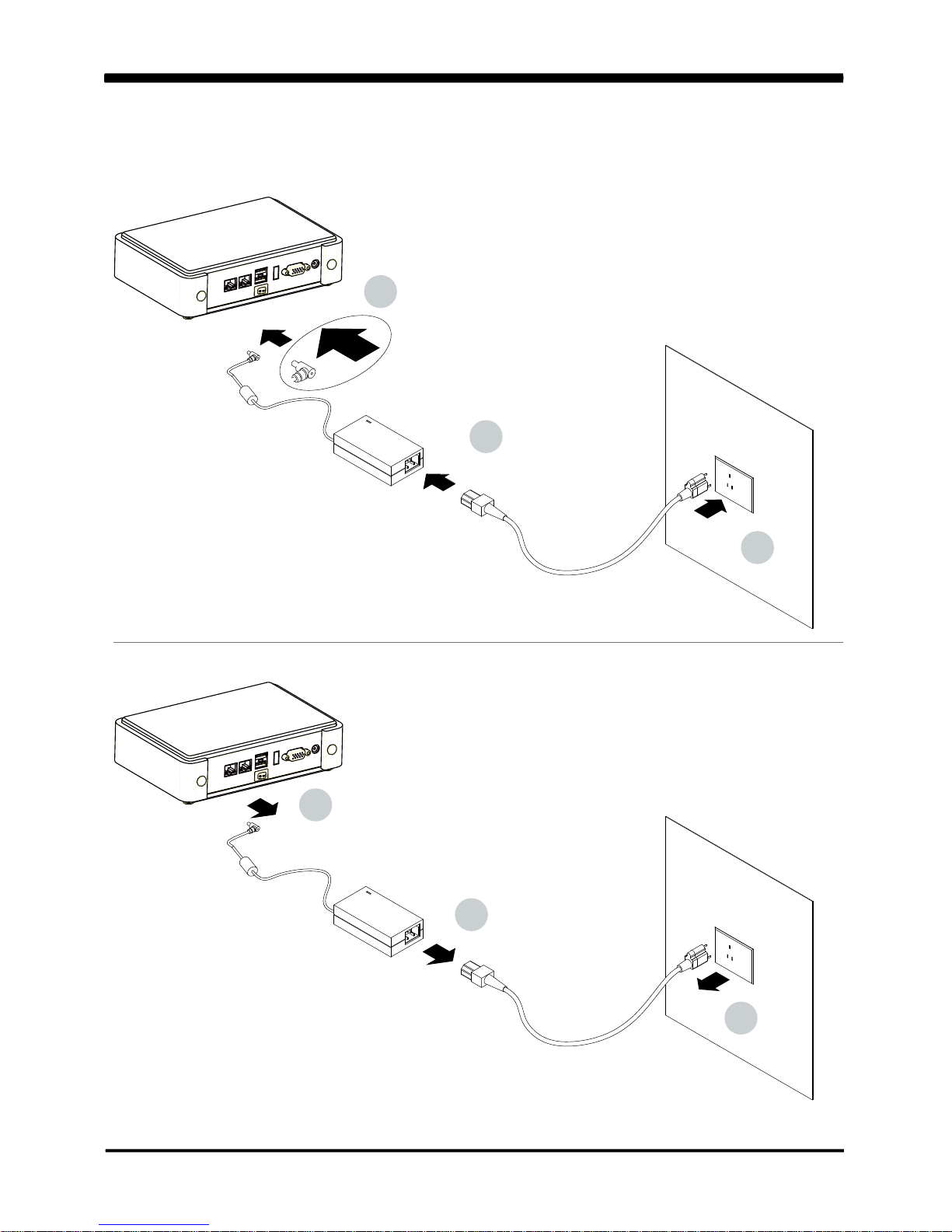
1. Before installing the power supply with this motherboard, please attach the 12V/DC
( 2 pin connector )of the adapter to motherboard first.
After that, plug the adapter power to AC outlet.
Always normally shut down the computer before you move the system unit or remove
the power supply from the motherboard.
Please unplug the 12V/DC ( 2 pin connector ) of the adapter from motherboard first.
Then unplug the adapter from the AC outlet.
Please refer to procedure from the photo 1
2. There will be high possibility to burn out the CPU if you change/ modify any parts of the
CPU cooler.
3. Please wear wrist strap and attach it to a metal part of the system unit before handling a
component.
You can also touch an object that is of ground connection or with metal surface if you don't
have wrist strap.
4. Please be careful when you handle this product. Pay attention to & don't touch the
sharp-pointed components at the bottom PCB .
5. Please pay attention to this: Remove or change any components form the motherboard
will VOID the warranty of the motherboard you purchased .
6. Before you install/remove any components or make any jumper setting on the motherboard,
please make sure to disconnect the power first.
( Please follow the instructions as of this guide )
7. Please only use single side Mini PCIe card, do not use the double side Mini PCIe card
which is not suitable.
8. Please follow this instruction carefully when using the "POWERON after PWR-Fair" function.
When the DC power adaptor runs out of power, unplug it from the DC current;
when power returns plug it back in only after 5 seconds. If there is a power outage,
unplug it from the AC current, when power returns plug it back in only after 30 seconds.
Otherwise it will cause system locking or serious damage.
Remark 1:
Always insert/unplug the 12V/DC ( 2 pin connector ) horizontally & directly from the
motherboard.
DO NOT twist the 12V/DC ( 2 pin connector ) gently, it is designed to fit snugly .
Moreover, erratic pull / push testing with the DC Jack might cause the unpredictable
damage to the component & system unit.
*
3
Photo 1
2
1
3
1
2
3
Insert
Unplug

4
The 2I268C is a 2.5 inches form factor All-In-One Board. The board design combines
all necessary input and output effects interfaces, which makes itself an ideal all-in-one
control board for POS, Digital Signage and Automation application. Due to its compact size,
2I268C is also the perfect platform for a whole range of small form factor and low-power
devices, such as mobile PC or small panel PC
The 2I268C All-In-One motherboard is with Intel Cedar view-M N2600 1.6GHz /
N2800 1.86GHz CPU (Dual core processor), Intel Cedarview-M + NM10 chipset and Intel
Cedar view-M Integrated Graphics chipset. This integrated Cedar View platform offers
superb performance and PC specification in the industry. Despite the limited space of 2I268C,
it supports 2 COM ports of RS232(or RS485) and 5 ports of Hi-Speed USB 2.0 to enhance
the host controller interface which will ensure the high performance level
and flexible expansion.
2I268C is supported with one 10/100/1G Ethernet for seamless broadband
connectivity. With Wake-On LAN function and the PXE function in BIOS,
these are perfect control boards for networking devices. The built-in Lan is RTL8111F LAN
chipset for PCIe x 1 interface, integrated 10/100/1000 transceiver.
The 2I268C motherboard is built in on board DDR3 SDRAM 2GB,
N2600 / N2800 Memory DDR3 data transfer rate of 800MT/s / 1066MT/s and optional with
On board SATA SSD 2/4/8/16/32/64---GBytes. The expendable interfaces include one full
size PCIe Mini card for PCIe by one and USB interface, one half size PCIe Mini card
for mSATA and USB interface.
The All-In-One motherboard 2I268C is fully compatible with industry standards,
plus technical enhancements and thousands of software applications developed for
IBM PC/AT compatible computers. These control logic provides high-speed performance
for the most advanced multi user and multitasking applications available today.
Chapter-1
General lnformation

5
1. Intel Cedarview-M N2600 1.6GHz CPU / N2800 1.86GHz CPU
2. Intel Cedarview-M and NM10 chipset on board
3. Intel Cedarview-M Integrated Graphics chipset, N2600 400 MHz or N2800 640 MHz
render clock frequency. Support Directx* 10.1 compliant Pixel Shader* v2.0 and OGL 3.0
4. On board DDR3 SDRAM 2GB, N2600 / N2800 Memory DDR3 data transfer rate
of 800MT/s / 1066MT/s.
5. On board SSD 2/4/8/16/32/64 GBytes (Option)
6. Support 1 x 10 / 100 / 1000 Mbps Realtek LAN
7. Support extended 2 x Mini PCIe card ( full size & half size)
8. One SATA port with independent DMA operation supported
9. 1 x DVI support resolution up to 1920 x 1200
10. Hardware digital Input & Output, 4 x DI / 4 x DO
Hardware Watch Dog Timer, 0~255 sec programmable
11. On board DC +12V
12. PCB Dimension: 102 x 73 mm (2.5 inch)
13. One 3G SIM card socket (Option)
14. USB /COM interface Touch screen controller, support 4- , 5- , 8- wire Analog
Resistive touch screen. Resolution is up to 2048 x 2048.
1-1 Major Feature

6
1. CPU: Intel Cedarview-M N2600 / N2800
2. Chipset: Intel Cedarview-M and NM10
3. Memory: DDR3 SDRAM 2GB, N2600 / N2800 Memory DDR3 data transfer rate
of 800MT/s / 1066MT/s.
4. SATA: One SATA port with independent DMA operation supported
5. NAND flash memory (Option):
On board SATA SSD 2/4/8/16/32/64---GBytes (Option)
6. LAN: 1 x Realtek RTL8111F 10 / 100 / 1000 Mbps
7. Serial Port: External x 1 optional with Line out & 2 x USB;
internal x 1 share with Audio AMP
8. USB: 5 x USB 2.0 (2 external + 3 internal)
9. Sound: Intel High Definition Audio Specification Rev.1.0 Compliant
10. Audio Amplifier: Two channel Class D Audio Amplifier. 2.57W/Ch (Typ.) into a 4ΩLoad;
1.46 W/Ch (Typ.) into a 8ΩLoad (Option)
11. WDT/DIO: Hardware digital Input & Output, 4 x DI / 4 x DO /
Hardware Watch Dog Timer, 0~255 sec programmable
12. Expansion interface: One full size PCIe Mini card for PCIe by one and USB interface;
One half size PCIe Mini card for mSATA and USB interface
13. BIOS: Award BIOS Version
14. Dimension: 102 x 73 mm (2.5 inch)
15. Power: On board DC +12V
16. Power Consumption: Please refer to Page. 68
17. 3G Wireless: 3G SIM card reader (Option)
18. LVDS: 18 bits LVDS
19. Touch function: USB /COM interface Touch screen controller, support 4- , 5- , 8-
wire Analog Resistive touch screen. Resolution is up to 2048 x 2048 (option)
1-2 Specification
7
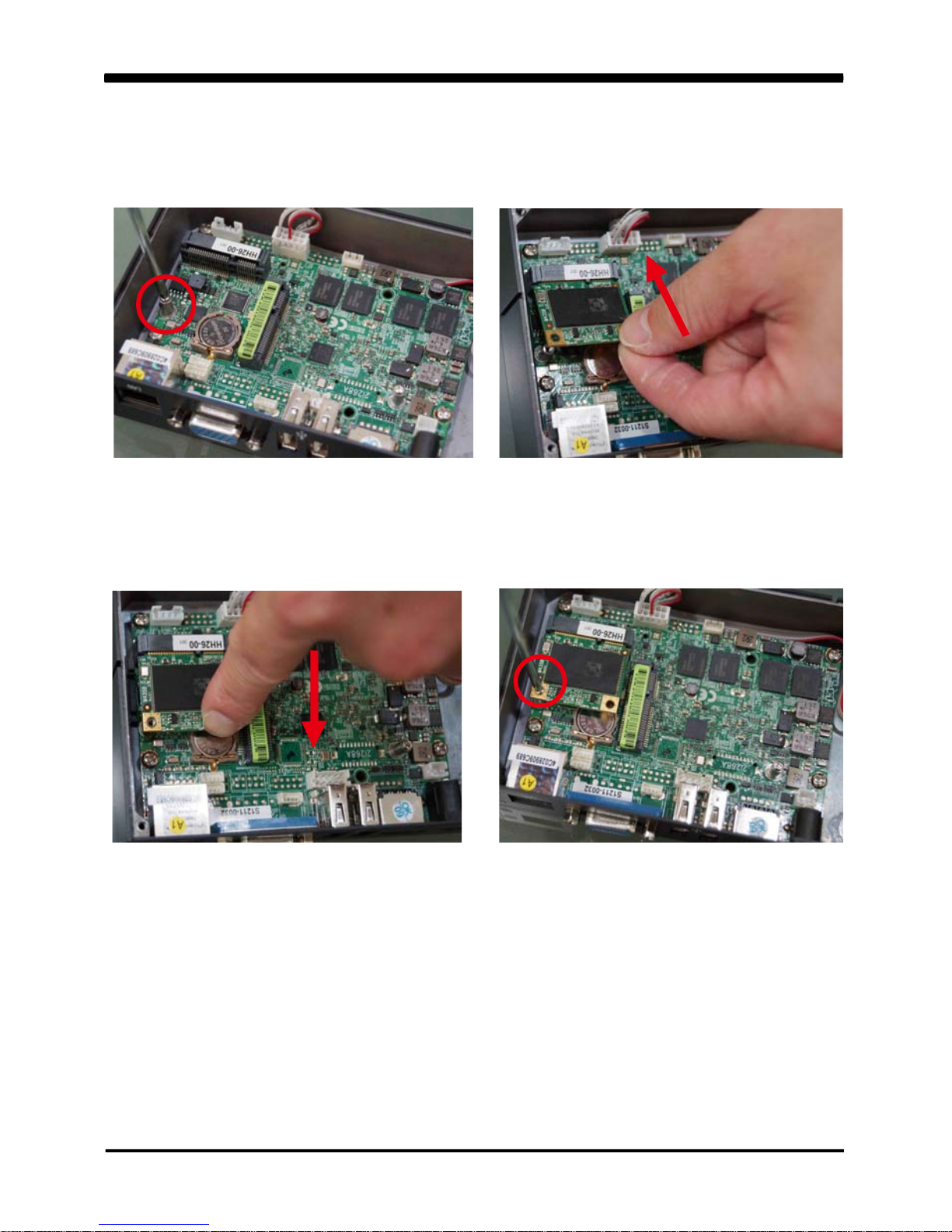
1-3 Installing the MINI PCI-E Card
1. Unfasten the round-headed M2*6
screw for half size MINI PCI-E.
2. Install a mSATA card at the angle of 45°.
(The half size MIIN PCI-E slot supports mSATA)
3. Push it down.
4. Fasten a round-headed M2*6 screw.
8
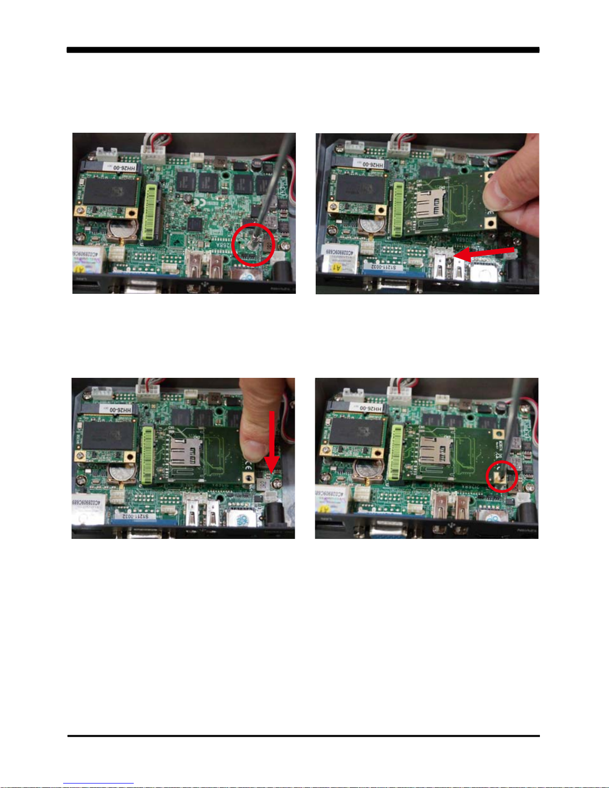
5. Unfasten the round-headed M2*6 screw
for the full size MINI PCI-E.
6. Install the full size MINI PCI-E card at the
angle of 45°.
(Such as 3G card module, Wireless card
module or GPS card module)
7. Push it down.
8. Fasten round-headed M2*6 screw.
9
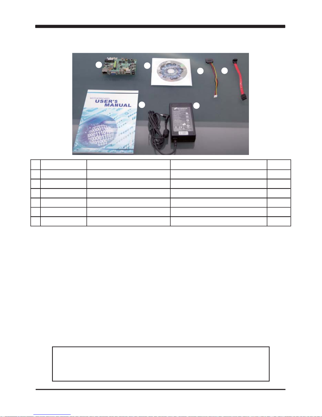
1-4 Packing List
Please contact with your dealer if any of these items is missing or damaged
on delivery. And please keep all parts of the delivery package with packing
materials in case if you need to deliver or store the product in the future.
*The packing list above is for the users who purchase single motherboard. The users
who purchase the board with chassis may refer to the packing list in the Assembly Guide.
1
2
3
4
5
6
Material Code Description Detail Specification Quantit
1
1
1
1
1
1
7G1901-1251001-0 MB-2I268C-DH26-00-001 LF ,2I268C-DH26-00,Rev .:001
6G8006-2344-0100 DVD LF ,Intel Cedarview-M/D,Sandy Bridge
6G6003-1006-0100 SA T A Power Cable LF ,L=15cm,SA T A to 2.0/1*4
6G6001-2208-0100 SA T A DA T A Cable,(Red) LF ,L=15cm
6G8001-2175-0400 Manual LF ,M/B,2I268C
6G5212-0301-0300 30W Power Adapter ,12V/2.5A LF ,L T ype,EA10301-M06,EDAC
1
2
3
5
6
4

10
Hardware Installation
This chapter provides the information how to install the hardware of 2I268C .
Please follow section 1-4, 2-1 and 2-2 to check the delivery package and unpack
carefully. Please follow the jumper setting procedure.
Chapter-2
2-1 Unpacking Precaution
The 2I268C board has been well packed with an anti-static bag to protect its sensitive
components and circuitry from damage due to static electric discharge.
You should follow these
steps to protect the board from the static electric
discharge whenever you handle the board:
1. Ground yourself by a grounded wrist strap at all times when you handle the 2I268C.
Well secure the ALLIGATOR clip of the strap to the end of the shielded wire lead from
a grounded object. Please put on and connect the strap before handling the
2I268C for harmlessly discharge any static electricity through the strap.
2. Please use anti-static pad to put any components, parts, or tools on the pad whenever
you work on them outside the computer. You may also use the anti-static bag instead of
the pad. Please ask your local supplier for necessary parts on anti-static requirement.
3. Do not plug any connector or set any jumper when the power is on.
1. Do not touch the board or any other sensitive components without all necessary
anti-static protection.
2. Please pay attention to the voltage limitation of DC-IN12 V 5 %.
Overuse of DC-IN voltage limitation or change to another power adapter
( not provided with this system ) will VOID warranty.
NOTE!
+
-

11
2-2 Unpacking checkup
First of all, please follow all necessary steps of section 2-1 to protect 2I268C
from electricity discharge. With reference to section 1-4
please check the delivery package again with following steps:
1. Unpack the 2I268C board and keep all packing material,
manual and driver disc etc, do not dispose !
2. Is there any components lose or drops from the board? DO NOT CONTINUE
TO INSTALL THIS BOARD! CONTACT THE DEALER YOU PURCHASED THIS
BOARD FROM, IMMEDIATELY.
3. Is there any visible damage on the board? DO NOT CONTINUE TO INSTALL
THIS BOARD!CONTACT THE DEALER YOU PURCHASED THIS
BOARD FROM, IMMEDIATELY.
4. Check your optional parts (i.e. DDR, CF etc.), all necessary jumpers
setting to jumper pin-set, and CMOS setup correctly.
Please also refer to all information of jumper settings in this manual.
5. Check your external devices (i.e. Add-On-Card, Driver Type etc.)
for complete add-in or connection and CMOS setup correctly.
Please also refer to all information of connector connection in this manual.
6. Please keep all necessary manual and driver disc in a good condition for future
re-installation if you change your Operating System.
12
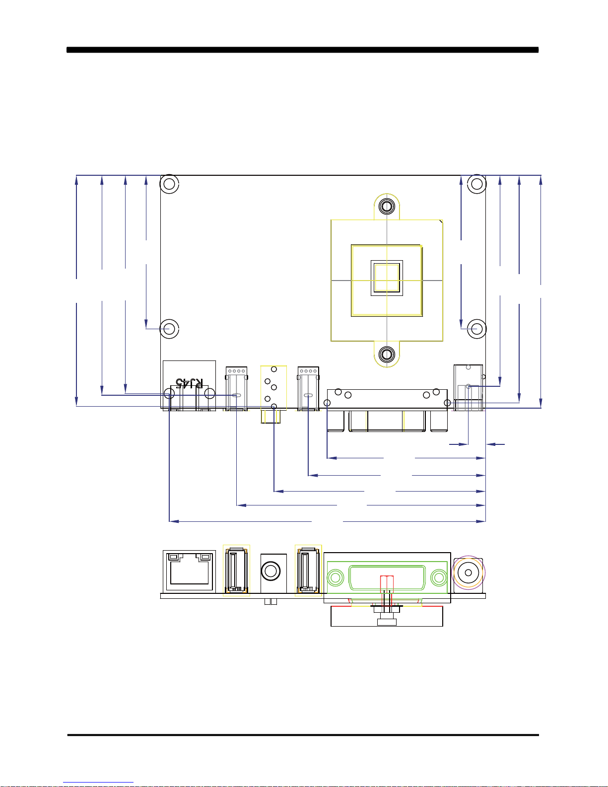
2-3 Dimension - 2I268C - DH26
2I268C-DH26
5.44
49.75
55.64
78.14
48.2
68.44
68.99
71.37
66.19
73
66.42
99.25
72.5
48.2
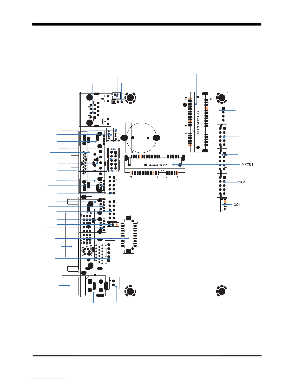
2-4
Layout- 2I268C-DH26
13
CPI11
DVI1
CPP1
CU11
CU1
CU2
CU4
JVL1
CG11
CA3
CU21
CU3
CA1
CG1
CL1
CBT1
JSB1
CU31
CU41
CAL1
CAR1
CU5
CC2
LVDS1
CPI1 CPI12
MPCE2
CPO1
CT1
CFP1
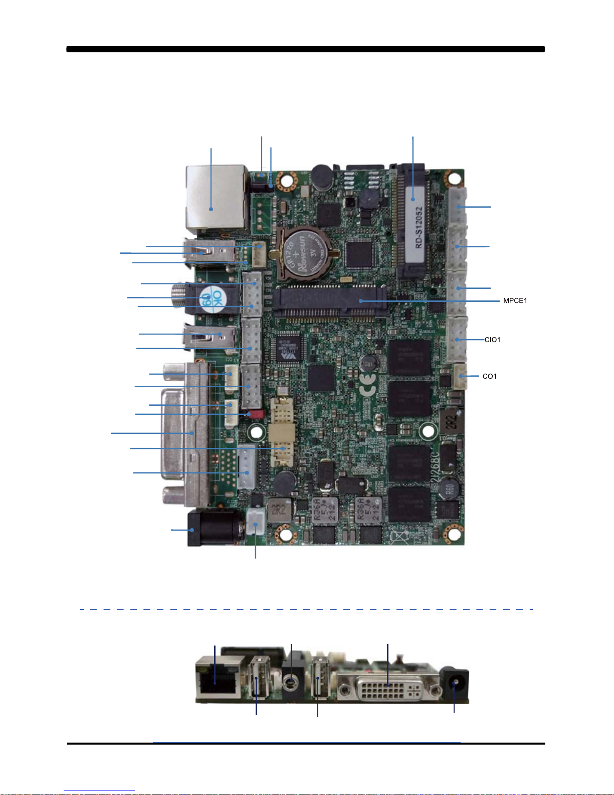
2-5 Diagram- 2I268C-DH26
Back Panel
Line out
DC 12V IN
DVI
USB
LAN1
USB
CPI1
CPP1
DVI1
CU21
CU11
CU4
JVL1
CG11
CA3
CA1
CL1
CBT1
JSB1
CU41
CAL1
CAR1
CU5
CU3
LVDS1
CPI12
MPCE2
CPO1
CT1
CFP1
14
15
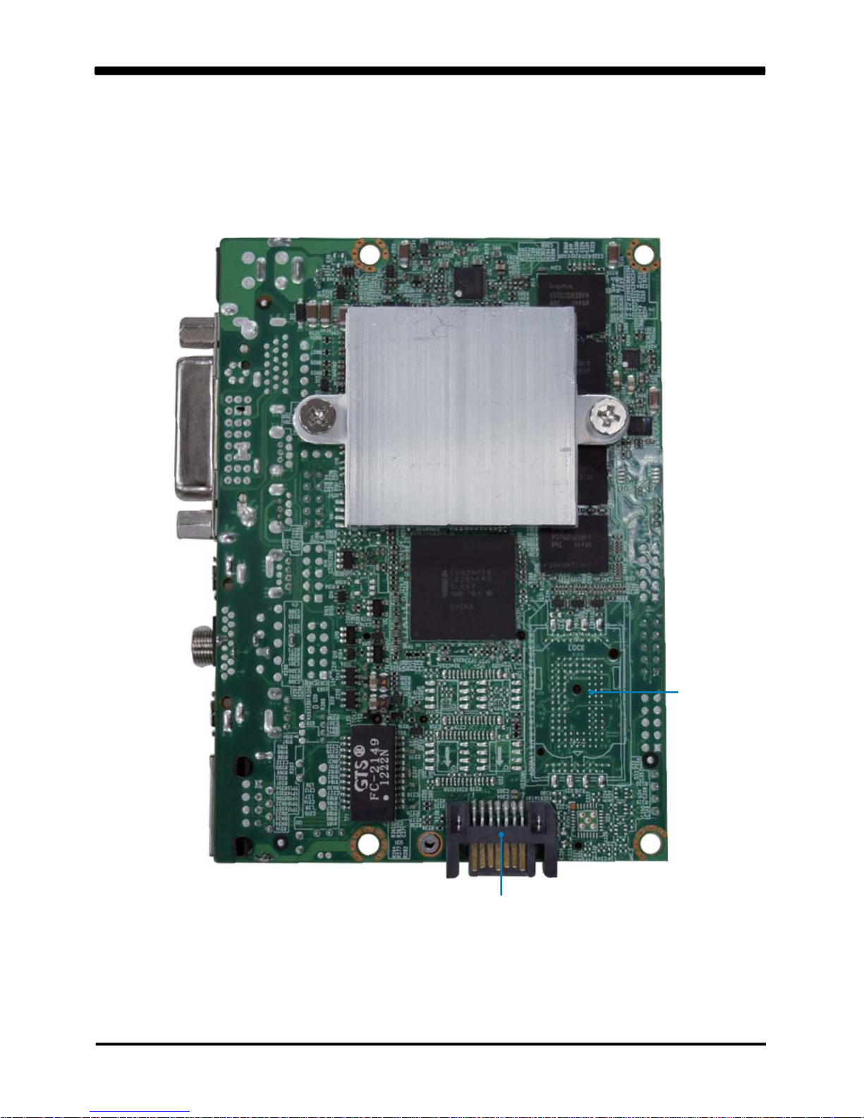
2-5-2 Bottom Side Diagram-2I268C-DH26
SATA1
SIM1
16
2-8 CMOS Data Set
A battery must be used to retain the motherboard configuration in CMOS RAM.
Close pin 1and pin 2 of JSB1 to store the CMOS data.
To clear the CMOS, follow the procedures below:
1. Turn off the system and unplug the AC power
2. Remove DC 12V power cable from DC 12V power connector
3. Locate JSB1 and close pin 2-3 for a few seconds
4. Return to its normal setting by shorting pin 1-2
5. Connect DC 12V power cable back to DC 12V power connector
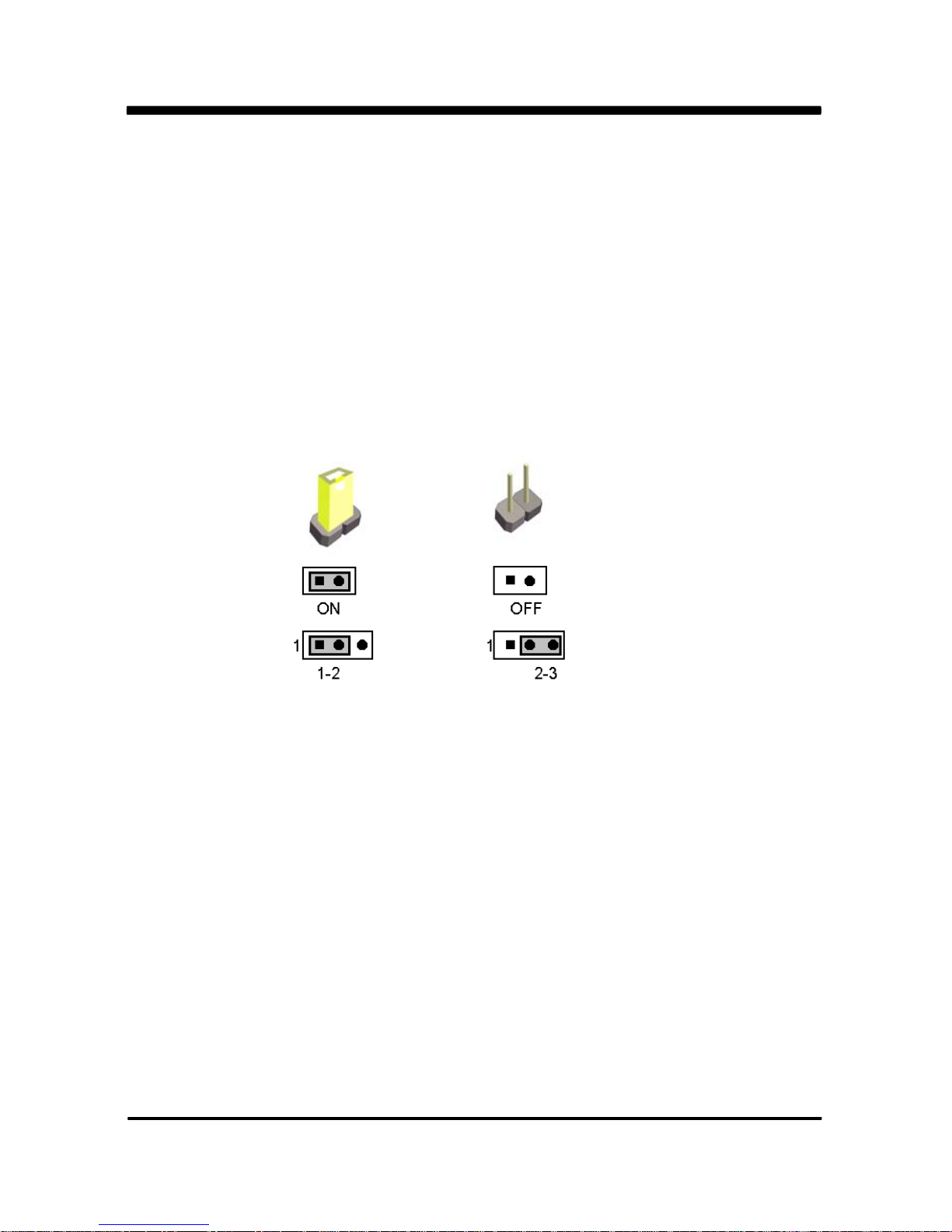
A jumper is ON as a closed circuit with a plastic cap covering two pins. A jumper is OFF
as an open circuit without the plastic cap. Some jumpers have three pins, labeled 1, 2,
and 3. You could connect either pin 1 and 2 or 2 and 3.
The below figure 2.2 shows the examples of different jumper settings in this manual.
2-7 Jumper Setting Description
Figure 2.2
All jumpers already have its default setting with the plastic cap inserted as ON,
or without the plastic cap as OFF. The default setting may be referred in this
manual with a " " symbol .
*
2-6 List of Jumpers
JSB1: CMOS DATA SET
JVL1: LCD panel power select

17
JSB1: CMOS DATA SET
JSB1 Description
*1-2 *Normal Set
2-3 CMOS Data Clear
*Normal
JSB1
2
Clear Setting
13 213
213 213
Note: Do not clear CMOS unless
1. Troubleshooting
2. Forget password
3. You fail over-clocking system
2-9 JVL1: LCD panel power select
JVL1 Description
1-2 +5V
*2-3 +3.3V
Note: Please be cautious about voltage setting.
+5V
JVL1
*+3.3V

18
3-1 List of Connectors
This chapter provides all necessary information of the peripheral's connections,
switches and indicators. Always power off the board before you install the peripherals.
Chapter-3
Connection
CPI1 : DC 12V-IN Power Jack
CPI12 :DC-in 1x2 pin (2.0mm) Wafer connector
CPI11 : DC-In 2x2 pin (4.20mm) Wafer connector (Option)
CBT1 : 3V Battery 1x2pin(1.25mm)Wafer (Option)
BAT1 : 3V Battery hold 2pin
CPO1 : +12V/+5V power output 4 pin (2.0mm) Wafer
CFP1 : FP port 2x5 pin (2.0mm) Wafer
CG1 : VGA DB15 connector (Option)
CG11 : VGA port 2x5 pin (2.0mm) Wafer
DVI1 : DVI-D port connector
HDMI1 : HDMI 1.3a port Type A connector (Option)
LVDS1 : LVDS 18 Bits 2x10 pin (1.25mm) connector
CPP1 : Panel inverter power connector 1x5 pin (2.0mm) Wafer
CT1 : Touch screen device 2x5 pin (2.0mm) Wafer
CA1 : Line-out phone jack
CA3 : Line-out/Line-in/Mic-in 2x5 pin (2.0mm) Wafer
CAR1,CAL1 : Two Channel Speak out ports 2pin (2.0mm) Wafer (Option)
CC1 : COM1 DB9pin connector (Option)
CC2 : COM2 2x5 pin (2.0mm) Wafer
CIO1 : One DIO 2x5 pin (2.0mm) Wafer
CO1 : I C 4pin (1.25mm) Wafer
CL1 : LAN port RJ45
CL1 : LAN port 2x4pin (2.0mm) Wafer (Option)
CU1 : USB1 port Type A connector (Option)
CU11 : USB1 port 4pin(1.25mm) Wafer
2
 Loading...