

Page 1
Assembly Guide
6G8181-2202-0100
Page 2
BRIK 3.5" HDD Assembly guide
1
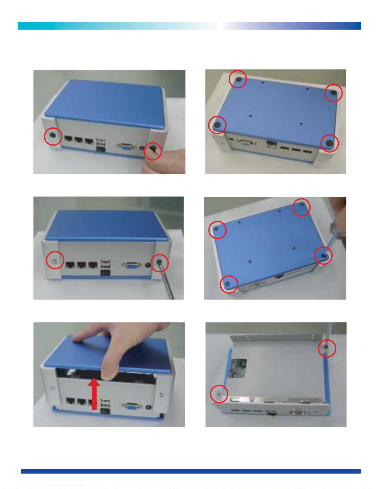
1. Remove 6 foot stands from back panel and bottom cover. (Fig.1) (Fig.2)
2. Remove 6 screws (Flat Screw Type: M3*6). (Fig.3) (Fig.4)
3.Remove upper cover. (Fig.5)
4. Remove 2 screws from HDD Kit
(Round Screw Type: M3*5).
(Fig.6)
(Fig.1)
(Fig.3)
(Fig.5)
(Fig.2)
(Fig.4)
(Fig.6)
Page 3
2
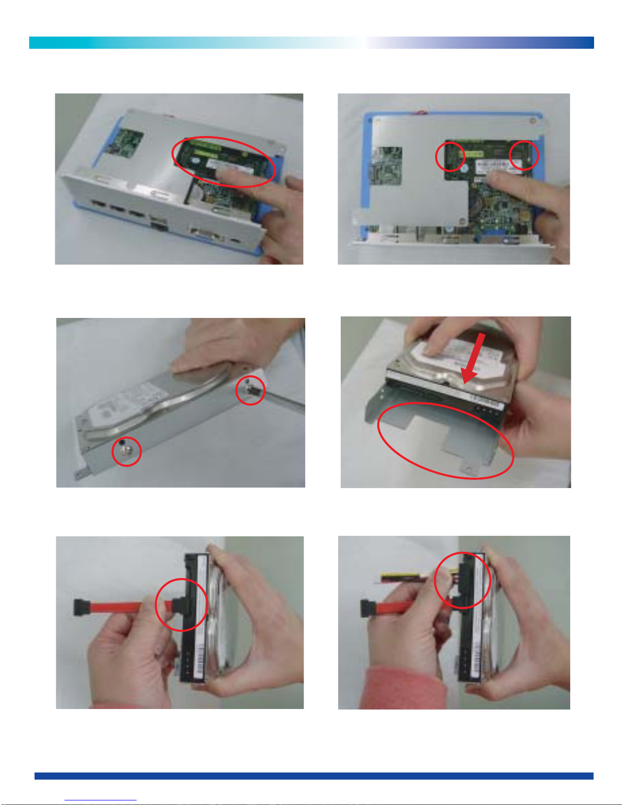
5. Insert SO-DIMM module into memory
slot at a 45-degree angle.
(Fig.7)
6. Push down memory module to get it
hold by 2 fasteners firmly.
(Fig.8)
7. Screw on the fitted HDD with bracket by 4 screws (Attention: please pay attention to
the direction of HDD; Truss Screw Type: M3*5).
(Fig.9) (Fig.10)
8. Connect SATA cable. (Fig.11) 9. Connect SATA power cable. (Fig.12)
(Fig.7)
(Fig.9)
(Fig.11)
(Fig.8)
(Fig.10)
(Fig.12)
Page 4
3
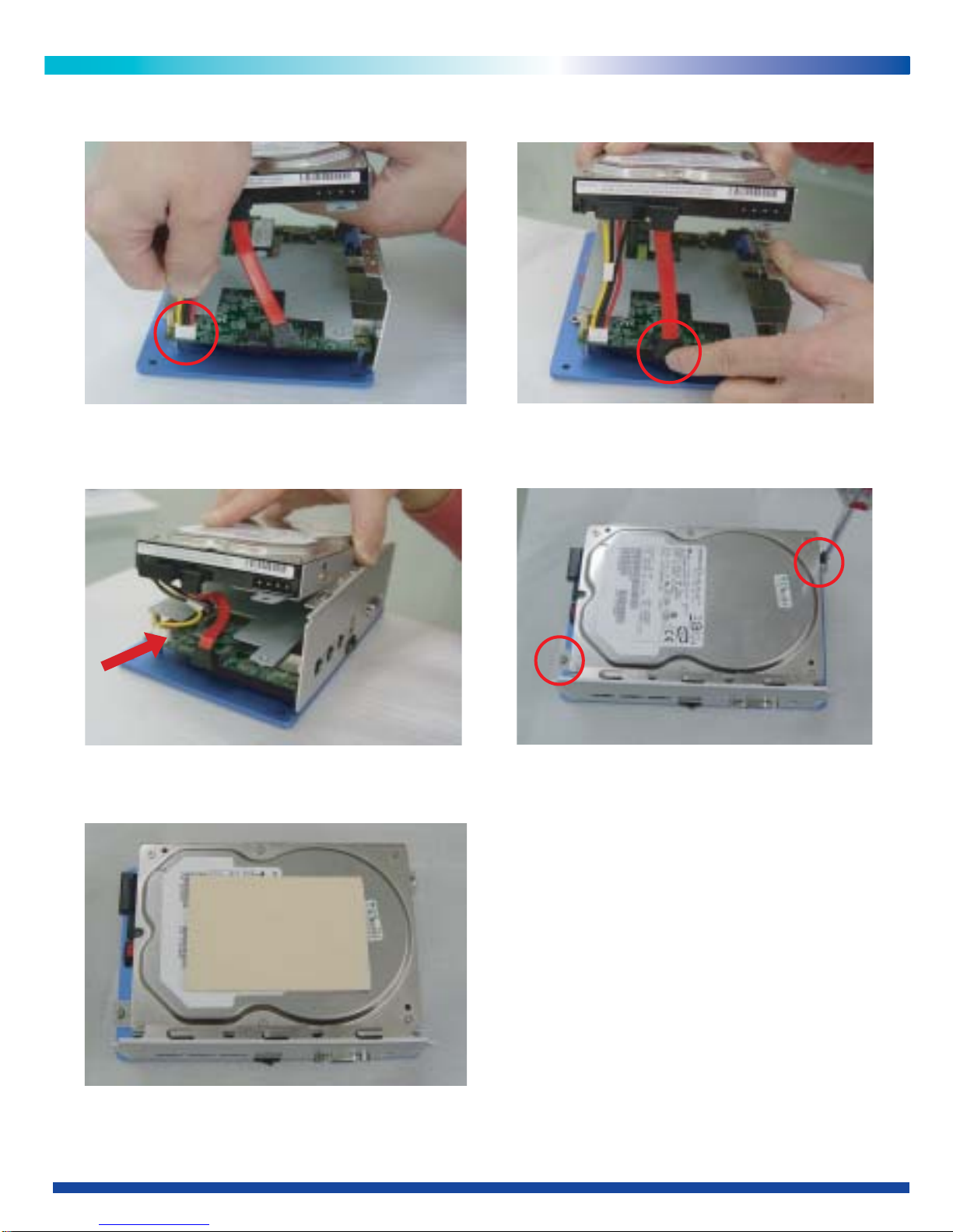
10. Connect SATA power cable to
mainboard.
(Fig.13)
11. Connect SATA cable to mainboard.
(Fig.14)
12. Screw on the HDD Kit device bracket by 2 screws
(Round Screw Type: M3*5).
(Fig.15) (Fig.16)
13. Paste the thermal Pad on HDD. (Fig.17)
(Fig.13)
(Fig.15)
(Fig.17)
(Fig.14)
(Fig.16)
Page 5
4
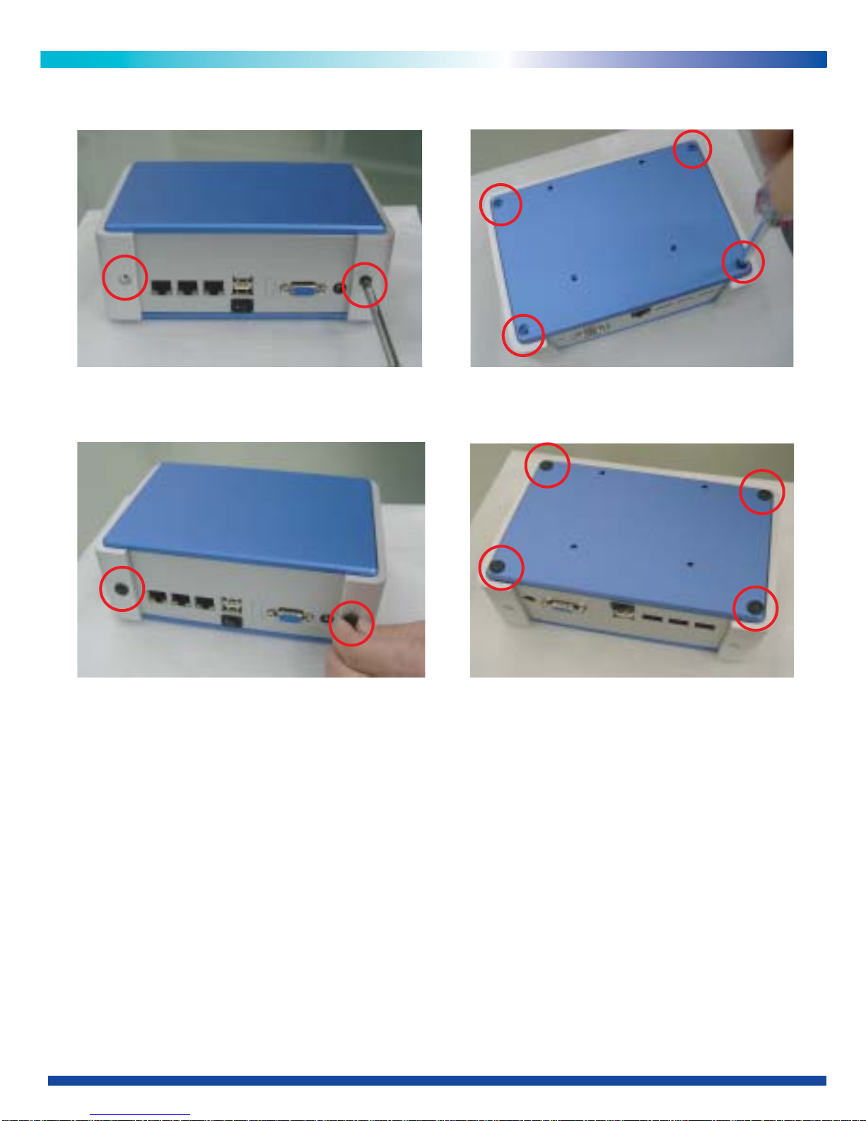
14. Cover the upper cover and screw on back panel and bottom cover by 6 screws
(Flat Screw Type: M3*6).
(Fig.18) (Fig.19)
15. Put the 6 foot stands on back panel and bottom cover. (Fig.20) (Fig.21)
(Fig.18)
(Fig.20)
(Fig.19)
(Fig.21)
Page 6
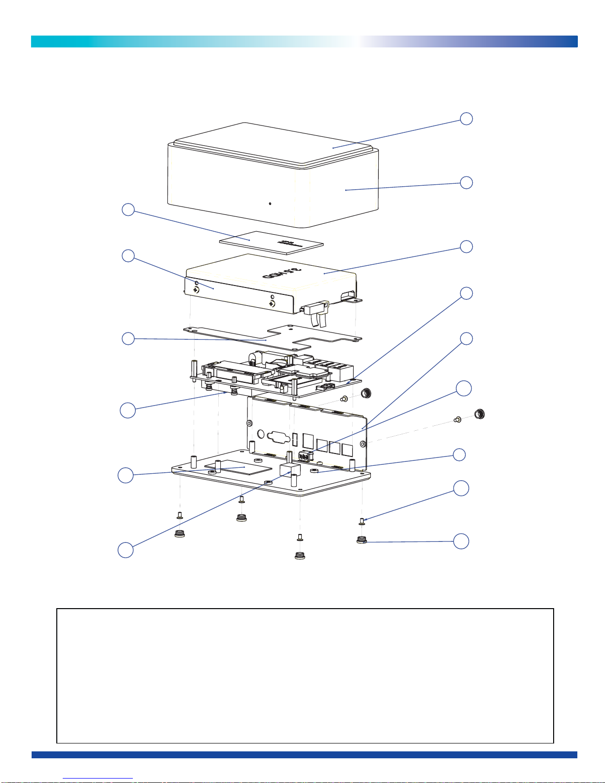
BRIK 3.5" HDD Exploded Drawing
5
1. BRIK,Top Cover,
2. BRIK,Chassis,
3. BRIK,Bottom Cover,
4. Back Panel
5. Main Board
10. Heat Sink,For CPU
6. 3.5"HDD
7. HDD Bracket
8. HDD Kit,
9. Thermal Pad (HDD)
12. Thermal Pad (SB)
11. Thermal Pad (CUP/NB)
13. Switch
14. Screw
15. FOOT
Dimension: 73(H) x 187(W) x 130(D) mm
1
4
12
15
14
11
5
2
13
7
8
9
6
10
3
Page 7
Assembly Guide
6G8181-2202-0100
 Loading...