

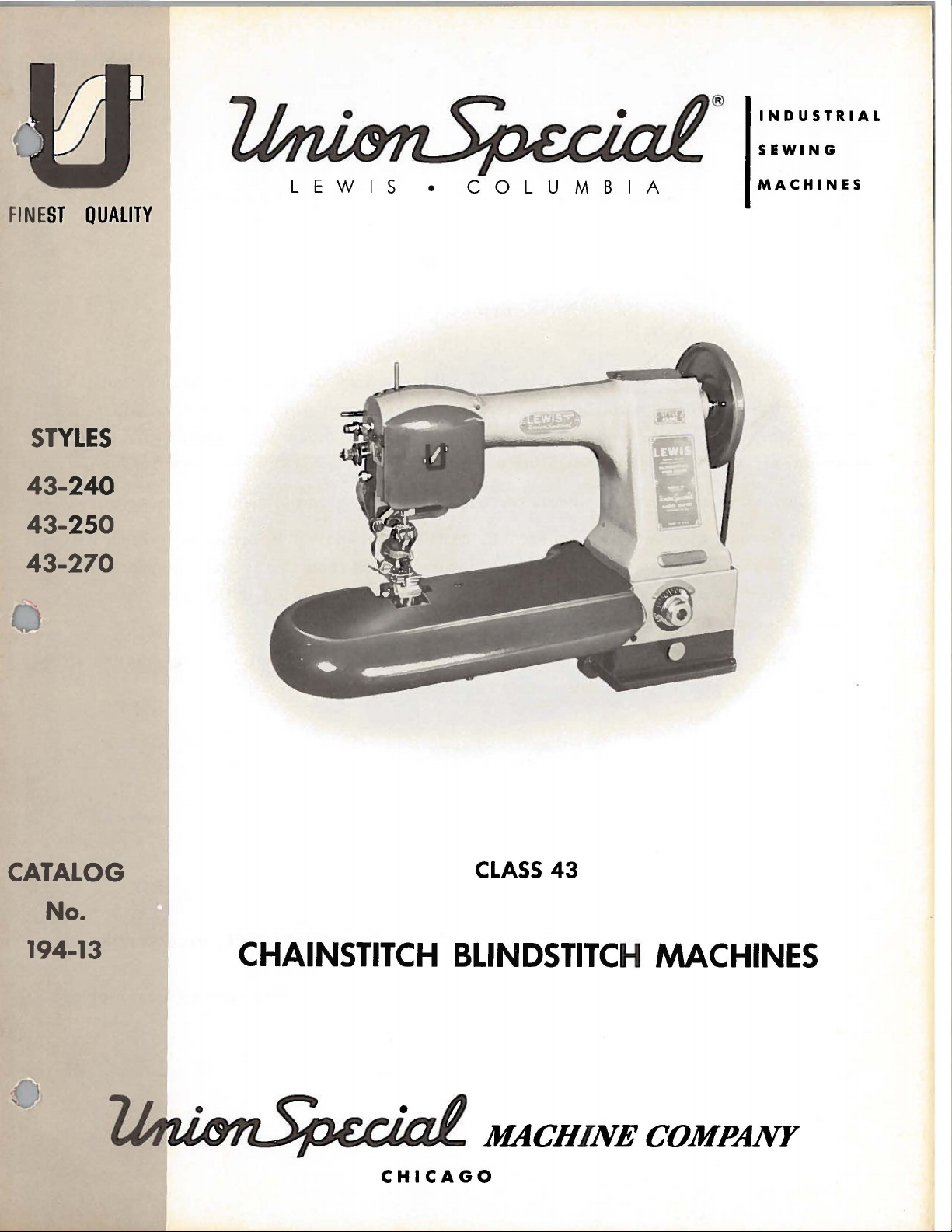
Lewis 43-240, 43-250, 43-270 User Manual
®
INDUSTRIAL
SEWING
FINE
ST
ST
YLES
43-
240
43-
25
43-270
QUALITY
0
LEWIS
•
COLUMBIA
MACHINES
CATALOG
CLASS
43
No.
194-13
'
CHAINSTITCH
BLINDSTITC
MACHINE
CHICAGO
H
MACHINES
COMPANY
The
Union
Special
Lewis
FOREWORD
Class
43
offers
a
line
of
single
thread
chainstitch
blindstitch
also
sweaters
enable
The
and
cooperate
offers
All
parts
It
is
the
following
describe
Union
machines
a
bottom
,
knit
are
our
constant
customer
pages
the
Special
in
planning
with
feed
dresses
made
to
secure
contain
parts
for
representatives
and
top
and
only
and
similar
by
precision
aim
to
all
valuable
Class
estimating
bottom
machine
garments.
furnish
possible
43.
will
feeds
for
methods
carefully
advantages
operating
be
requirements.
for
making
insuring
found
coat
work
mock
complete
prepared
from
and
adjusting data,
in
all
manufactur
and
full
fashion
interchangeability.
information
the
use
of
work
Union
and
ing cente
on
furs.
marks
which
Specials.
illustrate
rs
It
on
will
to
~
Enginee
MACHINECOMPANY
rin
g De
partment
Catalog
INSTRUCTIONS
No.
FOR
194-13
ADJUSTING
LIST
43-240
First
AND
OF
Styles
43-250
Edition
OPERATING
PARTS
43-270
Union
Rights
Copyright
by
Special
Reserved
19
Machine
in
All
6 4
Countries
MACHINE COMPANY
INDUSTRIAL
Printed
October.
1969
SEWING
CHICAGO
i n
3
MACHINES
U.S.
A.
Co.
Each
is
stamped
stamped
Union
in
in
the
Special
the
lug
style
also,
Lewis
plate
on
IDENTIFICATION
machine
on
the
the
front
carries a style
front
of
the
of
the
column,
nF
MACHINES
column.
number,
The
which,
serial
in
this
number
class
of
each
of
machines,
machine
is
This
to
direction,
position
The
while
operating
High
Base
Angle
Machine,
of
Inserting
is 9 Inches.
43-240
For
for
padding collars
light,
plies
43-250
Similar
penetration
the
finest
which
needle
43-270
For
light, _nedium
ped
with
needle
Use
only
on
the
shank.
The
type
catalog
are
are
available
The
following
catalog
applies
such
seated
direction
Production,
Non-Skip 1 to 1 Stitch,
90
Degrees
and
Removing
blindstitch
medium
for
quality
to
Style
from
furs.
prevents
{size . 035).
making
lower
{size • 045),
genuine
number
given
in
in
all
types
specifically
as
right
at
the
Single
to
Line
Work,
felling
and
and
heavy
work.
43-240
skin
Upper
and
unnecessary
mock
and
heavy
feed
full
only.
Union
of
the
the
machine
the
required
and
APPLICATION
and
left,
machine.
of
the
handwheel
DESCRIPTION
Thread,
of
Feed,
Work
bridle
lapels,
and
materials,
Seam
specification
except
side.
Skins
lower
fullness,
fashion
materials.
Seam
Special
Lewis
needles
style
sizes
sizes
are
to
the
styles
forward
and
is
OF
Single
Curved
Needle
Calibrated
Support
and
for
Plate,
edge
tacking
tape
Upper
104-SSm-1,
equipped
are
stitched
feed
adjustments
Seam
marks
on
Every
specification
NEEDLES
needles.
recommended
description.
in
both
uniform
available:
OF
CATALOG
of
machines
back,
away
from
MACHINES
Needle,
Travels
Penetration
Maximum
on
men's
the
canvas
and
lower
for
fur
work,
without
allow
specification
sweaters,
stitch
evenly
104-SSm-1
They
for
each
Needles
blade
listed
etc, , are
the
operator.
Chainstitch,
Left
to
Work
medium
to
facing
feeds
Type
Presser
distorting
perfect
104-SSm-1,
knit
dresses
spaced
are
stamped
style
for
the
and
ball
herein,
taken
Blindstitch,
Right
and
Adjustment,
Space
weight
on
seamed
give
positive
29-123
1/2
foot
or
feeding
and
for
quality
modified,
with
of
machine
Lewis
eye.
All
from
Penetrates
Knee
to Rig
suit
needle
regulated
cutting
at
lining
Type
knitted
work,
Type
the
word
covered
Class
references
the
operators
Lifter
ht
of
coats.
edge
control
{size.
the
and
29-123
garments
29-134
"LEWIS"
43
machines
Cylinder
at
an
for
Needle
Also
coats
of
all
035).
depth
hairs
skins.
1/2
of
Equip-
1/2
by
this
of
of
of
Selection
material
a
good
When
To
needle,
Type
29-123
being
stitch
sewing,
have
or
the
Uniform
29-123
29-123
29-124
29-124
Uniform
Scarfed
29-34
of
the
sewn.
formation,
immediately
needle
~e
number
1/2
'.
Blade
Blade
proper
Thread
orders
1/2
1/2
needle
or
promptly
should
Blade
.
. 035
•
, 045
Blade
.
size
yarn
discard
be
Dia
•
11
030
11
11
040
II
Dia,
040"
is
determined
should
pass
any
and
accurately
forwarded,
freely
needle
A
Ball
Eye
29-132
29-133
29-133
29-134
29-134
29-135
by
through
which
filled,
complete
4
1/2
1/2
1/2
1/2
size
may
Blade
Dia.
, 025
.
030"
•
035
•
040
, 045
•
055
of
thread
needle
have a hooked
an
empty
order
would
II
11
11
II
11
used
eye
in
container,
read:
and
order
or
"100
weight
to
blunt
a
Needles,
of
produce
point.
sample
ILLUSTRATIONS
ORDERING
REPAIR
PARTS
This
views
seen
will
number
the
used
indicated
assembly.
The
complete
this
the
of
in
be
Numbers
position
in
Component
4115-72
1307
121-3
It
will
reason
At
the
book.
part
catalog
various
their
found a listing
of
pieces
ordering
by
Example:
L
be
is
sub-
back
This
number
has
sections
actual
required
in
the
first
of
that
parts.
parts
indenting
Feed
noted
assembly
in
that
replacement
of
the
will
is
known.
position
been
of
column
part
in
Always
of
sub-
their
and
Plunger
Plunger
the
above
should
book
facilitate
arranged
of
the
in
the
the
parts
in
the
the
assemblies
descriptions
Plunger
Barrel--------------------------------
Frame--------------------------------
example
of
be
will
be
locating
to
simplify
mechanism
machine.
with
particular
are
reference
illustration.
use
the
part
Bearing
that
this
part
ordered.
found a numerical
the
are
On
their
view
Reference
number
which
under
Block,
the
individually
illustration
ordering
part
being
numbers
can
the
plunger
repair
shown
the
so
page
numbers,
be
description
complete----------
index
shown.
only,
numbers
listed
furnished
bearing
is
not
and
opposite
of
parts.
that
the
parts
the
description
and
merely
should
in
the
second
for
repairs
of
the
block
recommended,
all
the
description
is
parts
Exploded
may
illustration
and
indicate
never
column.
main
not
shown
when
the
are
sub-
1
1
1
listed.
so
the
only
be
be
in
Where
Part
Union
Machine
according
precision.
trade
forwarded
wise
numbers
Success
Special
Genuine
mark
Prices
directed.
the
construction
represent
in
the
Lewis
Company,
to
the
Maximum
needles
is
your
are
net
f. o.
b.
A
USE
GENUINE
operation
Needles
its
subsidiaries
most
shipping
charge
approved
efficiency
are
packaged
guarantee
cash
the
and
point.
is
IDENTIFYING
permits,
same
subject
made
part,
NEEDLES
of
these
and
scientific
and
with
of
the
Parcel
to
Repair
and
durability
highest
to
cover
each
machines
TERMS
part
regardless
AND
Parts
authorized
principles,
labels
change
Post
postage
PARTS
is
REP
can
as
are
marked
quality
without
shipments
stamped
of
cc;talog
AIR
be
furnished
distributors.
assured.
LEWIS
in
materials
notice.
and
insurance.
with
PARTS
secured
and
are
are
its
in
which
only
by
the
They
made
~
and
All
insured
part
Union
workmanship.
shipments
unless
they
with
are
with
number.
appear.
genuine
Special
designed
utmost
•
This
are
other-
5
The
recommended
speed
of
SPEED
these
machines
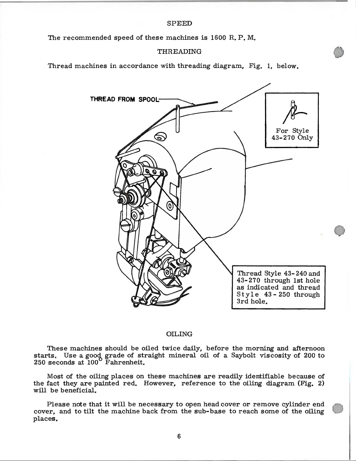
THREADING
is
1600
R.
P.M.
Thread
machines
THREAD
in
accordance
FROM
with
threading
SPOOL;--..__
diagram,
Fig.
1,
below.
For
43-270
Style
Only
These
starts.
250
seconds
Most
the
fact
will
be
Please
cover,
places.
machines
Use
a goo<b
at
100
of
the
they
are
beneficial.
note
and
to
tilt
oiling
painted
that
the
grade
it
should
be
of
Fahrenheit.
places
on
red.
will
be
machine
oiled
twice
straight
these
However,
necessary
back
from
OILING
daily,
mineral
machines
reference
to
open
the
6
before
oil
of a Saybolt
are
readily
head
sub-base
to
the
cover
to
Thread
43-270
as
indicated
Style
3rd
hole.
the
morning
identifiable
oiling
or
reach
Style
through
43-
viscosity
diagram
remove
some
43-
1st
and
250
through
and
afternoon
of
because
cylinder
of
the
240
and
hole
thread
200
(Fig.
oiling
to
of
2)
end
7
Fi
g. 2

ADJUSTING
INSTRUCTIONS
REMOVING
the
arm
cover
TIMING
the
shaft.
looper
gear
if
the
the
wheel
same
right
timing.
in
operating
(the
turned
arrow
time
pointing
the
The
main
looper
Therefore,
cam
should
arrow
left
side
is
arrow
side
open
second
in
on
the
slightly
two
screws
NEEDLE
turned
operating
the
arrow
EXCESS
Fig.
plate
shaft
cam
and
be
in
on
of
drive
is
of
gear
front
direction
screw
cam
Fig.
WITH
(B)
on
line.
gear
in
the
in
line
around
will
on
above
in
drive
the
(A).
gear
PLAY
3
back
drive
into
PLUNGER
gear
are
spotted
arrow
the
right
The
(C)
points
gear
(A),
operating
with
To
cover
and
until
as
direction)
then
(C)
horizontal
gear
5
IN
CONNECTING
position.
(A.
Fig.
on
the
on
the
hub
side
of
the
timing
or
to
as
is
the
the
direction
the
arrow
check
the
the
be
should
for
turn
handwheel
spot
handwheel
in
the
looper
in a horizontal
coincide
as
(A)
and
slide
Oil
set
at
be
necessary
shake
ing
rod
top
of
arm
out
of
position
Tighten
rod
until
wheel
which
screw
Repeat
connecting
rod
screws
4)
and
main
of
the
drive
correct
line
on
hand-
this
on
the
proper
screw
is
cam
with
in
Fig.
gear
mesh.
until
Do
this
the
not
position.
arrow
a
horizontal
the
left
screw
shaft.
alignment
Fig.
gear
(C)
4).
(A)
to
position
the
spot
the
arrow
until
line
arrows
with
screw
RODS
clearance
the
factory.
that
may
adjusting
(Fig.
screw
machine
is
being
is
away
until
the
the
same
rod
(B)
(B.
position
the
5.
If
to
the
Turn
handwheel
spot
turn
the
points
position.
so
the
lines
Retighten
of
If
the
to
the
the
left
gear
on
the
alignment.
spot
and
set
for
Due
to
remove
develop.
screws
3).
Swing
for
access
(A)
in
plunger
begins
turned
from
operator.
machine
procedure
and
feed
and
(C)
Fig.
5)
is
pointing
arrow
on
adjustment
right
in
until
looper
handwheel
to
up
Now,
the
gear
turn
right
teeth
with
the
the
arrows
arrows
right
(A)
or
so
once
right
spot
main
line
up
and
on
main
the
screw
the
connecting
to
normal
any
excessive
Access
is
through
the
to
adjusting
drive
to
bind
in
operating
again
for
driving
respectively.
Fig.
4
toward
to
the
the
cam
is
necessary,
the
gears
in
operating
cam
is
after
gear
and
is
Slide
drive
mesh
the
spot
screws.
on
gears
do
not
again
as
required.
screw
shaft
and
Repeat
the
spot
shaft,
in
then
drive
wear
to
connect-
opening
arm
cover
screws.
connecting
while
direction.
Then,
turns
feed
elevating
connecting
the
front.
right.
at a position
no
direction
to
the
the
spot
(C)
until
slightly
gear
and
the
on
the
Now,
(A
line
up.
and
turn
lines
up
again
this
procedure
screw
tighten
gear
rods
it
may
play
plate
hand-
loosen
freely.
Swing
The
At
this
loosen
longer
front.
is
the
above
(A)
spot
main
check
and
C.
slide
gear
Re-
with
check
is
spot
(A).
is
or
in
in
to
in
8
It
may
play
or
gears
wear
or
and
by
top
or
excess
turn
inserting a screwdriver
of
handwheel
the
machine
also
bind
(A
and
that
C,
replacement.
play,
bushing
the
shaft.
in
operating
does
be
may
Fig.
loosen
ADJUSTING
necessary
have
5)
set
(B)
in
the
Tighten
not
bind.
to
developed
as a result
To
remove
screw
required
in
the
screw.
direction
INSTRUCTIONS
remove
any
between
of
normal
any
bind
(A,
Fig.
6)
direction
oil
hole
on
Turn
to
be
the
sure
(Continued)
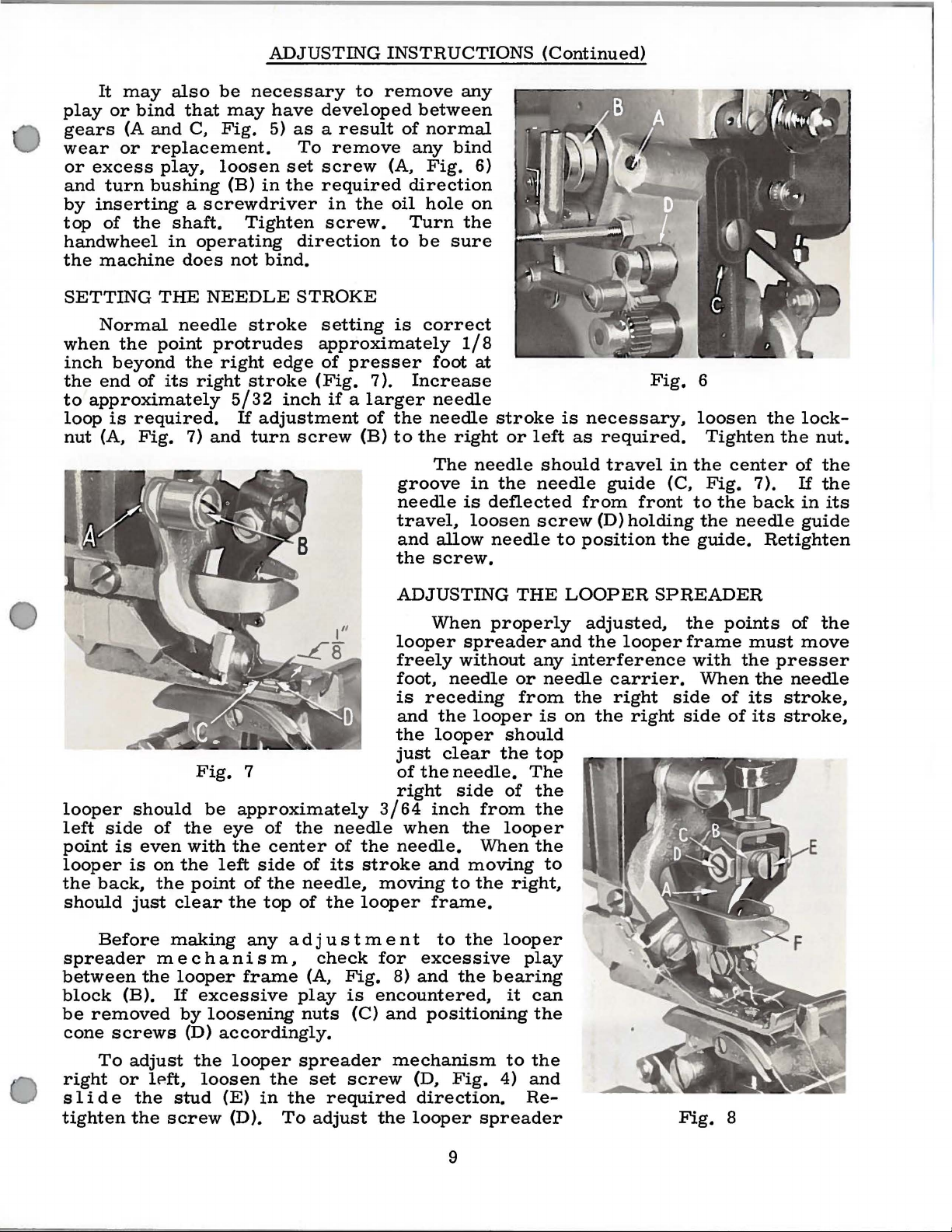
SETTING
Normal
when
inch
the
to
loop
nut
looper
left
point
looper
the
should
the
beyond
end
of
approximately
is
required.
(A,
Fig.
should
side
is
even
is
back,
just
THE
needle
point
its
of
the
on
the
the
clear
NEEDLE
protrudes
the
right
right
5/32
7)
and
Fig.
be
eye
with
the
left
point
the
STROKE
stroke
setting
approximately
edge
stroke
If
adjustment
turn
(Fig.
inch
screw
of
if a larger
7
approximately
of
the
needle
side
of
center
the
top
of
of
its
needle,
of
the
is
presser
7).
of
the
(B)
to
groove
needle
travel,
and
the
ADJUSTING
looper
freely
foot,
is
and
the
just
of
right
3/64
the
needle.
stroke
moving
looper
correct
foot
Increase
needle
needle
the
right
The
allow
screw.
When
needle
receding
the
looper
clear
the
needle.
inch
when
and
to
frame.
1/8
at
stroke
or
needle
in
the
is
deflected
loosen
needle
properly
spreader
without
looper
should
the
side
of
from
the
looper
When
moving
the
right,
left
should
needle
screw
THE
any
or
needle
from
is
top
The
the
the
the
to
is
necessary.
as
required.
travel
guide
from
(D)
to
position
LOOPER
adjusted,
and
the
interference
carrier.
the
right
on
the
Fig.
in
(C,
front
holding
the
SPREADER
looper
side
right
side
6
loosen
Tighten
the
Fig.
to
the
the
guide.
the
points
frame
with
When
of
the
center
7).
back
needle
Retighten
must
the
the
its
of
its
lock-
the
nut.
of
the
If
the
in
its
guide
of
the
move
presser
needle
stroke,
stroke,
Before
spreader
between
block
be
removed
cone
screws
To
right
s 1
or
ide
tighten
making
mechanism,
the
looper
(B).
If
by
adjust
lP.ft,
the
stud
the
screw
frame
excessive
loosening
(D)
accordingly.
the
looper
loosen
(E)
(D).
any
adjustment
the
in
the
To
check
(A,
Fig.
play
nuts
is
(C)
spreader
set
screw
required
adjust
to
the
for
excessive
8)
and
the
encountered,
and
positioning
mechanism
(D.
Fig.
direction.
the
looper
9
looper
play
bearing
it
can
the
to
the
4)
and
Re-
spreader
Fig.
8
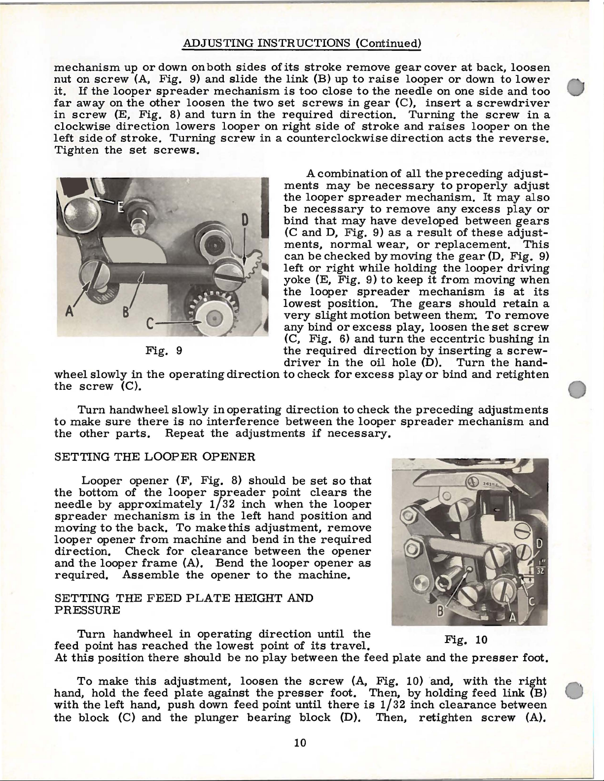
ADJUSTING
INSTRUCTIONS
(Continued)
mechanism
nut
on
screw
it.
If
the
far
away
in
screw
clockwise
left
side
of
Tighten
wheel
the
the
slowly
screw
up
or
(A,
looper
on
the
(E,
Fig.
direction
stroke.
set
C
Fig.
in
the
(C).
down
Fig.
spreader
other
8)
lowers
Turning
screws.
9
operating
on
both
9)
and
loosen
and
turn
sides
slide
mechanism
the
looper
screw
the
two
in
the
on
in a counterclockwise
D
direction
of
its
link
is
too
set
required
right
ments
the
be
bind
(C
ments,
can
left
yoke
the
lowest
very
any
(C,
the
driver
to
check
stroke
(B)
screws
side
A
looper
necessary
that
and
be
or
(E,
looper
slight
bind
Fig.
required
remove
up
close
direction.
of
combination
may
may
D,
Fig.
normal
checked
right
Fig.
position.
or
6)
in
the
for
to
raise
to
the
in
gear
stroke
be
necessary
spreader
to
remove
have
9)
wear,
by
while
9)
to
spreader
motion
excess
and
turn
direction
oil
excess
gear
needle
direction
of
as a result
moving
holding
The
between
hole
cover
looper
on
(C),
insert a screwdriver
Turning
and
raises
all
the
to
mechanism.
any
developed
or
replacement.
the
keep
play,
it
mechanism
gears
loosen
the
eccentric
by
(D).
play
or
from
inserting a screw-
at
back,
or
down
one
side
the
screw
looper
acts
the
preceding
properly
It
excess
between
of
these
gear
the
looper
moving
should
them~
Turn
bind
To
the
and
loosen
to
lower
and
on
reverse.
adjust-
adjust
may
play
gears
adjust-
This
(D,
Fig.
driving
when
is
at
retain
remove
set
screw
bushing
the
hand-
retighten
too
in
the
also
or
9)
its
in
a
a
Turn
to
make
the
other
SETTING
the
bottom
needle
spreader
moving
looper
direction.
and
the
required.
SETTING
PRESSURE
Turn
feed
At
this
To
hand,
with
the
block
handwheel
sure
Looper
by
to
opener
looper
point
position
make
hold
the
left
slowly
there
parts.
THE
opener
of
approximately
mechanism
the
back.
from
Check
frame
Assemble
THE
handwheel
has
reached
this
the
hand,
(C)
and
is
Repeat
LOOPER
(F,
the
looper
To
machine
for
FEED
there
adjustment,
feed
plate
push
the
in
no
interference
the
OPENER
Fig.
SJlreader
1/32
is
in
make
clearance
(A).
the
opener
PLATE
in
operating
the
should
against
down
plunger
operating
adjustments
8)
should
inch
the
left
this
and
bend
Bend
lowest
the
HEIGHT
be
no
loosen
feed
bearing
direction
between
be
point
when
hand
adjustment,
between
looper
to
the
direction
point
play
the
presser
point
the
position
in
the
the
machine.
AND
of
between
the
screw
until
block
the
if
necessary.
set
so
clears
looper
remove
required
opener
opener
until
its
travel.
the
foot.
there
(D).
to
that
the
and
the
(A,
check
looper
as
feed
Fig.
Then,
is
1/32
Then,
the
preceding
spreader
plate
10)
by
inch
retighten
mechanism
Fig.
and
the
and,
holding
clearance
adjustments
10
presser
with
feed
screw
the
link
between
and
foot.
right
(B)
(A).
10
 Loading...