

Lewis 30-210, 30-220, 30-230, 30-410 User Manual
INDUSTRIAL
SEWING
FINEST
STYLES
30-210
30-2
0-230
0-
20
410
C 0 L U M B I
A®
MACH·INES
CLASS
C TALOG
No.
194-3
SECOND
EDITION
UNI
LOCKSTITCH
ON
SPECIAL
BLI
CHICAGO
DSTITCH
30
MACHI
ES
CORPORATION
Catalog
INSTRUCTIONS
FOR
No.
194-3
ADJUSTING
LIST
30-210
Second
AND
OF
PARTS
Styles
30-220
30-410
Edition
OPERATING
30-230
Rights
UNI
Union
Reserved
ON
SPEC1~4L
INDUSTRIAL
Printed
Copyright
By
Special
SEWING
CHICAGO
1964
Corporation
in
All
Countries
CORPORATION
MACHINES
in
U.S
. A .
2
May,
1981
I
DENTIFICATION
OF
MACHI
NES
Each
ma
chi nes ,
of each mac
th
under
e head cover .
This
re
f r en
ces
from
High Pro
Base
Angle
Knee
30-210
the
operator's
The
operating
duction, Two
Hachine.
of
Need
Lifter for Insertin
to Rig
ht
of
For
suit
Equipped
missing a stitch.
30-220
Same
topcoats
UNION
SPECIAL
is stamped
hin
e
is stamped
catalog
to
dir
applies
ectio
direction
Non-Skip
le
Pe
netration
Needle
10 I
felling
coats
with
as
and
and
automatic
Style
overcoats.
LEWIS mac
in
the S
hine carri
tyle plat
e on the f r o
in the mai n f r ame
APPLICATION
sp
n,
pos
ition whi
ecifical
su
ch
as
ly
righ
le seat
t o t he
t and
ed a t
of the handwheel
DESCRIPTION
Thread,
Single
1
to 1 Stitch.
is
in
Curved
line
Needle
of
g and Removing Work. Work S
nches.
quarter,
sport
Side
30-210
half
coats.
plunger
and
except
Can
lower
Can
or
full
also
to
feed.
equipped
also
be
stitch
be
es a St
OF
left
OF
yl e
nt
of the
at
t he l
CATALOG
Styles
,
for
the
machine .
is away
~~CHINES
numb
eft
of
machin
ward
from
Needle, Lockstitch,
Shog s
Feed.
Cal
or
ibrated
Vibrat
upport
linings
used
Stitching
to
used
of
on
women's
over
pockets
sew medium
on
women's
light
invisible
r , which,
col
umn. Th serial
upp r
and bac
the
main shaf
es
lis
k,
op
rator.
Blindstitch,
es from
Penetra
Plate.
weight
high
without
tion
Maximum Work
material
quality
closing
on
weight
high
material
quality
i n thi s Class
num
t be
arin
t ed herein.
et c
.,
ar e take
Cylind
Sid
e t o
Sid
Adjustment.
Spa
in
men' s
suit
coats.
pocket
completed
lined
seams.
in
coat
men' s
of
b r
g ,
All
n
er
e .
ce
or
s .
30-230
seamed
edge.
pocket
30-410
as
high
without
visible
The recommended
a
blade
29
29
Selection
material
good
stitch
When
point.
For
felling
bottoms
Equipped
or
missing a stitch.
For
felling
tropicals
quality
closing
on
completed
diameter
of
NEEDLE
TYPE
BB-075/029
BB-100/040
of
used.
Thread
formation.
sewing,
medium
only,
with
quarter,
in
men's
suit
coats.
pocket
needle
.036
proper
should
immediately
weight
instead
automatic
half
suit
or
seams.
for
inch
(.90
needle
suit
of
binding
plunger
Stitching
or
full
coats
Equipped
missing
the
machines
mm).
size
pass
freely
discard
coats
or
to
and
p1p1ng.
stitch
invisible
linings
and
sport
with
a
automatic
stitch.
NEEDLES
in
Class
It
is
also
INCHES
.029
.040
is
determin
throu
ed
gh
any needle which
similar
on
of
extra
coats.
Side
30
available
by
needle
Fells
over
completed
light
Can
plunger
and
lower fee
is
Type
SIZE
size
of
eye
may
garments
3/16
pockets
made
inch
without
seam.
toleight
also
be
used
to
stitch
d.
29
BB-090/036.It
in the
thread
in
following sizes:
and
order
have a hooked
with
from
turned
closin
material
on
women' s
over
pockets
Stitching
MILLIHETERS
.75
1.00
weight
to
produce
or
blunt
book
g
su
ch
in-
has
of
a
To
have
a
sample
"100
needle,
Needles,
needle
Type 29
orders
or
the
BB-090/036".
promptly
Type number
and
should
accurately
be
forwarded.
3
filled,
A
complete
an
empty
order
container,
would
read:
Th
e recomm
Thr
e· d
machin
nd
ed speed of
-s
in
accordane
SPEED
these
machin
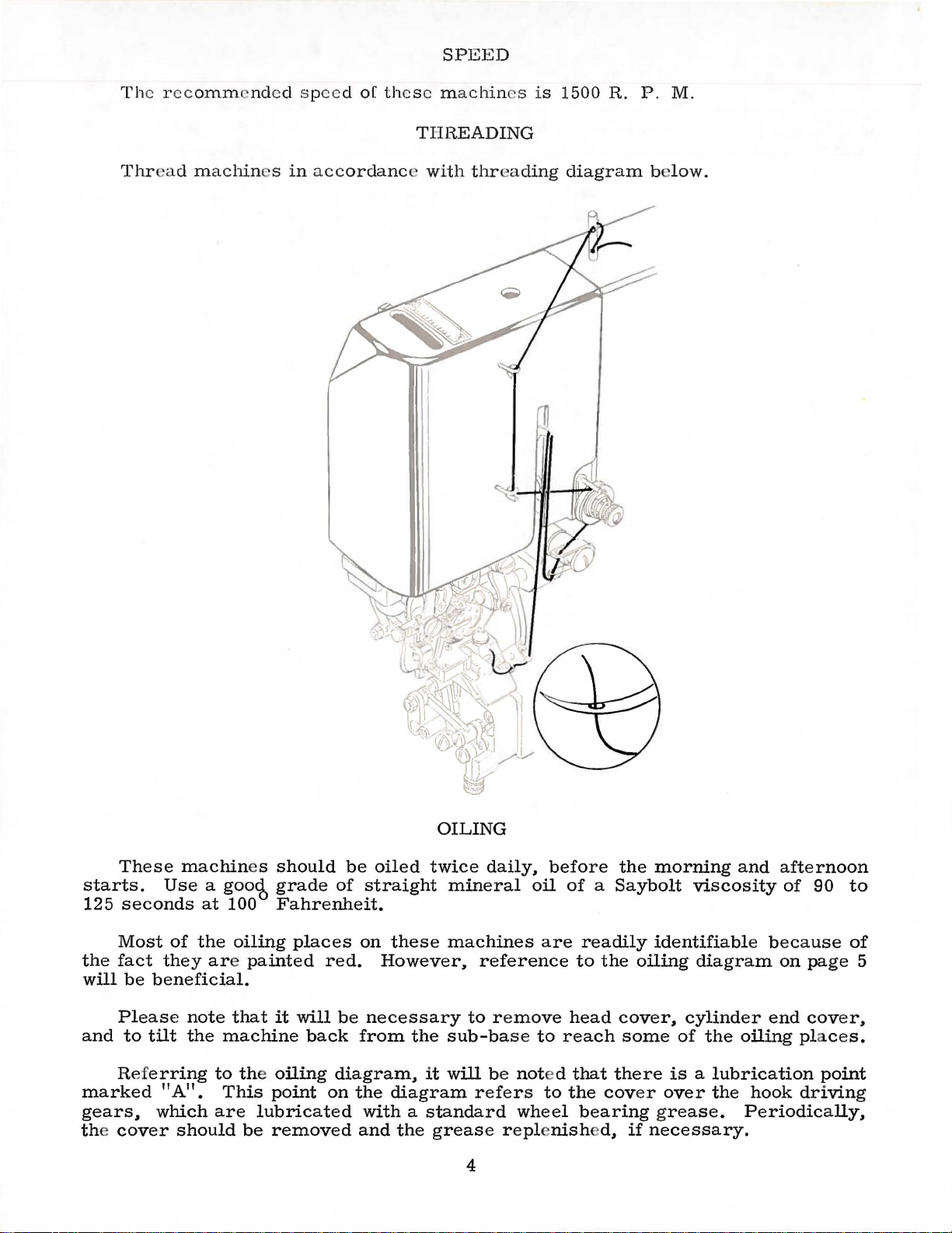
THREADING
with
thr
es
is
ading
1500
R.
diagram
P.
be
M.
low.
OILING
These
starts.
125
seconds
Most
the
fact
will
be
Please
and
to
Referring
marked
gears~
the cover
machin
Use
a gooct,
at
of
the
they are
beneficial.
note
tilt
the
machine
to the
"A".
which
This
are
should
es
100
oiling
painted
that
point
lubricated
be
removed
should
grade
be
of
Fahrenheit.
places
red.
it
will
be
back
oiling
diagram~
on
the
oiled
straight
on
However~
necessary
from
twice
mineral
these
the
it
machines
sub-base
will
diagram
reference
to
refers
with a standard
and
the
grease
daily~
before
oil
are
remove
to
reach
be
not d that
to
wheel
repl
nish
4
the
morning
of a Saybolt
readily
to
the
head
the
cov
identifiable
oiling
cover1 cylinder
some
there
of
is a lubrication
er
over
bearing grease.
d~
if
necessary.
and
viscosity
diagram
the
oiling pla
the
hook
Periodically~
afternoon
of
90
because
on
page
end
cover
point
driving
to
of
5
1
ces.
A
5
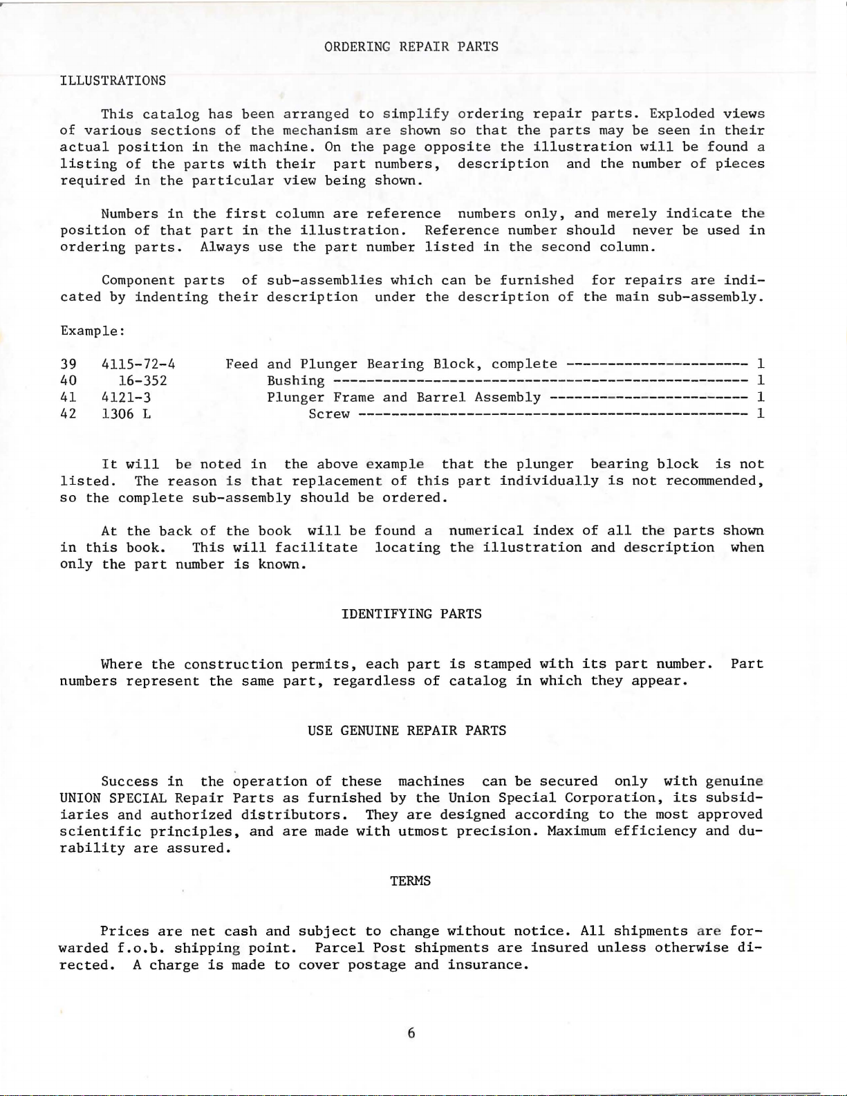
ILLUSTRATIONS
This
catalog
of
various
actual
listing
required
Numbers
position
ordering
sections
position
of
the
in
the
of
that
parts.
has
in the
parts
particular
in
the
part
Always
been
of
the
machine.
with
first
in
arranged
mechanism
their
view
column
the
illustration.
use
the
ORDERING
to
simplify
are
On
the
page
part
numbers,
being
are
part
shown.
reference
number
REPAIR
shown
opposite
Reference
listed
PARTS
or
dering
so
that
the
description
numbers
number
in
the
repair
the
parts
illustration
and
only,
should
second
parts.
and
may
be
will
the
number
merely
never
column.
Exploded views
seen
in
their
be
found
of piece
indicate
be
used
the
in
a
s
Component
cated
Example:
39
40
41
42
listed.
so
in
only
numbers
by
4115-72-4
4121-3
1306 L
It
the
At
this
the
Where
indenting
16-352
will
The
reason
complete
the
back
book.
part
the
represent
parts
be
sub-assembly
This
number
construction
not
of
the
of
their
Feed
ed
i s
the
will
is
same
sub-assemblies
description
and
Plunger
Bushing
Plunger
Screw
in
the
above
that
replacement
should
book
known.
will
facilitate
permits,
part,
which
under
Bearing
-------------------------------------------------Frame
IDENTIFYING
regardless
and
-----------------------------------------------
exampl e
of
be
ordered.
be
found
locating
each
the
Block,
Barrel
this
a
part
of
can
be
furnished
description
complete
Assembly
that
PARTS
the
plunger
part
numerical
the illustration
is
catalog
individually
stamped
in
for
of
the
------------
------------------------
bearing
is
index
with
which
of
and
its
they
all
repairs
main
part
sub-assembly.
-
---------
block
not
recommended,
the
parts
description
number.
appear.
are
indi-
is
not
shown
wh
Part
1
1
1
1
en
USE
Success
UNION
iaries
scientific
rability
warded
rected.
SPECIAL
Prices
and
authorized
principles,
are
f.o.b.
A
charge
in
the
operation
Repair
assured.
are
net
shipping point.
Parts
distributors.
cash
is
made
and
and
as
are
to
GENUINE
of
these
furnished
made
subject
Parcel
cover
They
with
to
postage
machines
by
utmost
TERMS
change
Post
REPAIR
the
Union
are
designed
precision.
without
shipments
and
insurance.
6
PARTS
can
Special
are
be
secured
Corporation,
according
Maximum
notice.
insured
to
All
unless
only
efficiency
shipments
the
with
its
most
otherwise
genuine
subsid-
approved
and
du-
ar e
for-
di-
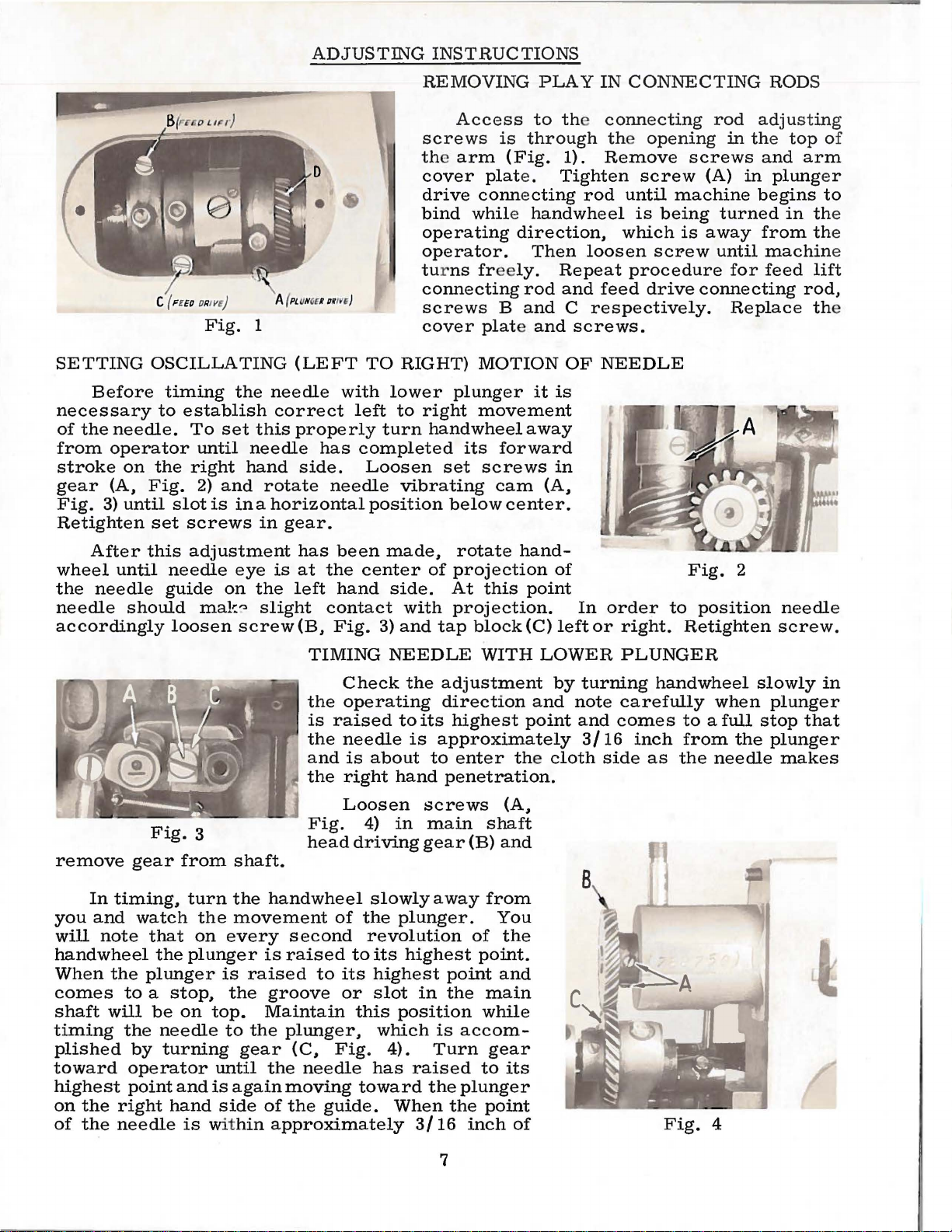
ADJUSTING
INSTRUCTIONS
SETTING
Before
necessary
of
the
needle.
from
stroke
gear
Fig.
opera
on
(A,
3)
until
Retighten
c ( F
EE
D OF/IV£) A {
Fig.
1
OSCILLATING
timing
to
tor
the
Fig.
slot
set
establish
screws
the
To
set
until
right
2)
needle
hand
and
is
in a horizontal
this
rotate
in
D
•
PL
UNGU URWf
(LEFT
needle
correct
properly
side.
gear.
)
with
left
has
needle
REMOVING
screws
the arm
cover
drive
bind
operating
operator.
turns free
connecting
screws
cover
TO
RIGHT)
lower
to
right
turn
handwheel
completed
Loosen
vibrating
position
PLAY
Access
to the connecting
is
through the
(Fig.
plat
e.
connecting
while handwheel
direction.
Then
ly.
rod
B
and
plate and
MOTION
plunger
it
movement
away
its
forward
set
screws
cam
below
(A,
center.
IN
1).
Remove
Tighten
rod
loosen
Repeat
and
feed
C
respectively.
screws.
OF
NEEDLE
is
in
CONNECTING
rod
opening
in the
screws
screw
until
is
which
screw
procedure
drive
(A)
machine
being
is
away
connecting
turned
until
for
Replace
RODS
adjustin
top
and
in
plung
begins
in the
from the
machin
feed
of
arm
er
to
lift
rod,
th
g
e
e
After
wheel
the
needle
until
needle
should
accordingly
remove
you
will
In
timing.
and
note
gear
watch
handwheel
When
comes
shaft
timing
plished
toward
highest
on
of
the
the
the
will
right
needle
to a stop,
the
by
operator
point
this
adjustment
needle
guide
mal-::'3
loosen
Fig.
3
from
turn
the
that
on
the
plunger
plunger
be
on
needle
turning
and
hand
is
eye
on
the
slight
screw(B.
shaft.
the
movement
every
is
raised
the
top.
to
the
gear
until
is
again
side
wit
hin
has
been
is
at
the
center
left
hand
contact
Fig.
TIMING
Check
the
operating
is
raised
the
needle
and
is
the
right
Loosen
hand
Fig.
head
wheel
4)
driving
of
the
second
is
raised
groove
Maintain
to
to
its
or
this
plunger,
(C.
Fig.
the
needle
moving
of
the
toward
guide.
approximately
made,
side.
with
3)
and
rotate
of
projection
At
projection.
tap
NEEDLE
the
adjustment
direction
to
its
highest
is
approximately
about
hand
to
enter
penetration.
screws
in
main
gear
slowly a way
plunger.
revolution
its
highest
highest
slot
in
point
the
position
which
4).
has
Turn
raised
the
When
is
accom-
plunger
the
3/16
hand-
this
block(C)
WITH
point
the
(A,
shaft
(B)
and
from
You
of
the
point.
and
main
while
gear
to
its
point
inch
of
of
point
left
LOWER
by
and
note
cloth
In
order
or
right.
PLUNGER
turning
carefully
and
comes
3/16
side
Fig.
to
Retighten
handwheel
to a full
inch
as
from
the
Fig.
2
position
slowly
when
the
needle
4
needle
screw.
plunger
stop
that
plunger
makes
in
7
th
e center
point
ed
spot
Fig.
of
screw
plunger
in
5
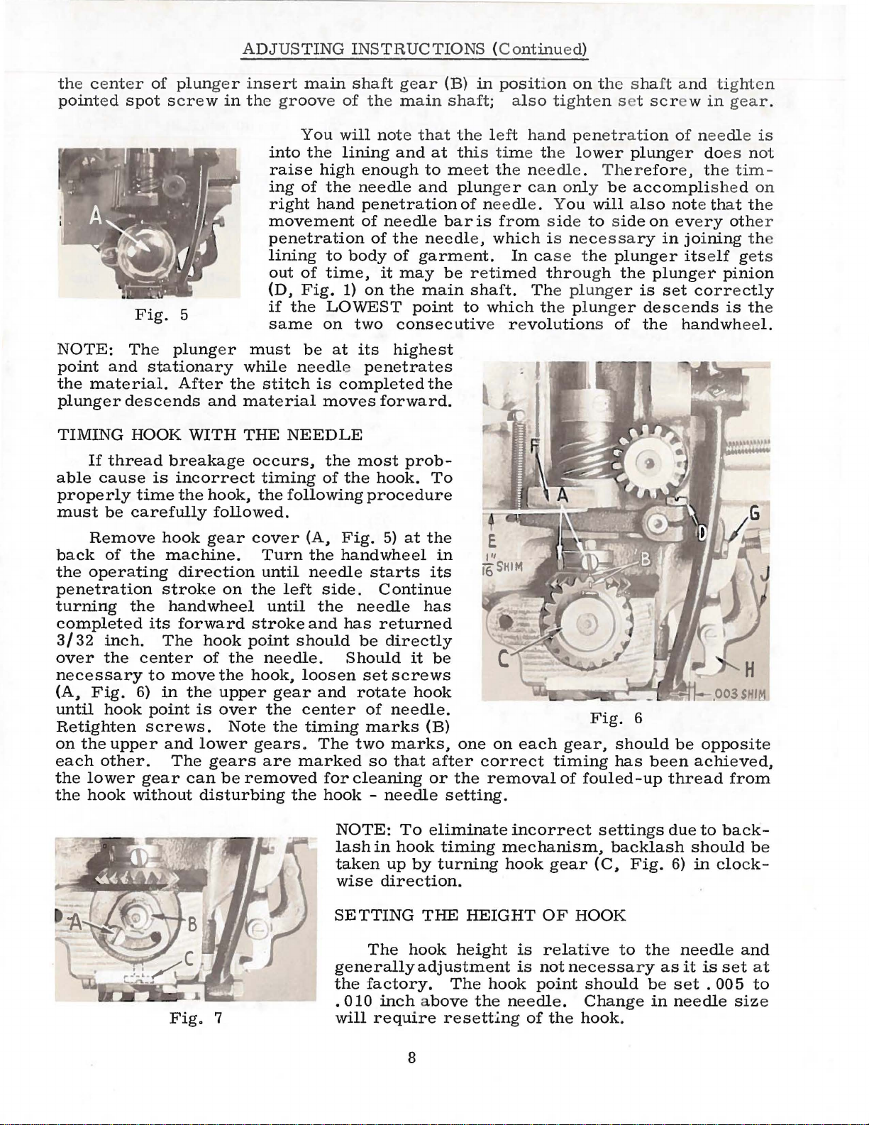
ADJUSTING
insert
the
main
groove
You
into
the
raise
ing
right
movement
penetration
lining
out
(D.
if
same
high
of
hand
of
Fig.
the
the
to
time,
LOWEST
on
INSTRUCTIONS (Continued
shaft
of
will
lining
body
1)
two
gear
the
main
note
that
and
at this time the l o
enough
needle
penetration
of
of
it
on
to meet the needle. Therefor
and
needle
the
needle,
of
garment.
may
the
main
point
consecutiv
(B)
in
position on the shaft
shaft;
the
plunger can only
of needle. Y
bar
be
to
also
left
hand
is
from side to side
which
In case the
r etim ed
shaft.
which the plung
e r e
The plung
volutions of
)
tighten
penetr
ou
is ne c
thr
ough
s et
scr
ati
on
wer
plung
be
accompli
will also
on eve
essa
ry
plunger
the
plung
er
is
er
descends
the
and
tighten
ew
in
gear
of needle
er
do
es not
e, the
note that the
in joi
itself
set
handwheel.
tim-
shed on
ry
oth
ning
get s
er
pinion
correctly
is the
.
is
er
th
NOTE:
point
the
plunger
TIMING
able
properly
must
back
the
penetration
turning
completed
3/32
over
necessary
(A.
until
Retighten
on
the
each
the
the
The plung
and
material.
descends
HOOK
If
thread
cause
be
carefully
Remove
of
the
operating
the
inch.
the
Fig.
hook
upper
other.
lower
hook
stationary
After
breakage
is
incorrect
time
the
hook
machine.
direction
stroke
handwheel
its
forward
The
center
to
move
6)
in
point
screws.
and
The
gear
without
er
the
and
WITH
hook.
followed.
gear
on
hook
of
the
the
the
upper
is
over
Note
lower
gears
can
be
disturbing
must
while
material
THE
occurs.
cover
the
stroke
point
hook.
gears.
removed
needle penetrates
stitch
NEEDLE
timing
the
following
Turn
until
left
until
should
needle.
gear
the
the
are
marked
the
be
at
its
is
completed
moves
the
of
(A.
the
needle
side.
the
and
loosen
and
center
timing
The
for
hook -needle
forward.
most
the
hook.
procedure
Fig.
handwheel
starts
Continue
needle
has
returned
be
Should
set
rotate
of
marks
two
so
cleaning
highest
the
prob-
To
5)
at
the
its
has
directly
it
screws
hook
needle.
(B)
marks.
that
or
in
be
one
after
the
setting.
on
each
correct
removal
Fig.
gear.
timing
of
fouled-up
6
should
has
been
be
opposite
achieved.
thread
from
Fig.
7
NOTE:
lash
taken
wise
SETTING
generallyadjustment
the
.
010
will
To
eliminate
in
hook
up
by
direction.
THE
The
hook
factory.
inch above
require
8
timing
turning
HEIGHT
height
The
the
resethng
incorrect
mechanism.
hook
hook
needle.
is
is
of
not
point
gear
OF
HOOK
relative
necessa
should
Change
the
hook.
settings
backlash
(C.
Fig.
to the
ry
due
6)
needle
as
be
set . 005
in
needle
to
should
in
clock-
it
is
back-
be
and
set
size
at
to
To
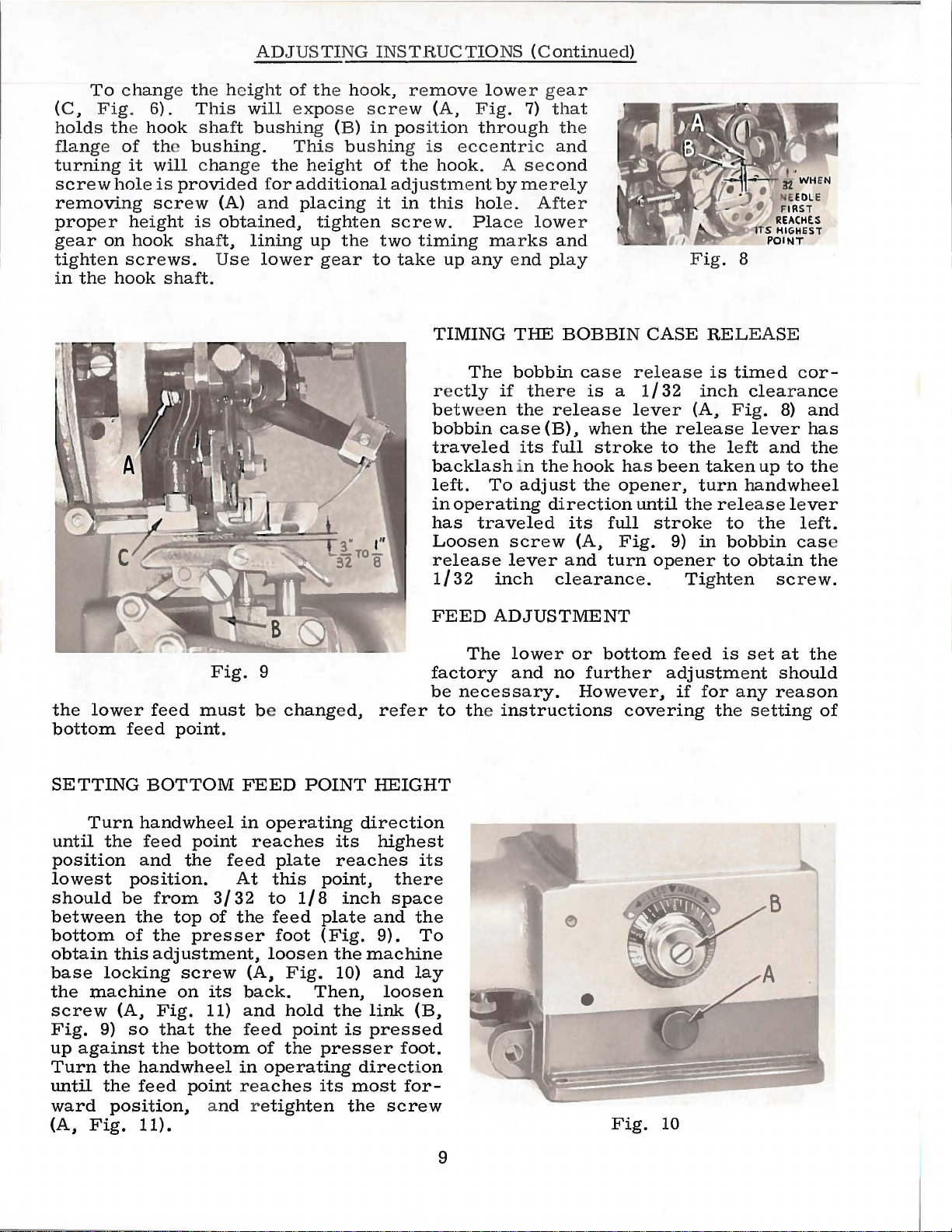
change th
(C.
Fig
. 6).
holds the
flange of
turning
screw
it
hole
removing
proper
gear
tighten
in
the
height
on
hook
screws.
hook
e he
This
hook
shaft
th
bushing.
will
change the
is
provided for
screw
is
shaft,
Use
shaft.
ADJUSTI
ight
will exp
bushin
(A)
and
obtained,
lining
lower
NG INSTB.UC
of the
hook,
ose scr
g (B)
in
This bushin
height
of
additional
placing
it
tighten
up
the
two
gear
to
TIO
r e
move low
ew
(A,
Fig.
position
g is
the
through the
eccentr
hook.
adjustment
in
this
hole.
screw.
Place lower
timing
take
up
any end
NS (C
er gear
7)
ic
A s e
by
merely
marks
ontinued)
that
and
cond
After
and
play
1
..:-
o.11.,.
Fig.
8
'-m'
~·
WHE'N
E
EDL
F
IRS
REACHES
S HIGHE
POINT
T
E
ST
the
lower
bottom
feed
SETTING
Fig.
feed
must
point.
BOTTOM
9
be
changed,
FEED
POINT
TIMING
r e
between
bobbin
traveled
backlash
left.
in
has
Loosen
release
1/32
FEED
factory
be
refer
to the instructions
HEIGHT
THE
The
bobbin
ctly
if
there
the
case
its
in
To
adjust
operating
traveled
screw
lever
inch
ADJUSTMENT
The
lower
and
necessary.
BOBBIN
case
is
release
(B).
when
full
stroke
the
hook
the
direction
its
(A,
and
clearance.
or
no
further
However,
CASE
release
a
1/32
lever
the
has
opener,
until
full
stroke
Fig.
turn
opener
bottom
covering
RELEASE
is
inch
(A,
release
to
the
left
been
taken
turn
the
release
to
9)
in
bobbin
to
Tighten
feed
is
adjustment
if
for
the
timed
cor-
clearance
Fig.
8)
lever
and
up
to
handwheel
lever
the
cas
obtain
screw.
set
at
should
any
reason
setting
and
has
the
the
left.
e
the
the
of
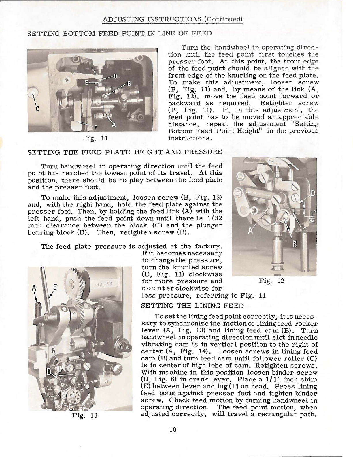
Turn
until
position
lowest
should
between
bottom
obtain
base
the
machine
screw
Fig.
up
against
Turn
until
ward
(A,
Fig.
handwheel
the
feed
and
position.
be
from
the
of
the
this
adjustment,
locking
(A,
9)
so
the
the
handwheel
the
feed
position,
11).
top
screw
on
Fig.
that
in
point
the
reaches
feed
At
3/32
of
the
presser
(A,
its
back.
11)
and
the
feed
bottom
in
point
reaches
a
nd retighten
operating
plate
this
to
1/8
feed
foot
loosen
Fig.
Then,
hold
point
of
the
operating
direction
its
reaches
point,
inch
plate
(Fig.
the
machine
10)
the
link
is
pressed
presser
direction
its
most
the
highest
its
there
space
and
the
9).
To
and
lay
loosen
(B,
foot.
for-
screw
9
Fig.
10
ADJUSTING
INSTRUCTIONS
(Continued)
SETTING
\
c
SETTING
Turn
point
position,
and
and,
presser
left
inch
bearing
has
the
presser
To
make
with
hand,
clearance
BOTTOM
Fig.
THE
handwheel
reached the
there
the
foot.
block
this
right
push
FEED
should
foot.
Then,
the
between
(D).
FEED
11
PLATE
in
operating
lowest
be
no
adjustment,
hand,
by
feed
Then,
hold
holding
point
the
retighten
POINT
HEIGHT
point
play
loosen
the
the
down
block
IN
LINE
tion
press
of the feed
front edge
(B,
Fig.
backward
(B,
feed
distance,
Bottom
instructions.
AND
direction
of
its
between
screw
feed
plate
feed
link
until
(C)
and
screw
OF
FEED
Turn
To
make this
Fig.
until the feed
travel.
the
(B,
(A)
there
the
(B).
the
until
er
foot.
11)
12),
Fig.
point
Feed
PRESSURE
At
feed
Fig.
against the
with the
is
plung
the
point
of
the
and,
move
as
11).
has
repeat
this
plat
12)
1/32
hand
wheel
feed
Point
e
er
point
At
this
should
knurling
adjustment,
by
the
required.
If,
in
to
be
the
Height
in
operating
first
point, the front ed
be
on the feed
means
feed
point
Re
this
moved
adjustment
11
touches
align
ed wit h the
loosen
of the
tight
adjustment, the
an
in the pre
link
forward
en
appreci
"Setting
dir
plat
scr
scr
abl
vious
ec -
the
ge
e.
ew
(A,
or
ew
e
The
feed
plate
Fig.
pressure
13
is
adjusted
If
to
turn
(C,
for
c o u n t
less
SETTING
sary
lever
handwheel
vibrating
center
cam
is
Wi
(D,
(E)
feed
screw.
operating
adjusted
it
becomes
change
the
Fig.
more
pressure,
To
set
to
(A,
(A,
(B)
in
center
th
machine
Fig.
between
point
at
the
factory.
necessary
the pre
knurled
11)
clockwise
pressure
er
clockwise
referring
THE
the
synchronize
cam
and
6)
Check
direction.
correctly,
LINING
lining
Fig.
in
against
13)
operating
is
Fig.
turn
of
high
in
in
crank
lever
feed
14).
ssure,
screw
and
for
feed
the
and
in
vertical
feed
lobe
this
lever.
and
presser
motion
will
Fig.
to
Fig.
FEED
point
motion
lining
direction
position
Loosen
cam
until
of
cam.
position
Place a 1/16
lug
(F)
on
foot
by
The
feed
travel a rectangular
11
correctly,
of
lining
feed
screws
loosen
turning
cam
until
follower
Retighten screws.
head.
and
point
12
it
is
feed
(B).
slot
inneedle
to
the
right
in
lining
roller
binder
inch
Press
tighten
handwheel
motion,
necesrocker
Turn
of
feed
(C)
screw
shim
lining
binder
in
when
path.
10
ADJUSTING
INSTRUCTIONS
(Continu-d)
LINING
adjusted
w
ith
the poi
w
ith
CLAMP
The
lining
so
thai
the presser foot
nt
of the
the
lining
binder scr ew
The object
m at
ic
ally release the
of the
a
ppli
ed
upp
er feed which avoids a
to the
clamp
wh
opening
en
the lining
on
lining
clamp (Fig.
(D,
Fig.
of
this lev
lining
lining.
lev
r (
C,
feed is
the beg
cla
13
).
mp
leve r
13}. A
inning of
is
dju
st by loose
er and adjustment
clamp
on the feeding strok
ny
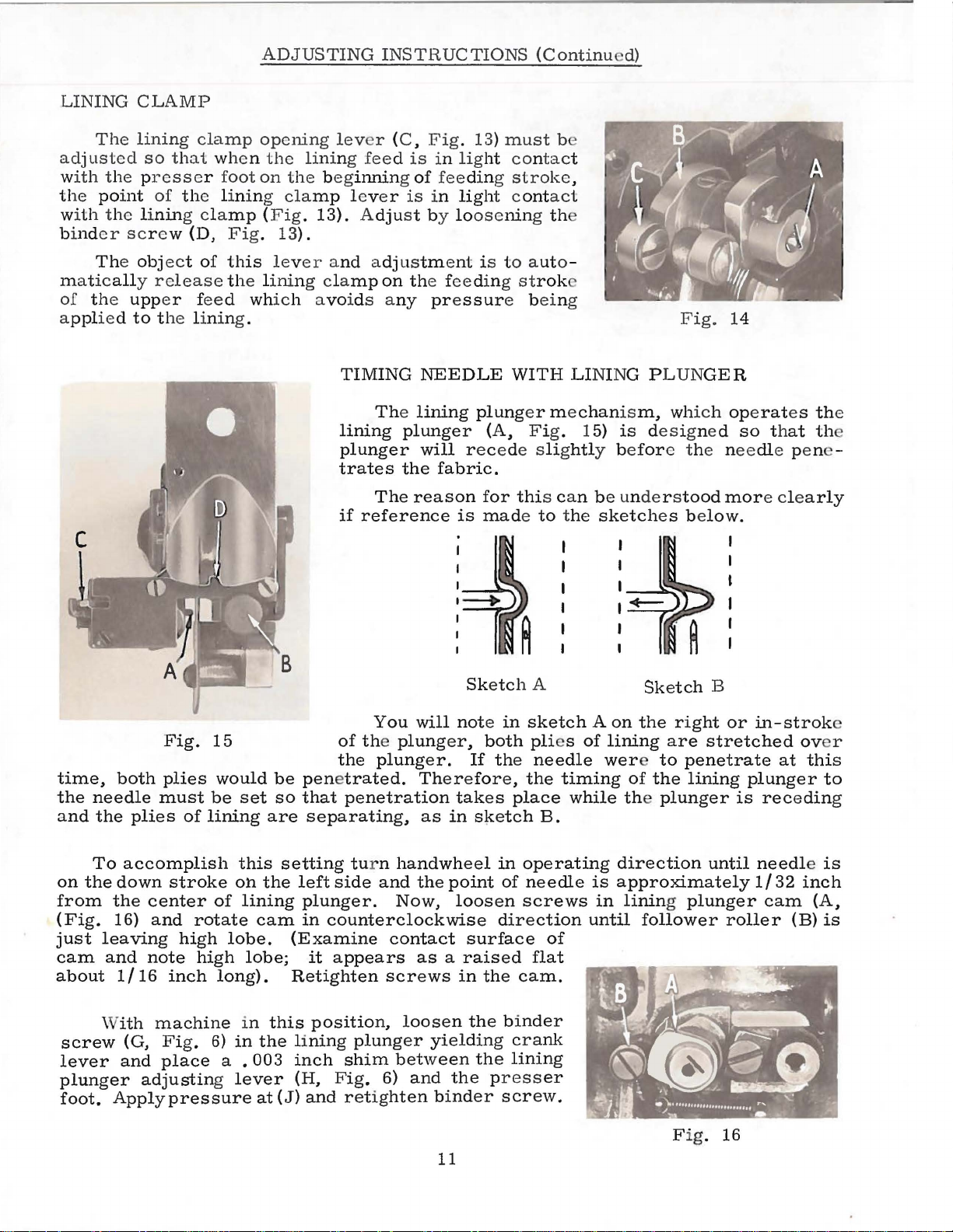
TIMING
The lining
lining
plunger
plunger
trates
if
the
The
reason
reference
Fig.
13)
in
lig
ht con
fee
ding
in
ligh
is
pressur
NEEDLE
plung
will
r ecede slig
fabric.
for
is
made to the
must
t c
tac
stroke
ontact
b
t
,
ning th
to aut
o-
e being
WITH LINING P
er
m e
chanism,
(A, Fig. 1
thi
s can
5}
htl
y be
be unde
is des
for
sketch
Fig.
LUN
14
GER
which ope
igne d
so that
e t he needl
r s
tood
more clearly
es be
low.
rat
es the
e pene -
th
time,
the
needle
and
the
To
on
the
from
(Fig.
just
leaving
cam
and
about
\
screw
lever
plunger
foot.
Fig.
both
plies
must
plies
of
lining
accomplish
down
the
16)
stroke
center
and
rotate
high
note
1/16
ith
(G,
and
high
inch
machine
Fig.
place
adjusting lever
Apply
pressure
15
would
be
set
this
oh
of
lining
lobe.
lobe;
long).
in
6)
in
a . 003
be
penetrated.
so
that
are
separating,
setting tur n
the
left
plunger.
cam
in
counterclockwise
(Examine
it
Retighten
this
position,
the
lining
inch
(H,
at
(J}
and
You
of the
the
plunger,
plunger.
penetration
handwheel
side
and
Now,
contact
appears
screws
loosen
plunger
shim
Fig.
between
6)
retighten
Sketch
will
note
both
If
Therefore,
takes
as
in
s~etch
the
point
loosen
surface
as a raised
in
the
the binder
yielding
the
and
the
binder
11
A
in
sketch A on
pli
the
needle
the
place
B.
in
operating
of
needle
screws
direction
of
flat
cam.
crank
lining
presser
screw.
es
of
lining
wer
timing
while the
is
in
until
Sketch
the
to
of
the
B
r i
ght
are
stretched
penetrate
lining
or
plunger
direction
until
approximately
lining plunger
follower
roller
Fig. 16
in-
strok
at
plunger
is
receding
needle is
1/32
cam
ov
this
inch
(B)
e
er
to
(A,
is
 Loading...