

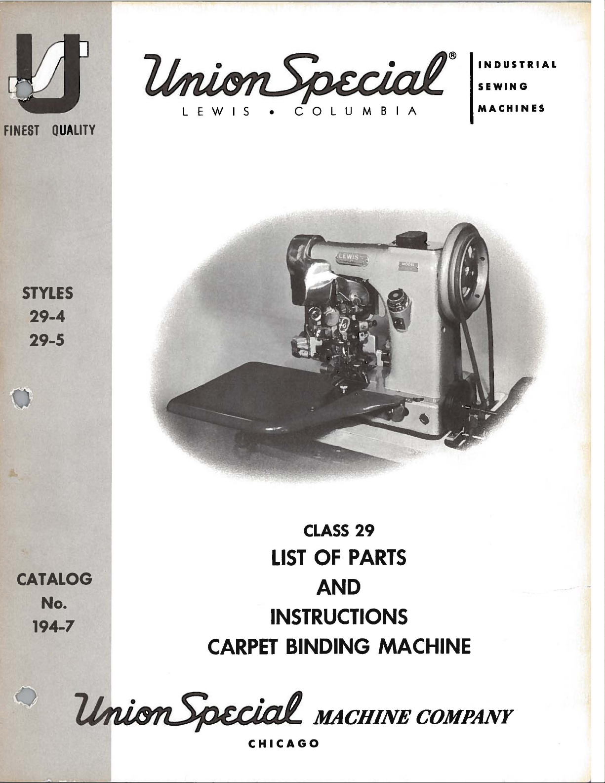
Lewis 29-4, 29-5 User Manual
®
INDUSTRIAL
SEWING
FINEST QUA
STYLES
29-4
29-5
LITY
L E
WIS
•
COLUMBIA
MACHINES
CATALOG
CLASS
LIST
OF
29
PARTS
AND
No.
INSTRUCTIONS
194-7
CARPET
CHICAGO
BINDING
MACHINE
FOREWORD
There
demand
greater
has
come
At
has
made
binding.
the
LEWIS
The
binding
81200
the
AZ.
Lewis
machine
The
mounted
powerful~
spring
gripping
has
by
the
variety
into
first~
it
Our
Carpet
first
to
the
The
Carpet
for
LEWIS
on
consisting
pressed
the
with a feeding
The
carpet
sewing
carpet
in
the
re-rolled
continues
the
LEWIS
binding
the
edge
and
been a great
people
of
sizes
wide
these
necessary
attention
Binding
operation
carpet.
binding
binding
Class
top
of
rolls
binding
rate
is
rolled~
of
along
Carpet
has
been
the
opposite
for
to
use
broadloom
carpets
for
was
in
This
is
Binding
carpets
29
the
table~
of
the
directly
and
carpet~
of
four
binding
on
Binding
stretched
change
rugs
be
were
the
that
carried
bound
carpet
called
Machine.
sewing
operation
then
carried
Machine
results
machines
requiring
two
top
rotary
under
pull
{4)
stitches
placed
to
the
on
the
conveyor~
Machine
over
edge
is
bound.
in
the
more
by
carpets
by
dealers
to
this
binding
up
to
the
in
prompt
are
the
top
the
carpet~
per
the
carpet
the
carpet
nearly
the
carpet
that
hand~
necessity
on
is
usually
and
backing
industry
fit
can
be
but
to
speed
carpets
over
of
the
room~
dealers.
cut
the
and
done
the
edge
the
deliveries
45
no
hole
feeds
feeds.
inch
degree
with
lying
at
for
1400
the
very
The
right-hand
powerful
on
R.
conveyor -about
on
the
and
and
carpet
the
is
Union
corner
pulled
and
Special
along
blindstitched~
in
recent
which
With
to
any
demand
up
their
this
size.
for
methods
resulted
is
to
sew
on a Union
and
is
carpet.
and
satisfied
machines
machine.
coarse
teeth
top
a
conveyor~
P.
M.
18
inches
Style
of
the
carpet
on
the
years
through
necessitates
change
faster
service
of
in
our
producing
one
edge
Special
blindstitched
Using
the
customers.
that
The
feed
is
acting
against
rotating
by
the
machine
is
unrolled
81200 AZ;
is
then
conveyor;
the
carpet
a
there
carpet
of
the
Style
by
LEWIS
are
very
feeds~
for
the
placed
after
is
The
machine
edge~
carpet
the
including
The
machine
binding
needle
thread.
and
winding a coarse
Machine.
equipped
More
with
oil
is
equipped
stretching
will
handle
No.
30
thread
production
pads
for
device
threads
It
is
recommended
or
finer
on
paper
can
lubricating
with a device
for
laying
as
coarse
for
the
bobbin.
bobbins
be
gained
the
by
thread.
2
for
rolling
the
binding
as
that
No. 16
suitable
using
No.
Some
for
these
the
binding
tightly
16
and
to
No.
thread
the
LEWIS
bobbins.
Engineering
up
and
in
place.
as
fine
as
24
thread
be
manufacturers
Carpet
The
machine
Department
over
the
finest
used
Binding
the
in
are
is
Catalog
No.
INSTRUCTIONS
FOR
194-7
The
furnished
ADJUSTING
LIST
29-4
parts
at
listed
list
First
AND
OF
Styles
in
prices
OPERATING
PARTS
29-5
this
for
Edition
catalo
repairs
g
are
only.
Copyri
g
ht
1965
by
Union
Rights
Special
Reserved
Machine
in
All
Countries
MACHINE COMPANY
INDUSTRIAL
Printed
September~
1965
SEWING
CHICAGO
in
3
MACHINES
U.S.A.
Co.
IDENTIFICATION
OF
MACHINES
Each
of
machines,
The
below
This
herein.
are
taken
direction
High
Machine.
the
line
operated
4
1/4
29-4
carpets
29-5
and
mechanism
hard
plunger
has a contoured
Standard
Union
serial
the
plunger
catalog
All
of
Production,
of
for
inches.
For
Same
also
to
is
references
from
the
handwheel
Needle
feed.
inserting
the
second
or
rugs.
as
29-4,
reduces
sew
which
needle
Special
stamped
number
regulator.
applies
the
operator's
Two
travels
Calibrated
and
operation
Standard
except
marking
greatly
carpets.
minimizes
top
Type
Lewis
in
of
to
reduces
with a deeper
machine
the
style
each
APPLICATION
specifically
direction,
is
DESCRIPTION
Thread,
from
removing
This
29-127.
machine
position
away
right
penetration
of
blindstitching
needle
wider
on
carpet
new
needle
carries
plate
to
such
from
feed
the
Single
to
adjustment.
work.
Type
wheels,
the
mechanism
blunting.
a
style
on
the
front
is
stamped
OF
CATALOG
the
Standard
as
right
while
OF
left
carpet
backing breakage
notch,
seated
operator.
MACHINES
Curved
and
Maximum
carpet
29-137.
which
backing.
The
to
number,
of
in
Styles
and
at
Needle,
penetrates
Work
work
binding
increases
produces
plunger
greatly
the
column.
the
base,
of
left,
front
the
machine.
Lockstitch,
at
support
space
A
new
and
a
dwell
is
reduce
which,
machines
an
to
the
cracking on some
smaller
in
this
class
on
the
right
as
listed
and
back,
Blindstf1:ch
angle
plate.
to
right
the
under side
feeding power
plung
er
{paus
in
needle blunting.
etc.
Operating
of
45
Treadle
of
needle
driving
e )
of
ar ea
side
,
to
of
the
and
Use
only
"LEWIS"
The
by
this
The
Selection
material
ood
a g
When sewin
point.
To
sample needle,
the
label.
on
the
type
catalog are g
following
used.
stitch
have needle
formation.
A comple
genuine
shank.
number
types
of
proper
Thread
g,
immediately
or
the
NEEDLES
Union
of
iven
Needle
orders promptly
te
order
Special
the
needles
in
the
and
sizes
Type
29-127
29-136
29-137
needle size
should pass freely through t
Type numb
would read:
Lewis needle
recommend
machine
are
discard any needle whi
er s
styl
availabl
Size
•
070
•
060
•
070
is
det
and accurately filled,
hould
"100
s.
They
ed
for
each
e description.
e:
Blade
Uniform
Ball ey
all
ey e
B
er m
ined by size
he
needle eye in
ch
be f
orwarded
Nee
dle
s,
are stamped
style of
e
of
thread
may
have a hook
an
em
. Us e the description
Typ
e 29- 137".
with the
mach
or der
ine cov
and weight
pty
contain
to
ed
word
er ed
produc
or blu
er,
of
e
nt
a
on
4
ADJUS
CHA
TING
NGI
INSTRUCTIONS
NG NEEDLES
When
carrier
improper
six
machine
table.
hole
removing
with
operation.
To
gasoline
allow
e
xposed
as far
Immediately dis
needl
Class
holes.
to
This
will
To
vaseline.
remov
have
th
protect the
e
or petrol
the
thread
part
ch
ang
ing needle. make
as
it will
e pe
netrat
29 m achines
two
to per
table. Set m achine from
is the m ost c
to
be
e f
oot
or
which
T
ake off the a
this cov
to remove th
to pass ov
s.
go. and tight
card any
ion wi
are
mit the be
onvenient position for
drill
ed
load
ing work.
machi
er the t
ne
must
luminu
er the
needle
ll res
set on
lt
wh
en
fro
m r usting
be c
aref
m head
ake
- up (H.
e gr
su
r e that the
en cla
which may have a hooked
ult
SETTI G
a s
to operate from
using treadle
ully
ease from the
hook freely
mp scr
.
olid board. and
four to
wh
wipe
cov
er
by loo
Fig
.
.
needle
ew completely.
UP
the
five
inches
handling the
for
ile
in transit.
d off
1)
Also wipe
mu
befo
sen
st
hook
is inserted in
or
it
is
only necessary
transmitter
from the
work.
dr
opping
re the
ing
thumb scre
be
at its
and
off
low
all par
bobbin cas
foot,. needle
blunt
and
front edge
An
er rolle
ts
machine
w (H.
lowest
the nee
ed poi
four
are
point.
nt..,
to
to
additional
r.
covered
is put
Fig. 13
e.
so
and
dle
bore
bolt
of
the
when
Use
as
other
as
in
).
to
Fig
. 1
•
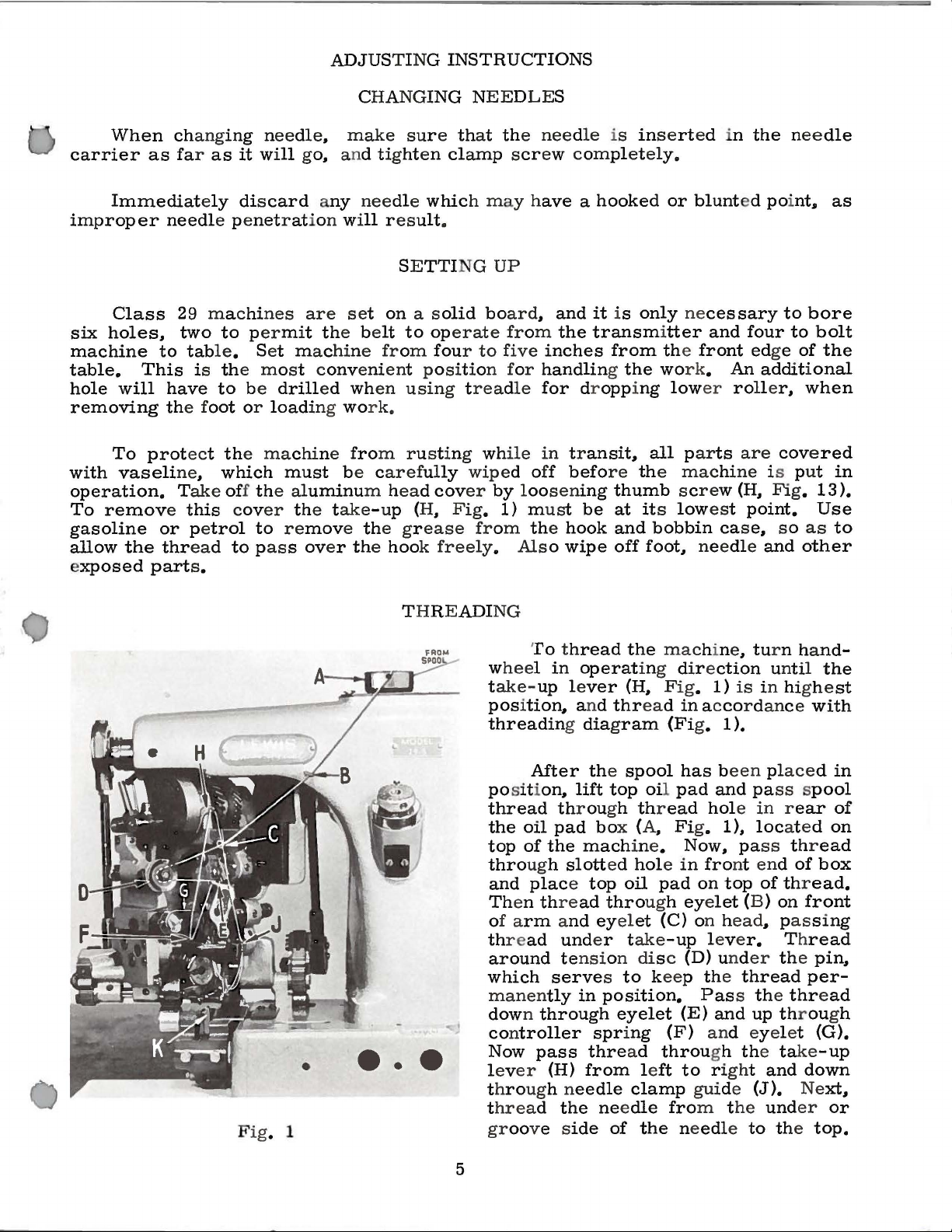
THREADING
•••
To thread
w
heel in
t
ake-
pos
ition,. and
threading diagram
After the
posit
thread
the
oil
top
of
through
and
place top
Th
en thre
of a
rm and eyel
th
r e
ad
around tensi
which
manen
down through
controller
Now
lev
er
throug
t
hread the nee
groove s
operat
up lever
ion,.
lift
throu
pad box (A. Fig.
the
slott
ad
und
serves to keep the thread
tly
in
pass
(H)
h n
eedle
ide
the
ing dir e
(H,.
thread
spool
top oil
gh thr
mach
ine.
ed
hole in
oil
through eye
et
er t
ake
on dis c (D) und
position.
eyelet
spring
thre
ad
from left
clamp
dle
of
the needle to the
mac
hine. tur n ha
ction
Fig
.
1)
in acco
(Fi
g. 1 ).
has been placed in
pad
and pass spool
ead
hole in rear
1).
Now. pass thr
fro
pad
on
top
let
(C) on h
-up
leve
Pass the thread
(E)
and
(F) and eyel et
throu
gh the take
to right and
gui
de
fro
m t
unt
is
in highe
r dance
loc
ated
nt end
(B )
ead
r.
he
of
of thr
on
,. pas
Th
er the pin,.
up through
(J).
und
er
nd-
il
the
with
ead
box
ead.
front
sing
read
per-
(G).
-up
down
Ne
xt,.
or
top.
st
of
on
5
THREADING
(Continued)
When
under
mend
To
to
the
One
loading
loaded
used
the
disc
loading
sew
in
needle
in
the
passing
the
take-up
that
the
avoid
Left"
of
the
tension
the
and
the
the
next
thread
lever
take-up
misunderstanding
we
have
the
characteristics
work
following
thread
into
disc
hook
material
carpet.
lever
Turn
inserted
the
located
manner:
thread
holder,
as
from
(H).
be
to
the
the
machine.
on
may
then
it
is
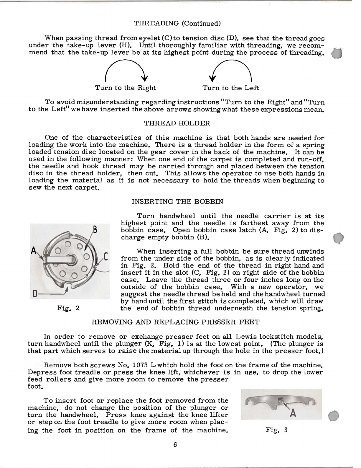
INSERTING
eyelet
Until
Right
the
When
not
thoroughly
at
its
regarding
above
THREAD
of
this
There
gear
one
be
carried
cut.
necessary
(C)to
highest
instructions
arrows
HOLDER
machine
is a thread
cover
end
This
THE
tension
familiar
point
showing
in
the
of
the
through
allows
to
BOBBIN
disc
during
Turn
is
back
carpet
the
hold
(D),
with
to
the
"Turn
what
that
both
holder
of
and
placed
operator
the
threads
see
threading,
the
process
Left
to
the
these
hands
in
the
the
is
completed
that
the
of
Right"
expressions
are
form
machine.
between
to
use
both
when
thread
we
threading.
and
needed
of a spring
and
the
beginning
goes
recom-
"Turn
mean.
It
can
run-off,
tension
hands
for
be
in
to
Fig.
In
order
turn
handwheel
that
part
which
R m
ove
Depress foot
feed
foot.
rollers
2
REMOVING
to
remove
until
serves
both
screws
treadle
and give
the
to
or
more
highest
bobbin
charge
from
in
Fig.
insert
case.
outside
suggest
by
hand
the
or
exchange
plunger
raise
No.
1073
press
room
Turn
case.
empty
When
the
it
Leave
the
until
end
AND
(K,
the
the
knee
to
handwheel
point
under
2.
in
of
of
REPLACING
material
Lwhich
and
Open
bobbin
inserting
side
Hold
the
slot
the
the
bobbin
needle
the
first
bobbin
presser
Fig.
remove
1)
hold
lift,
the
thread
up
whichever
until
the
needle
bobbin
(B).
a
full
of
the
end
(C,
thread
stitch
thread
PRESSER
feet
is
at
through
the
the
presser
the
case
bobbin
bobbin,
of
the
Fig.
2)
three
case.
be
held
is
underneath
on
all
the
lowest
the
foot
on
is
needle
is
farthest
latch
thread
on
or
With a new
and
completed,
FEET
Lewis
hole
the
in
be
sure
as
is
right
four
the
the
point.
in
frame
use,
(A,
side
inches
lockstitch
the
to
carrier
away
Fig.
thread
clearly
in
right
handwheel
which
tension
(The
presser
of
drop
from
2)
indicated
hand
of
the
long
operator,
will
plunger
the
machine.
the
is
at
the
to
dis-
unwinds
and
bobbin
on
the
we
turned
draw
spring.
models,
foot.)
lower
its
is
To
machin
turn
or
step
ing
the
insert
e,
the
handwheel.
on
foot
do
the
foot
not
foot
in
position
or
replace
change
Press
treadle
the
to
on
the
foot
position
knee
give
the
against
more
frame
removed
of
the
the
room
of
the
6
from
plunger
knee
when
lifter
plac-
machine.
the
or
Fig.
3
REMOVING
AND
REPLACING
PRESSER
FEET
(Continued)
Replace
(D,
Fig.
bobbin
A
C
both
gib
hook.
turn
case
Fig.
screws
After
(Fig.
and
2)
in
retainer.
4
removing
6).
tighten
the
(A,
This
the
bobbin
This
the
sary
case
cannot
operate.
bobbin
likely
bobbin
it
previously.
its
Fig.
gib,
releases
two
screws
case
is
lowest
5)
fits
holds
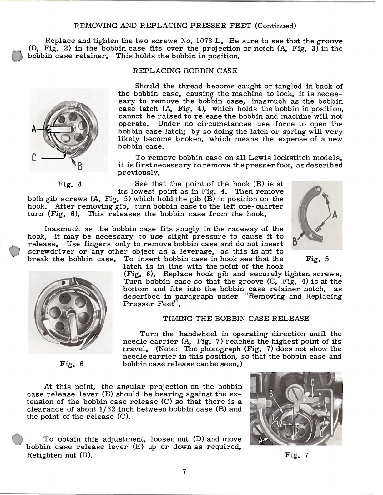
REPLACING
Should
bobbin
to
remove
latch
be
case
become
case.
To
remove
first
necessary
See
that
which
turn
bobbin
the
over
the
bobbin
the
case,
(A,
raised
Under
latch;
the
point
hold
bobbin
No.
1073
the
BOBBIN
thread
causing
the
Fig.
broken,
bobbin
the
4),
to
release
no
circumstances
by
to
point
as
in Fig.
gib
case
case
L.
projection
in
position.
CASE
become
the
bobbin
which
the
so
doing
which
case
remove
(B)
to
of
the
from
on
the
4.
in
left
Be
sure
or
caught
machine
case,
holds
bobbin
the
latch
means
all
Lewis
the
presser
hook
Then
position
one-
the
hook.
to
see
notch
inasmuch
use
(B)
remove
quarter
or
tangled
to
the
bobbin
and
force
or
the
lockstitch
is
on
the
(A,
lock,
expense
foot,
at
that
the
Fig.
it
as
the
in
machine
to
spring
as
groove
3)
in
the
in
back
is
neces-
bobbin
position,
will
not
open
will
of a new
described
the
very
models,
A
of
Inasmuch
hook,
release.
screwdriver
break
case
tension
clearance
the
it
the
At
release
point
Fig.
this
of
may
Use
bobbin
point,
the
of
about
of
the
as
be
fingers
or
any
6
lever
bobbin
release
the
bobbin
necessary
only
other
case.
the
(E)
1/32
To
latch
(Fig.
Turn
bottom
described
Presser
needle
travel.
needle
bobbin
angular
should
case
inch
(C).
case
to
to
remove
object
insert
is
6).
bobbin
Turn
carrier
case
projection
be
release
between
fits
snugly
use
slight
bobbin
as a leverage,
bobbin
in
line
with
Replace
case
and
fits
into
in
~aragraph
Feet'
carrier
(Note:
bearing
•
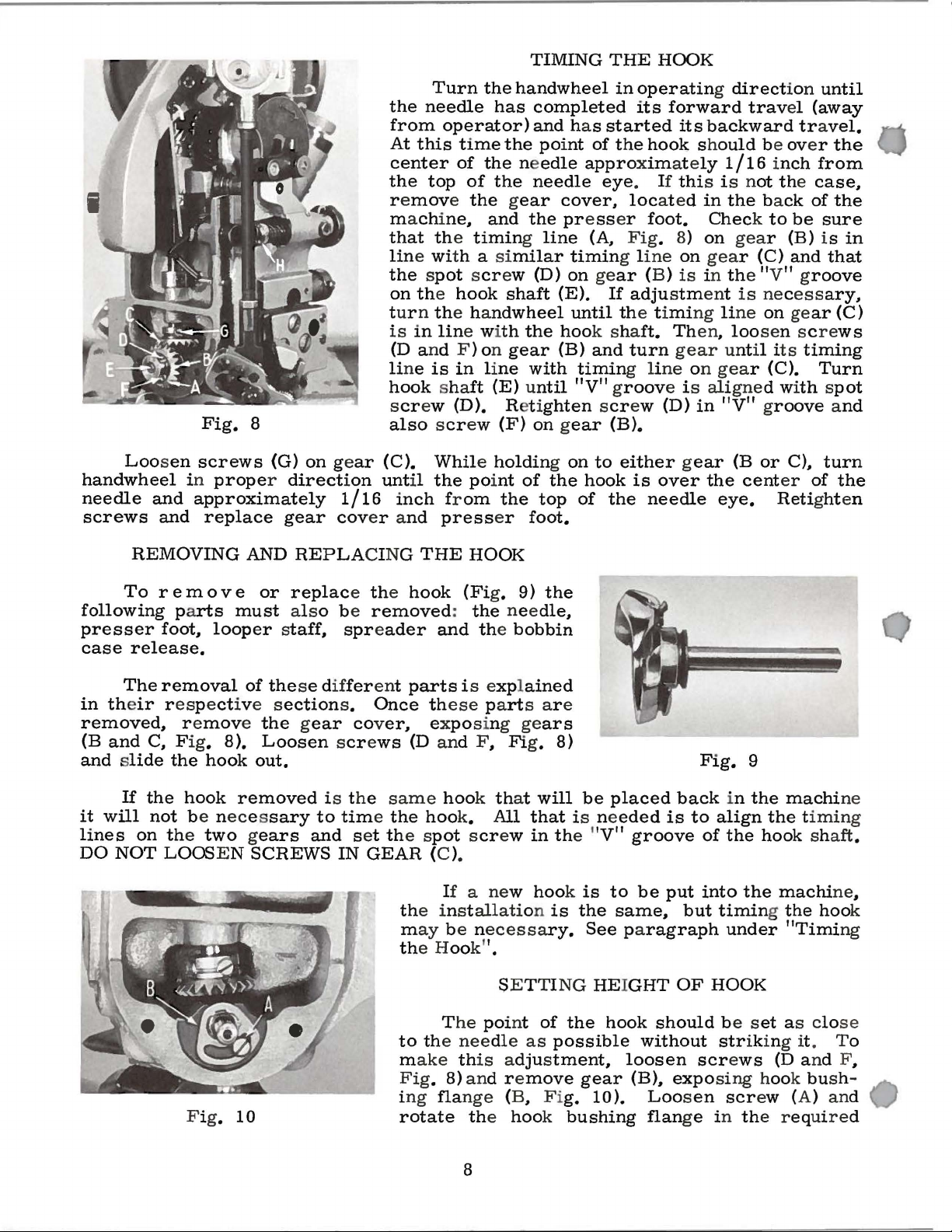
TIMING
the
handwheel
(A,
The
in
release
(C)
so
bobbin
this
against
that
in
the
pressure
case
case
in
the
hook
so
that
the
THE
on
BOBBIN
Fig.
can
case
7)
photograph
position,
be
the
the
there
(B)
raceway
to
and
do
as
this
hook
point
gib
and
the
bobbin
under
in
operating
reaches
seen.)
bobbin
ex-
is
and
of
cause
not
insert
is
apt
see
that
of
the
securely
groove
case
"Removing
CASE
the
(Fig.
so
that
a
the
it
to
to
the
hook
tighten
(C,
Fig.
retainer
and
RELEASE
direction
highest
7)
does
the
bobbin
Fig.
screws.
4)
is
notch,
Replacing
until
point
not
show
case
at
of
5
the
as
the
its
the
and
To
bobbin
Retighten
obtain
case
nut
this
release
(D).
adjustment,
lever
(E)
loosen
up
or
nut
down
7
(D)
and
as
required.
move
Fi
g. 7
TIMING
THE
HOOK
Loosen
handwheel
needle
screws
and
and
Fig.
screws
in
8
(G)
proper direction
approximately
replace
gear
on gear
1/16
cov
Turn
the
needle
from
At
this
center
the
top
r e
move the gear
machine~
that the
line wi
the
operator)
time
of
the needle
of
timing line
th a similar
the spot scr
on the
hook
tur n the ha
is
in
lin
e wi
(D
and F ) on
li
ne
is
in
line
hook
sha
ft
screw (D). Ret i
also scr
(C).
until
ew
While holding on
the poi
inch from
er a
nd
press
handwheel
has
completed
and
the poi
the
needle
and
the presser
ew (D)
shaft
ndwheel
th
the
gear
with
(E) until
ghten scr
(F)
on gear
nt
of
the
top
er
foot.
in
operating direct
its
forward
has
started
nt
of
the
approxim
eye
cover~
loc
its
hook should
at e
ly
.
If
thi
s i s n
ated
in
foot.
(A
Fig
. 8)
1
timing li
on gear
(E).
If
ne
(B) is in the "V" g
adjustment
on
on
until the timing line
hoo
k sha
(B)
and
timing li
"V" groov
ft.
Then~
turn
gear until its
ne
on
e i s ali
ew (D)
in
(B).
to
either gear
the
hook
of
the
is
over
needle
ion
until
trav
el
(away
backward tra
be over
1/16 inch
ot the
the back
Check to
gea
r (B) i s
gea
r (C)
from
case~
of
be
and
roove
is
necess
on gear
loosen screws
timing
gea
r (C).
gne
d wi
Turn
th spot
"V" groove and
(B
or
C)1 turn
the
cent
er
of
eye.
Retight
vel.
the
the
sure
in
that
ary~
(C)
the
en
REMOVING
To r em
following parts
presser
case
in the
removed~
(B
and
and slide
it
will
lines
DO
NOT
foot~
release.
The
removal
ir respect
r e
C~
Fig. 8).
the
If
the
hook
not
be neces
on the
LOOS E N
move the gear
hook
two gears
AND
o v e
must
looper
of
ive s
removed
REPLA
or
replace the hook
also be
CING
removed
staff1 spreader
the
se different
ection
s.
cover,
Loosen screws
out.
is the
sary
SCREWS
to
time the
and
IN
set the s
GEAR
THE
HOOK
(Fi
:
the
g. 9)
nee
and the
parts
i s expl
Once these part
exposing gears
(D and F1 Fi
same
hook th
hoo
k.
pot scr
All
ew
(C ).
If
a new
th
e inst
m
ay
th
e Hook"
be n
allati
ecess
.
SETTI NG
the
dle
bobbin
ained
s ar e
g.
8)
at
will
that
in the "
hook is
on
is
ary.
1
be
placed
is ne
eded
V"
groove
to
be
the
same1 but
See paragraph
HEIGHT
back
is
put
OF
Fig.
to
in
align
of
the
into
9
the
the
timing the
under
HOOK
machi
the timing
hook shaft
machi
ne
hoo
"Timi
ng
ne
.
1
k
T
he
poi
nt
of
Fig.
10
to the
m
Fig
ng
i
rotate
needle
as
possible
ake this adjustment1 loosen
. 8) and r e
fla
nge
move
(B1 Fi
g.
the hook bushing
8
the
gear
hook
should
without
be s
str
screws
(B)1 exposing hook bu
10).
Loosen
flan
scr
ge in the required
et
as close
iking it. To
(D
and F
sh-
ew (A) and
1
SETTING
HEIGHT
OF
HOOK
(Continued)
direction
cannot
in
the
Replace
The
(H,
Fig.
set
sufficiently
make
needle
Fig.
more
against
so
very
grades
stitch
and
plunger,
this
The
11
tightly
as
to
little
The
or
spreader
to
position
be
turned
alternate
gear
needle
8)
to
adjustment
tension
bobbin
).
By
as
the
thread.
permit
resistance.
of
work
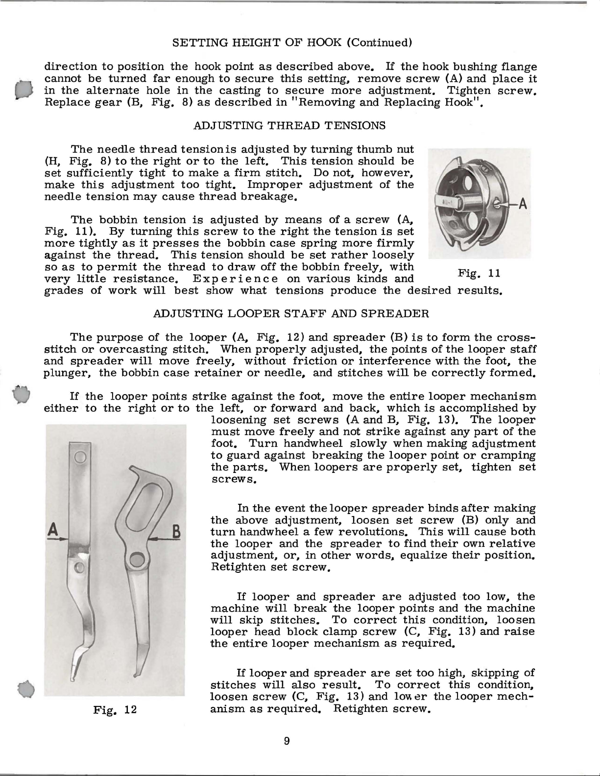
purpose
overcasting
the
bobbin
far
hole
(B,
Fig.
thread
the
right
tight
may
cause
tension
turning
it
presses
the
will
ADJUSTING
of
the
will
move
case
the
hook
enough
in
the
8)
as
ADJUSTING
tension
or
to
to
make a firm
too
tight.
thread
is
this
screw
the
This
thread
Ex
best
looper
stitch.
freely,
retainer
tension
show
point
to
secure
casting
described
is
adjusted
the
left.
Improper
breakage.
adjusted
to
bobbin
should
to
draw
p e r i
en
what
LOOPER
(A,
When
without
or
as
described
this
to
secure
in
"Removing
THREAD
by
This
stitch.
by
means
the
right
case
be
off
the
c e
on
tensions
STAFF
Fig.
properly
12)
friction
needle.
above.
setting,
more
TENSIONS
turning
tension
Do
not,
adjustment
of a screw
the
tension
spring
set
bobbin
various
and
adjusted,
rather
produce
AND
and
more
freely,
spreader
or
stitches
If
the
remove
adjustment.
and
thumb
should
however,
firmly
loosely
kinds
SPREADER
the
interference
screw
Replacing
nut
be
of
the
(A,
is
set
with
and
the
desired
(B)
is
points
will
hook
to
of
with
be
correctly
bushing
(A)
and
Tighten
Hook".
Fig.
results.
form
the
the
looper
the
flange
place
screw.
11
cross-
staff
foot,
formed.
it
the
either
A
If
the
to
Fig.
looper
the
right
12
points
or
to
B
strike
the
left,
loosening
must
foot.
to
guard
the
screws.
the
turn
the
adjustment,
Retighten
machine
will
looper
the
stitches
loosen
anism
against
move
parts.
In
above
handwheel a few
looper
If
skip
entire
If
the
or
forward
set
Turn
against
the
event
adjustment,
set
looper
will
stitches.
head
looper
looper
will
screw
as
required.
foot,
screws
freely
handwheel
When
the
and
the
or,
in
screw.
and
break
block
and
also
(C,
move
and
back,
(A
and
and
not
slowly
breaking
loopers
looper
spreader
other
spreader
the
To
clamp
mechanism
spreader
result.
Fig.
Retighten
are
loosen
revolutions.
words,.
looper
correct
screw
13)
the
entire
which
B,
strike
when
the
looper
properly
spreader
set
to
are
as
are
set
To
correct
and
loVI.
screw.
looper
is
accomplished
Fig.
against
find
equalize
points
this
(C,
required.
13).
making
point
binds
screw
This
their
adjusted
and
condition,
Fig.
too
high,
er
the
any
or
set,
after
(B)
will
own
their
too
the
13)
this
looper
mechanism
by
The
looper
part
of
the
adjustment
cramping
tighten
only
cause
relative
position.
low,
machine
and
skipping
condition,
set
making
and
both
the
loosen
raise
mech-
of
9
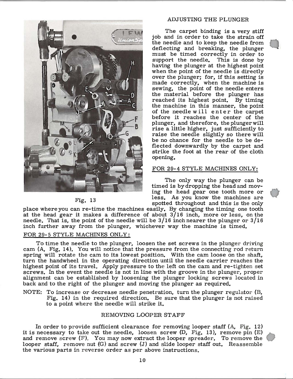
ADJUSTING
The
carpet
job
and
in
the
needle
deflecting
must
support
having
when
over
made
sewing,
the
reached
the
of
before
plunger,
rise a little
raise
be
flected
strike
opening.
be
the
the
the
correctly,
material
machine
the
needle
it
the
no
chance
downwardly
the
timed
the
point
plunger;
the
its
and
order
and
and
needle.
plunger
of
point
before
highest
in
w i 11
reaches
therefore,
higher,
needle
for
foot
THE
binding
to
take
to
keep
breaking,
correctly
at
the
needle
for,
when
of
the
point.
this
at
manner,
en
the
just
slightly
the
by
the
PLUNGER
is a very
the
the
needle
the
in
This
the
if
the
needle
rear
is
highest
is
this
setting
the
machine
needle
plunger
By
t e r
the
center
the
plunger
sufficiently
so
there
to
the
carpet
of
strain
from
plunger
order
done
point
directly
enters
timing
the
point
carpet
of
be
the
cloth
stiff
off
to
by
is
is
has
the
will
to
will
deand
place
at
needle.
inch
FOR 2 9-5 STYLE
cam
spring
turn
highest
screws.
alignment
back
NOTE:
the
further
To
(A,
the
and
where
head
you
gear
That
time
will
point
To
Fig.
to a point wher e the ne
is,
away
the
Fig.
14).
rotate the cam
handwhe
of its trave
In
the eve
can
be
to
the rig
incre
14)
Fig.
can
the
needle
el
ase
in
13
re-time
it
makes
point
from
MACHINES
to
You
will notice that
in
the
l.
nt the
established
ht
needle
of the
or decrease
the required
the
machines
a
difference
of
the
needle
the
plunger,
ONLY:
the
plunger,
to
its
lowest
operating direction
Apply pre
is
by
loosening
plung
er
ne
direction.
edl
e will s
not
and
edle
ssure
in
will
whichever
loosen
the
moving
penetration,
FOR
timed
ing
less.
spotted
easily.
of
about
be
3/16
the
pressure
position.
until
to the left
line
with
the
Be
trike
it.
29-4
The
is
the
As
throughout
By
3/16
inch
way
set
from
With
the
the
plunger
the
plunger
sure
STYLE
only
by
head
changing
screws
on
groove
turn
that
way
dropping
gear
you
know
inch,
nearer
the
machine
the
the
cam
needle
the
cam
in the
locking screw
as
the
the
MACHINES ONLY:
the
plunger can
the
head and
one
tooth
the
machin
and
this
the
timing one tooth
more
in
connectin
carrier reaches
required.
plunger regulato
plunger
or less
the
plunger or
is
the
plunger driving
loose
and
re-tigh
plun
more
es are
is the
, on
tim
ed.
g r
od
r etur n
on the sha
t en s
ger, proper
s located
is
not
r aised
be
mov-
or
only
the
3/16
ft,
the
et
in
r (B,
RE
In
it
is
necessary
and
remove scr
looper
the
various
order
staff,
to
r e
parts
pr ovide s
to take
ew (F ).
mov
e n
ut
in rever
MOVING
ufficient clearance
out the needl
You may now extract the
(G)
and screw (J) and slide
se
ord
er a s p
LOOPER
e, loos
er above instruction
10
STAFF
for
removing looper staff
en screw
looper
(D, F ig. 13
spreader.
looper staff
s.
(A,
Fig.
),
remove pi
To remove the
out. Reassemble
12)
n (E)
 Loading...