

Page 1
®
INDUSTRIAL
SEWING
FINEST QUA
STYLES
29-4
29-5
LITY
L E
WIS
•
COLUMBIA
MACHINES
CATALOG
CLASS
LIST
OF
29
PARTS
AND
No.
INSTRUCTIONS
194-7
CARPET
CHICAGO
BINDING
MACHINE
Page 2
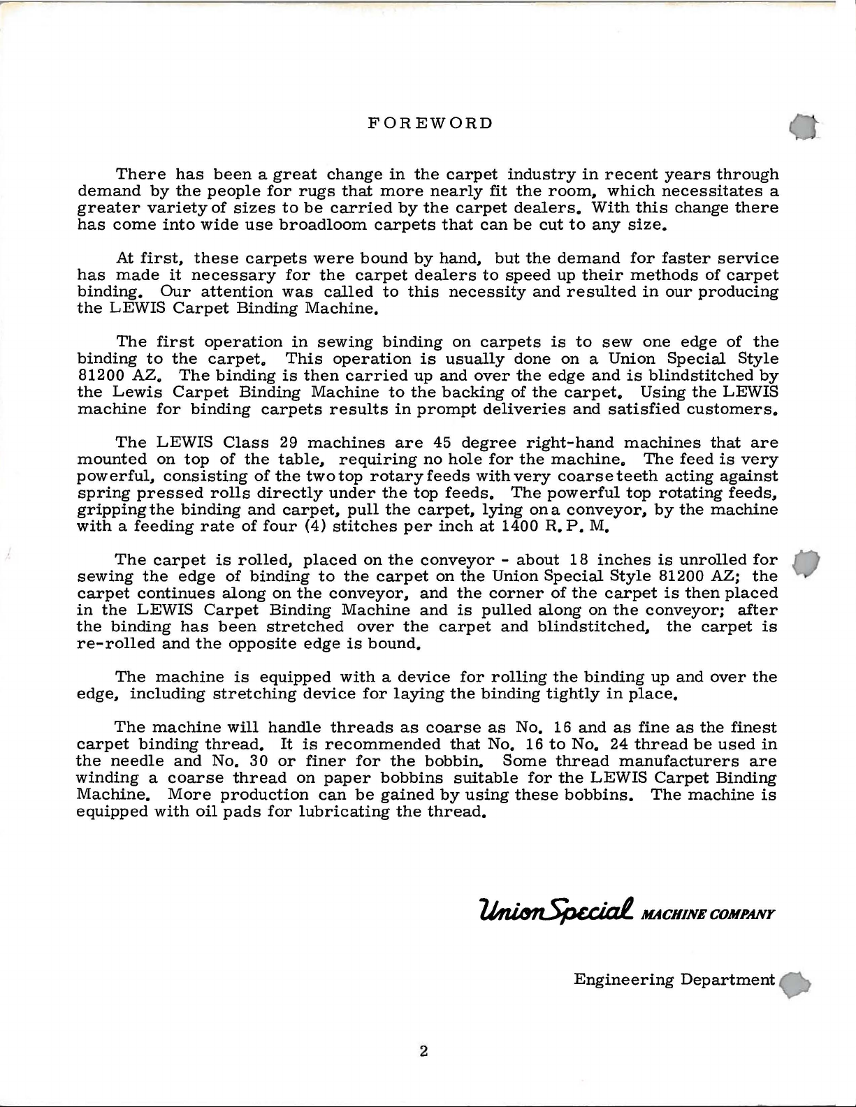
FOREWORD
There
demand
greater
has
come
At
has
made
binding.
the
LEWIS
The
binding
81200
the
AZ.
Lewis
machine
The
mounted
powerful~
spring
gripping
has
by
the
variety
into
first~
it
Our
Carpet
first
to
the
The
Carpet
for
LEWIS
on
consisting
pressed
the
with a feeding
The
carpet
sewing
carpet
in
the
re-rolled
continues
the
LEWIS
binding
the
edge
and
been a great
people
of
sizes
wide
these
necessary
attention
Binding
operation
carpet.
binding
binding
Class
top
of
rolls
binding
rate
is
rolled~
of
along
Carpet
has
been
the
opposite
for
to
use
broadloom
carpets
for
was
in
This
is
Binding
carpets
29
the
table~
of
the
directly
and
carpet~
of
four
binding
on
Binding
stretched
change
rugs
be
were
the
that
carried
bound
carpet
called
Machine.
sewing
operation
then
carried
Machine
results
machines
requiring
two
top
rotary
under
pull
{4)
stitches
placed
to
the
on
the
conveyor~
Machine
over
edge
is
bound.
in
the
more
by
carpets
by
dealers
to
this
binding
up
to
the
in
prompt
are
the
top
the
carpet~
per
the
carpet
the
carpet
nearly
the
carpet
that
hand~
necessity
on
is
usually
and
backing
industry
fit
can
be
but
to
speed
carpets
over
of
the
room~
dealers.
cut
the
and
done
the
edge
the
deliveries
45
no
hole
feeds
feeds.
inch
degree
with
lying
at
for
1400
the
very
The
right-hand
powerful
on
R.
conveyor -about
on
the
and
and
carpet
the
is
Union
corner
pulled
and
Special
along
blindstitched~
in
recent
which
With
to
any
demand
up
their
this
size.
for
methods
resulted
is
to
sew
on a Union
and
is
carpet.
and
satisfied
machines
machine.
coarse
teeth
top
a
conveyor~
P.
M.
18
inches
Style
of
the
carpet
on
the
years
through
necessitates
change
faster
service
of
in
our
producing
one
edge
Special
blindstitched
Using
the
customers.
that
The
feed
is
acting
against
rotating
by
the
machine
is
unrolled
81200 AZ;
is
then
conveyor;
the
carpet
a
there
carpet
of
the
Style
by
LEWIS
are
very
feeds~
for
the
placed
after
is
The
machine
edge~
carpet
the
including
The
machine
binding
needle
thread.
and
winding a coarse
Machine.
equipped
More
with
oil
is
equipped
stretching
will
handle
No.
30
thread
production
pads
for
device
threads
It
is
recommended
or
finer
on
paper
can
lubricating
with a device
for
laying
as
coarse
for
the
bobbin.
bobbins
be
gained
the
by
thread.
2
for
rolling
the
binding
as
that
No. 16
suitable
using
No.
Some
for
these
the
binding
tightly
16
and
to
No.
thread
the
LEWIS
bobbins.
Engineering
up
and
in
place.
as
fine
as
24
thread
be
manufacturers
Carpet
The
machine
Department
over
the
finest
used
Binding
the
in
are
is
Page 3
Catalog
No.
INSTRUCTIONS
FOR
194-7
The
furnished
ADJUSTING
LIST
29-4
parts
at
listed
list
First
AND
OF
Styles
in
prices
OPERATING
PARTS
29-5
this
for
Edition
catalo
repairs
g
are
only.
Copyri
g
ht
1965
by
Union
Rights
Special
Reserved
Machine
in
All
Countries
MACHINE COMPANY
INDUSTRIAL
Printed
September~
1965
SEWING
CHICAGO
in
3
MACHINES
U.S.A.
Co.
Page 4
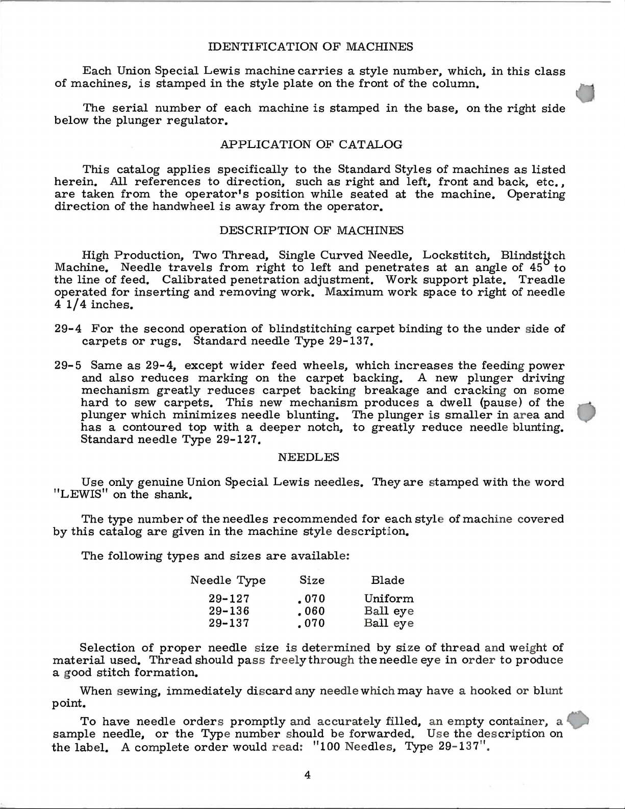
IDENTIFICATION
OF
MACHINES
Each
of
machines,
The
below
This
herein.
are
taken
direction
High
Machine.
the
line
operated
4
1/4
29-4
carpets
29-5
and
mechanism
hard
plunger
has a contoured
Standard
Union
serial
the
plunger
catalog
All
of
Production,
of
for
inches.
For
Same
also
to
is
references
from
the
handwheel
Needle
feed.
inserting
the
second
or
rugs.
as
29-4,
reduces
sew
which
needle
Special
stamped
number
regulator.
applies
the
operator's
Two
travels
Calibrated
and
operation
Standard
except
marking
greatly
carpets.
minimizes
top
Type
Lewis
in
of
to
reduces
with a deeper
machine
the
style
each
APPLICATION
specifically
direction,
is
DESCRIPTION
Thread,
from
removing
This
29-127.
machine
position
away
right
penetration
of
blindstitching
needle
wider
on
carpet
new
needle
carries
plate
to
such
from
feed
the
Single
to
adjustment.
work.
Type
wheels,
the
mechanism
blunting.
a
style
on
the
front
is
stamped
OF
CATALOG
the
Standard
as
right
while
OF
left
carpet
backing breakage
notch,
seated
operator.
MACHINES
Curved
and
Maximum
carpet
29-137.
which
backing.
The
to
number,
of
in
Styles
and
at
Needle,
penetrates
Work
work
binding
increases
produces
plunger
greatly
the
column.
the
base,
of
left,
front
the
machine.
Lockstitch,
at
support
space
A
new
and
a
dwell
is
reduce
which,
machines
an
to
the
cracking on some
smaller
in
this
class
on
the
right
as
listed
and
back,
Blindstf1:ch
angle
plate.
to
right
the
under side
feeding power
plung
er
{paus
in
needle blunting.
etc.
Operating
of
45
Treadle
of
needle
driving
e )
of
ar ea
side
,
to
of
the
and
Use
only
"LEWIS"
The
by
this
The
Selection
material
ood
a g
When sewin
point.
To
sample needle,
the
label.
on
the
type
catalog are g
following
used.
stitch
have needle
formation.
A comple
genuine
shank.
number
types
of
proper
Thread
g,
immediately
or
the
NEEDLES
Union
of
iven
Needle
orders promptly
te
order
Special
the
needles
in
the
and
sizes
Type
29-127
29-136
29-137
needle size
should pass freely through t
Type numb
would read:
Lewis needle
recommend
machine
are
discard any needle whi
er s
styl
availabl
Size
•
070
•
060
•
070
is
det
and accurately filled,
hould
"100
s.
They
ed
for
each
e description.
e:
Blade
Uniform
Ball ey
all
ey e
B
er m
ined by size
he
needle eye in
ch
be f
orwarded
Nee
dle
s,
are stamped
style of
e
of
thread
may
have a hook
an
em
. Us e the description
Typ
e 29- 137".
with the
mach
or der
ine cov
and weight
pty
contain
to
ed
word
er ed
produc
or blu
er,
of
e
nt
a
on
4
Page 5
ADJUS
CHA
TING
NGI
INSTRUCTIONS
NG NEEDLES
When
carrier
improper
six
machine
table.
hole
removing
with
operation.
To
gasoline
allow
e
xposed
as far
Immediately dis
needl
Class
holes.
to
This
will
To
vaseline.
remov
have
th
protect the
e
or petrol
the
thread
part
ch
ang
ing needle. make
as
it will
e pe
netrat
29 m achines
two
to per
table. Set m achine from
is the m ost c
to
be
e f
oot
or
which
T
ake off the a
this cov
to remove th
to pass ov
s.
go. and tight
card any
ion wi
are
mit the be
onvenient position for
drill
ed
load
ing work.
machi
er the t
ne
must
luminu
er the
needle
ll res
set on
lt
wh
en
fro
m r usting
be c
aref
m head
ake
- up (H.
e gr
su
r e that the
en cla
which may have a hooked
ult
SETTI G
a s
to operate from
using treadle
ully
ease from the
hook freely
mp scr
.
olid board. and
four to
wh
wipe
cov
er
by loo
Fig
.
.
needle
ew completely.
UP
the
five
inches
handling the
for
ile
in transit.
d off
1)
Also wipe
mu
befo
sen
st
hook
is inserted in
or
it
is
only necessary
transmitter
from the
work.
dr
opping
re the
ing
thumb scre
be
at its
and
off
low
all par
bobbin cas
foot,. needle
blunt
and
front edge
An
er rolle
ts
machine
w (H.
lowest
the nee
ed poi
four
are
point.
nt..,
to
to
additional
r.
covered
is put
Fig. 13
e.
so
and
dle
bore
bolt
of
the
when
Use
as
other
as
in
).
to
Fig
. 1
•
THREADING
•••
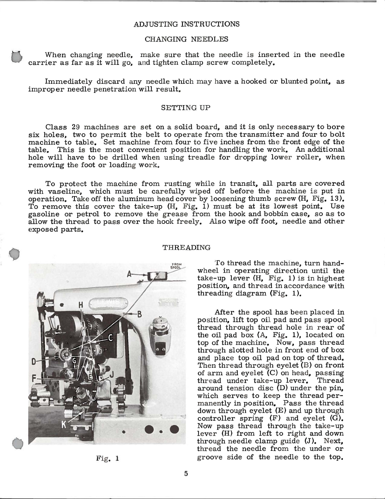
To thread
w
heel in
t
ake-
pos
ition,. and
threading diagram
After the
posit
thread
the
oil
top
of
through
and
place top
Th
en thre
of a
rm and eyel
th
r e
ad
around tensi
which
manen
down through
controller
Now
lev
er
throug
t
hread the nee
groove s
operat
up lever
ion,.
lift
throu
pad box (A. Fig.
the
slott
ad
und
serves to keep the thread
tly
in
pass
(H)
h n
eedle
ide
the
ing dir e
(H,.
thread
spool
top oil
gh thr
mach
ine.
ed
hole in
oil
through eye
et
er t
ake
on dis c (D) und
position.
eyelet
spring
thre
ad
from left
clamp
dle
of
the needle to the
mac
hine. tur n ha
ction
Fig
.
1)
in acco
(Fi
g. 1 ).
has been placed in
pad
and pass spool
ead
hole in rear
1).
Now. pass thr
fro
pad
on
top
let
(C) on h
-up
leve
Pass the thread
(E)
and
(F) and eyel et
throu
gh the take
to right and
gui
de
fro
m t
unt
is
in highe
r dance
loc
ated
nt end
(B )
ead
r.
he
of
of thr
on
,. pas
Th
er the pin,.
up through
(J).
und
er
nd-
il
the
with
ead
box
ead.
front
sing
read
per-
(G).
-up
down
Ne
xt,.
or
top.
st
of
on
5
Page 6
THREADING
(Continued)
When
under
mend
To
to
the
One
loading
loaded
used
the
disc
loading
sew
in
needle
in
the
passing
the
take-up
that
the
avoid
Left"
of
the
tension
the
and
the
the
next
thread
lever
take-up
misunderstanding
we
have
the
characteristics
work
following
thread
into
disc
hook
material
carpet.
lever
Turn
inserted
the
located
manner:
thread
holder,
as
from
(H).
be
to
the
the
machine.
on
may
then
it
is
INSERTING
eyelet
Until
Right
the
When
not
thoroughly
at
its
regarding
above
THREAD
of
this
There
gear
one
be
carried
cut.
necessary
(C)to
highest
instructions
arrows
HOLDER
machine
is a thread
cover
end
This
THE
tension
familiar
point
showing
in
the
of
the
through
allows
to
BOBBIN
disc
during
Turn
is
back
carpet
the
hold
(D),
with
to
the
"Turn
what
that
both
holder
of
and
placed
operator
the
threads
see
threading,
the
process
Left
to
the
these
hands
in
the
the
is
completed
that
the
of
Right"
expressions
are
form
machine.
between
to
use
both
when
thread
we
threading.
and
needed
of a spring
and
the
beginning
goes
recom-
"Turn
mean.
It
can
run-off,
tension
hands
for
be
in
to
Fig.
In
order
turn
handwheel
that
part
which
R m
ove
Depress foot
feed
foot.
rollers
2
REMOVING
to
remove
until
serves
both
screws
treadle
and give
the
to
or
more
highest
bobbin
charge
from
in
Fig.
insert
case.
outside
suggest
by
hand
the
or
exchange
plunger
raise
No.
1073
press
room
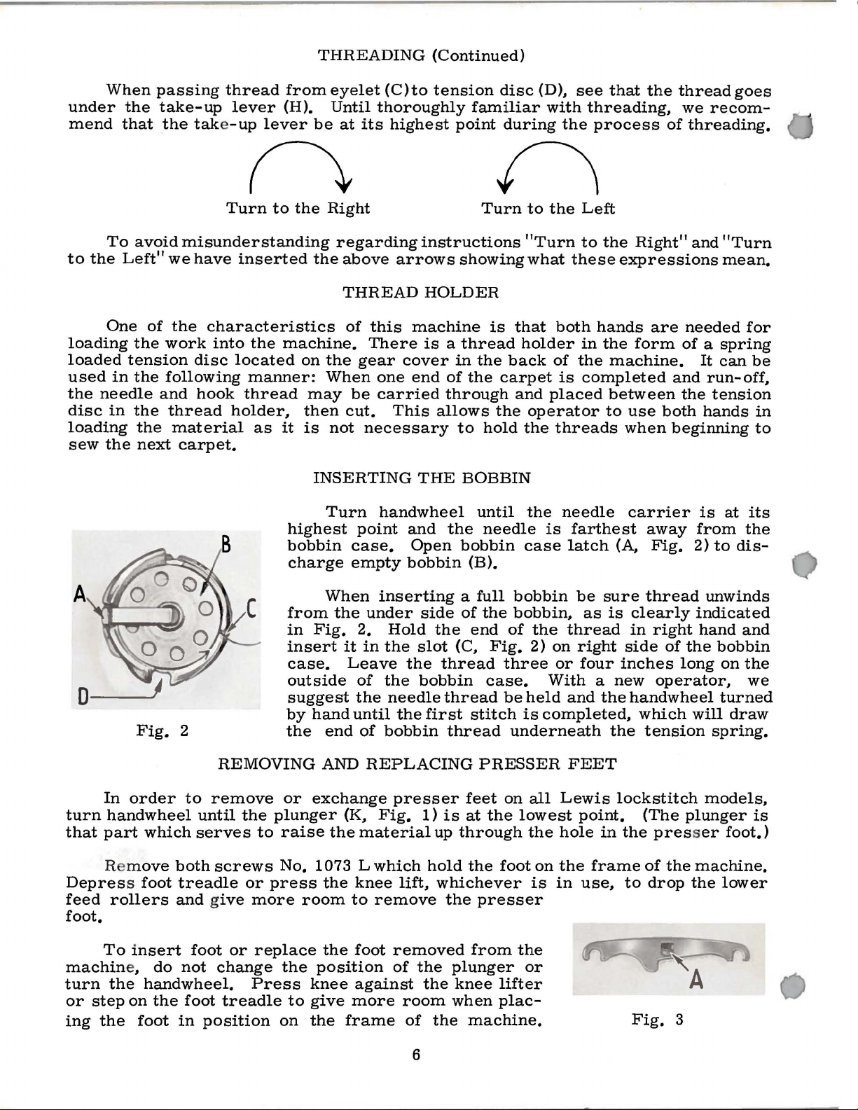
Turn
case.
empty
When
the
it
Leave
the
until
end
AND
(K,
the
the
knee
to
handwheel
point
under
2.
in
of
of
REPLACING
material
Lwhich
and
Open
bobbin
inserting
side
Hold
the
slot
the
the
bobbin
needle
the
first
bobbin
presser
Fig.
remove
1)
hold
lift,
the
thread
up
whichever
until
the
needle
bobbin
(B).
a
full
of
the
end
(C,
thread
stitch
thread
PRESSER
feet
is
at
through
the
the
presser
the
case
bobbin
bobbin,
of
the
Fig.
2)
three
case.
be
held
is
underneath
on
all
the
lowest
the
foot
on
is
needle
is
farthest
latch
thread
on
or
With a new
and
completed,
FEET
Lewis
hole
the
in
be
sure
as
is
right
four
the
the
point.
in
frame
use,
(A,
side
inches
lockstitch
the
to
carrier
away
Fig.
thread
clearly
in
right
handwheel
which
tension
(The
presser
of
drop
from
2)
indicated
hand
of
the
long
operator,
will
plunger
the
machine.
the
is
at
the
to
dis-
unwinds
and
bobbin
on
the
we
turned
draw
spring.
models,
foot.)
lower
its
is
To
machin
turn
or
step
ing
the
insert
e,
the
handwheel.
on
foot
do
the
foot
not
foot
in
position
or
replace
change
Press
treadle
the
to
on
the
foot
position
knee
give
the
against
more
frame
removed
of
the
the
room
of
the
6
from
plunger
knee
when
lifter
plac-
machine.
the
or
Fig.
3
Page 7
REMOVING
AND
REPLACING
PRESSER
FEET
(Continued)
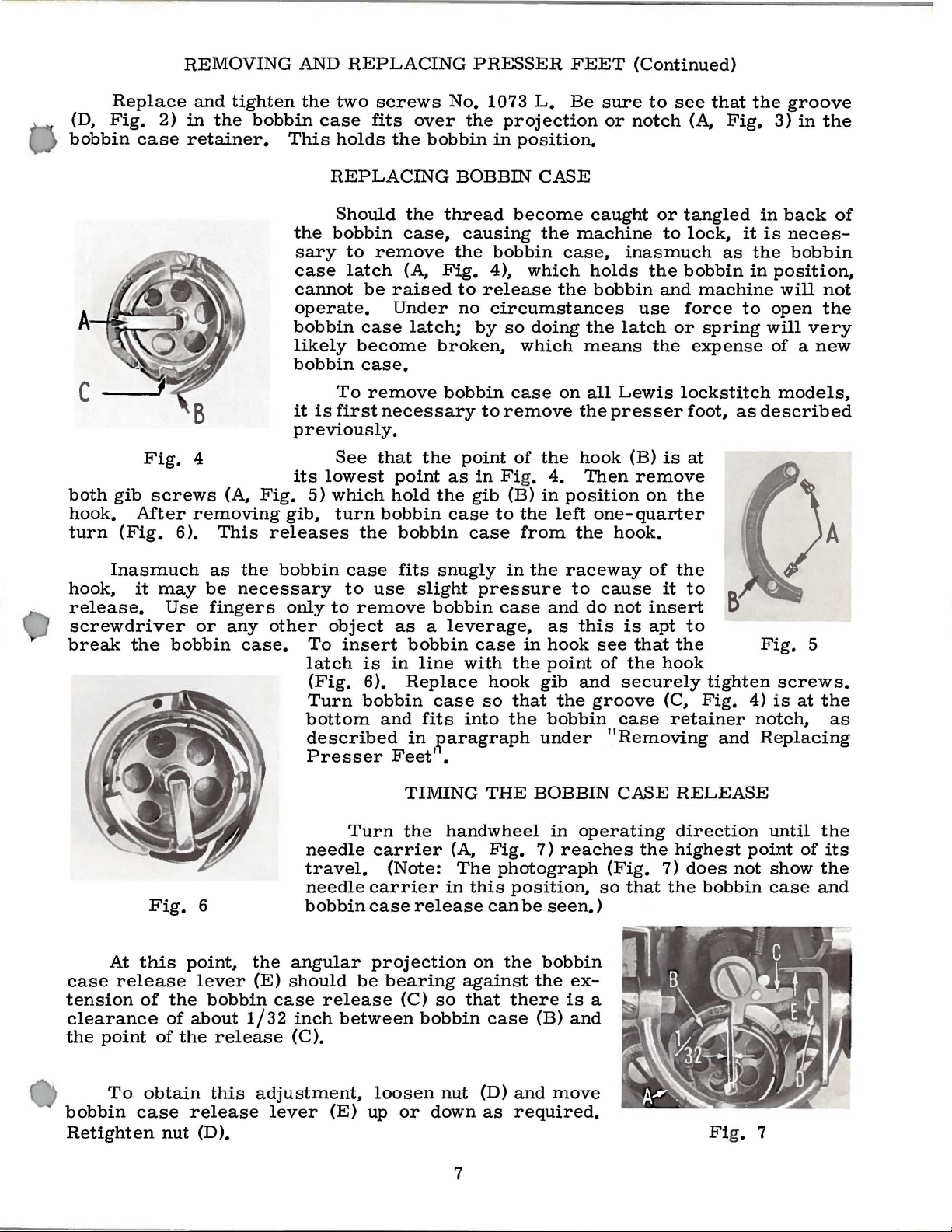
Replace
(D,
Fig.
bobbin
A
C
both
gib
hook.
turn
case
Fig.
screws
After
(Fig.
and
2)
in
retainer.
4
removing
6).
tighten
the
(A,
This
the
bobbin
This
the
sary
case
cannot
operate.
bobbin
likely
bobbin
it
previously.
its
Fig.
gib,
releases
two
screws
case
is
lowest
5)
fits
holds
REPLACING
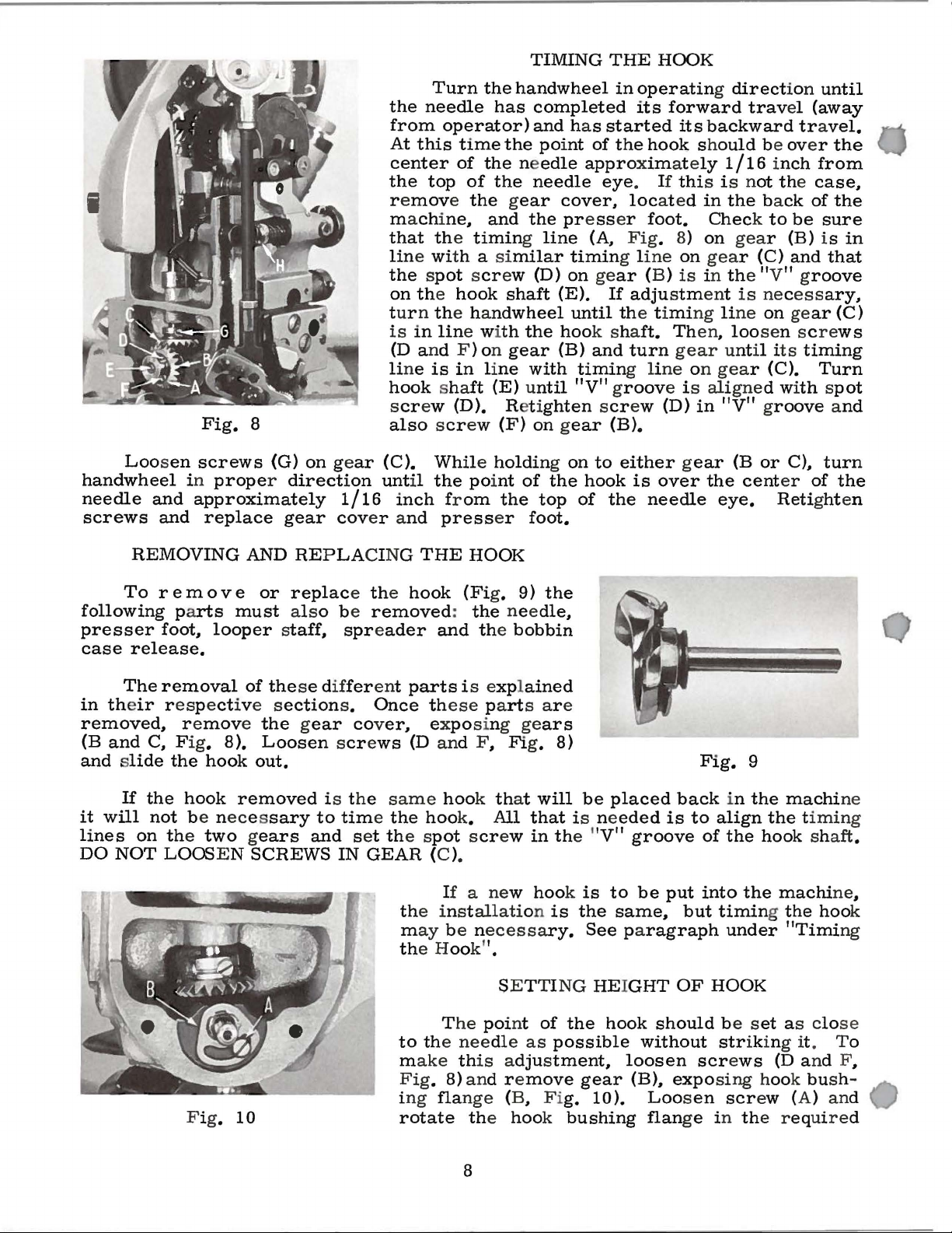
Should
bobbin
to
remove
latch
be
case
become
case.
To
remove
first
necessary
See
that
which
turn
bobbin
the
over
the
bobbin
the
case,
(A,
raised
Under
latch;
the
point
hold
bobbin
No.
1073
the
BOBBIN
thread
causing
the
Fig.
broken,
bobbin
the
4),
to
release
no
circumstances
by
to
point
as
in Fig.
gib
case
case
L.
projection
in
position.
CASE
become
the
bobbin
which
the
so
doing
which
case
remove
(B)
to
of
the
from
on
the
4.
in
left
Be
sure
or
caught
machine
case,
holds
bobbin
the
latch
means
all
Lewis
the
presser
hook
Then
position
one-
the
hook.
to
see
notch
inasmuch
use
(B)
remove
quarter
or
tangled
to
the
bobbin
and
force
or
the
lockstitch
is
on
the
(A,
lock,
expense
foot,
at
that
the
Fig.
it
as
the
in
machine
to
spring
as
groove
3)
in
the
in
back
is
neces-
bobbin
position,
will
not
open
will
of a new
described
the
very
models,
A
of
Inasmuch
hook,
release.
screwdriver
break
case
tension
clearance
the
it
the
At
release
point
Fig.
this
of
may
Use
bobbin
point,
the
of
about
of
the
as
be
fingers
or
any
6
lever
bobbin
release
the
bobbin
necessary
only
other
case.
the
(E)
1/32
To
latch
(Fig.
Turn
bottom
described
Presser
needle
travel.
needle
bobbin
angular
should
case
inch
(C).
case
to
to
remove
object
insert
is
6).
bobbin
Turn
carrier
case
projection
be
release
between
fits
snugly
use
slight
bobbin
as a leverage,
bobbin
in
line
with
Replace
case
and
fits
into
in
~aragraph
Feet'
carrier
(Note:
bearing
•
TIMING
the
handwheel
(A,
The
in
release
(C)
so
bobbin
this
against
that
in
the
pressure
case
case
in
the
hook
so
that
the
THE
on
BOBBIN
Fig.
can
case
7)
photograph
position,
be
the
the
there
(B)
raceway
to
and
do
as
this
hook
point
gib
and
the
bobbin
under
in
operating
reaches
seen.)
bobbin
ex-
is
and
of
cause
not
insert
is
apt
see
that
of
the
securely
groove
case
"Removing
CASE
the
(Fig.
so
that
a
the
it
to
to
the
hook
tighten
(C,
Fig.
retainer
and
RELEASE
direction
highest
7)
does
the
bobbin
Fig.
screws.
4)
is
notch,
Replacing
until
point
not
show
case
at
of
5
the
as
the
its
the
and
To
bobbin
Retighten
obtain
case
nut
this
release
(D).
adjustment,
lever
(E)
loosen
up
or
nut
down
7
(D)
and
as
required.
move
Fi
g. 7
Page 8
TIMING
THE
HOOK
Loosen
handwheel
needle
screws
and
and
Fig.
screws
in
8
(G)
proper direction
approximately
replace
gear
on gear
1/16
cov
Turn
the
needle
from
At
this
center
the
top
r e
move the gear
machine~
that the
line wi
the
operator)
time
of
the needle
of
timing line
th a similar
the spot scr
on the
hook
tur n the ha
is
in
lin
e wi
(D
and F ) on
li
ne
is
in
line
hook
sha
ft
screw (D). Ret i
also scr
(C).
until
ew
While holding on
the poi
inch from
er a
nd
press
handwheel
has
completed
and
the poi
the
needle
and
the presser
ew (D)
shaft
ndwheel
th
the
gear
with
(E) until
ghten scr
(F)
on gear
nt
of
the
top
er
foot.
in
operating direct
its
forward
has
started
nt
of
the
approxim
eye
cover~
loc
its
hook should
at e
ly
.
If
thi
s i s n
ated
in
foot.
(A
Fig
. 8)
1
timing li
on gear
(E).
If
ne
(B) is in the "V" g
adjustment
on
on
until the timing line
hoo
k sha
(B)
and
timing li
"V" groov
ft.
Then~
turn
gear until its
ne
on
e i s ali
ew (D)
in
(B).
to
either gear
the
hook
of
the
is
over
needle
ion
until
trav
el
(away
backward tra
be over
1/16 inch
ot the
the back
Check to
gea
r (B) i s
gea
r (C)
from
case~
of
be
and
roove
is
necess
on gear
loosen screws
timing
gea
r (C).
gne
d wi
Turn
th spot
"V" groove and
(B
or
C)1 turn
the
cent
er
of
eye.
Retight
vel.
the
the
sure
in
that
ary~
(C)
the
en
REMOVING
To r em
following parts
presser
case
in the
removed~
(B
and
and slide
it
will
lines
DO
NOT
foot~
release.
The
removal
ir respect
r e
C~
Fig. 8).
the
If
the
hook
not
be neces
on the
LOOS E N
move the gear
hook
two gears
AND
o v e
must
looper
of
ive s
removed
REPLA
or
replace the hook
also be
CING
removed
staff1 spreader
the
se different
ection
s.
cover,
Loosen screws
out.
is the
sary
SCREWS
to
time the
and
IN
set the s
GEAR
THE
HOOK
(Fi
:
the
g. 9)
nee
and the
parts
i s expl
Once these part
exposing gears
(D and F1 Fi
same
hook th
hoo
k.
pot scr
All
ew
(C ).
If
a new
th
e inst
m
ay
th
e Hook"
be n
allati
ecess
.
SETTI NG
the
dle
bobbin
ained
s ar e
g.
8)
at
will
that
in the "
hook is
on
is
ary.
1
be
placed
is ne
eded
V"
groove
to
be
the
same1 but
See paragraph
HEIGHT
back
is
put
OF
Fig.
to
in
align
of
the
into
9
the
the
timing the
under
HOOK
machi
the timing
hook shaft
machi
ne
hoo
"Timi
ng
ne
.
1
k
T
he
poi
nt
of
Fig.
10
to the
m
Fig
ng
i
rotate
needle
as
possible
ake this adjustment1 loosen
. 8) and r e
fla
nge
move
(B1 Fi
g.
the hook bushing
8
the
gear
hook
should
without
be s
str
screws
(B)1 exposing hook bu
10).
Loosen
flan
scr
ge in the required
et
as close
iking it. To
(D
and F
sh-
ew (A) and
1
Page 9
SETTING
HEIGHT
OF
HOOK
(Continued)
direction
cannot
in
the
Replace
The
(H,
Fig.
set
sufficiently
make
needle
Fig.
more
against
so
very
grades
stitch
and
plunger,
this
The
11
tightly
as
to
little
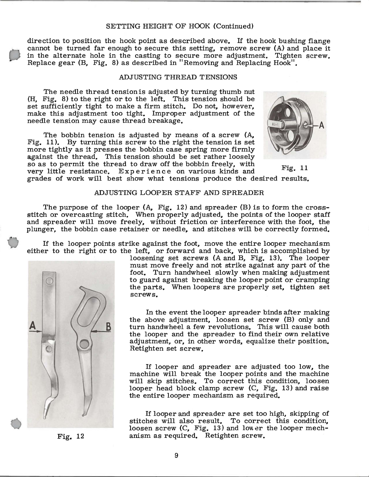
The
or
spreader
to
position
be
turned
alternate
gear
needle
8)
to
adjustment
tension
bobbin
).
By
as
the
thread.
permit
resistance.
of
work
purpose
overcasting
the
bobbin
far
hole
(B,
Fig.
thread
the
right
tight
may
cause
tension
turning
it
presses
the
will
ADJUSTING
of
the
will
move
case
the
hook
enough
in
the
8)
as
ADJUSTING
tension
or
to
to
make a firm
too
tight.
thread
is
this
screw
the
This
thread
Ex
best
looper
stitch.
freely,
retainer
tension
show
point
to
secure
casting
described
is
adjusted
the
left.
Improper
breakage.
adjusted
to
bobbin
should
to
draw
p e r i
en
what
LOOPER
(A,
When
without
or
as
described
this
to
secure
in
"Removing
THREAD
by
This
stitch.
by
means
the
right
case
be
off
the
c e
on
tensions
STAFF
Fig.
properly
12)
friction
needle.
above.
setting,
more
TENSIONS
turning
tension
Do
not,
adjustment
of a screw
the
tension
spring
set
bobbin
various
and
adjusted,
rather
produce
AND
and
more
freely,
spreader
or
stitches
If
the
remove
adjustment.
and
thumb
should
however,
firmly
loosely
kinds
SPREADER
the
interference
screw
Replacing
nut
be
of
the
(A,
is
set
with
and
the
desired
(B)
is
points
will
hook
to
of
with
be
correctly
bushing
(A)
and
Tighten
Hook".
Fig.
results.
form
the
the
looper
the
flange
place
screw.
11
cross-
staff
foot,
formed.
it
the
either
A
If
the
to
Fig.
looper
the
right
12
points
or
to
B
strike
the
left,
loosening
must
foot.
to
guard
the
screws.
the
turn
the
adjustment,
Retighten
machine
will
looper
the
stitches
loosen
anism
against
move
parts.
In
above
handwheel a few
looper
If
skip
entire
If
the
or
forward
set
Turn
against
the
event
adjustment,
set
looper
will
stitches.
head
looper
looper
will
screw
as
required.
foot,
screws
freely
handwheel
When
the
and
the
or,
in
screw.
and
break
block
and
also
(C,
move
and
back,
(A
and
and
not
slowly
breaking
loopers
looper
spreader
other
spreader
the
To
clamp
mechanism
spreader
result.
Fig.
Retighten
are
loosen
revolutions.
words,.
looper
correct
screw
13)
the
entire
which
B,
strike
when
the
looper
properly
spreader
set
to
are
as
are
set
To
correct
and
loVI.
screw.
looper
is
accomplished
Fig.
against
find
equalize
points
this
(C,
required.
13).
making
point
binds
screw
This
their
adjusted
and
condition,
Fig.
too
high,
er
the
any
or
set,
after
(B)
will
own
their
too
the
13)
this
looper
mechanism
by
The
looper
part
of
the
adjustment
cramping
tighten
only
cause
relative
position.
low,
machine
and
skipping
condition,
set
making
and
both
the
loosen
raise
mech-
of
9
Page 10
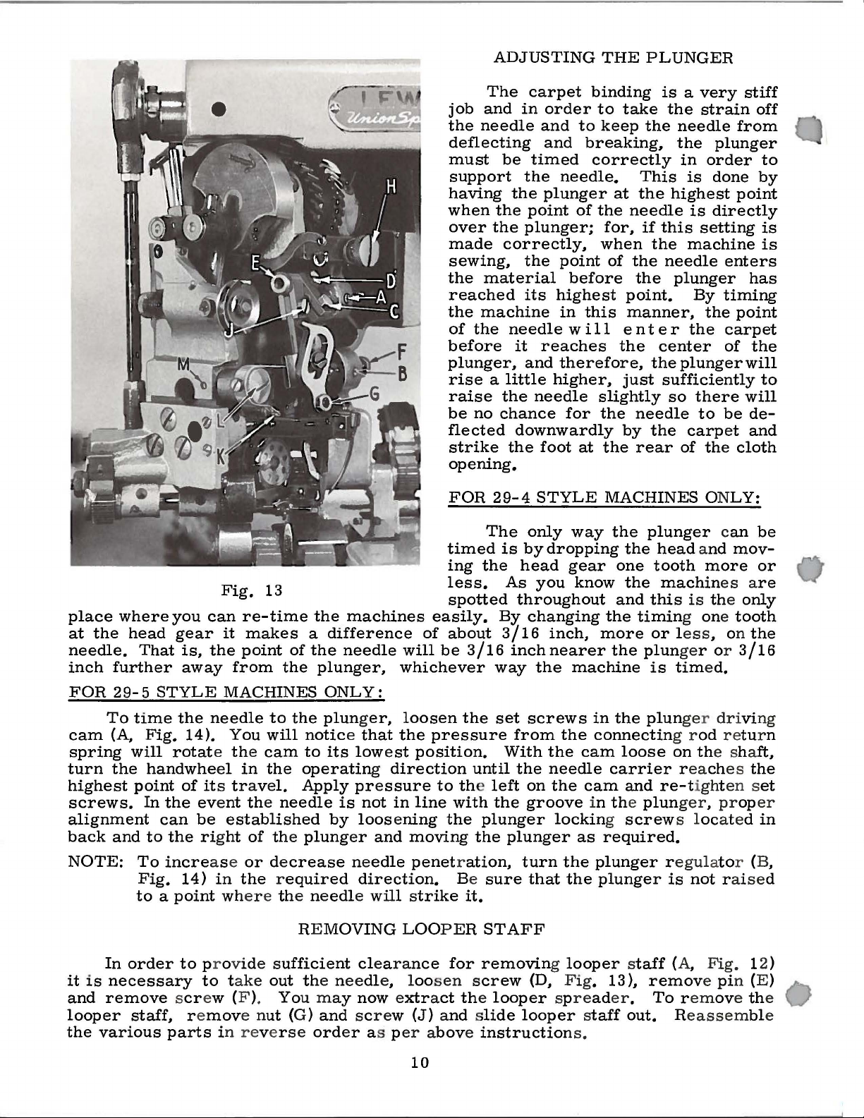
ADJUSTING
The
carpet
job
and
in
the
needle
deflecting
must
support
having
when
over
made
sewing,
the
reached
the
of
before
plunger,
rise a little
raise
be
flected
strike
opening.
be
the
the
the
correctly,
material
machine
the
needle
it
the
no
chance
downwardly
the
timed
the
point
plunger;
the
its
and
order
and
and
needle.
plunger
of
point
before
highest
in
w i 11
reaches
therefore,
higher,
needle
for
foot
THE
binding
to
take
to
keep
breaking,
correctly
at
the
needle
for,
when
of
the
point.
this
at
manner,
en
the
just
slightly
the
by
the
PLUNGER
is a very
the
the
needle
the
in
This
the
if
the
needle
rear
is
highest
is
this
setting
the
machine
needle
plunger
By
t e r
the
center
the
plunger
sufficiently
so
there
to
the
carpet
of
strain
from
plunger
order
done
point
directly
enters
timing
the
point
carpet
of
be
the
cloth
stiff
off
to
by
is
is
has
the
will
to
will
deand
place
at
needle.
inch
FOR 2 9-5 STYLE
cam
spring
turn
highest
screws.
alignment
back
NOTE:
the
further
To
(A,
the
and
where
head
you
gear
That
time
will
point
To
Fig.
to a point wher e the ne
is,
away
the
Fig.
14).
rotate the cam
handwhe
of its trave
In
the eve
can
be
to
the rig
incre
14)
Fig.
can
the
needle
el
ase
in
13
re-time
it
makes
point
from
MACHINES
to
You
will notice that
in
the
l.
nt the
established
ht
needle
of the
or decrease
the required
the
machines
a
difference
of
the
needle
the
plunger,
ONLY:
the
plunger,
to
its
lowest
operating direction
Apply pre
is
by
loosening
plung
er
ne
direction.
edl
e will s
not
and
edle
ssure
in
will
whichever
loosen
the
moving
penetration,
FOR
timed
ing
less.
spotted
easily.
of
about
be
3/16
the
pressure
position.
until
to the left
line
with
the
Be
trike
it.
29-4
The
is
the
As
throughout
By
3/16
inch
way
set
from
With
the
the
plunger
the
plunger
sure
STYLE
only
by
head
changing
screws
on
groove
turn
that
way
dropping
gear
you
know
inch,
nearer
the
machine
the
the
cam
needle
the
cam
in the
locking screw
as
the
the
MACHINES ONLY:
the
plunger can
the
head and
one
tooth
the
machin
and
this
the
timing one tooth
more
in
connectin
carrier reaches
required.
plunger regulato
plunger
or less
the
plunger or
is
the
plunger driving
loose
and
re-tigh
plun
more
es are
is the
, on
tim
ed.
g r
od
r etur n
on the sha
t en s
ger, proper
s located
is
not
r aised
be
mov-
or
only
the
3/16
ft,
the
et
in
r (B,
RE
In
it
is
necessary
and
remove scr
looper
the
various
order
staff,
to
r e
parts
pr ovide s
to take
ew (F ).
mov
e n
ut
in rever
MOVING
ufficient clearance
out the needl
You may now extract the
(G)
and screw (J) and slide
se
ord
er a s p
LOOPER
e, loos
er above instruction
10
STAFF
for
removing looper staff
en screw
looper
(D, F ig. 13
spreader.
looper staff
s.
(A,
Fig.
),
remove pi
To remove the
out. Reassemble
12)
n (E)
Page 11

THREAD
BREAKAGE:
HOW
TO
OVERCOME
Mter
inclined
needle
When
this
needle
cost.
However,
veniently
emery
Other
wear
where
corners
When
parts
have
parts;
No.
er
No.
through
become
needle
430-37,
No.
12-16
considerable
to
cut a sharp
guide
{A,
occurs,
guide,
procurable,
cloth
to
parts
the
that
create
thread
which
looper
37-4,
thread
and
Fig.
which
if a new
eliminate
of
the
thread
breakage
sharp.
guide,
staff
the
needle.
service,
edge
15
),
we
recommend
can
smooth
sharpness.
machine
passes
thread
the
thread
We
needle
No.
take-up,
in
causing
be
done
needle
the
will
over,
breakage.
occurs,
passes
refer
clamp
36-14,
bobbin
Th
too tight
conditio
it
has
Old
bobb
the
needle
the
groove
thread
will
of
breakage.
replacing
at a very
guide
is
groove
small
not
with
eventually
causin
check
to
and
looper
to
the
thread
case :ret
g sha
up
see
follow
spread-
on the
if
gui de
ainer
read breakage
in the
n, at the
a t enden
ins s
bobbi
cy
hould
sam
to warp and bind
be
the
the
con-
an
show
rp
they
ing
may be
n ca
e ti
be di
se.
me
scarde
Fig.
caused by the
While this
a s the
is not
bobbi
in
the bobbin case
d.
14
bobb
in being
a fr
eque
nt
n becomes old,
.
Fig
. 15
nsions"
Te
If
hr
ead breaka
t
In
are no sharp
. Also exami
the
bobb
in
ge
spe
ct the loop
poi
ne t
is woun
d t
will result.
er
st a
ff and looper sp
nts
to
cau
operation, thread breakage
which
tight. Ch
mu
Thre
st
be thor oug
ad br
eck
eak
up
age
on th
hly rem oved
may also occur
is.
MISSING OR SKIPPING STI
Wh
en
the
machine co
ve
rcome th
o
ing should appear when t
is difficu
lty. The
he
Thread breaka
g.
{F i
9) is impr op
hook to fail
pr op
er
tim
instructio
Al
are
he
oo
full,
s e thr
m ay be d
ns
ways see that t
cor
r ect.
nee
d 1 e guide a
or if the thread ha s
ead
ue
as per instru
mmences to
m ac
sketch
hine
imm
is
ge
may als
erly time
to pic
e.
on "Tim
k up
Wh
en this occu
ing
the
the Hook".
he needle
See instruction
nd
reader from tim e
br eakage.
On
to accumulatio
cti
ons
if
the needle t ens
TCHES
skip
stit che
edi ate
ly
s,
bel
oper ating pr operl
o be caused
d,
caus
ing the point of
loop
fro
r s,
re-time the
and
bob
m the
bin threa
s on "Adjusting
presser
foot
for
become tangle
to
time
to
a new
n of o
on "Sett
it
ow shows how
ion
machi
il
is
ne just
in the hook {
ing
Up~'.
set
is a very simple matt
the bli
y.
if
nee
hook as
shar
d in the
see
too
loo
t
he hook
the
dl e at
the
per
d t
ensions
Thread
p edges.
bobbin,
that there
put into
Fig
. 9
se
or
too
er
to
nd
stitch-
),
11
Page 12

If
needle,
the
plain
loopers
stitching
MISSING
are
skipping,
machine,
OR
SKIPPING
the
stitch
as
follows:
STITCHES
will
appear
(Continued)
like
work
produced
on a two-
When
stitch
out
this
foot,
the
will
If
it
of
time,
trouble
so
needle
If
machine
controller
spreader
to
the
right
controller
screw
If
(M,
the
plunger,
the
appear
is
that
to
spring
are
spring
Fig.
hook
the
looper
found
follow
can
be
they
pass
skips
at
their
which
13)
is
stitches
occasionally
like
this:
that
the
skippinR
instructions
overcome
will
over
carry
the
stitches,
(K,
Fig.
lowest
holds
become
and
the
thread
removing
cause
will
appear
worn
on
by
the
thread.
13)
to
point.
out
of
skipping
picks
is
caused
Adjusting
slightly
thread
see
that
carry
This
controller
it
may
the
stud
stitches,
as
follows:
up
the
thread
by
the
Looper
lowering the
down
all
spring
sufficiently
there
the
is
slack
may
spring
be
replaced
and
thread
or
or
and then
looper
Staff
and
point
far
sufficient
thread
be
tightened
in
position.
by
controller
if
needle
miss
staff
and
Spreader".
of
the
to permit
tension
when
by
Should
loosening
spring.
is
out
es
the
spreader
loopers
the
on
the
the
looper
turning
the
the
of
time
loop,
the
being
Generally
into
the
point
thread
and
stud
(L)
thread
small
with
set
the
of
The
hook
carry
this,
the
work
is
the
it
Hook".
properly,
Bent
that
the
See
illustration
Proper
tance.
if
reasonable
machine
parts,
by
the
red
In
cleaning
the
parts
see
the
drops
of
necessary
long
runs
not
picking
thread
is
necessary
The
or
or
blunt
needle
showing
lubrication
Lewis
Invisible
care
should
causing
be
them
paint.
the
with a clean
various
oil
should
to
place a drop
of
thread
up
back
to
sketch
that
needles
is
sharp;
is
oiled
machine,
moving
be
the
through
re-time
to
it
is
also
needle
and
Stitch
taken
and
to
function
cloth.
parts,
placed
of
between
thread
the
the
the
right
out
of
are
frequently
that
guide
OILING
thorough
Machines
in
cleaned
always
Do
bearings,
on
oil
each
from
goods
hook
time
is
the
(A,
the
without
with
an
with
point
Fig.
AND
cleaning
will
keeping
them
daily
improperly.
remove
not
use
waste.
these
in
back
small
of
stitch
on
needle,
completing
the
needle.
indication
the
plunger.
the
cause
of
needle
15).
CLEANING
of
machine
give
years
properly
as
lint
and
The
the
cover
By
gears,
feed
parts
the
bobbin
sketch
thereby
that
of
stitch
dirt
places
from
turning
dogs
daily.
case
to
the
causing
the
stitch.
See
paragraph
the
needle
skipping.
bears
of
is
of
service
oiled
on
and
accumulate
to
be
oiled
the
the
handwheel
and
On a new
raceway
left
shows
the
To
on
is
not
Always
the
needle
paramount
and
satisfaction
cleaned.
in
the
are
head
oil
and
holes.
machine,
every
that
the
needle
to
overcome
"Timing
doing
its
see
guide.
impor-
The
moving
indicated
wipe
you
A
it
two
off
will
few
is
or
12
Page 13

OILING
AND
CLEANING
(Continued)
three
well
the
the
base,
plate
Accumulation
hours.
placed
Besides
plunger
machine
On
all
immediately
It
is
also
near
See
the
that
You
will
will
do
more
thoroughly
and
feed
immediately
types
of
below
necessary
handwheel.
the
feed
of
lint
find a hole
good
oiling
mechanism.
below
machines
the
to
oil
wheels
in
feed
immediately
than
ten
drops
the
head
The
the
presser
there
handwheel.
the
wheels
are
are
head
cleaned
will
to
that
mechanism
feed
of
mechanism
foot.
movable
the
machine
every
cause
the
do
not
it
parts
day
the
left
of
reach
is
also
will
that
at
the
to
machine
the
hook.
the
necessary
be
require
top
avoid
to
parts
found
by
turning
lint
feed
A
drop
requiring
to
in
oiling
accumulating.
improperly.
of
lubricate
the
bed
near
back
oil
it.
of
the
the
13
Page 14

LEWIS
CARPET
BINDING
MACHINE
Binding a carpet
an
overhead
single
which
track.
is
rolled
It
LEWIS
and
is
of
simple
CARPET
held
in the
construction
BINDI
trough
NG
MACHINE
of a conveyor
and
does
not
suspend
take
much
ed fr
space.
om
R
oll
er
Co
nve
blind
yor used by
stitching the
edge of the
som
e manufactur
bind
ing
to the
er s
bac
for
k of the
14
hold
ing the r
carpet.
oll
ed carpet
when
Page 15

LEWIS
CARPET
BINDING
MACHINE
Carria
Carpet
ge
conveyor
Binding
with
Machine.
track
LEWIS
on
floor showing
CARPET
operator
BINDING MACHINE
binding a rug
on a LEWIS
Showing
binding,
LEWIS
with
the
Carpet
carpet
Binding
laying
Mach
on a car
ine
in
position
riage type conveyor.
15
to start blin
d a
titrhing
the
Page 16

57-19---
99-219-
1220L
1221L
-~
-
---
125
~
-
-4124-40
-147-10
23
155-12
433-123
Complete
......
en
~~:~~
14-327
18-412
1750L~
45-231
14-
305
46
-to 2
13
7-19
15
_,
175
45-233--
44
7-9 6 Complete
4124-39
18-355
50-144---~
35-13
22-177
166-3---~
18-705
49-21
49-20·
40-46
LS
214
79-24
1298L
18-121
======
---
--
--
2
--
OL
--
--
-_ _ ___
-
~==
--
- -
--
---f
---
Complete
- -
--....
---
==~~~~~~~~~!§~!!~~
~
=tt===~~~~
-
'r-+--
-\-\-1-+--~
--l,,../---f-+--11-"'"
--+--+---+
-----,1~
.......
~4-292
99-216
165-6
18-706
-
--
----J
4149-18
2-~2
18-132
115-86 FP528
18
t8-686003L
~~21
22-177
;;;1003L
1
115-81
79-24
165-~
140-9
3-48CSASf)
18-50
~8R6,.,~9
18-705
24-39C
41
18-680
21-70
115-86
FP528
50-140
166-3
-705
-70
18-683
39-82
LS214
40-46
1071L
99-221
18-914
I003L
18-688
0
omplete
50-145
18-270
18-132
35-14
"'--
--
--
~
-I022L
-99-211
75-147
-18-720
~35-7
~18-178
l8-
~~=f~~(S££
-·
14-308
690
'-122
1221L
50-139
-4-83
475-147
LIST)
21-70
75-147
14-302
Guide
Complete
114-96-1
475-147
Guide
Complete
50-139
14-302
888L
1058L
117-34
3:S-7
"'G
r-
,.
-1
..,
....
Page 17

......
-J
18-1044
1200
125-2~
1005
16-.311
18-689
137-20
1197-=--...
18-680
21-70
Spring
166-2
18-683
~
57-18
.,
r-
~
I'll
N
114-96-
2
Page 18

1-'
00
14-327
433-123
18-689
147-10
155-12
18-250
IS-
679
1s-soo
4149-18
18-67
3
I \
~~
~---------1225L
_../1
..............-
c rs:a&Jr fT'"'n..
I....Yai
:/:/
32-159
20-91
s-268
1
5
(8AS
f:
~~:!~
18-412
131-12
1005L
4124-42
33-128
3-48
433-127
18-730
.,
r-
;a:.
-4
Ill
w
J
=--------4!5-241
115-85
4-310
FP341
11-4-96-3
Page 19

......
co
I
4•83]
~~~~~e~~
26-91
110-188
18-713
1003L
14-306
35-14
18-706~
(Nutii
60L)
FRO
N T
18-914
45-238
1005L
18-690
433-127
16-250
1333L
57-18
45-221
18-1045
22-175
447-91
16-239
45-241
FP341
18-1045
14-310
s
81~
439-7
16-252
.,
r-
,.
~
..,
~
99-21
114-96•4
Page 20

IOOIL
1005L
1002L
1006SL
1004L
1019L
1021L
1022L
125-23
1181L
1420L
4ltO
t-.:)
0
100
1187L
IOIOL
1059L:
1009L
118-23
75-145
1351L
405-34
~
"'-=
~
~
'----------+---1
'---------1!---
LS330
1080L
28-2
18-1045
1071L
14-307
430-37
Needle
Clamp
. . l 1152L
16-269
~
18-1059
-
:::::
39
-IS
5
:::...._117-4-~
T
- 16-.,s'6 1170L
7
~T
~
·~
.........._
IIBOL
1060
1053L
445-242
Release
411-5
6-37Needle
5
L
Bobbin
Complete
Bobbin
Comple,e
__l
-1137L
I
1
Case
Case
Guide
18-715
1005L
1166L
IOIIL
1054L
1012L
Complete
,
E
"'
Ul
114-96-5
Page 21

1058L
1:\:)
......
16-264
32-150
1031L
1026L'
1750L
14-305-
45-231
1024
1031L
Bushing
15-12
45-233
68-16
21-184
113
155
·-
1055L~·
1351L
75-145
1058L
405-346
018AL
22-195
1557L
1556L
1183L
~--1558SL
CS231
1188L
1189L 1185L
l\:t:~:E=:::=:~II~8~7L
/
...__t081L
...__1056L
~ua-23
t029L
_
19
68
118
6l
1055L
tS-719
430-37
Complete
13-22
409-25
1034AL
Complete
43
7-4
Complete
"'0
r-
)111
-1
I'll
en
1029L
..
_ - "
405-3
411-5 Bobbin Case Complete
46
Foot ete
3-48(BA5£')
114-96-6
Page 22

447-134
PLATE 7
~
I
I
75-250
_-.J/\
J1.
1
~
7
34
- 97
MAll\~
S~~FT
1009
71-59 -····
L
:r
i2)
I
L:
__
18
26-188
4124-42
- 91
22
Page 23

on
The
Style
following
29-4.
See
parts
picture
list
indicates
plate
No. 7 on
PARTS
the
LIST
parts
used
opposite
on
page.
Style
29-5
that
are
not
used
Part
No.
18-576
21-218
23-336
26-188
34-97
22894
69-23
447-134
20-80
20-81
22-325
35-34
71-59
75-250
121-7
4124-42
18-391
12934
22874
22874
*
4129-10
14-287
18-493
22-175
45-222
18-690
1005
70-28
71-87
1388
1025
4129-18
22508
11698
43139
51170
X
A
E
F
L
L
L
L
A
D
Description
Screw1 for
Spring~
Feed
Wheel~
Plunger
Plunger
Set
Slide
Block
Plunger
Nut~
Nut~
Dowel
Cam
Connecting
Guide
spring
for
connecting
front
No.
21-218"----------------
rod
and
rear----------------------
-----------------------------------------Cam--------------------------------------
Screw-------------------------------------------
-------------------------------------
Connecting
right
left
hand
Rod
Assembly-----------------
hand
thread-------------------------
thread---------------------------------
Pin------------------------------
Follower
Roller
Rod-----------------------
Fork
--------------------------------
Frame----------------------------------Ball
Joint---------------
Screw---------------------------------
Nut
--------------------------------------------
Screw------------------Screw----------
Knee
Press~
Shaft1 for
Screw~
Pin1 for
Knee
complete~
No.
for
No.
No.
Pre
ss
Screw----
Lever---------
-
------------------for
45-222----------
70-28---------
45-222
-
-------------------------------------
Screw--------------
Sleeve~
Knee
Collar~
for
Press
for
connecting
Rod-------
No.
14-287-----------------------
Screw---------------
Knee
Press
Pad~
complete-
Screw------------
Nut~
Nut1 for
Nut~
for
screw
connect
for screw
No.
ing r
No.
18-576
od
No.
18-576
No.
447-134--------------
--------------------------
-
-
--------------
-
-----------------
-
-------
droppi
-------
kne
-
--
---------------
ng
lower roller-
-
---------
-
------------
-
---------------
---e p
---
-----
-----
- - -
--
----
------- --
ress
to
------
----------
- -
----------
- - - -
base-----
----------------------
-
--------------
-
----
---------------
447-134-----------------------
---------
-
---------------------
-
-----------
-
-
-------
-
- - ---- 1
-
-------
--
------
---
--
---------
- - -
----
-- -------
--
- - - - -
-
--------
--
-------
- - -
------
- ------- - 2
--
------
- - - - -
---- - - -
-
-------
- -
---
----------
--
------
- - -
-------
-
-------
- ------------
---- - -
------
- - -
- 1
-----
- 2
---
- - 1
---
- 1
---
- 1
--
- 1
- - - - 1
-
---
-----
-----
- - 4
-----
- - - 1
- 1
- 1
- 1
---
Amt.
Req.
1
2
1
1
1
1
1
1
2
4
1
1
1
1
2
1
1
1
1
1
1
2
Compo
indicated
nen
by
t parts
indenti
ng
of
s
ub-assemblies~
their
descriptions
which
can
under the des c
assembly.
*Not
shown
Styles
29 - 4
on
or
pictu
29-
re
5.
plate
No.
7.
Available
as
extra send
23
be
furnished
ription
and
for
repairs~
of the
charge
are
main sub-
item~
for
Page 24

PARTS
LIST
Part
No.
4-83
6-37
8-97
12-16
13-22
14-271
14-287
14-292
14-302
14-305
14-306
14-307
14-308
14-310
14-327
15-12
16-239
16-250
16-251
16-252
16-264
16-269
16-365
16-381
17-104
17-110
17-171
18-40
18-121
18-132
18-178
18-250
18-268
18-270
18-355
18-391
18-412
18-500
18-547
18-576
18-633
18-634
18-670
18-672
Description
VVork
Needle
Guard#
Retainer#
Gib,
Shaft,
Shaft#
Shaft,
Shaft#
Shaft#
Shaft#
Shaft#
Shaft#
Shaft#
~ain
Crankshaft#
Bushing#
Bushing,
Bushing#
Bushing,
Bushing#
Bushing#
Bushing#
Bushing#
Eccentric
Stud#
Looper
Screw,
Screw#
Screw#
Bearing
Support
Guide#
for
for
hook
for
for
for
for
in
for
for
for
for
Plate--------------------------------------
on
front
for
bobbin
No.
front
knee
rear
carpet
arm
for
rear
looper
front
plunger
presser
feed
409-25
feed
lift
feed
edge
thread
feed
pinion
feed
cradle
roll
No.
roll
roll
roll
foot
No.
wheel------------------------------
case#
on
presser
--------------------------------
holder
No.
4129-10---------------------------
holder
guide
tension
No.
No.
No.
No.
No.
No.
75-147
release
35-14------------------------
1152 L -----------------------
35-14
140-9-----------------------
Shaft----------------------------------------------
in
and
No.
in
in
left,
right#
cradle
for
for
1152
for
for
for
lower
Crank
for
for
for
Screw#
head#
base,
base#
for
for
shaft
tension
shaft
L--------------------------------------------
adjusting
main
Stud#
for
end
Stud--------------------------------------
flange
end
of
spring
for
for
tension
for
knee
for
knee
shaft
feed
No.
14-310-----------------------------
press#
press#
No.
roll
release
No.
14-307#
looper
shaft#
head
vertical
of
regulator
No.
107-39-----------------------------
shaft
No.
roll
No.
21-237
No.
release-------------------
14-271#
holder
crankshaft
for
spreader
end------------------------
adjustment
link
14-292,
----------------------------
35-7#
405-346
foot
99-221----------------
99-216
-----------------------
rear-------------------front
for
shaft
looper
No.
for
for
stretching
binding-----------------------------------------------Screw#
Screw#
slide
Stop
roll
Screw.
ridge
Screw#
4124-42
Screw#
Set
No.
Screw#
Screw#
Spot
Set
Adjusting
Screw#
No.
for
for
block
Screw#
No.
for
in
for
in
Screw#
17-110,
for
f.or
Screw#
Screw#
for
20-95#
plunger
eccentric
in
for
37-7
holding
carpet
ball
1/2
-------------------------------------------
arm
for
for
No.
spring
for
for
Screw#
key
in
adjusting
base
-------------------------------------
pivot
in
No.
roll
on
Style
casing
for
spring
plunger
lower
No.
block
475-147----------------------------
No.
cap
regulator
end
regulator
433-127#
No.
35-13,
29-4
----------------------------
on
Nos.
hook
for
115-86#
for
4124-39
No.
131-12
No.
of
regulator
45-221-----------------------------------
No.
feed
feed
for
No.
21-218#
wheels
wheels
plunger
108-6#
on
Nos.
Nos.
regulator
for
plunger
Style
23-205,
23-205#
arm-------------------------------------
indicator
locating
ironing
4149-18
adjusting
----------------
No.
405-346
----------------
------------------No.
45-231
-------------------
feed
roll
holder
No.
14-271
No.
15-12----------
pinion
No.
437-4
of
loopers----------
gear
----------
46-106------------
rear
feed
roll
carpet
No.
plunger
for
adjusting
plunger
1/2#
----------------and
stud
link
No.
46-106
29-5---------------
23-336-----------
23-336------------
No.
4149-18
--------
nut
-----
--------
----
------
155-12-
----
Plate
No.
1#
5, 6
2
6
6
1,
2
1, 4
1
1,
6
1,
4
5
1#
1,
3#
1,
2#
1, 6
4
2,
3#
4
4
6
5
5
2
6
4
5
1
1#
4
1
1
1, 3
3, 4
1
1, 2
2
1, 3
1,
3#
4
7
2
2
3
1#
3
2#
3#
2#
2#
4
4
3,
4
4
3
4
4
24
Page 25

PARTS
LIST
Part
No.
18-673
18-679
18-680
18-683
18-688
18-689
18-690
18-698
18-705
18-706
18-713
18-714
18-715
18-719
18-720
18-730
18-748
18-787
18-914
18-1044
18-104
18-1056
18-1059
18-1060
20-60
20-80
20-81
20- 91
20 - 95
21- 70
21-75
21-184
21 -
218
5
Screw,
Spot
Screw,
(3)
Bearing
Screw,
front
Spot
Spot
99 - 221
also
Ne
edle
Screw,
feed
Screw
adjusting
Screw,
26-188-------------------------
Screw,
Screw,
Bearing
Adjusting
roll
Set
No.
Screw,
Screw,
Screw,
Spot
Screw,
Screw,
Screw,
Clamp
Knurled
sleeve
Nut,
No.
Nut,
447-96
Nut,
447-96
Nut,
Nu
t,
Spring, for
N
o.
and
Sprin
Spr
Sprin
connecting
for
flange,
Screw,
No.
end,
Screw,
Screw,
for
Carrier
ratchets
Eccentric,
No.
Screw,
45-241-------------------------------
Screw,
for
for
for hol
Screw,
for
32-150
r ig
left
for
for
99-211
No.
g,
ing,
g,
for
for
holding
50-145
Screw,
for
plunger
No.
for
(2)
and
feed
No.
45-221
for
clamping
rear
for
clamping
for
ball
for
clamping
Screw,
Screw,
35-7
for
for
end
for
No.
for
work
for
holding
holding
ding
Looper
No.
70-70-------------
staff
ht
and
hand,
and
adjusting
plunger
for
for
for
No.
on
hand,
447-134---------------------
447-134--------------
plunger
in
166-3
attaching
tension
feed
rod
for
plunger
brackets
on
head------------------------------
for
short
regulating
46-110
No.
433-123
for
front
roll
Driving
------------------------in
feed
feed
casing
in
eccentric
of
21-256,
for
head------------------
for
carpet
-------------------
No.
roll
for
bobbin
knurled,
No.
main
support
No.
1200 L ------head
arm
arm
looper
Spreader
68-18,
for
connecting
connecting rods
feed
adjusting
regulator
release
pressure
447-134
Description
regulator
regulator
ratchet
-------
feed roll
pressure
------------------Stud-----------------
yokes
plunger
No.
475-147--------------
guide
rug
Nos.
roll
No.
cap
No.
448-177---------
case
for
No.
shaft
on
Style
No.
to
arm
to
base
to
base
crank
Adjusting
for
pressure
screw
guide
lever
in
No.
No.
(2)
No.
pawl
link,
-
--------------------------
---
- - - - depressing
spring
49-20
link
No.
35-14
Nos.
433-127,
No. 14-
4-83 -----
thread
pin
No.
arm
on
26-115,
4124-40
release
adjusting
29-4 ---------------------
-
(2
used)--
(2
used)-------
(2
used)-------
stud
Screw,
--
--------
rods
Nos.
-----------
spring
No.
No.
475-147,
No.
475-147
No. 45and for
Sty
le 29- 5 - - - ---------
107-39
4149-18------
50-144
No.
upper end,
--------------------lever
and
46-110,
-------
---- - - 1/2-
for
327
----
No.
clamp
Nos.
No.
18-670
22-79
- - - - -------
----
---------
and
166-2-----------
No.
lever
No.
45-238;
--
---------------
-
----------
49-21,
----
----------for
- --------------26-91
---------------
--
-------------
- -------
lever
tension
---
--------
17-171-
-
447-91,
233
plun
No.
of
--
- - - -
plunger
-
-------
------
-
- - -
--------
- ---- - ---- -
-
-----------
--
---
goes inside
----- - -----
in gear
-----------------447-91,
-
-----------447-92,
-
-------
21-
218
in
arm-------
and
for
for
No.
- -
to
machine--
in
head--------
ger
-
------
--
46-106,
No.
for
and
- - -
-----
445-242
binding
--------
fork
-
----
----
------
----------
---
----
------
- -
--------
--- ---
-----
cover
447-92,
- - - -
- -
------
166-2
-------
----
--
--
- - -
- -
--
--
--
- -
- -
-
-
-
-
Plate
No.
1,
3
1,
3
1, 2
1,
2
1
1
..
4
3
5
6
1
3,
4
2
1, 2
1,
2.,
4
2
2, 5
2, 4
4
5
*
6
2, 7
1,
3
3
1,
2,
3
1,
4
6
2, 3, 4,
7
25
Page 26

PARTS
LIST
Part
No.
21-237
21-256
22-79
22-148
22-175
22-177
22-182
22-195
22-325
23-205
23-336
26-91
26-115
26-188
28-2
32-150
32-151
32-152
32-159
33-128
34-97
35-7
35-13
35-14
35-34
36-14
37-4
39-81
39-82
39-92
39-135
40-46
41-28
43-20
45-221
45-222
45-231
45-232
45-233
45-238
45-241
46-102
46-106
Spring.
in
assembly
Spring
26-115,
Spring
Dowel
Pin,
Pin,
Pin,
Pin,
Dowel
Feed
Feed
Plunger,
Plunger,
Plunger,
Sector
Cover,
Cover,
Cover,
Cover
Eccentric
Plunger
Roll,
Roll,
Feed
Cam
Looper,
Looper
Collar,
Spacing
Thrust
Looper
Washer,
Needle
Rivet,
Lever,
Lever,
Lever,
Lever,
Lever,
Lever,
Lever,
Wire
Link,
for
also
(2)
for
for
Wheel,
Wheel,
screws
21-256,
brush
for
for
Roll,
Follower
and
49-21
49-20
lift
No.
Link,
No.
45-231
for
used
Plate,
Description
for
applying
No.
Brush,
for
Pin,
Pin,
feed
for
binding
thread
Pin,
Nos.
for
for
for
No.
for
Gear,
for
for
for
Cam,
stretching
ironing
for
Spreader,
for
Collar,
Collar,
Staff
for
and
Clamp
(2)
in
in
4129-10----------------------------------------
front,
back,
for
for
forked,
plunger
for
Style
for
(2)
for
roll
in
No.
feed
tension
in
No.
front
front
18-633
carpet
Style
presenting
21-256,
Style
for
hook
head
plunger
for
Sleeve,
for
front
Roller,
looper
plunger
--------------------------------------------for
Bearing
ball
49-21----------------------------------------
Thread
for
holder
base,
base,
for
for
tension
feed
pressure
for
front,
to
lever
pressure
475-147--------------------------------
brushing
29-4----------------------------------
plunger
arm
depressing
45-222
ratchet
roll
and
and
29-4----------------------------------
29-5----------------------------------
looper
gears
----------arm,
for
Style
plunger
and
for
in
yoke,
main
screw
for
on
tension
tension
release,
plunger
for
regulator
regulator
and
pawl
opening
discs
447-134
rear,
rear,
and
when
carpet
for
Style
spreader,
on
opening
for
plunger
29-5
carpet
rear,
in
No.
spreader,
looper
cradle
for
shaft
Collar------------------------------
No.
Guide
No.
99-219,
depressing
knee
lift
release
tension
No.
to
binding
pile
on
top
of
No.
4149-18
base--------------------------
lever
when
No.
crank
No.
-----------------------------for
for
18-634
not
using
29-4
head----------------------------
-----------------------------
in
base------------------------
holding
cradle
-----------------------------
binding
ridge
in
base------------------------
447-134---------------------
complete,
spreader,
No.
feed
No.
79-24
Plate,
shaft
release
on
spring
adjusting
release
45-233------------
in
arm------------------------
No.
knee
head-----------------------
lift
166-3-------------------
No.
1183 L
Style
Style
to
in
140-9
ratchets
feed
in
No.
29-4
29-5;
------------------------spring
needle
-----------------------complete,
thread
No.
on
No.
carpet,
in
14-327,
in
feed
lower,
for
thread
rolls------------------
No.
14-287,
in
arm,
arm,
21-218
eccentric
joining
roll
No.
35-7
plunger
45-221
is
used------------
48-106
------------------
----------------
brush
when
oiling
140-9
475-147----------
for
No.
complete
base---------------
Nos.
handwheel
yokes
in
oil
handwheel
handwheel
---------------
No.
------------in
base;
in
base------
includes
No.
using
No.
Style
437-4---------
No.
for
-------
lever
-
-------------
spring
437-4-----
pads--------
------------
29-4-----
No.
49-20
Nos.
430-37----
pads--------
knee
end----
end----
437-4--
end
---
-
-----
Plate
No.
1
*
3
4
4
1
1, 4
5, 6
7
1
1, 7
1, 4
*
1,
2
6
5, 6
2
1,
2, 3
3, 4
7
1
1, 2
1,
2, 4
7
6
6
4
1
2
5
1,
2
5
2
4
*
1, 6
2
1, 6
3, 4
3, 4
1,
6
3, 4
7
26
Page 27

PARTS
LIST
\
Part
No.
46-107
46-110
48-106
49-20
49-21
50-131
50-139
50-140
50-144
50-145
57-18
68-16
68-18
68-19
69-23
70-70
71-59
71-60
71-61
75-145
75-147
75-250
79-24
79-26
99-211
99-216
99-219
99-221
107-39
108-6
110-188
115-81
115-85
115-86
117-34
117-49
118-23
121-7
125-23
131-12
131-20
137-19
137-20
140-9
144-22
Description
Link,
Link,
in
Crank,
Yoke,
Yoke,
Bracket,
Bracket,
Bracket,
Bracket,
Bracket,
for
for
attaching
feed
roll
carpet gui
holders
de
No.
No.
475-147
99-216
and
base------------------------------------------------
in
with
with
for
for
for
for
for
base,
wide
narrow
for
slots
tension
guide
holder
feed,
feed,
opening
for
slots
release
No.
75-147
No.
rear,
front,
binding
feed
ratchets
for
feed
shaft
in
99-211
on
head------------------
on
head-------------------------
roll-------------------
in
ratchets
No.
14-305
No.
475-147
in
No.
475-147
Handwheel---------------------------------------------Tension
Tension
32-150
Thread
Slide
Sleeve,
Connecting
No.
Connecting
Connecting
Edge
Edge
Guide
Ball
Ball
Staff,
Staff,
on
Controller
Block,
for
for
for
thread
clamping
tension
thread
in
head-------------------
on
gear
head-----------------------------------------
Staff----------------------------------
for
Style
No.
16-365looper
Rod,
for
29-5-------------------------------
plunger
spreader
in
No.
bushing------------
447-91;
447-134-------------------------------------------
Rod,
Rod,
Guide,
Guide,
Fork,
Screw,
Eccentric
for
for
in
(2)
Screw,
for
front
for
back
carpet
edge
No.
447-134------------------------------
for
lower
feed
binding
of
carpets,
ball
for
feed
in
in
on
joint
plunger
No.
447-92---------------
No.
447-96---------------
presser
in
No.
No.
ball
475-147
4124-39,
joint,
4124-42----------------------------------------------Holder,
Holder,
Holder,
Holder,
Flange,
Key,
Plate,
Spacing Block,
Block
plunger
Pivot
No.
Bearin
475-147
Looper
Needle
Cam
Head
Hook,
Hook,
Oil
Retainer,
0il
Cradle,
Felt
for
roll
No.
35-7
to
for
for
for
for
for
plunger
for
Slide,
in
Block,
feed
roll,
oil
pads,
front
regulator
feed
rear,
for
roll,
No.
oiling
adjusting nut
supportin r carpet
for
feed
yoks
for
base
forked
----------------------------------------
lever
for adjusting
stretch
in
base-----------------------
in
base
4149-18,
No.
under
No.
No.
binding
carpet
thread,
----------------------on
arm----------------
20-95,
foot--------------------
49-20
45-241
roll
No.
475-147-------------------------------------------
g,
for
No.
carpet guide
Bearing
Staff
35-7
binding
stretching
-----------------------------------
------------------------------------
Carrier-----------------------------------------
Follower
Main
for
for
Retainer,
for
Pad,
Frame,
Shaft
feed
tension
Oil
pressure
release
for
ball
for
ball
raising and
for
oiling
in
No.
447-134---------------------
Cap
--------------------------------spring
lever
joint
joint
loweri
needle
No.
No.
4124-40
No.
4124-40
ng
thread
21-218,
No.
45-232
plunger-------
on
arm------------------
on
and
for
roll
1/2---------------1/2----------------
to
machine----
No.
99-221
head------------in
head-----------
in
arm-------
carpet guide--
carpet
guide--
-
cover
also
No.
in
foot-------------
----------for
feed---
lower,
No.
binding---------
arm-------------
in
arm-----------
49-21,
in
head
adjusting
35-7
on
on
No.
in
arm---------
in
arm---------
-
----------
------
--
Plate
No.
1, 4
1,
2,
4
1, 2
1,
2
2, 3
1
1
1, 2
1, 2
1,
2,
5,
6
6
5, 6
7
5
2,
3,
2
2
5, 6
1
7
1,
2
3
1
1, 4
1, 2
1,
2,
4
1, 3
1, 3
1, 4
1
3,
4
1
1
5
5, 6
7
1,
2,
2,
3
2,
3,
1
1, 2
1, 4
2
4
4
7
3,
5
4
27
Page 28

PARTS
LIST
Part
No.
147-10
155-12
164-12
165-5
165-6
166-2
166-3
SB15
LS214
CS231
CS317
CS317
LS330
FP341
FP528
888
1001
1002
1002
1003
1004
1005
1006
1009
1010
1011
1012
1014
1016
1019
1020
1021
1022
1023
1024
1025
1026
1027
1028
1029
1030
1/2
L
L
L
1/2
L
L
L
SL
L
L
L
L
L
L
L
L
L
L
L
L
L
L
L
L
L
L
Description
Thread
Indicator,
Shim,
Ratchet,
Ratchet,
Pawl,
Pawl,
Screw,
opening
Nut,
Locknut,
locating
Spot
Set
Set
Bearing
45-241
Nut,
No.
Screw,
carpet
Needle
Spot
Spot
L
Set
No.
Needle
Set
16-269;
Needle
Nut.
needle
Needle
Needle
Nut.
Clamp
Needle Clamp Thread Guide Plate. u
Take-up
Set
Collar.
Screw,
No.
Take-up
Top Spi
Set Scr
Hoo
Collar,
Bevel
Set
1030
Hook Shaft
Eyelet,
for
for
rear
for
for
short,
long,
in
base,
binding
for
lower
for
No.
Screw,
Screw,
Screw.
Screw,
in
for
sprin
475-147-----------------------------
for
guide
Crank,
Screw,
Screw,
Screw,
50-145-----------
Driving Stud,
Screw,
al
Connect
for need
carri
Carri
Carrier
for nee
Screw.
L ever Shaft---
Screw,
for
for
1019
k Timing
Screw,
Land
L e
ral
ew,
for
for
Gear,
Land spi
Bev
in
arm
------------------------
plunger reg
feed
roll
front
rear
for
tension
for
for
for
base--------------
attachi
for
for
for
for Nos.
so
le
er b
er Be aring
dle
for
take-up
collar No.
ver
Ge
ar, for
Shaft -----
hook timin
for
for
feed
feed
for
feed
feed
for
holding cr
roll;
feed
ball
68-16
Nos.
shaft
g screw
No. 475
in hea
Nos.
for Nos. 45- 221
ing L
for needle
tak
Slide Block-----------
bev
coll
ral
el
in hea
Nos.
(1)
No.
for
holding plunger
ng N
nee
dle
head ma
45- 2
1001
ink
car r ier dri
earing stud
Be
aring Stud. rig
car r i
e- up
lever s
in No. 475-147
el
gear No.
hoo
k timing
ar N
gea
Gear--
ulator
holder No.
wheel----------------------------
wheel----------------------------
ratchets No.
r a
tchets
also
for No.
joint No.
staff
d-----------------
er
hook timing
scr
d-----------
(1)
33-128,
33-128,
1080 L ----------
No.
18-132 in
o. 50-139
-147------------cr a
nk
in
shaft
21,
-
-------------------
in nee
1021
g s
r N
dle crank
L,
- -
----ving
Stud. lef
bearin
clamp No. 430-37--------------
-------
lever
haft
L.
-----haft No. 1026 L --- -
o. 1027 L (4) b
o. 1024
---
- - - - - - -----
No.
4149-18
99-216---------------
165-5
No.
165-5
ank
No.
48-106,
439-7 ---
4124-39----------------
ew N
o.
1558
-
(1)
39-81
(1)
39-81
forked
- - -
----------carpet
to
No.
75-14
No.
1001 L ------
driving
1001 L and
(2)
1143
and 433-123-------------
- - -
-----------------
stud
No.
1010 L --------------
t -
ht-----------
g s
tud
- - - - -------
shaft No.
No.
for tak
- -
---
sha
1028 L and coll
- -
---------------
sha
ft No. 1026 L ---- - - - -
L -
gear No.
No.
L.
No. 18-698
-----------------No.
pper.
1019
101
9 L - -
e-u
-------------
-----
ft
No.
evel
---
- - ---- ---- -
---
-------------
and
No.
and
165-6
for
-------------
SL,
for
----------------and
(1)
----------------
-
--------------
lev
er No.
-
------
guide
-
------------
7 in
-
------
--
------------
(2) feed bracket s
1001
1146
1011
in
p l
ever shaft
1026
gear No.
- - - - - - -
-
--
-
-----------
L - - - - - -
L.
1200
and
-
------
L -
------
No.
430-37---
------L - -
-------
--------
- ---- - - - ---- - L - ------
ar No. 39- 9
- ---- - - - -
-----
-
--------
165-6 ---
--------
57-18---
- - - - -
-----
--11 43 L -
- - - -
- - -
- ---- -
----
L,
- - - - - -
- - -
- - - -
- -
-
-
----
- - -
- - -
-
----
2--
- - -
-----
---
-------
-- ------
--
- -
--
--
- -
--
- -
- -
P
late
No.
1,
3
1. 3
*
1
1, 2
1, 2
1, 2
4
1, 2
6
2,
4
4
5
3,
4
1
1
5, 6
5, 6
5
1, 2,
4.
6
5, 6
4,
2, 3,
5
5, 6
4, 5
5
5
5
-
5, 6
5
5, 6
5, 6
5
1
6
6
2, 6
6
6
6
I
6
6
28
Page 29

PARTS
LIST
Part
No.
1031
1034
1035
1036
1039
1047
1053
1054
1055
1056
1058
1059
1060
1071
1073
1075
1080
1081
1132
1134
1136
1137
1140
1143
1146
1149
1152
1158
1160
1161
1166
1170
1179
1180
1181
1183
1185
1186
1187
1188
1189
1194
1195
1197
L
AL
L
L
L
L
L
L
L
L
L
L
L
L
L
L
L
L
SL
L
L
L
L
L
L
L
L
L
L
L
L
L
L
L
L
L
L
L
L
L
L
L
L
L
Spot
Screw,
spiral
Hook,
Hook
Screw,
Screw,
gear
with staff,
Needle and
for
for
Bobbin, for
Stop
Pin,
Sprin
Sprin
and
for
g,
for
g P
in,
thread ten
Bobbin Case
Screw,
also
and
N
eedle
Needle
Screw,
for
for
for
holding
cover
Bar
Bar
for
adjusting
Clamp
Screw,
hook gear
Screw,
Shaft,
Set
Tension
ut,
Spot
Set
Head
Head
Head
Looper
Looper
Screw,
Nut,
Looper
Cap,
Screw,
and
Roll,
Screw,
"Pigtail"
Tension
thread
Washer,
Thread
Thread
Thread
Screw,
Bushing,
Set
Set
for
for
Screw,
Spring,
for
Screw,
Screw,
Main
Main
Main
Crank
Pinion
for
fo r
Head
for
for
No.
for
for
Disc,
clamp
Controller
Controller
Controller
for
Screw,
Screw,
adjusting
eccentric
looper
22-182
looper
Thread
for
for
for
hook
No.
attaching
hook
use
in
bobbin
bobbin
for
bobbin
sion
Release
guard
No.
Bushing,
Bushing,
holding
No.
475-147
(2)
cover
needle
looper
for
thread
for
looper
for
collar
Crank
Shaft
Shaft
Hook
Slide
Gear
attaching
Block---
staff
holding
spreader
looper
(2)
------------
thread
thread
main
for
handwheel
for
main
Description
1024
in
No.
Thread
Nos.
gib
No.
No.
case
case
release
Lever
No.
No.
32-152,
shaft
99-211
bevel gear
L
---------------------------------
409-25-----
Guard,
41-28,
13-22
411-5
bobbin
relea
relea
case
se No.
release spring No.
spring
-------------
8-97
for
for bin
for
left---------right
head
for
presser
No.
guide
sector
--------
cover
----------------------------------
foot
32-150----------------------
No.
6-37------
gear
No.
controller
for
thread
thread
No.
Shaft-------
Drive
Drive
controller
tension
pinion
gear
39-135
--
Gear---------------
Gear------------
Block------------------
----------------------looper
stud
--
bearing
cap
to
No.
spreader
Eyelet,
for
thread
controller
Staff
Spring
Staff
controller
shaft,
shaft bus
head
No.
17-104;
--------------------------------No.
No.
1166
48-106
No.
37-4
roll
on
head
tension
--
---------staff
Barrel
-----------
Stop-----------
staff stop
handwheel end
No.
57-
hin
No.
in
on
1016
No. 4
1030
-
--------------------
No.
409-25----------
L
and
09-25---------------
L
1035
case------------------
se No.
front
bobbin
No.
No.
on
-------------
445-242
445-242---------------
No.
21-184
feed whe
din
g r
oll
case
-
-------------------
-
-----------
32-151;
No.
405-346
-
------------------
28-2
----------------
68-19,
in
head
-------------
-------------
-
---------------el
in
retainer--------
also
in
-------------
tension staff
No.
and
1152
gear
L
------------
No.
- - -
-
-------------
1054
No.
No.
and
head
1152
- - -
-
---
--
block
also
117-49
L
to
----------
------------
No.
1179
No.
No.
------------------
looper
-
L-------
----
1161
18-706
staff bearin
----------------
--------------------staff
No.
and
-
----
68-19-
(2)
----
- - -
------------------------
----- - -
-
No.
--------------
------------------
1188
-----------
18-------
gs
Nos.
-----
1194
L,
and
L
--------
L
23-205;
475-147
-
----------
for
(2) for
-
------
-
--------
No.
68-16--
L
------
----------
----------
- - -
-------
---
- - - - -
L----------
-------
g
- - -
--------
-
------
- - - -
for
--------
----------
L----------
-
-------
-----16-381-----
-
----
-
-
---
-
- -
--
--
--
Plate
No.
6
6
6
5, 6
6
*
5
5, 6
6
5, 6
1,
2,
5,
6
5
5
1,
5
5, 6
5, 6
5
6
6
-
6
-
5
5
5
-
5, 6
5, 6
5
5
5
4, 6
5
5
4, 5
5
5
5
5, 6
-
6
6
5, 6
5, 6
5, 6
2
2
2
29
Page 30

PARTS
LIST
Part
No.
1200
1220
1221 L
1225
1298
1311
1333
1351 L
1420
1554
1556
1557
1558
1750
11698
12934
22874
22894
43139
51170
L
L
L
L
L
L
L
L
L
L
SL
L
L
A
E
X
A
D
Gear,
Screw,
carpet
Spring
Screw,
Screw,
Nut,
Set
Screw,
Pin,
Spring,
Inner
Outer
Locating
Screw,
Nut,
Nut,
Screw,
Set
Nut,
Nut,
Screw.
No.
Nos.
Screw,
for
45-221
for
Nut,
Nut,
for
for
for
for
on
main
for
top
binding
Washer,
for
tension
for
rear
tension
for
and
for
edge
needle
for
thread
for
for
Screw,
for
tension
45-232,
screw
Nos.
in
No.
for
connecting
screw
Description
shaft
arm
lever
thread
thread
45-233---------------------------------
No.
22874 E and
447-134--------------------------------
plunger
No.
----------------------------------
cover
guide
for
(2)
release
feed
release
feed
guide
clamp
tension
for
release
18-576
rod
18-576
in
holding
No.
No.
475-147
No.
shaft
roll
holder
hook
base
pressure
on
presser
in
No.
staff
tension
tension
lever
----------------------------
22874
cam
No.
----------------------------
32-159
1220
L;
bracket
shaft
No.
131-20
for
depressing
spring
foot
430-37--------------------
No.
staff
staff
tension
No.
Fin
No.
34-97------------------
447-134-
and
attaching
to
machine-----------
also
(1)
No.
No.
14-292--------
---------------
lever
------------------
68-16---------------
No.
68-16------------
No.
68-16------------
staff
No.
45-231;
No.
447-134-------
------------------
No.
1071 L --
50-131
feed
rolls
No.
45-238---
68-16------
also
-----
for
Plate
No.
2
1, 2
1,
2
2, 3
1,
4
3,
4
3, 4
5, 6
5
6
5, 6
5,
6
6
1,
2,
7
7
7
7
7
7
6
405-346
409-25
411-5
416-257
430-37
430-37
433-123
433-127
437-4
439-7
445-242
447-91
447-92
1/2
ASSEMBLIES
Presser
12-16,
Hook,
1035
Bobbin
Bushing,
Needle
1016
Needle
Eccentric
(2)
rod------------------------------------------------
Eccentric,
No.
Looper
17-104,
Collar,
No.
Bobbin
Connecting
Nos.
Style
Connecting
composed
4124-40--------------------------------------------
Foot,
75-145,
complete;
L,
(3)
Case,
for
Clamp,
L,
1036
Clamp
for
feed
115-85
and
36-14,
with
14-310
Case
4124-40, 4124-42,
29-4------------------------------------------
complete;
(2)
1058
composed
1036
Land
right
hook,
and
Ball,
connecting
complete
to
Spreader,
(2)
----------------------------------------Release,
Rod,
Rod,
of
Nos.
hand,
complete,
complete;
L,
430-371/2--------------------------
Pin---------------------------------
with
with
adjust
37-4
screws
complete,
complete,
20-80, 20-81,
composed
L,
1075
of
(2)
1039 L ---------------------
complete--------------------composed
spot
screw
rods,
screw
plunger--------------------------
complete,
and
(2)
No.
SB15,
complete------------------------
for
71-59,
for
L,
Nos.
marked
(1)
1160 L -------------------
13-22,
Nos.
for
No.
composed
for
plunger;
20-80,
operating
71-60,
of
of
18-730
Nos.
1351
L-------------
1034
"C"
--------------
Nos.
18-689
plunger
cradle
composed
20-81,
front
4124-39
5-346,
AL,
41-28,
and
1005
connecting
for
block
of
Nos.
shaft
for
feed;
and
6-37,
5, 6
5, 6
5, 6
6
5,6
*
L,
1,2,3
3, 4
5, 6
4
5, 6
of
2,3,4
1,2
30
Page 31

PARTS
ASSEMBLIES
LIST
Part
No.
447-96
447-134
448-177
475-147
4124-39
4124-39
4124-40
4124-40
4124-42
4124-42
4129-10
4135-9
4149-18
1018
61477
1/2
1/2
1/2
AL
L-234
Description
Connecting
composed
4124-40
Connecting
Nos.
121-7.
for
Style
Looper
Guide.
Nos.
21-75,
115-86,
Ball
operating
Ball
Ball
4124-401/2----------------------------------------Ball
Ball
4124-42
Ball
Knee
Foot
Regulator,
Take-up
1231
Bobbin
14-302.
Joint.
Joint
Joint»
Joint
Joint.
Joint
Lift.
Treadle,
L.
Rod.
of
-------------------------------------------Rod.
20-80,
4124-42.
29-5---------------------------------------
Crank.
for
carpet
21-237.
117-34,
lower.
both
Casing.
upper,
Casing.
complete.
1/2.
Casing.
complete
for
Lever.
1232
Winder,
complete.
Nos.
20-81.
lower,
complete-------------------------------
L--------------------------------------
20-80,
complete.
22-325.
22874
complete
and
binding.
18-132, 18-178, 18-270,
35-7.
FP528,
complete
feeds
plunger--------------------------------
complete;
complete------------------------------
---------------------------------
with
complete
with
with
for
with
----------------------------------
for
operating
20-81.
for
F,
(4)
------------------------------
50-139.
888
with
(2)
screws
with
(2)
screws
ball
plunger----------------------
(2)
screws
composed
71-61.
plunger;
35-34.
12934
complete;
50-140,
L.
1022
ball
No.
Nos.
No.
No.
No.
79-26
rear
composed
71-59,
A. (2)
18-720,
75-147,
Land
No.
18-391------
433-123
18-714-----------
18-391
of
No.
feed;
4124-39
75-
250,
22874
composed
1058
79-24.
and
and
No.
----------
1230
and
of
E.
of
21-70,
99-211.
L------
for
-
L.
---
Plate
No.
1.
2
7
5
1
1. 2
*
1,2
*
3, 7
*
*
*
1, 3
6
*
*
Not
shown
on
picture
plate.
31
Page 32

_.o
..
...
'
0
WORLD'S
,..alf
FINEST
QUALITY
*
INDUSTRIAL
SEWING
MACHINES
UNION
SPECIAL
facilities throughout
aid
you
in
the selection of the right sewing
equipment for your
Special representatives
tory trained
promptly
tion, there
serve you.
ATLANTA,
BOSTON,
CHICAGO, ILL
DALLAS,
LOS ANGELES, CAL.
NEW
PHILADELPHIA,
GA.
MASS.
TEXAS
YORK,
and
and
is
a Union Special Representative to
Check with
N.
Y.
PA.
maintains sales
the
world. These offices
and
service
will
particular operation. Union
and
are
service men
able
to serve your needs
are
fac-
efficiently. Whatever your loca-
him
today.
MONTREAL,
BRUSSELS, BELGIUM
LEICESTER,
LONDON,
PARIS, FRANCE
STUTTGART, GERMANY
QUEBEC
ENGLAND
ENGLAND
400
Representatives
MACHINE
N.
FRANKLIN
Industrial cities throughout
and
dlatrlbutors
ST.,
in
all
Important
the
world.
COMPANY
CHICAGO,
ILL.
60610
 Loading...