

Page 1
LEWIS
PARTS
CATALOGUE
200
200-1
200
200-3
LEW
IS SEWING
and
-2
INSTRUCTIONS
194-4
Class
MODELS
Machines
200-4
200-6
2
00
-7
MACHINE COMPANY
Page 2
CLASS
INDEX
ZOO
Page
Adjusting
Button
Cams
General
Looper
Model
Needles
Needle
Needle
Oiling
Parts,
Parts
Speed
Stitch
Shank
Machine,
Clamp
for
200-6
Bar
Guard
Machine
Instructions
List
of
Combinations
Buttons
Adjustments
Button
Instructions.
Adjustments
and
•......•...
Adjustments
. .
..
•.....
Machine
•..
Plates A to
Clamp
.
200-7
Special
for
ordering
•
Available
•••.••.
.
.
D .
Instructions
.•
4
to
10
to
18
13
14
33-57
12
17
7
15
ll
18
14
8
8
9
8
Stop
Motion
Threading
Thread
Thread
Thread
Thread
Two
Treadle
and
. • •••.
Nipper
Positioning
Take-Off
Tension
Adjustments.
Operation
Clutch
Controls.
Adjuatments
•••.•••
Finger
Adjustments
••
••
.••
10
8
16
14
17
16
17
Page 3
z
3
Plate
A
c
1-6
B
D
7
8
10
11
9
lZ
No.
Adjusting
Adjusti
Adjuating
Adjusting
Parts
••.••••.
Shank
Button
Snap
Fastener
Shanking
Plate
Ta
cking
Thread
Models
INDEX
!.
ng
!.
!.
!.
Foot,
Parts, Necking
Clamp
Wiper
200-6 and
OF
PLATES
Timing
Timing
Timing
Timing Chart .••..••.•...•
Chart.
Chart
Chart
•
•••••••
Parts
. . • • • • • • • • • • • • • • •
and
Hook
Stay
Button,
Attachment
•.
...
200-7
Page No.
• . • • • • . • • . . . 4
. • . • • • • • • • • . • 5
..•
•.••
&c
..
Eye
Button
•.
..••••
Clamps
••...
Spacing
•.•
. .
• • • .
••
••
•
2.0
6
7
-2.5
2.6
2.7
2.8
2.9
30
31
Page 4
FRONT
OF
MACHINE
ADJUSTI
FOR
NG a TIMING
CLASS
200
CHART
v
46-162
I
I
THREADING
FOR
CLASS
CHART
200
IT • .e1034 US,..
11
II
U I
U:f$0
I
DO
14-399
1003
4•121
111
441
f l
l4t
•4
0'
4 I H
IITI
• 4
••
-~--
---
117!UI
17MI
331~4
flU!
t!S&O
I
U50
111141
114
111
441
101141
101141
·121
1
114
I
Page 5
8
Operating
INSlfRUCTIONS
Speed
- 1200
Revolutions
FOR
STARTING
to
1400
per
SETTING
MACHINE
minute
UP
AND
plates
9
INSTRUCTIONS
If
part
of
number
the
model
is
for
not
FOR
known, locate
which
the part
ORDERING
the
part
is
required.
PARTS
and
The
number
descript
on
the
ion
PULLEY
The
tion
of
the
NEEDLES
Use only
word
LEWIS
29
29-16S
29-18S
29-
Before
op
en
cover
Remove
supplied
Recommended
Set
front
of
bench
pulley
Short
-14S
tur
arrow
genuine
stamped
20S
starting
on
right hand side
screw
18-800
with machi
cyli
.
ns
away
stam
Lewis
machine,
ne.
Position
nder end
from
ped
on
on
the
Z9-14L
in
pull
the
Needles.
shank
IMP
ORTAN
oil
of
ey
To
Set
of
machi
the
operator,
pulley.
of
bearings
Arm
458-39
Machine
ne
Look
for
each
needle.
Long-Short
T
of all moving
and
oil
and
add
On
Bench
even
with
that
is
in
the
copyrighted
29-14LSS
29-16LSS
29-18LSS
29-20LSS
29-ZlLSS
all working
grease
front edge
the
direc-
Shank
parts, also
parts.
from
tube
.......
.......
.,.._..
.......
.......
~
~
........
........
.....
.......
.,_....
......
.......
.,__...
.......
........
.......
.-.....
.,..
....-.
._:;...e
...-.....
in
the
number
Turn
numb
The
to
,
if
Give
machine
The
of
the
The serial
ha
nd
parts list
is
correct
to
parts list
ers.
second
part
numb
the
part
when
model number
machine
side
of
the
should
.
columns
ers
are
number,
ordering
•
numb
er
cylinder
then
for
description,
are
known
model
parts
is
located
is
stamped
base
be
checked
the
plate numbers,
.
number
•
on the l
into
.
to
make
first
and
eft hand
the
number
sure
columns
for
best plate
SERIAL
t he
NUMBER of
side
of
pad
on
part
are
the
part
to
arm
right
refer
We
any
time
on
machines
See
chine, pr
reserve
without
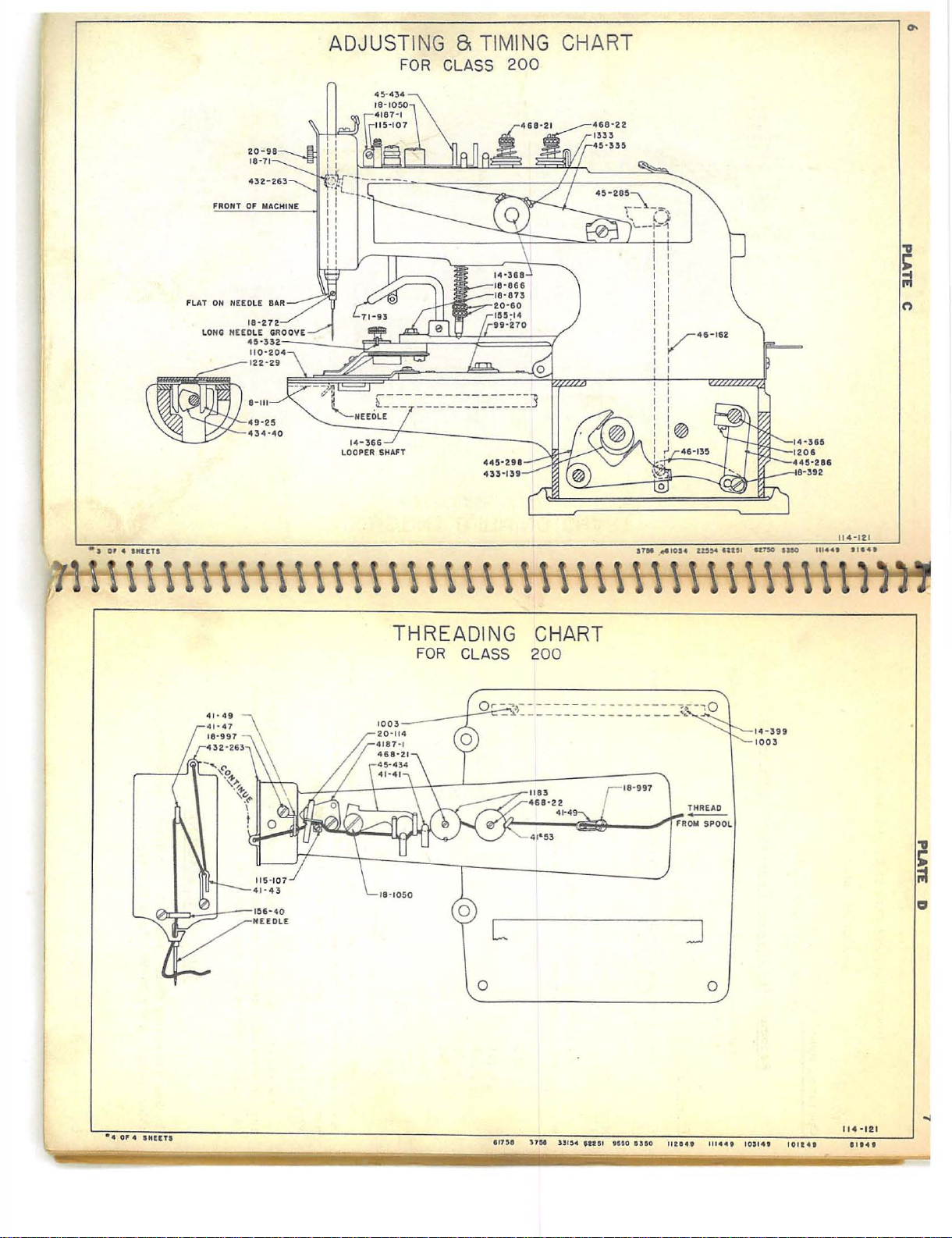
Threading
ess
prev
on
the
right
incurring
iously
Cha
nut
20-98,
to
change
the
manufactured.
THREA
rt,
Plate
Plate
obligation
DING
D.
C,
specifications
to
install
MACHINE
To
draw thread
Page
6.
or
designs
such
through
at
changes
ma-
Page 6
10
INSTRUCTIONS
L e
wis
produce
machine
of
side).
provided
or
the
buttons
ther
sewing
gauge
Plates 8 and
1.
when
extreme
an
26-163,
the
Model
Model
Model
Model 200-
Model
Model
NOTE:
is
the
clamp
However,
so
lengthwise
operation.
Fittings
you
description.
Other
special
buttons
for
spacing but
ADJUSTING
Adjust
machine
height.
inch
between
and
LEWIS CLASS
Models
200-1:
Z.00-2:
Z.00-3:
200-6:
200-7:
set
nuts, 20-1Z.8
following
8,16,
6,12,
8,16,
4:
6,1Z.,
8,16,
6,1Z.,
On
models
for
is
crosswise
on
that
the
of
the
for
shank
wish
to
fittings
away
9.
AND
is
in
When
the
the
front
Z.00-1,
two
models
clamp
arm,
sew. See
from
tons
TIMING
stop
back
Z.OO-Z,
stitch
and
and
and
and
and
and
200hole
buttons
for
See
on
position
this
edge
of
stop
FOR
depending
on
ADJUSTING
Z.OO
Z00-3
formations:
32
parallel
24
parallel
32
diagonal
24
diagonal
32
diagonal
24
diagonal
1,
Z00-2,
buttons
of
the
arm
200-6
and
motion
the
stop
has
can
are
available;
Plate 7 and
sewing
material
shirts and
STOP
Plates A and
motion
the
been
of
the
motion
AND
MACHINES
, Z00-
4,
stitches.
stitches.
stitche5.
stitches.
stitches
stitches.
Z00-3,
or
on
snap
MOTION
need
done,
head
plunger
Z00-4,
for
tacking,
(that
is,
200-7,
be
either
the
requirements
send
pages
fasteners,
with a shanking
dresses
B
plunger,
le bar ,
t h
ere
of
stop
lever,
TIMING
Z00-6
8t
.
when
the
from
side
adjustments
crosswise
samples
17
and
stay
are
shown
CLUTCH
Rod
71-92,
25-11,
should
motion
45-348
200-7,
the
motion
to
are
of
of
18
for fur -
buttons,
foot,
is
at
be
5/16
plunger,
.
on
so
shank
and
that
its
of
11
.....
~
~
.......
.......
.......
.......
.......
.......
.......
.......
.......
.......
Adjust
roller,
there
of
stop
stop
curely
the
machine
hexagon
lever
is
in
in
cam
and
the
machine
nut
Z0-34
For
turn
35-16,
NOTE: 1/32
35-16,
is
about
motion
motion
and
head
engages
stop
lever
thin
to
timing
stop
drops
trip
lever,
rides
3/32
plunger,
disc, 44-280.
see
that
is
in
screw,
the
position
so
that
section
check
•
stop
motion
in
relieved
11
cam,
Clearance
445-370,
on
periphery
of
an
there
this
position,
18-Z.80,
ball.
and
driving
there
of
lever
this
measurement.
motion
434-42,
inch
26-163,
Tighten
is
no
79-37,
is
cam,
portion
as
on
of
clearance
and
end
adjust
so
that
in
the
pulley
about
45-302.
have
clock-wise
of
shown
left
stop
the
the
play
the
driving
is
l/3Z."
the
side
motion
between
largest
clamp
in
trip lever
cam
thick
idling,
play
Note:
Lock
machine
until
cam
in
Plate
of
base,
acrew
lever,
portion
pulley.
adjust
between
hold
screw
at
"X"
B •
so
cam,
the
bottom
diameter
18-739
shaft.
45-30Z,
of
When
scr·ew
pulley
18-747
in
stop
trip
lever
•
that
434-42,
of
through
the
machine
ball
in
towards
with
position
roller
when
side
the
se-
While
cam
18-747,
79-37
and
,
.......
.......
.......
Z..
TIMING
BUTTON CLA
MP
CAMS
......
.......
......
......
......
While the
highest
until
pins,
ings
the
22-Z.38,
in
........
3.
.......
CHANGING
.......
.......
To
a
.......
.......
.......
.......
.......
Z7-189,
from
and
remove
the
.......
.......
the
.......
.......
.......
......
~
the
gear
removed.
ing
cam
replace
the
loosen
sub-base
Set
arm
Trip
worm
are
hold
To
assemble,
shaft
machine
position,
timing
in
the
base,
27-190,or
sub-base
the
the
shaft,
leaving
head
with
to
avoid
stop
motion
gear
backed
Remove
of
stop
is
spotted
is
on
Be
securely
by rem
set
screws,
the
end
and
14-364.
enough
two
screws
cam,
,and
in
set
the
sure
See
it
will
oving the
screw
sub-base
down
the
loosen
to
the
therefore
.oosen
lines
base.
then
BOTH ·BUTTON
or
change the
27-191,
two
remove
rear
bending
on
shaft
off
motion
reverse
stop
position,
screws in
cams
are
both
tighten
CLAMP
Plate
4
button
indicator,
434-42,
clamp
be
necessary
belt
1003,
18-816,
on
on
bench,
the
screws
Be
sure
prevent
inguidecollar
above
procedure.
,the
both
in
cams
the
CAMS
from
that
and
the
21-287.
the
burring
remove
cam
line
hold
table
with
needle
cams,
then
with
set
to
remove
the
hinge
lift
the
•
each
screws
the
39-107,
cam
The
must
the
clo.se
•
or
gears 27- 155,
driving
shaft
head
cam
in
shaft
shaft,
gear
are
screws
cams,
using a block
in
shaft
bar
at
turn
indicator
to
the
pulley
14-399;
from
under
and
the
when
and
by
14-364.
on
be
retim.ed.
its
cams
bear-
head
in
worm
it
tak-
the
is
Page 7
lZ
Refer
t o
Paragraph Z for
graphs 4 thru 8 following.
looper
the
and
4.
chines will
depending on
follows:
5.
s
629
justable
The
machine
Set
tighten
THREE
The
1.
2.
3.
SETTING
Make
ible
to
6.
SETTING
and
positioning
sides
of
next
machine back
set
screws,
COMBINATIONS
cams
and
produce
the
With
one
ton.
With
one
With
two
FOR
sure
that
in
relation
make
this
lobe
180-2
FOR
finger.
the
cains
to
the
on
gears
8,
16
model.
half
cycle
cycle
of
cycles
SIX
OR
latch
to
lever
adjustment.
so
that
TWELVE
timing
Refer
with
bearings
sub-base
1003.
OF
furnished
or
32
These
of
cain
of
cam
EIGHT
51-22
45-331.
gaps "X"
OR
the
cams.
to
Paragraph
timing
Set
cam
shaft,
shaft
Now,
marks
as
shown
on
and
assemble
guide
collar
STITCHES
with
the
stitches
combinations
is
SIXTEEN
or
shaft, 6 or 8 stitches
12
or
16
,
24
or
STITCHES-
moved
If
necessary,
using
and "Y"
upwardly
knob
STITCHES.-See
Also
refer
11
for
must
be
Plate
the
against
AVAILABL
Lewis
6,
32
Class
12,
or
are
obtained
stitches
stitches
See
loosen
142-6,
are
both
Plate
as
timing
mounted
A.
hinge
24
per
far
move
open
to
Para-
shaft
gear.
E
ZOO
stitches
per
button
per
B
as
screw
the
ma-
as
but-
button
pos-
18-
ad-
.
Plate
in
,
,.....
,....
~
......
.-...
e-i4
....,...
:t:
:t:
..-...
~
~
~
~
~
~
.......
7.
SETTING
Close
with
screw
lat
ch
51-22
not
disturb
factory
sary
relation
enough
c
am
adjustment,
the
wit h
far
8.
and
to
reset
to
434-42.
machine
screw
as
possible
TIMING
gap
t o
pass
FOR
"Y"
18-39
down
t h e
setting
does
screw
lever
over
The
as
it
will
18-629
and
SCREW
TWENTY-FOUR
See
using
Knob
at
the
bottom.
as
far
as
it will
of
screw
not
require
1170,
proceed
45-331
machine
is
bind. When
so
gap
"X"
possible
securely
lock
in
18-39
that
should
tightened,
position
-
See
OR
Plate
142-6.
Loosen
go.
1170.
adjustment.
as
this
lever
on
every
be
turned
to
move latch
this
latch
with
Plate
THIRTY-TWO
B
See
that
machine
screw
Tighten
This
follows.
second
has
bring
B
If
raises
nut.
scre
screw
it
does
revolution
by
51-22
been
screw
18-629
is
Set
lever
hand
down
set
STITCHES
is
a.
w
18-629
set
become
latch
445-370
to make
so
properly
117
0
nd move
at the
51-22
of
down
stopped
.
Do
neces-
the
this
far
that
and
as
13
in
.......
Remo
ve
hand
knob
.......
.......
......
.
~
screw
until
shown
18-619.
scr
ew
on
Disengage teeth of
18-39
Plate
B.
57-23.
is
on
top
Reassemble
and
Remove
gear
the
machine
parts
lever
45-331
27-170
is
removed.
and
in
turn
the
by
taking
on
position
out
shaft
.......
.
.......
9.
ADJUSTING
DEPTH
OF
NEEDLE
BAR
......
......
.J.,..
........
.,...
.,-.
.,_.
:t:
B
-;--
.-......
Insert
needle
upper
or
marks.
that
that
the
is
the
bar
set
of timing
in
the
Long
When
needle
the
needle
needle
at right angles
needle
needle
as
far
using
cla
mp
bar
is
directly
in
as
with
clamp
and
to
needle
it will
marks.
Short
lower
screw
screw
the
th e
Shank
does not
flat
looper
in
front
bar,
go.
When
set
18-272
on
of
the
of
making
When
series,
timing
shaft. See
the
using
strike
is
bottom
machine
sure
using
use
on
it
short
needles
low
marks,
needle
the right
side
of
that
.
is
er
be
bar
the
up
needl
in
set
the
the
careful
hand
long
into
the
es, use
long
of
timing
bushing.
side
nee
dle
groove
series
to
of
bar
see
See
in
Proceed
180-2
gap "X"
so
that
at
the
as
gap
in
Paragraph
"Y"
top
in
is
order
5,
closed.
to
except
do
Machine
this.
move
adjustable
must
be
lobe
stopped
with
:t
:t:
J,...
.,_...,.
.......
10.
ADJUSTING
The
the
needle
justment
screw
needle
and
can
18-750
NEEDLE
guard,
adjusted
be
made
.
GUARD
8-111,
for
through
should
the
various
the
hole
be
set
sizes
in
the
as
close
as
possible
of
needles.
needle plate,
The
using
to
ad-
Page 8
14
11.
ADJUSTING
AND
LOOPER -See
Turn
the
has
reached
has
risen
iri
the
set
cam
34-47
so
that
timing
and
tighten
til
positioning
g9.
Now· rotate
ger
is
as
cam
until
sandths
porarily.
needle, and
looper
er
possib
the
Tighten
12.
45-332
ton
an
indicat
by
needle
of
Rotate
sleeve
in
loope~
le
without
Loosen
timing
screws,
ADJUSTING
TONS -See
Insert
so
to
move
eig
hth
or
Turn
machine
loosening
passes
AND
hand
its
lowest
about
3/32
being
used. Loosen
and
in
mark
screws
finger
rear
far
forward
positioning
an
inch,
looper
tighten
is
against
sleeve
touching
screw
mark
coincides
making
BUTTON
Plate
button
that
of
21-287
in
button
slightly.
an
inch
on
the
two
through
TIMING
Plate
wheel
in
po~?ition,
of
an
looper
sleeve
in
over
sleeve
coincides
in
three
yoke
positioning
as
it
finger
and
then
until
screws
positioning
so
that
rear
sure
A
jaws
is
loosely
If
the
apart,
I/8
graduations.
slowly
hexagon
the center
THREAD
B
the
proper
inch;
screws
70-50.
with
point
has
moved
will
go.
clears
tighten
point
in
looper
looper
it
and
tighten
positioning
with
timing
that
CLAMP
of
button
held
holes
set
pivot
by
head
and
that
timing
cam.
finger
the
comes
cam
TO
clamp
in
hand
screws
of
POSITIONING
direction
continue
is,
to
in
rear
Set
Rotate
to
the
cam
Now
adjust
needle
one
screw
of
looper
sleeve,
finger
as c.lose
looper
finger
mark
is
against
SEW
and
by
jaws,
the
button
indicator
and
each
hole
to
the
second
positioning
three
mark
left
until
about 5 or
in
is
making
cam.
screw.
cam
on
FOUR
adjust
permitting
155-14
adjust
18-873
of
until
the
turn
until
point
on
looper
three
point
as
far
positioning
positioning
rear
in
center
sure
Now
to
needle
and
rotate
looper
looper
HOLE
stop
are,
for
and
the
button
so
that
the
button
FINGER
needle
needle
timing
finger
cam
sleeve
cam
as
it
10
cam
of
that
adjust
sleeve.
sleeve.
BUT-
lever
the
example,
spring
the
.
mark
434-40
will
fin-
finger
thou-
tem-
loop-
as
until
but-
clamp
un-
~
~
.,.;..e
...-..
.,.;..e
........
~
.......
.......
.......
........
.......
.....-..
~
__.....
.......
.-....
.......
.......
~
...-..
.......
......
~
....-..
..-...
..-....
.......
.......
.......
~
.......
~
.......
.......
......
.......
:t:
~
:t:
......
.......
.......
The
figures
may
be
13.
TWO
See
dicator 2 l-.287
button. Use
of
button
holes
14.
ADJUSTMENT
Lever
ated
by
the
cut-out
the
final
15.
ADJUSTING
Adjust
71-93
rearward
pin
is
cannot
16. ADJUSTING
The
and
is
and
locked
17
. A.
The
3/64
of
when
the
on
necessary
HOLE
that
button
indicator
clamp
in
the
button.
445-.286
eccentric
in
stitch.
vertical
by
about
position.
to
prevent
strike
pre
ssure
regulated
by
DJUSTING
thread
an
inch
thread
the
indicator
to
BUTTONS
clamp
on
circle
so
that
should
on
vertical
HEIGHT
1/32
overtnrow
the
needle
PRESSURE
on
by
the
lower
THREAD
nipper
between
nipper
deviate
FOR
main
rod
of
Check
the
the
4187-l
is
adjusted
with
155-14
the
needle
RAISING
be
shaft,
link
46-16.2
OF
71-73 so
an
inch
stop
of
.
button
upper
knurled
NIPPER-
it
and
is
open.
plates
slightly
two
dots
only
will
BUTTON
adjusted
just
as
BUTTON
that
when
pin
the
button
ON
BUTTON
clamp
knurled
nut.
should
the
thread
are
only
from
the
as
in
Paragraph
which
to
adjust
enter
so
that
clears
this
link
CLAMP -See
the
roller
the
button
22-2
73.
clamp,
CLAMP -See
should
nut
20-60
See
Plate
be
adjusted
nipper
approximate,
figures
represent a two
sidewbe
in
the
CLAMP -See
lever
the
is
The
be
•
12.
movement
center
445-298
lower
moving
Plate
35-17
clears
clamp
B
is
purpose
so
that
moderately
on
acrew
so
that
block
115-107
corner
the
there
and
Set
of
the
Plate
oper-
over
B
in
its
of
this
button
Plate
light
18-866
15
it
in-
hole
C
of
on
rod
B
ls
Page 9
16
18.
AUTOMATIC
The
on
tension
clamp
vent
follows:
is
highest
needle
the
the
Turn
moving
rection
sion
staff
When
thread
19.
THREAD
The
the
automatic
this
regular
threads.
The
fore
the
~ease
the
This
adjustment
lever
45-32.7
ZO.
THREAD
The
eno
ugh
cycle
so
made.
off
so
when
completed
thread
staff
thread
looper
the
machine
upwards
position.
bar lever
until
the
468-Zl.
this
setting
tension
regular
thread
Normally,
opener
end
of
thread
to
purpose
thread
that
the
This
much
thread
THREAD
tension
468-Z
tight until
from
and
Loosen
45-335,
thread
Tighten
release
TENSION
thread
thread
tension
for
the
each stitching
at
the
is
made
open
TAKE-OFF -See Plate
of
through
first stitch
lev
er
should
that
.
TENSION
release
1,
and
requires a moderate
the
stealing
in
has
tension
only a light
the
thread
the
proper
is
from
the
and
is
released
both
been
requires
tension
may
regular
time
the
by
tension
take-off
the
tension
be adju
tails
thread.
two
turn
release.
loosening
of
operates
looper
5/16
hexagon
screws
properly
no
staff
require
tension
thread
cycle
button
discs. See
the next
of
thread
RELEASE-
the
has
This
direction
to
3/8
shaft
14-368
by
the
1333.
made,
further
468-2.2.
As
adjustment
is
tension
.
It
should
clamp
screw
B.
lever
at
the
stitching
sted
so
are
tension
taken
the
tension
until
of
an
head
screws
in
tension
the
adjustment.
is
mounted
in
any
required.
operates
be
starts
18-750
Plate
45-434,
end
of
that
it
left
See
Plate
discs
tight
tension
loop,
is
timed
the
needle
inch
from
1333
the
proper
discs
on
automatic
behind
sewing
adjusted
one stitchin
cycle
does not
on
B.
for
to
and
is
the
machine,
different
just
raise.
sliding
to
may
button
C
mounted
to
to
pre-
as
bar
its
in
the
di-
ten-
be-
to
re-
pull
g
be
pull
.......
......
.......
......
__...
~
.......
....-.
~
~
~
......,.
~
.......
.......
~
...-..
......
~
~
......
~
......
~
......
~
~
~
......
......
......
.,.....
~
~
.,_...
.......
~
......
~
::t:
.,_.
+
This
block
Zl.
TWO
In
the
clamp
Connect
bearing
from
the
of
vertical
machine
In
some
The
obser
ved
ZZ.
NEEDLES
Use
must be
graph
Z3.
FOOT
An
This
second
to
the
chain
from
e
nd
of
Plate
C. A hole
this
chain
sewing
thread.
button
lever
115-106
TREADLE
case
it
and
link
screw
second
link
thru
general,
cases,
following
when
long
reset
9 .
TREADLE
additional
left
of
this
the
vertical
may
shank
The
clamp.
is
adjusted
in
the
appropriate
OPERATION
is
desired
thus
use
46-135
which
buttons
needles
treadle
it,
buttons
second
to
18-392.
46-162.. A hole
buttons
sewing
using
be
but
treadle
the
SHANK
as
is a description
for
the
foot
treadle
should
in a position
second
link
is
provided
attached. Note
still
foot
by
loosening
direction
-
to
eliminate
two
foot
treadles,
the
f~ont
hole
do
not
loosen
is
attached
is
provided
chain
may
be
BUTTONS -See
up
to
50
!ignes
large
as
55
of
shank
buttons
sewing
lower
treadle
46-162.,
treadle
set
is
be
placed
convenient
in
uses
shank
used
is
attached
that
the
that
the
is
of
base
automatic
for
screw
See
the
in
lever 445-2.86. Move
screw
to
the
passed.
can
!ignes
the
.
buttons.
timing
for
beside
for
lifts the
of
the
the
18-750
along
Plate
automatic
proceed
12.06.
hole
in
in
the
Plate
be
handled,
can
be
important
marks.
sewing
the
the
to
the hole
button
the
machine
normal
lift
purpose
the
C
raising
as
the
base
7
sewed.
points
The
shank
main
operator.
clamp.
set
to
break
of
and
nipper
follows:
The
lower
of
although
needle
See
Para-
buttons.
treadle
in
the
thru
ting
opening
moving
bar
of
chain
end
the
to
be
bar
The
lower
See
which
for
the
17
•
in
and
the
:t:
I
Page 10

18
24.
HEIGHT
A:n.
operator
when
theo
ing
the
To
button
ed
on
the
machine.
25. ADAPTERS,
There
clamps
tons . A
Unless
ple
buttons
ju
st
what
26.
FEED
The
there
is
the front
21.
SETTINP
OF
adjustment
can
open
machine
block
115-127
guard
against
strikes
button
See
are a great
and
work
different
the
correct
should
is
required.
PLATE
feed
plate
slightly
edge
BUTTON
is
the
has
the
needle,
clamp
Plate
CLAMPS
support
set
be
for
less
of
the
FOR
provided
button
stopped.
mounted
the
lifting
B.
many
may
number
sent
sewing
than 1/64
opening
Models
SPECIAL
SIX
OR
CLAMP -See
for
controlling
clamp
with
This
on
the
button
there
AND
different
blocks
be
required
of these
to
the
in
EIGHT
clamp
is
an
lever
WORK
available
agent
shank
of
an
the
work support
Z00-6
INSTRUCTIONS
STITCHES-
Plate
B
the
the
second
adjustment
front
of
the
being
raised
adjustable
on
the
rear
top left
SUPPORT
combinations
for
sewing
for
different
parts
is
known,
so
that
he
buttons should
inch
between
and
200
- 7
See
amount
foot
is
made
machine.
so
stop
42-21
BLOCKS
of
shank
shank
several
can
determine
be
the
block.
Plate
the
treadle
by
mov-
high
that
mount-
of
the
adapters,
but-
buttons.
set
so
needle
12
sam-
that
and
the
:J::
:f
~
.,_.
:E
:E
._!-.
.,.;..e
~
:f
~
~
.......
~
:r:
..-!'4
~
........
......
~
......
a.
Plate
two
hole
b.
Plate
sired
NOTE:
the
machine is
29.
SETTING
Pull
tor
21-287
To
set
4110-329
button
To
set
4ll0-329
spacing
Adjustment
slide
and
the
clamp
all
the
position.
the
clamp
all
the
.
of
in
normal
MACHINE
plate
4110-329
indicator
motion
way
motion
way
slide
155-14
out.
Use
in.
stop
FOR
crosswise
Put
indicator
lengthwise
Use
plate
position.
FOUR
all
the
for
spring
spring
4ll0-329
HOLE
way
desired
of
the
arm,
indicator
155-14
out,
for
of
the
a r
indicator
must
only
BUTTONS -See
and
use
spacing.
pull
21-287
desired
m,
push slide
21-287
be
spring
slide
spacing.
for
made
iri
the
de-
when
Plate
indica-
19
12
:!:
not
Refer
used
to
when
Paragraph
sewing
5 Pa
four
ge
hole
12.
NOTE:
buttons.
Six
or
eight
stitches
are
..-...
2
8.
SETTING
TACKING-
The
or
lengthwise
motion
MACHINE
See
Plate
of
the
clamp
of
the
arm
FOR
lZ
:
can
TWO
HOLE BUTTONS AND
be
set
so that
it
is
either
FOR
crosswise
..-.....
:t:
I
Page 11

CLASS
200
0
"'
"D
s
"'
...
\\\\\\\1\\1
~\\\\\\\\\\\
CLASS
200
\1\\1;;
114-84
\tt
4
IN
GEAR
27•189
"D
s
"'
......
&&
..
111141 101141 IOS4t
114-
ll14t
Page 12

18-330
20-98
41· 47
CLASS
200
I'll
I'll
.,
s
"'
w
CLASS
200
L----;co~•••••~•~tut;,;.--
----------------
----
----------
------
----------
----------------
----~~
------------------
----------~--------------~l:~~_j
1
11'5
1 I
141
~
Page 13

CLASS
200
•s
OP I IMI!TS
\ \
41
•49
\\\\\\
\
\\\\\\\\\\
CLASS
200
\
----
112141
111441 I
OS
I4t
\\
FROM
21·287
1
41·3
110·206
21·321
12
787
45·
1160
~~--~~~
14·399
32
THRE
35
333
·1 9 1
\\t
AD
SPOOL
SPRING
..
·
Page 14

----
--
~==~------
11
5·1~3
115·151
CLAMP
18·733
22·224
------
----------
SHANK
4~
430·55
430·61
USE
F
OR
STO.
FOR
MUST
NEEDLE
THE
LOWEST
LOHG
SHANK
29·14L
29•16LSS
29·18LSS
29·20LSS
430·62
CLEAR
BAR
NEEDLES
BUTTONS
----
------~~----------------------
BUTTON
CLASS
PARTS
200
aflrSi
BUSHING
WHEN
1 i
~~
)h. ....
IS
SET
USING
LINES
OH
.,.,
18·330~
17·155
18·750
.
•
BAR
.
L.J.
1
1r
' -··-----
'""'
---··---
-·~----
39
95
9o-34
'~~
90·6
;~:~~:
··-
- ·
---
71·
72
835
-
-{_5·17
_ ____/""""-
1005
21·317
20·60
18·965
99•308
..
.__
__
_
••
)
1
9o-49Jt®
AOJUSTA8LE
.-
90·47
00
/8-
490·49
--~
132
.,
§;;
AOAP~R
-t
"'
...
~
45-4
19
\\
\\1\
\\\1\
158
-25
158-21
18-75
1
8-125
45-458
18-931
45-332
99-316
99-316-1
18-930
\\\\11\\\\\1
($~
(t\~
114
- 123
1\\t
110&0
.,
>
itt
CD
430-77
SNAP
FASTENER
CLAMP
430-86
HOOK 8
EYE
CLAMP
72258
611158
114-176
37118
N
~
Page 15

475-231
BUTTON
SHEET I OFI
SHANKING
FOOT
424-299
NECKING ATTACHMENT
18-986
CLASS
99-
STAY
Blr'f'i'ON
24-304
313-
200
HOLDER
GAUGE
GAUGE
72258
407-10
FOR
SPACING
(LEFT SIDE)
407
-11
FOR
SPACING BUTTONS
(RIGHT SIDE)
7258
BUTTONS
37'SS
U!!4
114-150
82551
TACKING
MODELS
MODELS
CLAMP
1
22-46
200-1,
200-6.200-7
(MODELS
200-2,
COMPLETE
200-6,
200-7
WITH
ONLY)
200-3,200-4,200-5
USE
TACKING CLAMP
THREAD
USE
TACKING CLAMP
430-75-1
BREAKING
430-75
FINGER
114-162
,
§
...
0
Page 16

0
""'
THREAD WIPER FOR
BUTTON SEWI
LEWIS
NG
MACHINES
200
INSTRUCTIONS
SET
ROD
oF•
19/32"
SET
STOP
CLA"P
ADJUST COLLAR
SO
LOOP
NEEDLE. TIGHTEN SET
ADJUST
BACK
IN
FRONT
SEW
ONE
TO
CHECK
IB•I
THREAD
WIPER
CLASS
FOR
71•99
TO
FR~
42·21
AND
WILL NOT
OH
SPRI
WIPER
FORWARD
OF
LOOP
ON
Of
THR
OR
TWO
ADJ
UST
036
ASSEMBLY
(INCLUDES
ADJUSTING
LIFT
CLAMP
FEED
PL ATE,
STOP
OVERTHROW.
39·C255
HG
21·~11
SCREW
WIPER
SPRING
EAD,
BUTTONS,
..
ENT,
BEFORE
BOP
TO A MAXI"'U"'
PIN 22·
WHEH
CLA"P
IS 3/ 81 TO
IN
OR
BACKWARD SO
21·411 PASSES
TURNING
SEWING
68·29
3~79
21·411
No.
71·99)
THREAO WIPER
273
SO
IS
DOWN,
RIGHT
"ACHIHt:
BY
OF
MANUALLY
POWER.
COLLAR.
44!!-432
...
...
MODELS
200-6
AND
200-7
10·
114
\tt
30 4
-170
1
75S
"a
s
"'
..
N
S
HU:T
I C# I
61751 lltn
114
· 1
tll0~4
J28S4
64
Page 17

33
Part
No.
5-5Z5-ll/3Z
7-10
7-11
8-111
8-1Z6
8-13Z
14-36Z
14-363
14-364
14-365
14-366
14-368
14-399
14-455
BUTTON
MODELS
Plate
9
9
9
1,4,5
4,5
7
Z,4
1,Z,4,5
l,Z,4,5
l,Z,4,5
l,Z,4
l,Z,3
1,3,6
7
PARTS
Z00-4,
LIST
SEWING
Z00-1,
Z00-6
Shanking
Gauge
Gauge
Guard
Guard
Shaft
St
for
for
for
for
71-9Z.
Adjustable
for
Pulley
Cam
Shaft
op
Motion
Looper
Shaft
for
Hinge
Shaft
Covers
Shaft
for
Opening
FOR
ZOO-Z,
and
Foot.
spacing
spacing
Needle,
stop
Guard
lift
Shaft
in
Shaft
Needle
3Z-191
holding
Lever
LEWIS
MACHINES
Z00-3
Z00-7
Description
buttons,
buttons,
in
motion
for
lever
445-Z98
in
base.
base.
T r
ip
Lever
in
base
.
Lever
in
both
sides
and
3Z-19Z.
Shank
45-37Z.
left
right
cylinder
plunger
90-49, 90-54.
45-335
Button
Shaft
of
base.
rod
in
base.
in
Sub-base
Clamp
hand.
hand
base.
in
arm.
.
for
16-Z88
16-Z89
16-Z90
16-Z91
16-Z
9Z
16-Z95
16-Z96
16-Z97
1'6-315
4
4
4
4
1,4
1,3
Z,3,6
Z,3
Bushing
Shaft
14-363
Bushing
Shaft
14-363.
Bushing
Shaft
14-364.
Bushing
Shaft
14-364.
Bushing
Shaft
14-366.
Bushing
14-368.
Bushing
Z5-ll.
Bushing
Z5-11.
Bushing
15. Sold
43Z-Z63
in
right
.
in
left
side
in
right
in
left
side
in
front
in
arm
(Upper)
{Lower)
in
Cover
Assembled
only.
side
of
base
of
base
side
of
base
of
base
of
base
for
for
Needle
in
arm
for
in
arm' for Needle
43Z-Z63
in
Front
for
for
Looper
Lever
Needle
for
for
Pulley
for
Cam
Bar
Cover
Pulley
Cam
Shaft
Bar
Bar
138-
Page 18

34
Part No.
16-334
17-124
17-147
17-155
11-1
n 2
18-39
18-71
18-75
18-125
l8-Cl86
18-272
18-280
18-286
18-307
18-318
18-330
18-391
18-392
PARTS
BUTTON
MODELS
Plate
4
1,5
4
7
1,4
2,3
5,8
8
11
2,3
4,5
2
7
10
1,2,3,
6,7
2
1,2,5
200-4,
LIST
FOR
SEWING
200-1,
200-6
Bushing
14-366.
Bearing
Plate
Link
Stud
in
Positioning
base.
Stud
for
Opening
Stud
for
Hinge
Screw
in
stop
base.
Screw
of
Screw
40
Hinge
Flat
430-77,
Screw
Screw
Screw
Hexagon
45-348
Screw
Screw
block
Screw
122-45
Screws
and
Screw
clamp,
Screws
50,
Shoulder
base, and
base,
to
Button
to
for
in
in
for
Needle
Screw
for
for
in
in
for
for
for
and
for
for
Shank
for
arm.
LEWIS
MACHINES
200-2,
and
in
Stud
Lever
holding
Block
Cover
motion
for
Clamp
Needle
Scr
Feed Plate, Shank
Front
Screw
200-3
200-7
Descriftion
rear
of
in
top
46-137.
445-349
Finger
Shank
115-12
432-202.
for adjustable
cam
side of
stop
Stud
46-137
lifting
clamping
Bar 2 5-11.
for
Clamps,
430-86
110-404.
Collar
ew
for attaching
motion,
Covers
attaching
holding
122-46
Stop
42-21
End
17-155
buttons.
cap
of
for
Gear
Stop
Bar
on
base
of
base
122-29,
7,
434-42,
27-170
lever
Bearing
Lever
Snap
.
39-C255.
25-ll, for
32-198
work
thread breaking
to
Clamp
on
Cover
for
Top
Ball
46-135
top
for
for
Roll
Button
in
front
45-331.
Fastener
right
on
sup
Lever
432-263.
opening
and
of
base.
Looper
for
Slide
35-20
in
cylinder
Clamp
of
shoe
left
side
on
Block
45-332,
Needle.
45-302
side
side
porting
Buttons.
30-75.
45-285
Joint
46-175
Shaft
arm.
or
left
117-
Clamp
of
of
arm
fingers
button
4124-
for
lobe
of
side
on
to
base
in
~
~
~
ri-4
~
:r:
Part
No.
PARTS
BUTTON
MODELS
Plate
200-4,
LIST
FOR
LEWIS
SEWING
200-1, 200-2,
200-6
MACHINES
and
200-3
200-7
Description
35
.......
.......
~
r:4
~
~
18-547
18-562
18-619
.-i'1
~
~
~
...;-.e
..-!4
~
.......
18-623
18-629
18-634
18-677
~
18-730
~
..;-e
.,...
.
~
~
~
18-733
18-738
18-739
18-747
18-750
1,5
1,5
7
1,5
6
2,4,5
7
3
1,4,5
4,5
1,2,4,5,
& 7
Set
Screw
Bearing
Screw
arm.
Shoulder
46-138
Shoulder
162
to
Shoulder
side
of
Screw
on
Shank
Screw
latch
Screws
40,
in
Screws
Bracket
Allen
l
for
2
for
2
for
Grooved
2
for
1
for
Spiral
2
for
Spiral
Screw
Screw
Clamp
445-370,
Screw
Clutch
Screw
Nipper
for
adjusting
thread
Arm.
Screw
Tension
Screw
inder
in
Pin
for
Lever
Screw
on
top
screw
lever
Screw
base.
in
Collar
Button
in
Lever
51-22,
for
cylinder
for
50-215,
Set
Screw:
Lower
Worm
Worm
for
Clamp
in
Sub-base
Screw
on
for
adjusting
Pressure,
for
clamping
Operating
pull-off
for
adjusting
Disc
for
Needle
Base.
rear
of
22-219.
445-405,
for
of
base.
for
445-405,
for
39-95
Clamp.
45-331
left
aide
positioning
base.
Stop
Motion
on
Ball
Eccentric
27-189.
Collar
Gear
27-155.
Gear
27-169.
Gear
27-168.
for
for
for
Stop
left
side
right
Bar
block
115-106 for
Lever
on
468-22.
Guard
base
for
left
Links
46-136
connecting
on
left
Lever
Sub-base.
45-331
for
Spring
for
of
base.
Finger
TriP.
39-
107.
Shank
But
ton
Motion ·Trip
of base
Lev
er
45-302
aide
block
4115-104
138-15,
445-304
lever
45-327
8-111
holding
side
Link
side
clamping
Cam
Lever
33-137
Buttons.
Tray
.
of
base.
and
adjusting
on
top
to
in
Cyl-
of
and
46-
of
arm.
on
left
21-353
434-
.
4186-1,
Lever
{or
to
Screw
of
ope
n
Page 19

36
37
Part
18-750
18-752
18-766
18-800
18-809
18-812
18-814
18-816
18-818
18-819
18-821
18-823
18-826
18-827
18-835
18-854
18-866
18-873
No.
PARTS
BUTTON
MODELS
200-4,
Plate
1,2,4,5,7
2,3
12
4
2
3,4
1,5
3,6
1,5
4,5
6
1,6
1,4
, 5
1,2,6
1,2
2,5,7
LIST
SEWING
ZOO-I,
200-6
Screws
206
to
Screw
Screw
nipper
Screw
17-155,
Screws
4115-194
Knob
Screws
base
.
Screw
458-39.
Screw
vertical
Screws
190-1
Screw
Screw
Screw
slide
Spot
Screw
Lever
Screws
Screw
Nut
20-114.
Screw
left
side
Screw
for
front
Arm.
Screw
for
stop
Screw
on
top
Screw
Clamp
Screws
Clamp
FOR
MACHINES
200-2, 200-3
and
200-7
for
attaching
Base.
for
guard
for
holding
bar.
for
holding
for
Shank
for
holding
to
nipper
Screw
plate
for
for
block
for
grease
connecting
link
46-162,
to
attach
to
cylinder
for
Cam
for
locking
for
clamping
158-9,
for
45-348,
for
attaching
Stud
for
Top
for
spring
of
Arm.
on
Nipper
end
of
for
clamping
motion
for
Thread
of
arm.
for
adjusting
Holder
to
attach
Holder
LEWIS
Description
Indicator
8-111.
Lever
Block
Buttons.
blocks
bar.
right
side
115-137,
hole
in
curved
in
Base.
insert
for
base.
Roller
Stop
right
opening
Spring
434-42, left
99-270,
99-270.
35-15,
machine
Indicat~r
on
cylinder
Motion
side
Arm
Nipper.
front
of
Zl-379
Bars
138-15
Zl-3
adjustable
Nipper
pressure
under
Button
Clamp
45-327
115-127
115-106
Cover
top
Clutch
link
46-135
Looper
in
to
sub-base.
155-14
Plunger
of
base.
to
Base.
Arm.
in
block
and
79,
side
Block
on
Arm.
Plate
to
to
3Z-198.
rear
Pulley,
base.
base
Take
115-110,
138-ZZ
left
Shoe
of
115-107,
Button
to
Button
ll0-
Stud
and
of
to
Yoke
to
s
side
180-2
base.
of
~
..,.;..e
__.
__..
..-..
~
....:--
.......
~
__.
........
.-.
~
.....:-e
~
....:--
__.
......
~
......
__.
.,......
.......
~
..-.
......
.......
.......
.......
.--
.--
.......
__.
........
........
......,.
~
...:--
:f
Part
18-873
18-878
18-907
18-920
18-92
18-929
18-930
18-931
18-934
18-945
18-949
18-958
18-959
18-
965
18-966
18-967
18-968
1
8-969
No
5
PARTS
BUTTON
MODELS
200-4,
•
Plate
1
1,4
2,3
5
2,4
5,8
5,8
5,8
4
5,8
4
4
7
2,5
4
2,4
4,5
LIST
SEWING
200-1,
200-6
Screws
Shank
Bearing
side
Screw
up)
Screws
Cap
base.
Hinge
Flat
Clamp
Bearing
158-Zl
Fastener
Shoulder
158-21
Fastener
Shoulder
Lever
Knurled
L
ever
Snap
430-86.
Screw
er
36-18,
Spot
right
Screw
Pawl
side
Screw
Button
Screws
top
of
Allen
44-280
Spot
Screw
33-137,
Allen
434-42,
FOR
MACHINES
200
and
for
Button
Screw
of
base.
for
41-47,
for
Screws
Screws
Button
430-77,
Screws
in
Flat
Clamp 430-77,
Screw
in
Flat
Clam
Screw
445-349,
Screw
45-332
Fastener
in
Collar
in
Screw
for
side
of
for
Stop
166-7
of
base.
for
regulating
Clamp.
for
Graduated
Cylinder
Set
Screw
.
for
in
bas
Set
Screws
left
LEWIS
-Z,
200-3
200-7
Description
attaching
Clamp.
for
clamping
to
Needle
Needle
for
Ball
for
Clamps,
and
for
Button
for
Button
p, 430--77,
for
in
for
on
Flat
Clamp
1284
front
Stop
base.
Motion Lat
in
steel
Base.
for
Needle
e.
(2)
side
of
Bracket
Gear
Thread
Bar
Plates.
Joint
45-346
and
in
Clamp
Slots
Clamps,
Slide
Clamps,
positioning
cylinder
clamping
Button
430-77,
for
end
of
Motion
disc
Pressure
Plate
Stop
Drive
for
Stop
base.
27-171,
Guide (Take-
25-11
4124-49,
and
in
Snap
430-86.
of
Slides
Clamp
Blocks
Clamp
base.
adjusting
Clamps,
clamping
Cylinder
Disc
ch
51-20
44-280,
110-205
Motion
Eccentric
Motion
50-238
on
•
45-347
Fastener
Snap
430-86.
158-11,
Snap
430-86.
finger
Clamp
Base.
44-280,
on
on
Shank
Disc
on
left
in
in
158-ll,
Loop-
and
right
on
Cam
~
~--------~-----------=~------------~~
Page 20

38
Part
18-974
18-982
18-984
18-986
18-987
18-995
18-996
18-997
18-1022
18-1023
18-1036
18-1050
20-13
20-34
20-35
20-60
20-80
No.
PARTS
BUTTON
MODELS
200-4,
Plate
1,2,3,6,9
4
4
9
9
1,6
2
2,6
12
12
11
1,2,6
1,6
4,5
2
1,2,6,
&:
7
z
LIST
FOR
SEWING
200-1, 200-2,
Z00-6
Screws
End
for
Screw
Screw
from
Set
Cams,
Screw
5-525-11/32.
Screw
5-525-11/32.
Screw
Nipper
Allen
Models
Collar
Screw
41-49.
Link
Bearing
446-173.
Screw
Bearing
Nuts
4187-l.
Nut
Lever
Lock
Knurled
Tension
top
Nuts
pressure
under
Nuts
Spring
Nut
lock
and
for
Cover
spacing
in
to
turning.
Screws
in
for
for
for
4187-l.
Set
200-2
39-131.
for
Locking
Screws
for
Screw
for
for
Adjusting
45-302,
Nut
Nut
Springs
of
arm.
for
arm.
for
for
on
top
Ball
MACHINES
424-299.
keep
base.
Screw
Screw
for
adjusting
on
Screw
Joint
LEWIS
200-3
200-7
Description
Thread
432-263.
buttons
Friction
for
Button
clamping
Positioning
Spring
Thread
Thread
sewing
of
21-366
for
and
200-4,
Guides
Screw
for
Wiper
for
18-995
Screw
on right
Stud
17-172
for
adjusting
21-284
Spring
Button
18-965
Shank
Connecting
4124-50.
Snubber
Screw
407-10,
Disc
Clamp
Shanking
Shanking
Worm
on
top
Links
45-434.
in
side
and
Clamp
for
156-40
for
407-11.
44-288
Vibrating
Foot
for
Thread
27-190
and for
41-48
of
base.
46-173
Spring
Nipper
18-747
of
.
Thread
113Z
21-317
Holder,
P r
essure
Buttons.
Rod
71-74
Gauge
Foot
and
and
Clamp.
for
base.
on
for
on
on
to
~
~
.......
......
.-.
....r1
~
.-f4
.....:---
~
~
~
~
.,..
..-r
..,..
_..r4
~
.......
~
......
~
...-...
......
~
~
~
..;-e
~
..;.--
...;-e
:t:
:t:
..,;..,e
......
~
....;..-
~
.,...
.-....
Part
Z0-81
Z0-98
Z0-109
Z0-114
20-123
20-127
20-128
21-70
21-96
21-229
21-Z8
21-Z87
21-295
21-310
21-315
Zl-317
21-321
No.
4
BUTTON
MODELS
Plate
2
l,Z,3
&:
6
1,Z,5
2,6
5,8
4
4,5
12
1,6
4
l ,Z
1,2
,5,
6,12
3,6
l,Z
5
1,2,
7
6
PARTS
Z00-4,
Slotted
Snap
430-86.
Nut
98Z
Nuts
aide
Spring
Spring
45-285,
Spring
releasing
Thread
Tension
Handle
136
Button
Spring
32-192.
Spring
on
Spring
Clamp,
Clamp
Spring
Clamp
arm.
Spring
tion
LIST
FOR
LEWIS
SEWING
Z00-1, Z00-2, Z00-3,
Z00-6
Nut
(left
necting
4124-49.
Knurled
for
releasing
ver.
Fulcrum
Plate,
Nut
on
Nipper
Flat
Button
for
in
of
to
top
on
and
hand
Rod
Thumb
Nut
on
top
Screw
.
Nut
Fastener
locking
steel
for
Stop
base.
for
ball
for
Button
in
in
end
clutch.
Tension
Staff
and
regulate
Clamp
for
holding
for
Thread
of
arm.
for
closing
Snap
430-86.
for
regulating
Holders
for
Lever
sub-base
MACHINES
Z00-7
Description
thread)
71-74
Nut
Thread
for
of
base.
Stud
for
locking
Clamps
Clamp
Screws
Disc
Motion
79-31.
rear
left
of
Pulley
Spring
468-21
Indicator
lengthwise
on
Fastener
99-270
45-333
•
to
on
Button
18-8Z3
430-63
44-280,
Clamp
side
on
Spring
rear
Covers
Nipper
Jaws
pressure
on
lock
Plunger
Nipper,
Clamp
screw
430-77,
18-959
Rod
Lifting
of
Shaft
(front)
top
of
arm.
of
Clamp
and
to
bottom
Ball
Joint
in
Slide
for
opening
18-931
and
430-63-1,
Clamp
and
for
Stop
71-92,
arm.
14-363
in
of
arm
on
Link
movement
32-191,
Block
115-107,
Flat
Button
430-77,
on
99-308,
trip
stop mo-
of
Con-
Z6-147
front
18-
Motion.
right
Lever
for
Thread
•
46-
Button
under
39
co-
in
of
~
Page 21

40
Part
No.
21-322
21-336
21-337
21-353
21-359
21-360
21-361
21-362
21-366
21-379
21-407
21-411
21-414
2
1-416
22-175
22-195
221-205
22-219
22-221
22-224
22-235
PARTS
BUTTON
MODELS
Plate
4
5
5
7
4,5
4
4,5
4,
5
2
11
1
,2
4,5
6
6
5
1,5
1,5,7
200-4,
~c
Spring
LIST
SEWING
200-1,
200-6
Spring
for
locating
side
of
Spring
346,
right
Spring
34
7,
left
Spring
on
Shank
Spring
right
side
Spring
45-348,
Outside
348
for
Inside
348
for
Spring
4187-1,
Spring
rear
left
Spring
Thread
Thread
on
top
Spring
Dowel
Locating
top
of
Locating
337
on
Bearing
228
for
for
Lever
sidewise
Pin
for
Staff
468-21
Hinge
270
and
ing
Nipper
FOR
MACHINES
200-2,
and
on
Screw
base.
for
holding
Jaw
for
holding
Jaw
for
Clamp
Button
(rear)
of
for
restoring
right
Spring
Rod
Spring
Rod
for
applying
top
for
Nipper
side
Clip
Wiper
Tension
of
arm
P i
ns
Pin
arm,
Pins
Jaws
Pin
moving
45-290
on
releasing
Pin
for
99-308.
Pin
LEWIS
200-3,
Z00-7
Description
Shoe
of
of
Flat
Clamp.
on
base
side
in
71-92,
in
Stop
71-92,
left
side
of
for
Pin
Spring.
Spring
.
for
stop
for
Arm
for
for
of
Flat
for
Lever
Button
rear
on
top
Button
in
Block
on
left
18-835
in
Flat
stop
.
arm.
Tension
top
for
Cam
434-42,
button
button
Opening
of
Stop Motion
Bars
Spring
for
Tension
side
in
Button
in Lever
Button
Motion
Stop
base.
right
side
Motion
right
side
pressure
of
arm.
138-15
22-224.
in
motion,
and
Base.
Discs 1183
21-336
Button
with
Clamp lengthwise
moving
of
base
of
arm.
Clamp
4115-1
of
arm.
Knob
142-6
left
Lever
Clamp.
Lever 45-372
Motion
468-22,
Clamps.
curved
in
Holders
04
Clamps.
Rod
Lever
of
base.
Lever
of
base
on
Nipper
and
(30
and
Button
.
Tension
for
45-
45-
71-92,
Lever
45-
138-22
rear,
used).
slot
adjust-
45-
.
on
21-
45-
Clamp
99-
and
~
.,_:.,
....;..-
~
.......
.,....
...,..
~
~
~
~
~
~
~
.......
.,.-:4
~
.-:-.e
....:--
~
.....
...+-
......
~
__.
.....
......
......
~
~
:t:
~
.,.,.,.
......
......
~
...;..e
~
.....:-4
...:--
~
~
Part
22-23
22-251
22-266
22-272
ZZ-273
24-281
24-299
24-304
24-307
24-308
25-11
26-147
26-163
27-155
27-167
27-168
27
-169
No.
8
BUTTON
MODELS
Plate
4
4,5
l. 2 ,II
l,Z
7
9
9
•
1,2,5
1
,2,3
1,6
5
2,4
1,4
2,4
2,5
PARTS
200-4,
,6
LIST
SEWING
ZOO-I,
Z00-6
Timing
ting
timing
operating
Pin
for
holding
360,
Right
Use
Nut
Pin
for
holding
360,
right
Pin
legs
4186-
1.
Stop
Pin
Feed
Plate
Feed
Plate
424-299
Feed
Buttons.
Feed
Buttons.
Feed Plate
Buttons.
Needle
Plunger
in
Plunger
base.
Worm
ratio,
For
200-1,
G
ear
nished
Spiral
Mating
Spiral
Driving
•
Pla
Plate
Bar
front
cover.
for
Gear
in
making
200-3 & 200-6.
in
434-42-1 for
with
Gear
Gear
Gear
Machine.
FOR
LEWIS
MACHINES
200
-2,
Z00-3,
and
200-7
Description
Pin
in
both
marks
Button
side
CS
231.
side
for
for
for
for
te
for
with
with
.
for
releasing
Stop
on
base. Mating
8,
434-42-1
on
on
on
Clamps
lower
of
base.
upper
of
base.
button
button
clamp,
sewing
Necking
Knit
5/16"
1/li"
Motio
Cam
16
and
Looper
is 2 7-169.
Pulley
Mating Gear is
sides
of
both Ca.
.
end
of
end
of
tray. Not
under
Shank
Attachment
Goods
Shaft
- 2
opening,
open
ing,
Nipper
n,
right
14-364,
Worm
32
stitches
stop
motion.
onl
y .
Shaft 14-366.
Shaft
Base
for
ms
for
Spring 2 1-
Spring
sold.
arm.
Buttons.
hole
for
Flat
for
Flat
by
hand,
side
16-
is
27-189
Mo
Fur-
14-363
for
27-168.
4 1
set-
21-
See
of
to-1
•
dels
~
----------~------------------------------
Page 22

4Z
43
Part
Z7-I70
Z7-171
Z7-I89
Z7-I90
Z7-191
30-75
30-79
3Z-191
3Z-19Z
3Z-198
3Z-Z09
33-I37
34-35
34-4Z
34-47
No.
Plate
I,4
1,4
Z,4
Z,4
Z,4
10
J I
3,6
I,3,6
2,3
z
Z,4
4
4,5
1,4
PARTS
BUTTON
MODELS
Z00-4,
Spur
double
side
Spur
Drives
Worm
ratio
Z
Models
Worm
ratio,
Z7-191.
es.
Worm
ratio, in
For
ZOO-Z,
Clamp
430-75-1.
Thread
Co
side
Cover
Cover
Swing
Base
Ball
base
Cam
Clamp
Models
Stop
Sold
Cam
Positioning
Base.
LIST
SEWING
ZOO-I,
Z00-6
Gear
cycle,
of
base
Gear,
Gear
on
in
base.
7-155.
For
Z00-1,
on
in
base.
Models
Gear
base.
making
Z00-4
for
Wiper
ver
for
of
base.
for
for
Cover
.
Eccentric for
.
in
left
in
ZOO-I
Motion
as
part
on
Looper
FOR
LEWIS
MACHINES
ZOO-Z,
and
Z00-7
Description
on
Pulley
Mating
.
intermediate,
Z7-I70.
Looper
Looper
For
stop
left
right
lengthwise
Mating
making
Z00-3
Mating
making
ZOO-Z,
on
Cam
6,
12
and
Tacking
Spring
motion
side
side
for
side
and
Cam
of
434-42-I
Shaft
Finger
Shaft
Shaft
Mating
and
Z00-7.
Front
of
on left
Z00-3,
Shaft
I4-363
Gear
is
for
Left ·side
14-366.
Worm
8,16
and
and
Z00-6
I4-366.
Worm
6,
lZ
and
Z00-4
and
Shaft
14-364,
Worm
Z4
stitches. Models
Clamps
Claznp.
and
Pulley,
of
base.
of
arm.
end
of
Ball
Joint
base
for
direction
ZOO-Z.
side
.
for
moving
1ZZ-Z9
in
Z7-171,
double
of
16-to-I
Gear
3Z
,
lZ-to-1
Gear
Z4
Z00-7.
is
430-75
Cylinder
41Z4-49
moving
of
of
Cylinder
to
make
cycle.
base
is
stitches.
is
atitch-
lZ-to-1
Z7-190.
and
right
button
machine.
base.
loop
left
.
in
~
~
.-.-.
~
:!.=
~
,__...
,...,.
.,....
..-....
,...,.
.,-.
_,_...
.......
......
.,-....
:t:
..-.-.
::t:
...;-e
..;..e
.,.;..-
..,-....
..,.....
....;--
..;..e
Part
34-53
34-54
34-55
34-58
34-70
34-71
34
-n
34-73
35-17
35-ZO
e
39-95
39-107
No.
BUTTON
M
Plate
Z,4
Z,4
4
4
4
4
4
4
1,5
1,3,7
4
7
4
PARTS
ODE
Z00-
Roll
Clamp.
Roll
Positioning
Lo
Collar
14-455,
Grooved
Link
LIST
SEWING
LS
Z00-1,
4,
Z00-6
Cam
in
Button
16
and
Z00-3
.
Cam
on
Button
lZ
and
Z00-4.
Cam
on
ton
Clamp
chine.
Cam
on
ton
Clamp
chine,
Cam
on
ton
Clamp
3Z
stitches.
Cam
on
ton
Clamp
chine. 8,
Cam
on
ton
Clamp
Z4 s t
itches.
Cam
on
ton
Clamp
chine.
Cam
Roll
Cam
Roll
370,
on
on
on
oper
.
for
46-16Z
FOR
LEWIS
MACHINES
ZOO-Z,
and
right
Clamp
3Z
rigP,t
Clamp
Z4
Stitches.
left
8,
16
left
6,
l Z
right
left
16
right
left
6,
1Z
for
on
left
Rod
Lever
Clamp
for
Collar
Z00-
Z00-7
Descriptioh
side
sideways
stitches.
side
sideways of
side of
in
lengthwise
and
3Z
side
of
in
lengthwise
and
Z4
side of
sidewa
in
sideways
in
Shank
ys
Model
side
of
lengthwise ·direction
and
3Z
side
Model
side
of
lengthwise
and
Z4
Button Clamp
Stop
Motion
side
of
71-73
445-349
Finger
Opening Lever Shaft
Buttons.
on
in
base. Uses Screws 18-730.
3,
of
base
Models
of
base
Models
base
stitches.
base
Stitches.
base
of
Z00-6,
base
stitches.
of
base
of
machine.
Z00-7,
base
stitches.
base.
for
lifting
for moving
1ZZ-Z9.
Cam
for
of
machine.
for
machine,
ZOO-Z
for
direction
for
direction
for
machine
for
for
for
moving
direction
Cams.
Trip
Button
Sha
ft 14-364
moving
Z00-1,
moving
moving
Model
moving
Model
moving
8,
moving
Model
moving
6,1Z
Model
Lever
and
But-
of
But-
of
Z00-4.
16
But-
of
ma-
Z00-6.
But-
of
maZ00-7
445-
Loop
for
8,
6,
maZ00-3
ma-
But-
and
But-
and
.
•
Page 23

44
Part
No,
39-131
39-C255
40-26
40-38
40-46
40-128
40-135
40-139
40-143
40-162
40-168
40-169
40-170
40-178
40-188
40-190
41-41
41-43
Bar
side
top
to
on
top
445-3
45
of
of
of
70
~
PARTS
BUTTON
MODELS
Plate
2
11
4,5
1,2.,
5,7
4,5
1,2
4,5
1,2,7
1,3
2
1,6
4
3,6
4
2
'
4 ,5
1,2,6
2,3
LIST
SEWING
200-1, 200-2,
200-4, 200-6
Collar
Collar
Washer
Washer
left
Washer
top
Washer
Washer
Button
Washer
Shank
Washer
base.
Washer
on
Ground
of
Gear
Washer
Spacing
Lever
Fiber
4124-50
of
Was
21-96.
Washer
Pulley
base.
Spacing
Lock
Motion
Washer
Ne
Thread
Thread
for
for
right
side
side
of
base,
Clamp.
Buttons.
Tension
Pulley
27-168,
45-285, Left
Slap
arm.
her
assembly
Wash
oprene Was he r
FOR
MACHINES
and
End
Rod
on
Rod
of
base.
for
Screw
of
base.
for
Nut
for
Screw
for
Screw
for
mounting
for·
Screw
for
lifting
Staff
Hardened
and
for
Screw
Washer
Washer
on
Needle
on
top
for
Oil
Washer
er
for
Disc
44-2.80.
for
45-434
Guides,
Guide
LEWIS
200-3,
200-7
Description
Thrust
71-99.
71-92
18-629
1160
1206
18-873
1235,
Tension
468-21,
Thrust
on
Looper Sha
in
base
.
LS
for
Button
side
for
Bar
of arm
Wick
458-39.
unaer
Nuts 20- 12.7
on
for
on top
on
front
on
Looper
for
40-190,
in
Lever
for
Link
in
block
for
Bracket
right
Spring
on
top
Washer
ft
314.
Clamp
of
arm.
top Ball
Lever,
for
holding Spring
63-32
in
Right
1316.
top
of
arm.
stop
motion
of
arm
cover
432.-2.63.
Shaft.
46-13
115-110.
holding
50-238,
side of
of
in
for
Spiral
Joint
right
Clutch
side
on
Stop
,
45-331,
7,
on
21-284
arm.
end
Lifting
sid
of
.
e
~
~
.-...
~
~
~
~
~
~
~
~
.,..,..
~
~
........
.,.-.
...:..e
,..
~
.......
.,_,.
.-...
.,.....
~
.-.
__...
__.
~
.....
~
~
~
..-...
.,...,.
.,_-..
.__.
......
......
......
~
~
~
P a
rt
4
1-47
4
1-48
4
1-49
4
1-53
42-2.1
44-280
44-2.88
45-2.85
45-2.88
45-2.90
45-302.
45-32.7
45-331
45-332.
45-333
45-335
45-346
45-347
45-348
No.
BUTTON
MODELS
Plate
2,3,7
1 ,2.' 6
,6
1,2.
1,6
1'
11
4,5
4
1,5
5
4,5
1,6
1,5
5,8
6
2, 3
5
5
4,5
PARTS
LIST
SEWING
200-1,
200-4, 2.00-6
Thread
2.5-11.
Thread
Thread
Locating
top
rear
Stop
for
45-2.85,
Left
side
Steel
Disc
base.
Clutch
Button
Lever
Button
base,
Lever
on
Lever
Lever
Clutch
Le
Thread
ar
Lever
to
St
430-63-1
and
Le
Chain
Needle
Right
430-63
Left
430-63
Stop
14-365,
rear
ver
m.
make
op
Hook
ver
Disc
Clamp
with
Clamp
for
attached
45-348
Disc,
for
Tension
for
Lever
on
to
Bar
hand
and
Hand
and
Motion
FOR
LEWIS
MACHINES
200-2., 2.00-3,
and
2.00- 7
Description
Guide
Guide
Guide
top
right
(take-up)
on
on
Pin
for
of
arm.
Button
when
sewing
of
arm
for
Stop
for
Lifting
curved
lengthwise.
moving
of
base.
for
right
releasing
disengaging
do14ble
on
Button
Snap
Fastener
and
Eye
sub-base
Trip
Stop
Lever,
Lever
430-63-1.
Lever
430-63-1
Plunger
side
top
top
thread
Clamp
•
Stop
to
Staff
cycle.
Jaw
rear
front
Lifting
Shank
Motion.
Motion.
Lever.
section
Button
Stop
Motion
applying
side
of
T e
nsion
468-2.2.,
Trip
Clamp
Clamp
for
attaching
Motion,
right
Jaw
of
of
.
Lever
of
base.
on
Needle
of
of
tension
Buttons.
Right
for
On
Clamp
press·ure
base
Lever
430-63,
Clamp
430-86.
side of
Button
Button
on
arm.
arm.
discs,
Lever
moving
rear
sideways,
Plunger
.
Discs
rear
430-77,
Treadle
Arm.
Clamp
Clamp
Shaft
~
:t:
Page 24

46
Part
45-372
45-416
45-432
45-434
45-458
45-459
46-135
46-137
46-138
46-162.
46-173
46-174
49-2.5
50-2.15
50-2.38
No.
BUTTON
MODELS
Plate
7
12.
11
1,2,6
8
8
2
1,5
5
1 ,2.,4
12.
12
1,3,4
6
7
PARTS
2.00-4
Lever
Buttons.
Lever
button
base.
Thread
Thread
Left
Right.Hand
Link
Link
zoo-2,
Link
for
Clamp
Link
Plates
rear
Vertical
in
Locking
of
Link
Button
Yoke Slide for
in
Brack
chain
Bracket
LIST
SEWING
2.00-1,
, 2.00-6
for
with
clamp
Models
Wiper
Pull
Hand
Connecting
46-162.,
zoo-3,
connecting
connecting
Slide Pla
for
158-9,
top
arm.
Button
for
Clamp.
Cylinder
et
for
to
Trip
FOR
LEWIS
MACHINES
2.00-2.,
and
connecting
of
Link
link
Clamp.
disengaging sideways motion
for Clamp for
200-3,
2.00-7
Description
opening
curved
lengthwise,
2.00-6, 200-7.
Lever.
Off
Lever.
Lever
Ja w
Lever Jaw
Lever
in
bas
200-4.
Link
Lever
te
158-19
base.
for
lifting
(top)
moving
Base
.
holding
Stop
Clamp
section
158-9,
for sideways
Motion, on
in
in
445-286
e.
Models
46-138
4
5-290
Button
to
Positioning
L ev e r
Shank
for
for
on
rear
430-86.
430-86.
on
top
Clamp
Link
Button Cla
for
Shank
moving
top
to
200-1;
to bas e,
to
Button
of
Slide
46-13
motion
attaching
sub-base.
Buttons.
of
Vertical
and
base.
7,
on
mp,
of
Finger,
~
~
..:..e
~
.......
......
,_..
~
~
~
~
..,_,.
__.
,-.
,.-.
,..._.
.,....
..:--
...r-
~
~
....:---
.......
v.-..e
..-..
~
~
~
~
~
....:--
~
...:--
~
~
..;-e
.,...
......
.,....
~
~
Part No.
51-2.0
51-
2.2.
57-2.3
59-6
59-7
59-9
61-80
61-81
63-32
68-2.1
68-22
68-2.9
69-16
69-17
70-49
70-50
PARTS
BUTTON
MODELS
2.00-4,
Plate
4
1,5
4,5
*
*
*
2
*
4
11 T h
1,5
LIST
SEWING
2.00-1, 200-2.,
200-6
Latch
in
Motion,
Adjustable
make
double
Hand
Knob
on
left
side
Box
Wrench
holes.
1/4
3/32
Tube
Tube
Felt
458-39.
Thread
arxn.
Thread
arm.
Slide
45-4
w
ise
Bearing
Pla
bas
leeve
S
bled
Sleeve
Looper
Accessory
11
Hex.
11
Hex,
for
of
grease
Oil
Tens
Tension
read Wiper L e
Block,
16
for
of
machine,
Block
te
Fulcrum
e •
for
in
front
for
36-18
FOR
MACHINES
and
Steel
right
Latch
cycle,
for
of
with
Socket
Socket
end
thrust
Pad
in
ion
with
moving
Nipper
cover
Cam
in
LEWIS
200-3
,
2.00-7
Description
Disc
44-280
side
of
base.
for
Lever
left
turning
base
.
5/16"
•
Set
Screw
Set
Screw
on
for
458-39.
Clutch Pull
Staff,
Front,
Staff,
Back,
ver
Staff.
curved
Button
on
rear
for
Button
Not
2.0-109,
release.
432.-2.63
434-40
cylinder base
and
for
45-331,
side
machine
and
7/16"
Wrench.
Looper
ey
on
slot
Clamp
top
Clamp
on
Sold
only
for
Stop
of
base
by
hand,
Hex.
Wrench.
Shaft,
Assembly
On
top
top
of
for
45-2.88,
length-
of
base.
Slide
cylinder
assem-
•
holding
.
47
to
•
of
:f
.,....
~------~----------~------------
~
Page 25

48
Part
71-7Z
71-73
71-74
71-92
71
-93
71
-99
79-9
79
- 31
79-37
90-29
90-33
90-34
90-35
90-36
90-37
90-37X
90-39
90-40
90-41
90-42
90-43
90-44
90-45
90-46
90
-47
90-48
90-49
90-61
90-62
99-270
No.
PA
BUTTON
MODE
Plate
7
1,3,7
l
4,5
1,2
11
2
12
4,5
•
•
7
*
•
*
•
•
*
•
*
*
•
•
*
7
*
•
7
•
1,2 ,5
RTS
LIST
SEWING
LS
Z00-1, ZOO-Z, Z00
Z00- 4, Z0
0-6
Cam
Rod
s
ewing
R
od
for Roll
Clamp,
Rod
for
447-105,
Rod
for
45-348.
Cam
Rod
flat
buttons, under
Cl
amp
Ball
Stud
447-105
Ball
for
Ball
for
Adapter
Adapter
Adapter
Adapter
Ad
apter
Adapter
90-ZZ
.
Adapter Blank
Adapter
Adapter
Adapter
Adapter
Adapter
Adapter
Adapter
Adapter
Adapter
Adapter
Adapter
8-132.
Adapter
Adapter
Holder
Faatener
F OR
MACHINES
and
200-7
for
lifting
Shank
35-
under
Needle
in
arm
Stop
Motion
for
lifting
lifting
for
top
for
driving
positioning
insert
for
Shank
for
Shank
for
Shank
for
Shank Buttons
for
Shank
for
Shank
for
Shank
for
Shank
for
Shank
for
Shank
for
Shank
for
Shank
for
Shank
for
Shank
for
Shank Buttons.
for
Shank
for
Shank
for
Shank
for
Shank
for
Flat
Clamp.
LEWIS
-3,
Description
Button
Buttons.
17
for
arm..
Drive
.
Plunger
Button
arm.
rod
for
Ball
Need
slide
190-Z,
Buttons
Buttons
Buttons
Buttons
Buttons.
for
Shank
Buttona
Buttons.
Buttons
Buttons.
Buttons.
Buttons
Buttons
Buttons.
Buttons.
Buttons.
Buttons.
Buttons
Button
Clamp,
Under
lifting
Connecting
in
Clamp
Thread
Joint
4124-50
le
Bar
plate
in
stop
•
•
.
.
•
Replaces
Buttons
•
•
•
•
Use
.
Clamp
and
arm.
Button
Rod
Lever
for
Wiper.
Lever.
4 1
10-329.
motion.
•
with
Snap
when
on
~
.-r-
~
ef4
~
~
~
..-..
~
~
rr-
~
...re
~
.,..;--
~
.,:r-
~
~
.;--
vr
~
.,...
.,_.
.,...
~
~
..,.,...
~
~
~
Part
No.
99-308
99-313-17
99-313-18
99-313-19
99-3
13-20
99-313-24
99-316
99-316-1
110-204
110-205
110-206
110-213
ll0-302
110-304
110-328
110-
404
115-106
115-107
115-108
ll5-110
115-125
115-126
PARTS
BUTTON SEWING
MODELS
Z00-4,
Plate
7
9 H
9
9
9
9
2,5,8
8
2,3
5
1,2,6
1,3
2,3
2,3,1Z
12
8
1,2,6
5
•
•
L IST
Z00-1
200-6
Holder
ol
der
Holder
Holder
Holder
Holder
Holder
button
Holder
Needle
der
Graduated
base
ment
Graduated
ting
Clamp.
Spacer
end
Needle
of
cylinder
Does
Need
Graduated
amount
clamp,
Plate
Adjustab
for
moving
434,
Nipper
thread.
Block
Plate
Bearing
138-22
Work
shank
Work
shank buttons,
FOR
MACHINES
, ZOO-Z,
and
for
for
for
for
for
for
for
clamps
for
Plate
base.
of
Models
Plate
showing
of
Button
Plate
lengthwise
Plate
cylinder
Plate
not
have
le
Plate,
P l
of
lengthwise
Models
for
levers
le
Block
on
left
Block,
for
raising
110-205
Block
on
left
Support
buttons,
Support
LEWIS
Z00-3,
Z00-7
Description
Shank
Button
17
ligne
Stay
18
ligne Stay
19
ligne
Stay
20
ligne
Stay
24
ligne
Stay
button
lever
base • Models
thread
side
430-63,
for
on
amount
Clamp.
on
movement
under
base
for
Cross sti
recess
Models
ate
on
200-6
45-458,
of
on
top
on
right
for
rear
Block
10
to
Block
10
to
clamp
jaws
in
parallel
200-1
right
of
rear
Needle
•
for
Z00-6
rear
movement
and
on
Nipper
take
arm.
of
graduated
side
Nipper
side
for
45
lignes
for
45
lignes.
Clamp.
Buttons.
Buttons.
Buttons.
Buttons.
Buttons.
lever
Jaws
430-63-1,
430-86.
stitch,
and
top
sideways
of
of
tch,
200-3
shank
of
200-7.
45-459.
off
Lever
arm,
Bars
of
arm.
thru'
blind-stitching
430-77.
on
200-2.
side
of
move-
base
for
Button
Plate,
front
on
front
and
button
and
200-7.
base
for
of
button
Bar
138-15
45-
for nipping
indicator
of
base.
138-15
stitching
.
49
in
cylin-
set-
end
200-4.
s .
setting
and
Page 26

50
Part
No.
115-127
115-128
115-129
115-131
115-133
115-137
115-151
117-39
117-40
122-29
122-45
122-46
130-9
131-Cl63-1
131-Cl63-2
137-19
138-15
141-3
Plate
7
*
*
7
12
7
2,3
2,3
3,4
10
10
•
*
6
z
1
,3
1,2,3,6
PARTS
BUTTON
MODELS
200-4,
7
buttons,
Shank
Locating
Work
Has
otherwise
Sliding
Bar
Bar
Bearing
25-11
Finger
der
Thread
430-75.
Thread
430-75-1.
Chain
Hook
Hook
Chain
Oil
in
Bar
off,
side
Sub,base
LIST
SEWING
200-1,
200-6
Block
with
foot
Work
buttons,
Work
Work
ing
shank
lignes,
Work
30°
Lever
25-11.
base.
for
on
Retainer
base.
for
and
of
FOR
MACHINES
200-2, 200-3,
and
for
opening
treadle.
support
10
to
support
1 0
to
support,
buttons
·
Support
Buttons.
block
Support
chamfer
same
Bearing
45-335
Block
for
sliding
for
Positioning
breaking
breaking
for
Foot
Chain
Lever
to
foot
treadle.
in
operating
thread
arm.
on
Bottom
LEWIS
200-7
Deacription
shank
for
thru1 stitching
30
lignea.
for
b1indstitching
3 0
lignes.
knurled,
on
gloves,
for
thru'
for
slide
Block
for
on
working
as
115-125.
Block
in
for
Driving
C1ainp
Treadle
on
45-333
cap
tension
Bearing
finger
finger
Foot
of
Nipper,
of
on
•
for
Ball
release
Machine,
button
for
thru'
stitching
plate
shank
end
Needle
117-,39
Loop,
in
tacking
in
tacking
Treadle.
attaching
Joint
Thread
clamp
shank
shank
stitch-
10
to
30
50
4110-329.
buttons.
edge,
of
Needle
Needle
Bar
.
in
cylin-
clamp
Clamp
4124-49,
Pull-
on
left
ligne
~
~
:t:
~
.,......
......
__.
.,......
.,..,..
.,......
,-..
.,......
~
~
,-.
__.
......
......
__.
~
~
.,....
~
~
.,-.....
,..
........
~
.,-...
~
..+-
...:--
~
...;-e
.,_.,..
~
.,-,..
~
.,.....
,_.
.,.....
.,..,.,.
Part
142-6
144
155-14
156-40
158-9
158-11
158-15
158-19
158-21
158-25
166-7
170-3
180-2
182-15
190-1
190-2
SBW
-25
15
No
•
BUTTON
MODELS
Price
1,4,5
2
1,2,5,12
3
1,
5,7
2,5
*
12
8
8
4
*
1,4,5
9
3,
4
4
7
PARTS
200-4,
Knob
changing
of
Felt
141-3.
Indicator
button
158-9,
Thread
Button
Models
Slide
Clamp
Slide
Clamp
Button
Models
Slide
Fastener
Si!fe
Eye
Pawl
on
Screw
Adjustable
cam
Separ
424-299
Wearing
on
Insert
Screw
Cl
LIST
FOR
LEWIS
SEWING
200-1, 200-2,
200-6
in
base
Pad
cla~p
Clamp
for
430-63.
for
430-63-1.
Clamp
for
for
Clamp
in steel
right
Driver.
34-42,
ator
top
end
for
in
amp
Lever
MACHINES
200-3,
and
200-7
Description
Stop
Motion
from
half
to
•
between
for
15~-19.
Snubbing
200-1, 200-2, 200-3, 200-4.
closing
closing
200-6
closing
Clamp
closing lever
430-86
side
Shoe
for
•
Plate
of
Clutch
Shaft
setting
in
Slide
Slide
and
Disc
of
base,
or
left
side
Button
insert
cylinder
14-455
45-372.
machine
button
Tongue
Plate,
lever
Lever
Plate
200-7.
lever
430-77,
.
44-280,
Lobe
of base
Pulley
Cam
34-42
full
cycle
sideways
clamp
on
on
Jaws
Jaws
on
Jaws
Jaws
for
in stop
Necking
for
Yoke slide
Base
.
458-39.
for
Shank
for
•
and
sub-base
motion
slide
Cover
top
of
on
Button
on
Button
top
of
on
Snap
on
Hook
Stop
motion
.
Attachment
Button
Left
side
of
plate
432-263.
base,
base.
&
Motion,
49-25
51
a;
Page 27

sz
Part
No.
SBW
79
cs
2.31
CS303-l/Z
LS
314
cs
32.7
cs
337
LS
393
cs
462.
782
787
819
835
1003
1005
BUTTON
MODELS
Plate
2
4
1,5
1,2,
1
1,3,5,6
2.
2.,4
1,2.,6
6
2.
1,2.,3,
1,3,4
1,2,3
5 & 1
PARTS
2.00-4.,
7
.
7
,4,
LIST
SEWING
200-1,
2.00-6
Screw
side
of
Nut
for
of
base.
Screw
tion
trip
Screws
Plate
Screw
to
bracket
Screws
covers
Screws
link
46-136
Hinge
Collars
eccentric
14-362
Shoulder
1,
on
top
Stop
Screw
Thumb
Check
Bar
on
hold
Roll
button
Set
Screws
Set
Screws
in
left
Set
Screw
434-40
Screw
14-399.
Set
Screw
Set
Screw
45-285
Set
Screw
11-12.
Set
Screws
458-39.
FOR
Z00-2,
and
for
Cover
arm.
Threaded
for
Cam
lever
for
158-9
for
holding
for
32.-191,
for
Screws
for
Fork
in
base.
Bearing
of
Nut
Nut
left
35-17
clamp,
side
and
in
right
for
or
71-93.
LEWIS
MACHINES
Z00-3,
200-7
Description
Plate
Pin
Roll
445-370
attaching
.
Shank
50-2.38
.
Spring
attaching
on
both
arm.
on
on
for
side
for
for
of
(2)
Looper
(2)
in
holding
in
(2)
Zl-2.95
32.-192..
top
of
for
top
sides
Lever
Screw
Lever
Stud
Screw
of
on
under
Shaft
left
sub-base.
in
Sleeve
side
in
433-139
Button
99-2.70
for
arm. Check
end
insert
ZZ-2.51,
35-16
feed
Spring
base.
cover,
of
445-2.98
45-333
17-172.
18-827
arm.
14-362.
Cover
in
cylinder
of
sub-base
Clamp
Rod
for
32.-198
on
left
side
plate
Button
for
Button
for
.
of
Rod
Shaft
70-50
in
base.
lifting
71-13
holding
190-2
on
right
right
stop
of
to
adapters
holding
2.1-2.87
32.-ZOZ.
Clamp
on
Shaft
Nipper
on
Sub-base.
in
Nipper
Nut
for
lifting
in
base.
14-399
for
Cam
base.
for
.
cam
in
side
mo-
base.
slide
to
4187-
to
Shaft
Lever
rod
Pulley
Part
1009
102.2.
102.5
102.9
1036
11
58
1160
1170
1183
1185
1189
12.06
12.2.0
12.2.1
12.35
No.
PARTS
BUTTON
MODELS
Z00-4,
Plate
2.,6
2.,4
4
12.
1,2.,3,
5,6
1,5
1,2.,6
5
1,2.,4
2.
2.
4,5
,6
LIST
SEWING
Z00-1,
Z00-6
Check
45-333
Nut
for
412.4-50
Set
Screws
sides
of
Set
Screws
side' of
Set
Screws
Shaft
in
Stop
Screws
Screw
115-110
Nut
for
32-198,
Stop
Screw
base.
top
of
Nut
for
Screw
Thread
468-Zl
Washer
left
side
Screws
Springs
clamp
Screw
left
side
445-2.86
Screw
end
of
Spring
Front
Stop
Screw
45-348.
Bearing
base,
for
FOR
MACHINES
2.00-2,
and
Nut
on
on
sub-base.
Ball
for
445-2.98
base.
Cylinder
for
attaching
to
left
knob
on
right
Nut
on
base.
Stop
in
Latch
Tension
and
for
of
for
2.1-336
lever
for
guide
of
in
base.
for
swing
Cylinder
Washer
end
of
for
Screw
attaching
LEWIS
Z00-3,
Z00-7
Description
Screw
79-9
driving
for
Collar
in
(Z)
in
Hand
(2.)
in
Cam
Base.
in
Slide
side
screw
side
787
in
Bearing
Pin
ZZ-2.73.
51-ZZ,
Discs
468-ZZ,
Screw
arm.
attaching
and
jaws.
bearing
arm.
Cover
Base.
for
cylinder
Stop
for
12.35
in
top
ball
Needle
CS
base.
Knob
34-47
Plate
guide
of
arm.
18-752.
of
arm.
Lever
45-333
Stud
left
on
on
top
18-82.6
button
Zl-337
block
Screw
for
32.-2.09
swing Cov
base
Motion
Lever
Treadle
for
trip
joint
Bar.
462.
for
57-2.3,
on
110-32.9.
bearing
for
Nut
17-12.4,
side
Tension
of
Arm.
on
Nipper
holding
to
button
115-110
Lever
on
er
.
Plunger
45-333,
Chain
lever
both
Looper
Block
Cover
for
on
Sub-
of
base.
Staffs.
Fron
32.-2.09
on
.
53
left
on
Bar,
on
t
on
Lever
sub-
Page 28

54
55
Part
No.
1284
1311
1316
1333
1406
1504
1776
403-1
1
407-10
407-11
4Z4-Z99
430-55
430-57-1
430-57-Z
430-58
430-60
430-61
430-6Z
430-63
430-63-1
BUTTON
MODELS
Plate
1,5
3,6
*
*
11
•
9
9
9
7
•
*
*
•
7
7
Z,5
•
PARTS
Z00-4,
LIST
SEWING
Z00-1,
200-6
Collar
to
Clamp
Lock
left
side
Knurled
machine
Hex.
Head
Lever
Oil
Can.
Wood
Bearing
Thread
Gauge
complete
Gauge
complete
Button
Clamp
Complete
Buttons.
clamp
Same
as
Foot
Treadle,
Recommended
Clamp
Clamp
Clamp
Clamp
Button
flat
buttons.
18-929,
20-123, Zl-315,
22-205,
158-11,
Button
flat
buttons.
18-929,
20-123,
45-332, 45-346,
(2)
1189.
FOR
on
Sleeve
Looper.
Nut
for
of
Nut
to
45-335,
Screws
Screw
Stand,
for
spacing
with
for
spacing
with
Necking
for
set
Includes
and
work
430-57-1,
for
Shank
for
Shank
for
Shank
for
Shank
Clamp
(2)
45-332,
(Z)
Clamp
(2)
21-315,
LEWIS
MACHINES
200-2,
and
Set
Shank
200-3,
200-7
Description
70-50
Screw
base,
on
Screw
sub-base,
Screws
for
Foot
for
buttons,
Feed
buttons,
Feed
Attachment
Buttons.
of
parts
support
Chain,
for
Air
Buttons.
Buttons,
Buttons,
Buttons.
complete
Composed
18-930,
21-336,
45-346, 45-347,
1189.
compl
Composed
18-930,
21-336,
45-347,
for
1170
in
18-816
for
Needle
Treadle.
Thread
Plate.
Plate.
for
sewing
appropriate
block.
except
18-931,
18-931,
or 01S"
Shipments.
for
of
21-337,
ete
for
of
21-337,
99-316,
does
Screw
Latch
for
Wiper
left
hand,
right
hand,
complete,
adapter,
not
Hooks,
17
to
18-75,
18-945,
(2)
99-316,
30
to
60
18-75,
18-945,
(2)
158-15,
18-949
51-ZZ,
locking
Bar
Lever.
Shank
include
45
ligne
(2)
ligne
(Z)
zz-205,
Part
No.
430-63-6
430-75
430-75-
430-77
430-77-
430-86
430-86
432-
202
432-2
63
433-1
39
434-4
0
434-42
434-42-1
445-286
44
5-298
445-34
445-37
445-405
PARTS
BUTTON
MODELS
Z00-4,
Plate
*
10
1
1
-1
9
0
10
8
•
8
*
2
1,2,3,6
2,4
1,3
1,4,5
*
Z,4
2,4
4
1,4,5
LIST
SEWING
200-1,
200-6
Clamp
99-270,
Tacking
ing
ZOO-~
Tacking
ing
Snap
Snap
Rod
Clamp
Clamp
99-270,
Cover
Cover
up).
70-49,
Eccentric
base
Lever
Cam
tioning
Stop
18
180-2
Stop
and
Lever
Motion
gaging
in
Fork
Vertical
Clamp.
Lever
positioning
Lever
18-739,
Lever
finger
finger
Fastener
Fastener
71-93,
Composed
for
in
Motio,n
-39,
and
Motion
27-167.
rear
Lever
for
for
430-63
and
complete
430-86
for
for
and
45-285.
Finger
18-83
complete
Trip
Button
of
complete
FOR
LEWIS
MACHINES
200
-2,
200-3,
and
200-7
Description
with
Screw
clamp
clamp complete
Screw
Yoke
Link
In
left
1005,
complete
122-45
Z00-4.
llZ-46,
Holder
top
front
Cover 32-Z63.
complete
operating
434-42-1,
base.
on
base,
finger
tripping
side
moving
Clamp
Clamp
with
1005.
of
Slide
122-29,
Cam
5,
(2)
Cam.
Lever
Clamp
Shaft
46-162
for
Models
99-270,
for
arm.
of
arm
of
Bushing
49-25
complete,
18-969,
Composed
with
Shaft
with
122-29,
Stop
of
base,
Nipper
Rod
71-93,
(2)
18-873,
with
Models
with
complete.
complete,
Hook
Rod
71-93,
(for
with
Screws
Button
to
in
cylinder
on left
Scr
ew
14-365,
lifting
14-362
for lifting
Stud
Motion
Bar
Holder
(2)
thread
200-1,
thread
200-6
and
includi
and
Screw
&.
Eye.
Holder
straight
16-315,
1005
Clamp
21-322, 14
17-147,
on
Lifting
move
composed
side
of
of
34-42
1206,
for
Lmk
46-162,
to
engage
Button
top
of
with
138-15.
Sleeve
Posi-
base.
base.
on
for
base.
Screw
40-38.
break-
200-2,
break-
Z00-7,
ng
1005.
take-
in
of
2-6,
Stop
en-
loop
Page 29

56
.
Part
No.
BUTTON
MODELS
Plate
PARTS
200-4,
LIST
FOR
SEWING
200-1,
200-6
LEWIS
MACHINES
200-2,
and
200-7
Description
200-3,
Part
No.
PARTS
BUTTON
MODELS
200-4,
Plate
LIST
SEWING
Z00-1,
200-6
FOR
LEWIS
MACHINES
200-2,
and
200-7
57
200-3,
Description
445-432
446-136
446-173
447-105
458-39
468-21
468-22
475-23
478-8
478-10
11
1,5
12
2
4,5
1,2
,6
1,2,6
1
9
4,5
4
Thread
of
18-Cl86,
39-C255,
Link
connecting
of
base.
Locking
for
sideways
Connecting
Needle
71-74,
Pulley,
40-169,
1005
Thread
top
40-128,
Thread
rear
Compos
(2)
Guide
Ball
14-363
One
Needle
458
(2).
of
top
1183.
for
Thrust
on
-39
4124-49
arm.
between
Bearings.
only.
Wiper
Lever
18-1036,
45-432,
Link
(Bottom)
motion
Rod
Bar.
Composed
Complete,
58-39,
Tension
68-21
Tension
ed
Looper
63-:h
Composed
and
of
arm.
of
20-60,
Necking
Bearing. One
Shaft
68-29,
45-288
of
complete
and
4124-50.
composed
",
Staff
(2)
Staff
68-22,
Attachment
base
and
14-366.
Sold
complete,
21-411,
71-99,
to
158-9,
comple
button
for
of
20-80,
190-2,
complete,
of
20-60,
1183.
complete,
113Z
on
steel
assembled
composed
30-79,
1776.
on
top
te
with
clamp.
driving
20-81,
of 18-800,
478-10
424-299.
Pulley
front,
21-284,
back,
and
Disc
(2),
on
Shaft
44-280.
in
Pins
on
4115-104
4124-49
4124-49-1
4124-5
4135-9
4186-
1
4187-1
Block
with
Pin
ZZ-235
2
/2
0
4
2
*
3,6
1,2,6
adjust
Ball
base.
33-137, 137-19
Ball
for
4124-49
Top
Rod
Nut
Foot
Button
Nipper
Nipper,
Joint
Compo
Joint
Needle
.
Ball
Joint
complete,
1009
for
Treadle
Tray
for
for
driving
sed
Casing
Drive
with
Driving
complete.
complete
thread,
on
and
on
on
left
side
Needle
of
18-730,
Ball
Casing.
with
(2)
Ball Joint
447-105
Ball
Stud
Needle
with
on
top
of
Bar
138-15
of
arm.
Bar,
18-968,
Screws
complete
connecting
79-9
Bar.
Pin
Legs.
arm.
to
in
18-925,
and
490-49
490-54
4110-3.29
lZ
7
*
Adjustable
plete.
Adjustable
plete.
Slide
clamp,
base
Composed
Plate
complete
.
adapter
Composed
adapter
for
controlling
for
Shank
of
8-132, 90-49.
for
Shank
of
8-132,
with
pin,
Buttons,
Buttons,
90-54.
motion
on
rear
of
top
com-
com-
button
of
~
~
~
~
 Loading...