

Lewis 17-100, 17-130, 24-120, 24-130 User Manual
®
INDUSTRIAL
SEWING
FINEST
CLASSES
17
and
24
QUALITY
LEWIS
•
COLUMBIA
LIST
17-100
17-130
OF
F
MACHINES
PARTS
OR
24 - 120
24- 130
CATALOG
NO.
T194-8
MACHINE COMPANY
CHICAGO
Catalog
Noo
T194-8
Union
Rights
LIST
17-100
17-130
First
Copyright
Special
Reserved
OF
Styles
Edition
by
PARTS
24-120
24-130
1961
Machine
in
All
Co.
Countries
MACHINE
INDUSTRIAL
CHICAGO
Printed
COMPANY
SEWING
in
MACHINES
U.S.Ao
June,
1973
IDENTIFICATION
OF
MACHINES
Each
the
style
The
boss
This
All
references
from
The
17-100
for
overcoats
line
stitch.
17-130
otherwise,
Union
plate
serial
in
the
catalog
the
operator1 s
operating
A
45°,
felling
stitch
Fitted
on
head
to
one
facings
finished
and
with
same
Special
the
number
of
the
applies
direction,
position
direction
needle,
can
automatic
as
Lewis
column
of
of
each
machine.
APPLICATION
specifically
such
while
of
DESCRIPTION
two
and
bottoms
with
piped
be
adjusted
tension
Style
17-100.
machine
the
machine.
machine
as
seated
the
handwheel
thread
edges
carries
to
Styles
right
OF
raised
of
quarter
or
to
produce
release
a
is
stamped
OF
CATALOG
17-100,
and
left,
at
the
machine.
is
away
MACinNES
flat
bed
lined
turned
a 2
for
sewing
style
in
front
from
lockstitch
and
under
to 1 skip
number
the
left
17-130,
and
the
half
edges.
thin,
light
which
main
24-120
back,
is
shaft
etc."
stamped
and
operator.
blindstitch
lined
sack
Makes a straight
stitch
or a non-skip
weight
materials"
bushing
24-130.
are
taken
machine,
coats
and
in
24-120
for
A
felling
finished
24-130
bluff
The
Same
edge.
machine
Use a good
at
1000
fact
Most
they
Fahrenheit.
of
are
Remove
oiling
See
cause
places.
Clean
that
the
lint
the
machine
90°,
one
needle,
together
with a plain
as
Style
should
grade
the
of
oiling
painted
work
feed
and
support
dirt
points
to
the
or
24-120
be
straight
places
red.
from
are
feed
two
thread
canvas
bluff
and
edge.
except
oiled
twice
mineral
on
the
plate,
the
kept
head
moving
clean.
improperly.
raised
flat
cloth
Stitches
for
overcoats.
OILING
daily,
oil
before
of a Say
machine
cover
parts
Accumulation
at
the
bolt
are
and
daily
bed
lockstitch
edge
up
the
viscosity
readily
arm
to
of
sack
to
1/4
Stitches
morning
identified
cover
insure
of
lint
blindstitch
coats
inch
up
to
and
afternoon
of
90
for
easier
trouble
in
the
and
from
1/2
to
because
free
feed
machine,
top
bluff
inch
starts.
125
seconds
of
access
operation.
points
coats
edge.
from
the
to
will
SPEED
The
recommended
The
recommended
speed
speed
for
for
Styles
Styles
17-100
24-120
and
and
17-130
24-130
is
is
1200
1100
R.
R.
P.M.
P.M.
Use
"Lewis"
only
on
genuine
the
shank.
Union
Special
NEEDLES
Lewis
needles.
They
are
stamped
with
the
word
Needles
The
is a ball
following
The
is a uniform
following
Selection
type
of
for
recommended
eye
sizes:
recommended
blade
sizes:
of
material
produce a good
these
needle
needle
proper
used.
stitch
machines
needle
with
a • 035
NEEDLE
29-132-1/2
29-133
29-134
29-134-1/2
needle
with
NEEDLE
29-123
29-124
29-124-1/2
needle
Thread
formation.
are
for
TYPE
for
a.
TYPE
size
available
Styles
inch
Styles
035
inch
is
determined
should
with
either a uniform
17-100
diameter
24-120
and
blade.
and
diameterblade.
by
pass
freely
17-130
It
SIZE
0 025
0 030
0 040
.045
24-130
SIZE
• 030
• 040
.045
size
of
through
is
is
is
It
is
thread
needle
blade
Type
also
Type
also
or
ball
29-133-1/2.
available
29-123-1/2.
available
and
weight,
eye
in
order
in
in
eye.
It
the
It
the
and
to
To
have
sample
label.
needle,
A
Where
numbers
Success
Union
Special
Machine
according
precision.
Genuine
trade
mark
Prices
are
forwarded
otherwise
needle
or
complete
construction
represent
in
the
Lewis
Company,
to
the
Maximum
needles
is
your
are
strictly
f.
directed.
orders
the
order
type
promptly
number
would
permits,
the
same
USE GENUINE
operation
Needles
its
subsidiaries
most
approved
of
and
efficiency
are
packaged
guarantee
net
cash
and
o.
b.
shipping
A
charge
and
accurately
should
read:
"100
be
Needles,
IDENTIFYING
each
parts,
part
regardless
NEEDLES
these
Repair
machines
and
authorized
Parts
scientific
and
durability
of
with
the
labels
highest
TERMS
are
subject
point.
is
made
Parcel
to
cover
forwarded.
PARTS
is
stamped
of
AND
REPAIR
can
as
furnished
distributors.
principles,
are
assured.
marked
quality
to
in
change
Post
postage
filled,
an
Use
Type
29-133-1/2".
with
its
catalog
PARTS
be
secured
and
are
Lewis
materials
without
shipments
and
insurance.
empty
the
description
part
in
which
by
the
They
made
~
and
notice.
are
container,
number.
they
only
with
Union
are
designed
with
workmanship.
All
shipments
insured
a
on
the
Part
appear.
genuine
Special
utmost
..
This
unless
The
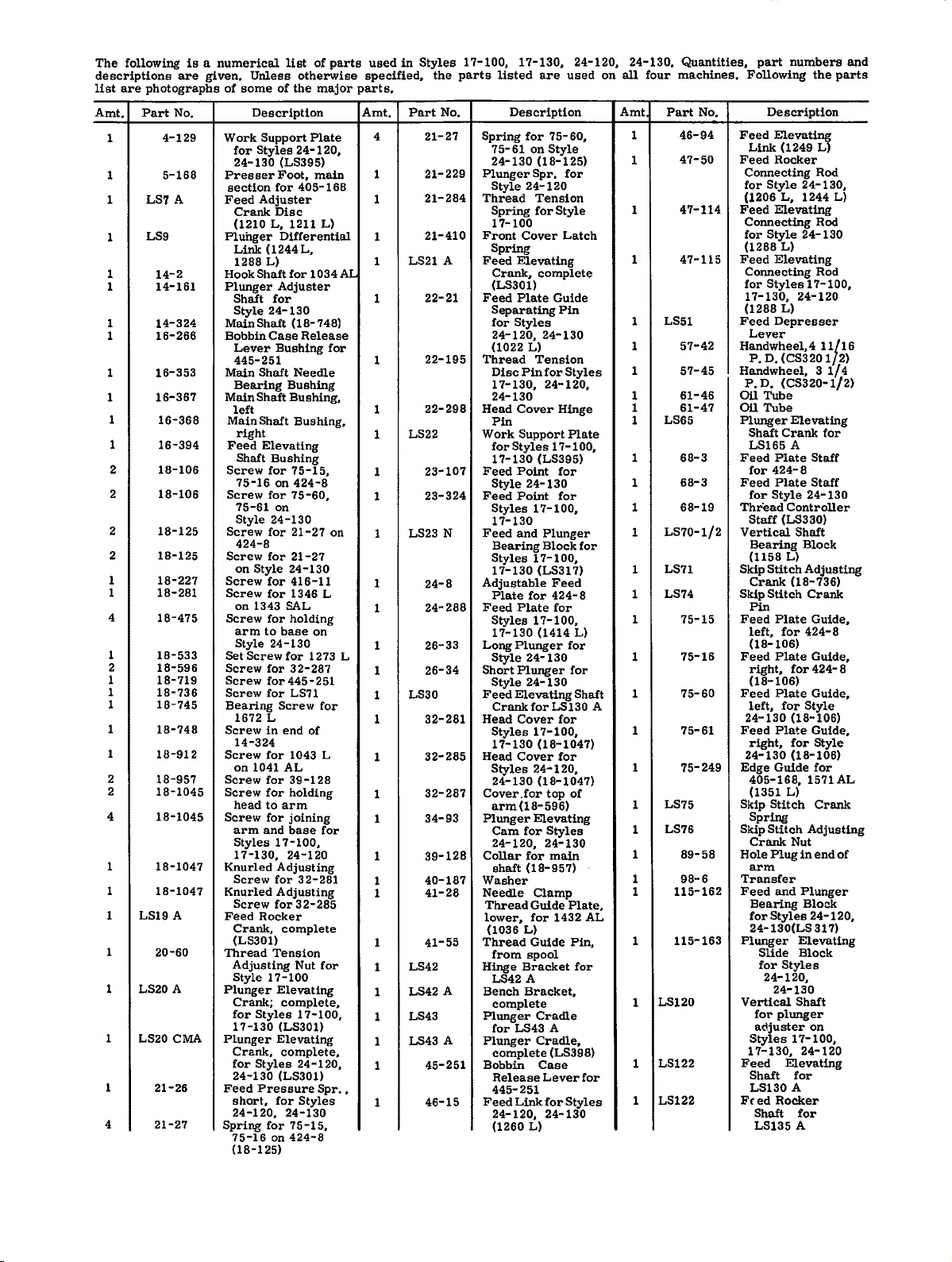
following
descriptions
list
are
photographs
Part
Amt.
1
1
1
LS7
LS9
1
1
1
1
1
1
1
1
1
2
2
2
2
1
1
4
1
2
1
1
1
1
1
2
2
4
1
1
1 LS19 A
1
1 LS20 A
1
LS20 CMA
1
4
is a numerical
are
No.
4-129
5-168
A
14-2
14-161
14-324
16-266
16-353
16-367
16-368
16-394
18-106
18-106
18-125
18-125
18-227
18-281
18-475
18-533
18-596
18-719
18-736
18-745
18-748
18-912
18-957
18-1045
18-1045
18-1047
18-1047
20-60
21-26
21-27
given.
of
Work
for
24-130
Presser
section
Feed
Crank
(1210
Pluhger
Link
1288
Hook
Plunger
Shaft
Style
MainShaft
Bobbin
Lever
445-251
Main
Bearing
Main
left
Main
Feed
Screw
Screw
Screw
Screw
Screw
Screw
Screw
arm
Set
Screw
Screw
Screw
Bearing
Screw
14-324
Screw
on
Screw
Screw
head
Screw
arm
Styles
17-130,
Knurled
Screw
Knurled
Screw
Feed
Crank,
(LS301)
Thread
Adjusting
Style
Plunger
Crank;
for
17-130
Plunger
Crank,
for
24-130
Feed
short,
24-120.
Spring
75-16
(18-125)
Unless
some
Description
Support
Styles
for
Adjuster
Disc
L,
(1244
L)
Shaft
for
24-130
Case
Bushing
Shaft
Shaft
Shaft
right
Elevating
Shaft
Bushing
for
75-16
on
for
75-61
on
Style
24-130
for
424-8
for
on
Style
for
for
on
1343 SAL
for
to
Style
24-130
Screw
for
for
for
1672 L
in
for
1041
for
for
to
for
and
17-100,
for
for
Rocker
Tension
17-100
Styles
Styles
Pressure
for
for
on
list
of
otherwise
of
the
major
Plate
24-120,
(LS395)
Foot,
main
405-168
1211
L)
Differential
L,
for
1034
Adjuster
(18-748)
Release
for
Needle
Bushing
Bushing,
Bushing,
75-15,
424-8
75-60,
21-27
21-27
24-130
416-11
1346 L
holding
base
on
for
1273 L
32-287
445-251
LS71
Screw
for
end
of
1043 L
AL
39-128
holding
arm
joining
base
for
24-120
Adjusting
32-281
Adjusting
32-285
complete
Nut
for
Elevating
complete,
17-100,
(LS301)
Elevating
complete,
24-120,
(LS301)
Spr
Styles
24-130
75-15,
424-8
parts
AL
on
••
used
specified,
parts.
Amt.
4
1
1
1
1
1
1
1
1
1
1
1
1
1
1
1
1
1
1
1
1
1
1
1
1
1
1
1
1
1
1
in
Styles
Part
21-27
21-229
21-284
21-410
LS21 A
22-21
22-195
22-298
LS22
23-107
23-324
LS23 N
24-8
24-288
26-33
26-34
LS30
32-281
32-285
32-287
34-93
39-128
40-187
41-28
41-55
LS42
LS42 A
LS43
LS43 A
45-251
46-15
the
No.
17-100,
parts
listed
Description
Spring
75-61
24-130
Plunger
Style
Thread
Spring
17-100
Front
Spring
Feed
Crank6 complete
(LS301)
Feed
Separating
for
Styles
24-120,
(1022 L)
Thread
Disc
17-130,
24-130
Head
Pin
Work
Styles
for
17-130
Feed
Style
Feed
Styles
17-130
Feed
Bearing
Styles
17-130
Adjustable
Plate
Feed
Styles
17-130
Long
Plunger
Style
Short
Style
Feed
Elevating
CrankforLS130
Head
Styles
17-130
Head
Styles
24-130
Cover
arm(18-596)
Plunger
Cam
24-120,
Collar
shaft
Washer
Needle
Thread
lower,
(1036
Thread
from
Hinge
LS42 A
Bench
complete
Plunger
for
LS43 A
Plunger
complete
Bobbin
Release
445-251
Feed
Link
24-120,
(1260
17-130,
are
for
75-60,
on
Style
(18-125)
Spr.
24-120
Tension
for
Style
Cover
Elevating
Plate
Guide
Pin
24-130
Tension
Pin
for
24-120,
Cover
Hinge
Support
17-100,
(LS395)
Point
for
24-130
Point
for
17-100,
and
Plunger
Block
17-100,
(LS317)
Feed
for
424-
Plate
for
17-100,
(1414 L)
24-130
Plunger
24-130
Cover
for
17-100,
(18-1047)
Cover
for
24-120,
(18-1047)
.for
top
Elevating
for
Styles
24-130
for
main
(18-957)
Clamp
Guide
for
1432
L)
Guide
spool
Bracket
Bracket,
Cradle
Cradle,
(LS398)
Case
Lever
for
24-130
L)
24-120,
used
for
Latch
Styles
Plate
for
8
for
for
Shaft
of
Plate,
AL
Pin,
for
for
Styles
on
A
24-130.
all
four
Amt
1
1
1
1
1 LS51
1
1
1
1
1 LS65
1
1
1
1
1
1
1
1
1
1
1
1
1
1
1
1
1
LS120
1
LS122
1
LS122
1
Quantities,
machines.
Part
No.
46-94
47-50
47-114
47-115
57-42
57-45
61-46
61-47
68-3
68-3
68-19
LS70-1/2
LS71
LS74
75-15
75-16
75-60
75-61
75-249
LS75
LS76
89-58
98-6
115-162
115-163
part
numbers
Following
Feed
Link
Feed
Connecting
for
(1206
Feed
Connecting
for
(1288
Feed
Connecting
for
17-130,
(1288 L)
Feed
Lever
Handwheel,4
P.
D.
Handwheel, 3 1/4
P.
D.
Oil
Tube
Oil
Tube
Plunger
Shaft
LS165 A
Feed
for
Feed
for
Thread
Staff
Vertical
Bearing
(1158
Skip
Crank
Skip
Pin
Feed
left,
(18-106)
Feed
right,
(18-106)
Feed
left,
24-130
Feed
right,
24-130
Edge
405-168,
(1351 L)
Skip
Spring
Skip
Crank
Hole
arm
Transfer
Feed
Bearing
for
24-130(LS
Plunger
Slide
for
24-120,
Vertical
for
adjuster
Styles
17-130,
Feed
Shaft
LS130
Feed
Shaft
LS135
the
Description
Elevating
(1249
L)
Rocker
Style
Style
Styles
Stitch
Stitch
Stitch
Rod
24-130,
L,
1244
Elevating
Rod
24-130
L)
Elevating
Rod
17-100,
24-120
Depresser
(CS320 1 2)
(CS320-1/2)
Elevating
Crank
Plate
Staff
424-8
Plate
Staff
Style
24-130
Controller
(LS330)
Shaft
Block
L)
Adjusting
(18-736)
Crank
Plate
Guide,
for
424-8
Plate
Guide,
for
424-8
Plate
Guide,
for
Style
(18-106)
Plate
Guide,
for
Style
(18-106)
Guide
for
1571
Stitch
Crank
Adjusting
Nut
Plug
in
end
and
Plunger
Block
Styles
24-120,
31
Elevating
Block
Styles
24-130
Shaft
plunger
on
17-100,
24-120
Elevating
for
A
Rocker
for
A
11/16
for
parts
L)
7)
and
AL
of
 Loading...