

Page 1
LEWIS
ARTS and INSTRUCTIONS
F'OR
7 &
24
INVISIBLE
CLASS MACHINES
Models
17-10 24-12
STITCH
MACHINE
MAIN
121-
131
NEW
West
YORK
OFFICE
22nd
11,
N.
COMPANY
Street
V.,
U.
8.
A.
PRINTED
IN
U. &. A.
Page 2
iNDEX
Page
Adjusting
Automatic
Basting
Bight,
Bobbin, how
Bobbin
Bobbin
Breaking
Catalogue, how
Feed Plate Pressure,
Feed Poi
Foreign
and
Groups,
Gr
oups,
Ha
nd
Hook,
Hook,
Inserting
Instructions
Instructions
Models,
Model 24-1
Model 17-
Needles •.•......
Numerical List
Oiling and Cleaning
Ordering
Parts,
P
enetrat
Plunger
Plunger,
Plunger,
Presser
Sack
Setting
Skipping
Speed
Stitch
Straight Felli
Tensions,
Thread
Thread
Instructions
Tension
Work,
how
to
adjust
to
Case,
how
Case Rel
Thread,
nt,
raising
Shipments,
parts
of
Key
to.
list
of
Wheel
....
how
to
raising
Coats
of
Length.
repl
and
and
Removing
for
for
General
2,
Operating.
10,
Operating
Parts
Numerical
ion,
how
Barrel,
how
to
how
to
Fciot, removing
and
Up
of
Machine ....•..
Stitches, how
Machine
how
ng
how
to adjust .••••...
To
Use •.•.
Breakage,
Model 24-1
insert.
to
ease
how
to use
oil
.
..
.
.
ace
lowering ...
Adjusting ....
Ordering
Description
of
Parts.
......
List
to adjust
how
raise
remove
Overcoats
.....•.
to
Stitch,
how
...
Release
width ...
• . . . .
replace.
.•....
to
overcome
••••....
how
and
lowering
how
to
and
time.
Work
.
. • .
. . .
.
..
to
remove.
and
. . .
and
. .•..•.
to
ove
adjust ...
how
....
to
overcome
• .
..
2.
to
adjust
mount
Parts.
lower
••••
replacing
rcome
..
to
•••
. . .
head,
.
.
•
..
••
..
produce
.•.
5
to
27
24
22
12
'J
13,
14
.
..
.
and
c l
ean
hook
25,
16
26
5
13
21
6
3, 4
2
6
14,
15
15 ,
16
9.
10
5
to
2 7
5
5,
6
21
to
23
19
7,
8
72
to
75
6, 7
5, 6
72
to
75
22
18
19,
20
17,
18
13
20,21,23
6
26
.
7
10
19
12
8,
9
25,
26
Page 3
2.
INDEX
Page
3
Thread
Threading
Timing
Two
Unp
Wid
Main
He
Hook
Hook
Needle
Take-Up Lever •••
Thr
Skip
Cover .....
Feed,
Feed,
Feed
Feed
Plunger
Plungers
Knee
Work
Miscellaneous
Presser
Presser
Pre
Presser
Controller
Needle
to
One
acking
th
of
Shaft
ad
Shaft ...•
Drive
...
Drive
ead
Tension ..•
Stitch
Feed
Feed
Elevating
Driving •..
Press
Support
sser
guide,
m
aterials,
• . •
••.
with
Stitch. • •..•..
Machine •...•.•
Bight,
how
..••
.••
• .
•••
•.•
Plunger
•...
Plate
Plate and
...••....
Cradle
and
.. ..
.•..
••••..
Plate.
. . . • • ••.•. .•.
Fo
ot,
Model
Foot
for
Feet
for
Model
17-10 •..••....
Feet
for
Model
Spring .•.
•.•••..
Plunger
to
adjust
LIST
Group
.
.
•..
and
Plunger, Model
Plunger,
.•.•.....
Adjusting.
2.4-12. •.. . • . .
piped
edges,
piped
edges, with
silks,
rayons
17-10
.......
.
OF
GROUPS
Model 24-12.
..•
.
.•.••..•.•
Model 17-1
plow
•.•••.•.•
and knit
.•
17-10
....
edge
•••••
0.
16
9
17
19,
2.0
6
12.
(f)
(L
:)
0
0::
P
age
2.8
30
32.
34
36
38
40
42.
44
46
•.
48
50
52.
54
56
58
60
62.
64
66
68
.
70
Plate
2.
3
4
5
6
7
8
9
10
11
12.
13
14
15
16
17
18
19
2.0
2.1
2.2.
<.9
w
(f)
<!
co
ell
::2!
0::
<!
C\J
I
o;;t
C\J
Q
z
..
0
I
t::
(f)
_J
w
Cl
0
::2!
Page 4
5
TAKE
MODEL 17-
-UP
LEV
VER
ER
H
OOK
GRO
GROUP
CO
GROUP
UP
10
HEAD
THRE
___.>---
GROUPS
AD TENSION
GRO
UP
INSTRUCTIONS
LEWIS
1.
2.
needed,
the
column
near
serial
near
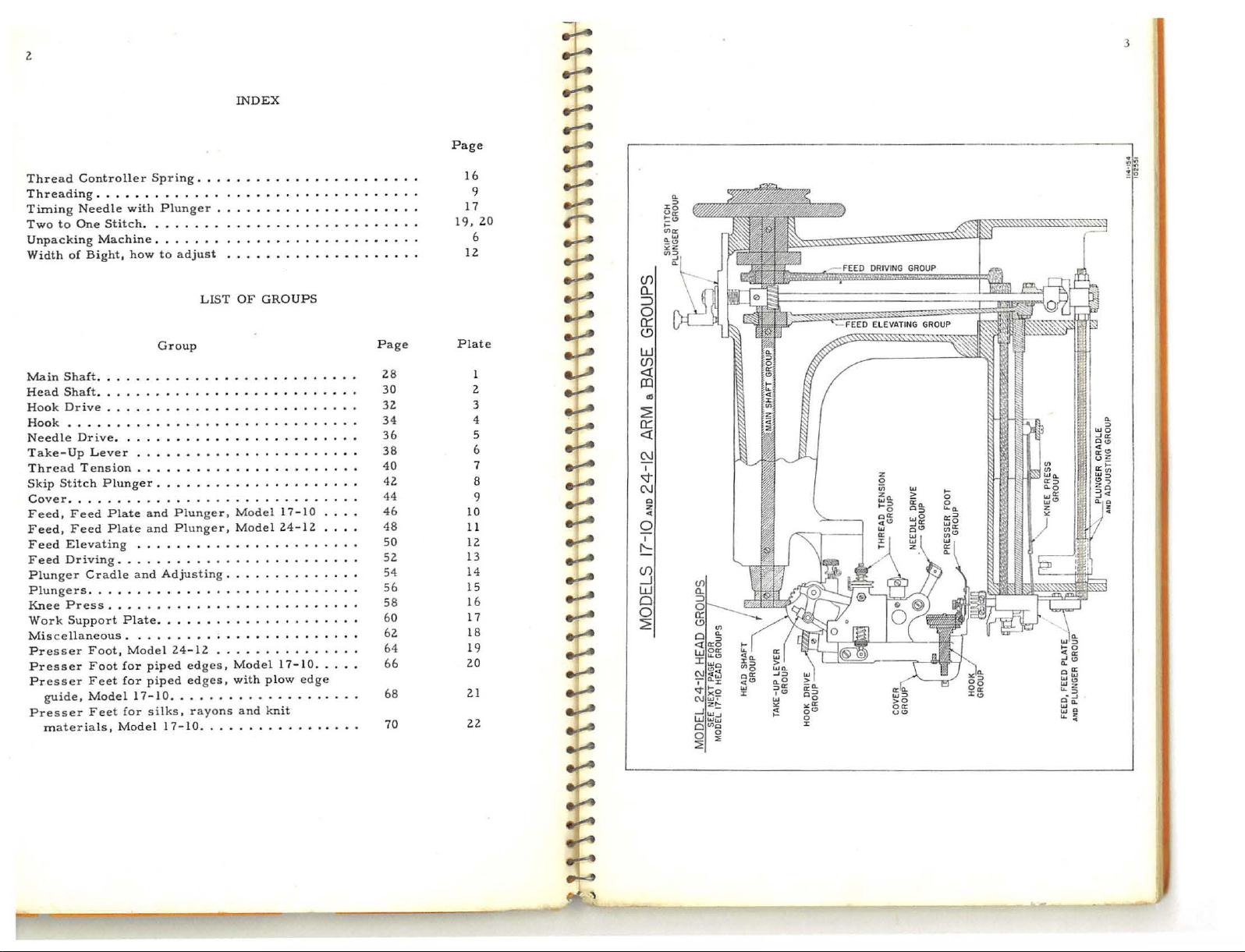
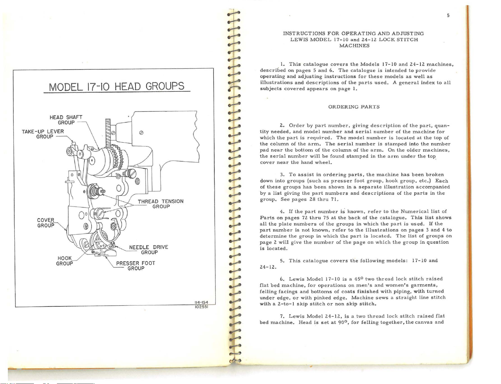
3.
into
list
4 .
on
plate
numb
5.
covered
part
t he
groups
giving
pages
.
This
on pages 5 and
and
Order
and
of
bottom
number
the
To
groups
pages
If
t
he
numbers
er
is
the
give
This
described
operating
illustrations and
subjects
tity
which
t
he
pad
the
cover
down
of
these
by
a
group. See
Parts
all the
pa
rt
determine
page 2 will
is
located
24-12.
MODEL 17-
catalogue
adjust
ing
descriptions
appears
by
part
model
is required.
the
arm. The
of
will
hand
wheel.
assist
in
(such
has
been
the
part
28
thru
part
num
72
thru
not
known,
group
in
the
number
catalogue
FOR
covers
6.
instructions
on
ORDERING
number,
numb
the
column of
be
found
ordering
as
presser
shown
numbers
71.
ber
75
at
of
the
refer
which
covers
OPERATING
10
and 24-1
MACHINES
the
The
catalogue
of
the
page
I.
giving
er
and
model
serial
stamped
parts,
in a separate
and
is
known, refer
the
back
to
the
part
the
page
the
serial
number
foot
in
t he
The
groups
of
AND
2 L
Models 17-
for
parts used
is inte
these
PARTS
description
number
number
is
the
arm.
in
the
the
machine
group,
descriptions
of
the
catalogue
which
the
illustrations
is
located. The
on
which
following
ADJUSTING
OCK
STITCH
10
and 24- 12
nded
models
. A
general index
of
is
located
stamped
On
the
arm
under
has
hook
group,
illustration
of
to
the
Numerical
part
on
the
models:
machines
to
provide
as
well
as
of
the part,
the
machine
into the number
older
been
the
parts
. This
is
used.
pages 3 and 4 to
list
gro
up
I 7- 10
quan
at
the
top
machines,
the
top_
broken
etc.)
Each
accompanied
in
list
list
If
the
of
groups
in
question
and
to
all
for
of
the
of
shows
,
-
on
114·154
1
0255
1
6.
Lewis
fl
a t
bed
felling facings
under
wit
bed
machine,
edge,
h a 2-to- 1
Lewis Model
7.
machine.
or
and
with
skip
Head
Mode
for
bottoms
pinked
stitch
is
l 17-10
operatio
of
edge. Machine
or
non
24-12,
set
at
is a 45°
ns
on
coats
skip
is a two
90°,
two
men's
and
finished with
stitch
.
thread
for
felling
thread
sews a straight
lock
women
piping,
lock
together,
' s
stitch
the
stitch
garments,
with
line
raised
canva
raised
t u
rned
stitch
s and
flat
Page 5
6
cloth
at
Sometimes
remove
Use
by
lifter
ot
carefully
that
Lift
take-up and
machine.
parts
before
by
at
the
hook
shipping
head
order.
red
frame
say
m
of
service
properly
the
8.
the
a n
ail
nails
or
and
her
small
you
will
the mac
9.
are
the
loosening
its
lowest
hook
and
freely.
machines
mechanism
To
paint,
of
the
1
0.
in a clockwise
ach
ine.
11.
first
importance.
and
edge
referred
To
remove
nails and
puller
screws
bobbin
parts
through
find
hine
tension
To
protect
covered
machine
thumb
point.
bobbin
Also
aid
showing
machine
The
Proper
satisfaction
oil
ed
of
sack
to
UNPACKING
the·
screws
to
avoid
driven throu
winder
will
be
the
material
all
the
out
of
studs
the
with
is
put
screw.
Use
case,
wipe
to
distant
and
pack
reassembly,
the
relative
and
hand
wheel
direction
OILING
lubrication
Lewis
and
cleaned.
coats
as a bluff
the
vaseline,
and
AND
machine
that
breaking
gh
are
attached
found
wrapped
used
parts
and
box
very
as
these
machine from
in
operation. Take
To
remove
gaso
line
so
as
needle
countries,
separately,
the
also
the
HAND
turns
when
Invisible
if
reasonable
The
to
castings
position
AND
and
foot,
overcoats
edge
.
SETTING
from
hold
the
the
machine.
the
outsi
to
the side
for pack
equ
ipment
carefully
parts
which
rusting
must
this
or
petrol
allow
and
other
it
so
of
timing
WHEEL
away from
seen
from
CLEANING
thorough
Stitch
care
machine
finished
UP
the
box,
take
brace
blocks
These
de
of
the
ing
that
to
be
off
cover
to
remove
is
necessary
to
gears
the
of
the
the
the
cleaning
Machines
is
should
exposed
insure
head
taken
of
b e
fore destroying
goes
avoid break
beyond
while
carefu
aluminum
the
ead
gears.
operator, that
hand
be
in a package.
project
the thr
as
and
with
a pl
off
the
in
position.
blocks are helrl.
box.
The
the
box,
and
Be
sure
with
the
the
head
in
transit,
lly
wiped
head
take-up
the
grease
to
pass
over
parts.
to
remove
delivery
are
marked
mechanism
wheel
of
the machine
will
give
in
keeping
oiled
and
ain
cover
knee
ing
must
When
end
clean
edge,
and
the
to
look
it,
machine.
the
of
the
all
off
cover
be
from
the
the
in
good
with
on
the
is
to
of
the
years
them
ed
so
is
of
::t:
-.!..-
...:...-
~
......
......
~
.-r-
--1
.-r-
--r
~
~
~
~
~
..;...e
.;:...e
~
~
..;;...e
~
rr--
.,:.r-e
r.:--
daily
as
lint
function
head
and
turning
ings,
gears,
these
drop
of
hours. The
to
the
than
ten
necessary
mechanism
the
presser
work
plate,
require
turning
base,
the
plate
every day
points
minute. A speed
in starting a
stitches
in
all
improperly.
ll.
In
wipe
the
hand
small
parts
oil
in
right
of
drops
13.
Besides
to
will
foot. This
or
14.
On
oiling
back
all
of
which
15.
It
near
16.
See that
to
will
cause
17.
Lewis
18.
Lewis
per
19.
Needles
necessary
and
off
etc.
back
hook
lubricate
the
is
avoid lint
new machine
minute.
dirt
accumulates
cleaning
the
parts
wheel
and
oil
daily.
of
the
shaft
the
hook. A drop
that
do
thoroughly
be
found
by
tur
nin
all
types
near
the
machine,
require
also
necessary
the
hand
the
the
machine
Model
of
900
Modell4-ll
for
s i
zes
in
the
moving
the
machine
with a clean
you
will
holes
On a
bobbin
should
not
reach
the
plunger
in
the
mechanism
g the
of
machines there
base,
several
daily
wheel
feed
points
accumulating. Accumulation
17-10
to
o
llOO
or
Lewis
with
either a taper
always remove
see
the
. A
few
new machine
case
oiled
of
oil
the
parts
oili
n g
and
bed
of
may
movable
lubrication
to
oil
Figure
{Figure
feed
SPEED
can
be
stitches
can
be
Invisible
race-way
the
0,
improperly.
be
machine
immediately
to
with a new
NEEDLES
cloth.
various
drops
through
well
feed
the
back
the
operated
operated from
of
it
placed
requ
head
mechanism.
machine
be
uncovered
on
are
below
parts
.
machine
Page
P)
per
operator
Stitch
point
Do
is
iring it.
the hin
lO.
minute
Machines
parts,
causing
the
cover
not
use
moving
oil
every
the
mechanism
movable
Page
up
or a ball
parts, bear-
should
necessary to
two
hole
in
will
do
imm
ediately
by
ges.
the
hand
will
be
at the
ll
are
of
lint
to
1500
is recomme
.
90
them
from
waste. By
be
placed
place
or
three
the
casting
more
good
it
is
also
The
feed
removing
parts
that
wheel.
found
in
top
underneath
cleaned
in
the
stitches
t·
to
1100
are
furnished
eye. Taper
7
to
the
on
a
be\ow
the
By
the
feed
per
nded
~
----
Page 6
8
point needles are recommended
difficult
m
to
si
is
fir
the
needle for
the bla
of
needl
a l
what
the
the needle.
in
ri
genuine
and
t o
ateria
ls and
hug
or
ble
required
s t
average
arger nee
ghted word
ride
to
form a good loop,
20.
importan
size of
de
of
2
1. A number
e ,
such
needle
thread
22. Needles
the
following
23 .
Lew
the
cor
penetr.ate. Ball Eye need
soft
finish
ed
with
the
.
The
selection
ce. The l
the
needle,
Lewis Class
the
needle is .035"
weight. For
as a number
dle, su
ch
is sel
ected,
or
yarn
that
for
sizes:
Taper Point
Not
Scarfed
29-123
29-123-1/2
29-124
29-124-l/2
Use
ONLY genuine LEWIS Needl
"LEWIS" stam
is
Invisible
rect
size
materials.
needles
it
of the pro
ast whole
thus
29 -
17
and
3-l/2
lighter than
3.
as a number 4 or a number 4-1/2.
be
sure
is
to
L ewis
Stitch
stamped
for
light materials and materials
les are
If
on
its
is a good
figure
133-1/2
24
Machines.
in
diamet
needle
For heavier than
that the
be used
17-l 0 and 24-1
ped
on
Machine
on
each sha
T
HREAD
the mate
return
indication
per size and
(and fract
is a numb
er.
will
be found
average
eye
to
run
the
shank
needles
nk.
recommended
rial
strok
e , making it
that a Ball Eye
kind
of n
ion
if
er
3-1/2 Ball
Th
e 3-1/2
satisfactory
material,
average
is large
freely through
2 m
Ba
ll
Not
2929
-13
29
- 133-l
29-134
29-134-1/2
es. Look
of
enough to
achines
Eye
Scarfed
132-l/2
3
/2
each needle. All
have
the
for
heavier
has a tendency
use a smaller
materia
for
impos-
needle
eed
le
is
indicated)
indicat
Eye
ed
for
l, use
No matter
permit
the
eye
are
furnishe
the
copy
name Lewis
of
that
work
of
is
-
9
25
r-t
__,....
"00
"
or
Chart
threading,
the
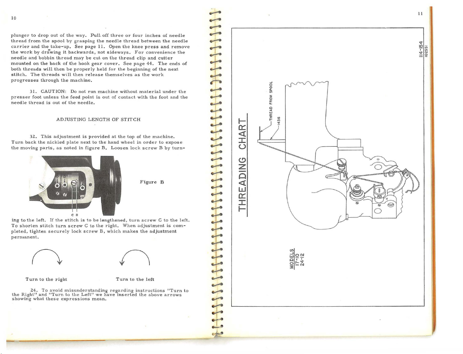
26.
on
threading
. SILK:
"00
For
page 11.
we
Use
0"
in
threading
recommend that
.
eithe
the
bobbin
THREADING
Until
thoroughly
r
"0"
.
Models
the
or
"00"
in
the need
MACHINE
17-10 and 24- 12,
familiar
take-up
with
be
at
its highest poi
le
and
see Thre
the process
either
ading
of
nt
during
._...
....-....
._..
........
........
.......
the bobb
bobbin
27. Turn hand wheel
in
case.
Open
.
-.,......
8.
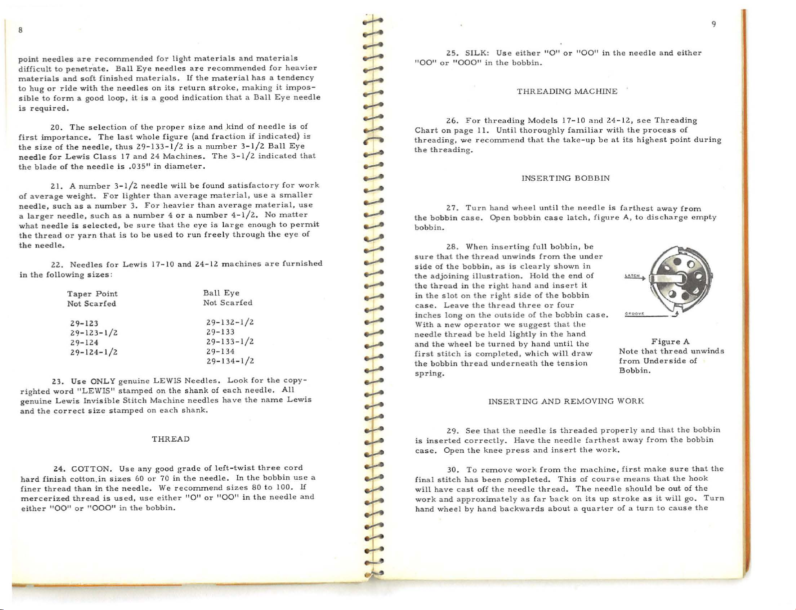
When inserting
2
su
r e
~
d
.,_;.A
~
~
........
........
.,_A
~
--]
...:--
-+-
~
~
that the thread
side
of
the adj
the
in
case
i
Wi
needle
and the
first
the
spring
the
oining
thread
the slot
. L
nches long
th a new
thread
stitch
bobbin
.
bobbin,
illus
in
the right
on
the right
eave
the
on
the
operator
be
wheel
be
is
completed, which
thread
t r
thread
held
turned
underneath
I
NSERTING
INSERTING BOBBIN
until
bobb
in
case
full
unwinds
as
is
ation. Hold
outside
we
lightly
from
clearly
hand
a nd
side
of
three
or
of
the
suggest that
in
by hand
the tens
AND
the needle is
latch, figure
bobbin,
the
shown
the
end
insert it
the
bobbin
four
bobbin
the
the
hand
until the
will
draw
ion
REMOVING
be
under
in
of
case
.
farthest
A,
to
discharge
Note
that thread unw
om
Und
fr
Bobbin.
WORK
away from
gu
r e A
F i
erside
empty
of
ind
s
:t:
29.
See
that
the
is
inserted
case.
correctly. Have the
Open
the
knee
needle
press
and
is
threaded
needle
insert the
properly
farthest away
work.
and
from
that
the
the
bobbin
bobb
in
ha
rd
finish cotton.in
finer
thread
merceri
either
"00"
24. COTTON. Use any
than
zed threa
or
in
the
d is
"000"
sizes
needle. We
used, use eithe
in
the
60
good
or
70
bobbin.
gra
de
in
of l
the need
recommend
r
"0"
or
eft-twi
le .
sizes
"00"
In
st
the
in
three cord
bobbin
80
to 100.
the
needle
use
a
If
and
final stitch
will
work
hand
30.
have
and
wheel
To
remove
has
been
cast
off
by
hand
the
backwards
approximately
work from
s:ompleted. This
needle thr
as
the
ead. The
far
back
about a quarter
machine,
of
on
its
course
needle
up
first
means
should
stroke
of a tu
make
that
be
out
a s
it
will
r n
to cause the
sur
the
e t
hook
of
go.
hat
the
the
Turn
Page 7
10
plunger
thread
carrier
the work
needle
mounted
b
stitch. The
progresses
presser foot unl
needle
Turn back
the
ing
To
pleted,
perntanent
the
showing what
oth
moving
to
shorten
to
from
and
and
threads
31.
thread
32.
the
tighten
Turn
24. To
Right"
drop
the
the
by
drawing
bobbin
on
the back
will
thr
through
CAUTION: Do
This adjustment
the
parts,
left.
stitch
.
to
and "Turn to
out
spool
take-up.
thread may
then
eads
ess
is
out
ADJUSTING
nickled
as
lf
the
turn
securely
the
right
avoid
these
of
the
way. Pull. off
by
grasping
See
it
of
be
will
the mac
the
of
plate
noted
misunderstanding
expressions
page
b a
ckwards,
be
the
hook
properly
then
release
hine.
not
feed
point
the
needle.
is
next
in
figure
is
lock
the
to
screw
Left" we
screw C to
the
needle
11.
Open
not
sidew
cut
on
gear
cover. See
held
for
themselves
run
machine
is
out
LENGTH
provided
to
the
hand wheel
B . L
be
lengthened, turn
the
right. When
B ,
which
have
mean.
three
or
four
thread
the knee
ays. For
the
thread
the
beginning
without
of
contact
OF
STITCH
at the
lop
oosen
makes
Turn
regarding instructions
inserted
inches
between
press
conven
clip and
page 44. T h e
lock
to
of
as
the
work
material
with
the
of
the
machine
in
order
screw B by
F i
gu
r e B
screw C to
adjustment
the adjustment
the left
the
above
of
th e
and
ien
cutter
the
under
foot
to
expose
arrows
needle
needle
remove
ce
the
ends
n e
xt
the
and
.
turn
the
is com-
"Turn
of
the
-
left.
to
~
~
....:---
~
~
--r
--1
~
:t:
....
--1
--1
--r
.,...
~
&.!-A
J...
~
._!...
..J....
.J.-.
+
~
:t:
.,:..e
~
.,:..e
~
~
~
.,:;.-e
:c
..,:.....
.,_.
.......
.......
t-
cr:
<(
::r:
u
(.!)
z
-
Q
<(
w
cr:
::r:
t-
...I
0
0
Q.
(/)
:l;
0
0::
lL
c
~
lLI
0::
J:
....
en
~Q~
Q I I
o
r-<t
::E
-N
II
<t
10-
_.,
I
<t"'
=~
<ll
I
tl
Page 8
12.
....;...
13
the
not,
tight,
the
draw
rades
machine
depth
guide
the
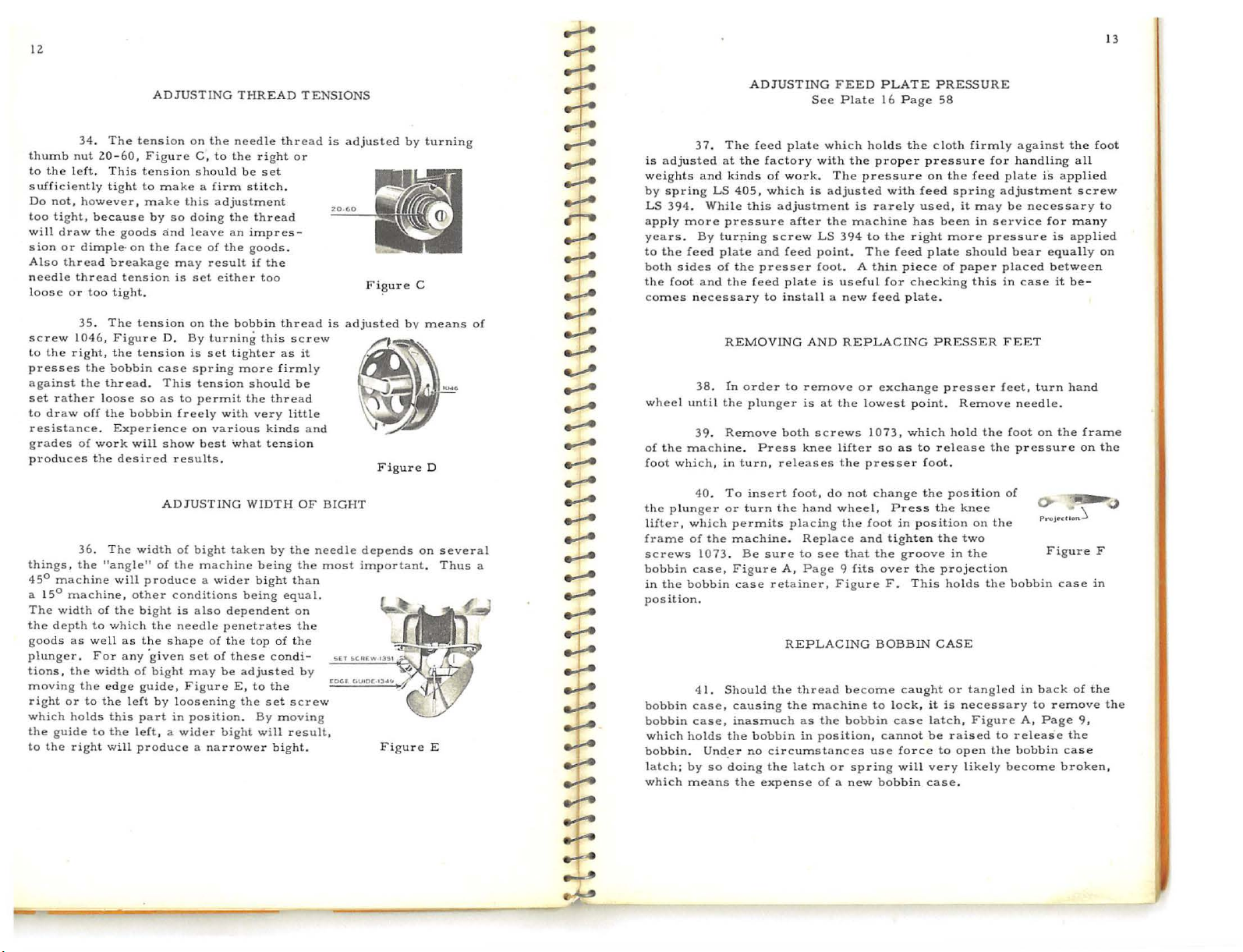
34. The
nut
left.
however,
because
draw
or
dimple· on
thread
thread
or
too tight
35. The
right, the
the
the
off
a nce.
of
the
36. The
achi
width
to
as
well
the
or
to
holds
to
right
2.0-60,
the
loose
work
of
width
the
thumb
to
sufficiently
Do
too
will
sion
Also
needle
loose
screw 1046,
to
presses
against
set rather
to
resist
g
produces
things, the
45°
a 15° m
The
the
goods
plunger. For
tions, the
moving
right
which
the
to
ADJUSTING
tension
Figure
This
tension
tight
to
make a firm
make
by
goods
breakage
tension
Figur
bobbin
thread. This
the
Experience
desired
"angle"
will
ne,
the
which
as
any 'given
edge
this
the
will
so
and
the
face
may result
is
.
tension
e D.
tension
case
so
as
bobbin
will
show
results
ADJU
width
of
the
produce a wider
other conditions
bight
the
the
shape
of
bight may
guide,
left
by loo
part
in
left, a wider
produce a narrower
on
C ,
sho
this
doing
leave
set
on
By
is
spring
tension
to
permit
freely
on
best
STING
of
bight
machine
is
also
needle
set
Figure
sening
position.
THREAD
the
needle
to
the
uld
be
stitch
adjustment
the
an
impres-
of
the
goods
either
the
bobbin
turning
set
tighter
more
should
the
with
various
'what
.
WIDTH
taken
being
dependent
penetrates
of
the top
of
these
be
adjusted
E,
the
bight
right
set
thread
if
the
too
this
thread
very
kinds
tension
by
being
bight
condi
to
the
set
By
will
bight.
TENSIONS
thread
or
.
.
thread
screw
as
it
firmly
be
little
and
OF BIGHT
the
the
than
equal.
on
the
of
the
-
by
screw
moving
result,
is
20
is
needle
most
adjusted
GO
adjusted
FigureD
depends
important.
Figure
~
by
by
turning
means
on
several
Thus
E
of
~
~
is adjust
weights
by
LS
~
...;-e
...;.-e
..,:..e
~
apply
years.
to
both
the
comes
37.
ed
and kin
spring
394. While
more
By
the
feed
sides
foot
and
necessary
::c
..,::..-
ADJUSTING
The
feed
at
the
ds
LS
405, which
this
pressure
turping
plate
and
of
the
presser fool
the
feed
REMOVING
plate
factory
of
work. The
adjustment
after
screw
feed
plate
to
inst
FEED
See
Plate
which
with
the
is
adjusted
is
the
machine
LS
394
point. The
. A
is
useful
all a new
AND
REPLACING
PLATE
16
holds
proper
pressure
with
rarely
to
the
feed
thin
for
feed
PRESSU
Page 58
the
c l
oth
pressure for
on
the feed
feed
used,
has
been
right
more
plate
piece
of
chec
king
plate.
PRESSER
firmly
spring
it may
in ser
should
paper
this
RE
against the
handling
plate
is
adjustment
be necessa
vice
for
pressure
placed
in
FEET
is
bear equally on
between
case
it be-
all
applied
screw
r y
many
applied
foot
to
~
38. rn
order
to
........
wheel
until
the
~
__..
__..
.....-...
~
~
...;...e
.,;..e
a
.,.;...e
.,_.A
__..
....,....
of
foot
the
lif
frame
screws
bobbin
in
position
39.
the mach
which,
40.
plung
ter, which
of
1073.
case, Fig
the
bobbin
.
plunger
Remove
ine.
in
turn,
To
insert
er
or
turn
permits placing
the
machine.
Be
ure
case
::t:
._;;..e
+-
.,:...e
:t:
...;.-e
~
~
~
~
~
~
bobbin
bobbin
which
bobbin. Under
latch;
whi
41.
case, causing
case,
holds
by
so
ch
means
Should
inasmuch
the
bobbin
no
doing the
the
remove
is
both
Press
knee
releases
foo
the
hand
Repl
sure
to
A ,
Page 9 fits
retainer
REPLACING
the
thread
the mach
as
in
circumstances
latch
expense
at
the
screws
lifter
the
t,
do
not
wheel,
the
ace
see
that
, F
igure
become
ine
the
bobbin
position,
or
of a new
or
exchange
lowest point. Remove
1073,
so
presser
change
Press
foot
and
tight
the groove
over
F.
BOBBIN
to
lock,
case
cannot
use
spring
bobbin
which
as
to
in
posi
en
the
This
caught
force
will
presser
rele
foot.
the
the
tion
the
projecti
holds the
CASE
or
it
is
latch,
be
to
very
case
hold
position
in
raised
open
.
ase
knee
two
necessary to
likely
feet, turn hand
needle.
the
foot
the
pressure
of
on
the
the
on
bobbin
tangled
Figure
to
release
the
bobbin
become
in
A,
on
Figure
back
remove
Page
the
case
the
case
broke
frame
on
of
9,
the
F
in
the
the
n,
Page 9
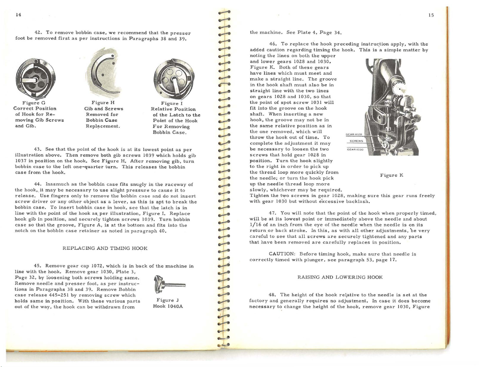
14
f
Correct Pos i
of
moving
and
illustration
1
bobbin
case from
the
release. Use
screw
b
line with
hook
case
n
line with
P
Remove
tions
case
holds
out
42..
oot
be
rem
Figu
re
G
Hook
for Re-
Gib
Gib.
43. See that
037
in pos
case
44.
hook
,.
it
driver
obb
in
case. To
the
gib
in
so
that
otch
on
the
45. Remove
age
the
32., by
needle
in Parag
release 445-2.51
same
of
the
way, the
To
remove
oved first
tio
n
Screws
above. Then rem
ition
on
to
the
the
hook.
Inasmu
may
fingers
or
any
point
position,
the
groove, Figu
bobbin
hook. Rem
loosening
and
raphs
in
position. With
bobbin
as
the point
the
hook
left
one
ch
as
be
necess
only
other
insert
bobbin
of
the
and
case
REPLACING
gear
ove
both
presser
38
and
by
hook
can
case, we
per
ins
tructions
Figure
Gib and
Removed
Bobbin Case
Repl~cement.
. S
-qu
the ·bobbin
ary
to
object
hook
secure
retainer
cap
screws
39.
removing
of the
ove
ee
arter
to
remove
case
as.
ly
re
A,
AND
1072.,
gear
foot,
Remove
these
be
withdrawn
Scr
hook
both gib
Figur
turn. This
case
use
as
a l
in
per
tighten
is
as noted
which
1030,
holding
a s
per
screw
various
recommend
in
Paragraphs
H
ew s
for
is
at
screw
e H.
After rem
fits
slight pressu
the bobb
illustration, Figure
at
TIMING
snugly
ever,
as
hook, see
screws
the
bottom
in
is
in
Plate
same.
instruc
Bobbin
which
parts
from
its
lowest p
s 1
039
releases
re
in
case
this
that
1039.
and fits
paragraph
HOOK
back
3,
-
that
Relative
in
to
is
the
of
the
presser
38
and
Fi
gure
the
Latch
of
Removing
oint
ng gib,
the bobb
cause
do
to
latch
I.
Replace
Turn
into
40
.
Figure
Position
the Hook
Case.
as
holds gib
it
not
break
is
bobbin
J
of
Point
For
Bobbin
which
ovi
the raceway
and
apt
the machine
Hook 1040A
39.
to the
per
turn
in
to
insert
in
the
of
the
in
~
.......
~
~
.......
..,:.-e
.,.:...e
~
.,....
.,_;....e
.....-..
~
~
....-...
..,
--r-
..,
..,
--1
..,:..e
..;-.-
~
.-i-4
~
--0
.,;..e
.,;...e
...;-e
..,::A
~
~
~
~
the
machine.
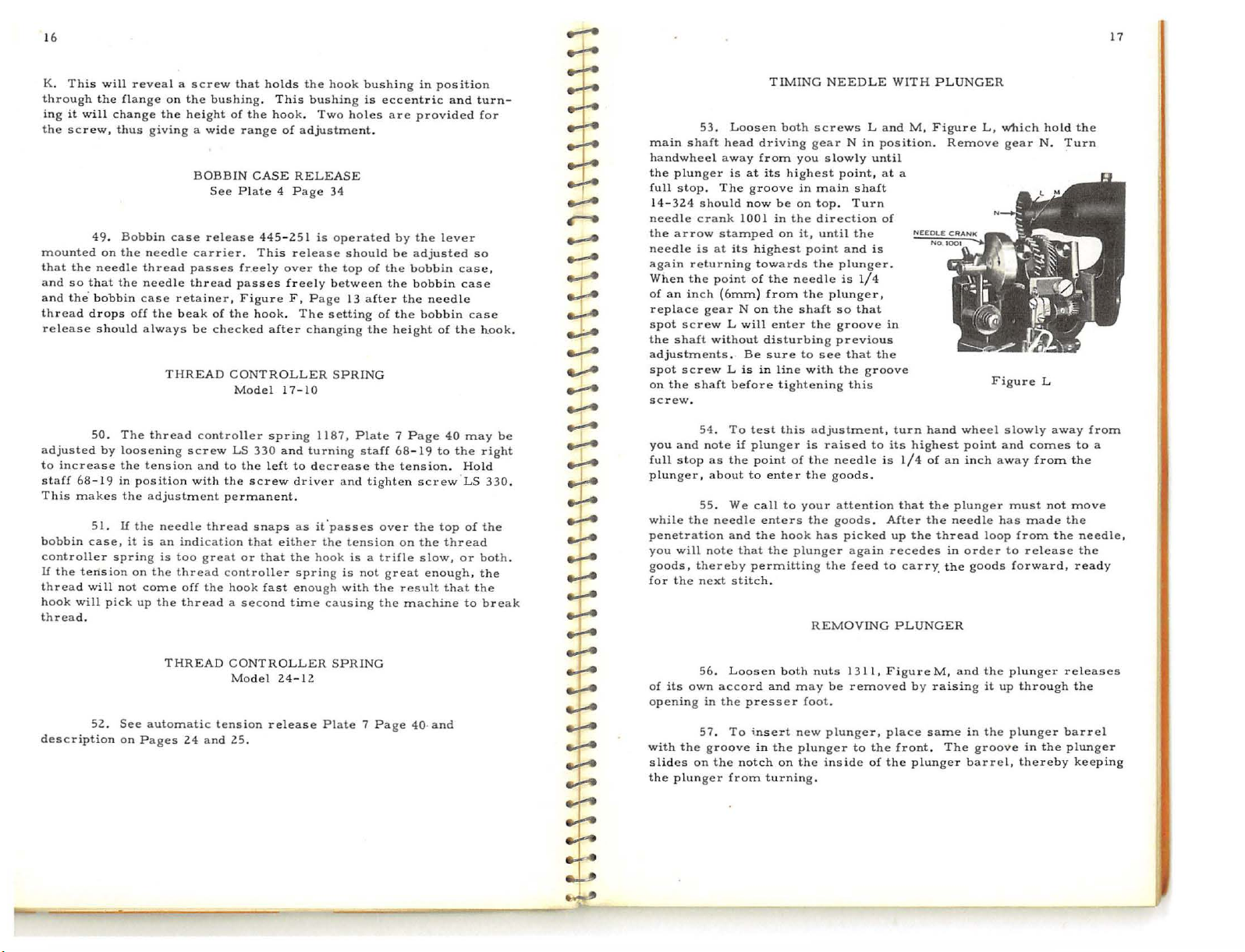
46. To
a
dded caution
noting
the
lin
a
nd
lower
Figure
have
make a strai
in
the
straight
on
gears
the point
fit
into
shaft.
hook,
t
he
the
throw
complete
be neces
screws
position. Turn
to
the right
the thread loop
t
he
up
the
slowly,
Tighten
with
will
1/16
return
careful to
that
correctly
factory
necessary
gears
K.
Both
lines
which
hook
shaft
line
102.8
of
spot
the
groove
When
the groove
same relative
one
removed,
the
hook
the
s a
ry
that
hold
in
needle;
be
have
or turn
needle
whichever
the
gear
t~o
1030
47. You
at
its lowest point
of
an
inch
or
back
see
been removed
CAUTION:
timed with
48.
The
and
generally requires
t~
See
Plate
repla
regarding
es
on
both
102.8 a
of these
must
ght
line. The
must
with
the
and
1030, so
screw
on
inser
ting a new
may
posit
which
out
of
adjustment
to loosen
gear
the
hook
order
more quick
the
thread
may
screws
but
without
will
from the
stroke.
that
all
Before tim
RAISING
hei
ght
change
4,
Page
ce
the
hook
timing
the
upper
nd
1030
gears
meet
and
groove
also
be
two
lines
that
1031
the hook
time.
to
loop
note
plunger,
the
will
not
be
in
ion
as
will
To
it
may
the
two
102.8
in
slightly
pick
up
ly
hook
p i
more
be required
in
gear
excessive
that
or immediately
eye
of
In
this,
screws
are carefully
AND
of
the
height
34.
preceding
the
hook. This
,
in
in
from
ck
.
102.8, m
the
the
as
are
ing
see paragraph
hook
no
of
aking
backlash
point
of the
above
needle
with
all
securely
replaces
hook,
make
LOWERING HOOK
re\ative
adjustment. In
the
hook,
instruc.tion
is a simple
sure
.
hook
when
other adjustments,
tightened
in
sure
53,
to
the
remove
Figure
this
when
the
needle and
the
need
and any
position
that need
page
needle is
case
gear
apply,
gear
properly
le
17 .
it
1030,
matte
K
is
.
set
does
with
runs
on
be
parts
le
the
r by
freely
timed,
about
its
very
is
at
the
become
Figure
15
~
.J_,
~
~~----~
------------~~
=
~~-
~--~------~--------
-
..
·-~~------------------------------------------------~-'
Page 10
16
K.
This
through
ing
it
the
screw,
mounted
that
the
and
so
and
the. bobbin
thread
release
adjusted
to
increase
staff 68This
makes
bobbin
controller
lf
the
tens
thread
hook
will
thread.
will
the
will
change
thus
49.
Bobbin
on
the needle
needle
that
the
drops
should
50.
The
by looseni
the
19
in posi
51. U the
case,
spring
ion
will
not
pick
reveal a screw
flange
on
the
the
height of
giving a wide
BOBBIN
case
thread
needle
case
off
always
tension and
the
it
is
on
come
up
carrier.
passes
thread
retainer,
the
beak
be
THREAD
thread
ng
screw
tion
with the scr
adjustment
needle
an
indication
is
too
the
thread
off the
the
thread a second
that
bushing.
See
release
of
checked
controller spring
thread snaps
great
holds
This
the
hook. Two
range
of
CASE
Plate 4 Pa
445-251
This
freely
over
passes
the
CONTROLLER
Model 17-
LS
to
permanent.
controller
hook fast
Figure
hook.
330
the
that
or
that
freely
F, Page
after
and
left
ew
either
the
time
the
hook
bushing
ge
34
is
the
between
setting
cha
nging
10
1187,
turning
it"passes
the
hook
causing
holes
operated
should
top
13
SPRING
and
tension
is a trifle
is
with
adjustment.
RELEASE
release
The
to decrease
driver
as
spring
enough
bushing
is
of
after
the
Plate 7 Page
staff
tighten
not great
in
eccentric
are
provided
by
the
be
adjusted
the
bobbin
the
bobbin
the
of
the
bobbin
height
68-19
the
tension. Hold
screw
over
the
on
the
slow,
the
result
the
machine
position
and
turn-
for
lever
so
case,
case
needle
case
of
the
hook.
40
may
to
the
right
LS
330.
top
of
the
thread
or
that
to
both
the
break
enough, the
be
...:-e
17
--1
TIMING
53.
~
..4
.J,.
:}
.....-..
r-e
.......
......
.......
.......
.......
~
.,!....
.........
...-..
~
~
~
~
.,..
~
~
..,;-.-
.
.......
-r-
.,;-e
main
handwheel
the
plung
full
stop.
14-
324
needle
the
arrow
needle
again
When
of
an
replace
spot
the
shaft
adjustments.
spot
on
the
screw.
you
and
full
stop
plunger,
while
penetration
you
will
goods,
for
the next
Loosen
shaft head driving
away from
er
is
at
its
The
should
cra
is
returning
the
inch
screw L will
screw L is
shaft
54.
55.
the
thereby
groove
now
nk
1001
stamped
at
its
highest
towards
point
of
(6mrn} from
gear N on
without
note
as
about
needle enters
note
Be
before
To
test
if
plunger
the
to enter
We
and
that
permitting
stitch.
disturbing
in
point
call
the
be
in
on
the
the
enter
sure
line with
tightening
the
NEEDLE
both
screws L and
gea
r N
you
slow
highest
the
this
of
to
hook
point,
in
main
on
top.
direction
it,
until
point and
the
plunger
needle
plunger
is
the plunger,
shaft
so
the
groove
previous
to
see
that
the
adjustment, turn
is
raised
the
need
the
goods
your
atte
the
goods. After
has
picked
the
REMOVING
in posi
ly
shaft
Turn
the
1/4
that
groove
this
le
ntion
again
feed
WITH
until
at
of
is
.
in
the
to
its
is
.
up
recedes
to
PLUNGER
a
l/4
that
carry_
PLUNGER
M,
Figure
tion. Remove
hand
wheel slowly
highest
the
of
an
the
plung
the
needle has
thread
in
the
point
inch
order
goods
L,
Figure
away
er
loop
which
gear
and
must
made
from
to
release
forward,
hold
N.
L
away
comes
from
not
the
the
Turn
to
the
mov
the
needle,
the
ready
from
a
e
THREAD
CONTROLLER
Model
24-12
SPRING
..,....
~
...,;-4
.......
description
on
automatic
Pages
24 and
tension
25.
release
Plate 7 Page 40·
and
.,;.4
...,.
52.
See
:t:
+-
~
.,.l,
of
its
opening
with
the
slides
the
p l
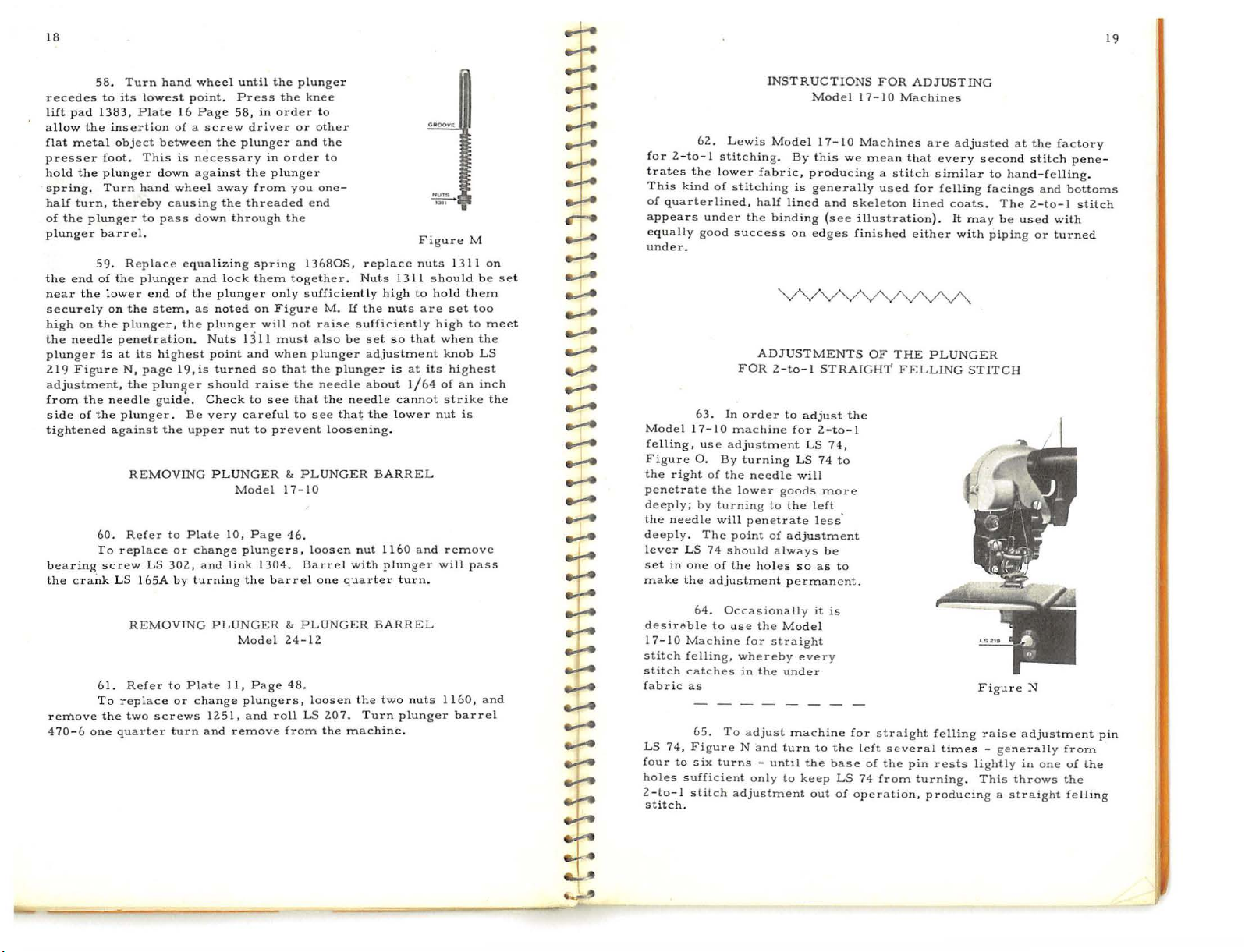
56. Loosen
own
accord
in
the
57. To
groove
on
the
ung
er
from
presser
i.nsert
in
notch
both
and
may
new
the
on
turning.
nuts 131
be
foot
.
plunger,
plunger
the
inside
1,
Figure
removed
place
to
the
of
the
by
front.
plung
M,
raising
same
The
er
and
in
groove
barrel,
the
it
the
plung
up
through
plunger
thereby
in
er
the
releases
the
barrel
plun
ger
keeping
Page 11
18
19
pad
ll
ow
the
metal
the plunger
turn,
the
end
t he l
on
needle
Figure
the
of
crank
emove
70-6
58. Turn
plunger
59.
the
To
one
recedes
liit
a
flat
presser
hold
spring.
half
of
plunger
the
near
securely
high
the
plunger
219
adjustment,
from
side
tightened
bearing
the
r
4
to
1383,
insertion
foot.
Turn hand
thereby
barrel.
of
ower end
on
the
is
needle gui
against
60.
screw
61.
To
the
hand
its
lowest
Plate
16
object
Replace
the
plunge
penetration. Nuts
at
N,
plunger
Refer
replace
LS 165A
replace
two
quarter
of a screw
between
This
is
down
wheel
causing
to
pass
equalizing
plunger
the
the
Refer
of
stem,
r ,
the
its
highest
page 19,
plun&er
de.
. B e
the
REMOVING
to
or
LS
302,
by tur
REMOVING
to
or
screws
turn
wheel
until
the
point. Press
Page
58,
driver
the
plunger and
necessary
against
down
and
th e p
as noted
is
upper nut
Plate
cha
Plate
change
the
away
the
threaded
through
lock
lunger
plunger
1.3
point
and
turned
should
Check
to
very
careful to
PLUNGER & PLUNGER
Model
10,
Page 46.
nge
plungers,
and
link
ning
the
PLUNGER & PLUNGER
Model
11,
Page
plungers, loosen
1251,
and
and
remove
plunger
the
in
orde
or
in
order
plunger
from
you
the
spring
them
together. Nuts 1311
only
on
Figure
will
not
11
must
when
so
that
raise
the
see
that
to prevent
17-10
1304. Barrel
barrel
24-12
48.
roll
from
knee
r to
other
the
to
one-
end
13680S, replace
s u
fficiently high
M.
If
the
raise
sufficiently
also
be
plunger
the
needle
that
loosening.
nut 1160
with
quarte
the
207. Tu
the
machine
set
ustment
about
the lower
BARREL
plunger
BARREL
two
r n
plunger adj
the
needle
see
loosen
one
LS
Figu
nuts 1311
to hold
nuts
are
so
that
is
at
1/64
cannot
and
r tu r n.
nuts
plunger
.
should
set
high
when
knob
its
of
strike
nut
remove
will
1160,
r e M
them
too
to
the
highest
an
is
pass
barrel
on
be
meet
LS
inch
the
and
set
._!...
.......
....-..
e.-A
......
......
......
~
......
........
........
........
~
......
.,_;.4
......
......
~
......
.,!....
~
~
~
.-....
.,:;..4
.......
.......
..-....
~
~
62. Lewis
for 2-to-1
trates
the lower
This
kind
of
quarterlined,
appears
equally
under
Model I 7-10
felling,
Figure
the
penetrate
deeply;
the
deeply.
lever
set
make
desirable
17stitch
stitch
fabric
LS
four
holes
2-to- 1
stitch
under
good
.
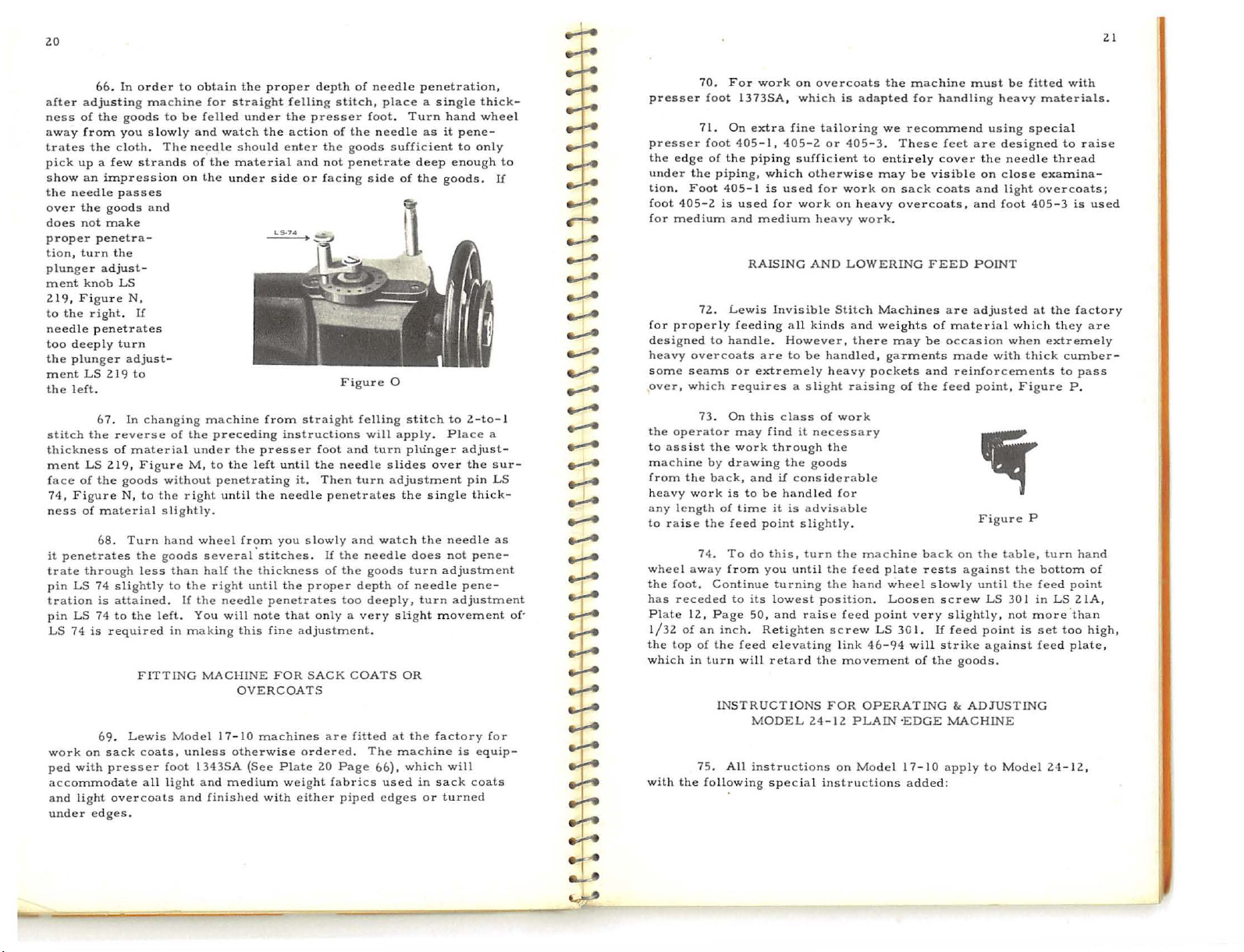
63.
use
0 . B y
right
of
by
needle
The
LS
74
in
one
the adjustm
64. Occasionally
10
Machine
felling,
catches
as
65.
74,
Figure N and
to
six
suffi
stitch
.
INSTRUCTIONS
Model
stitching.
fabric,
of stit
ching
half
the
binding
success
ADJUSTMENTS
FOR
2-to
In
order
machine
adjustment
turning
the
needle will
the
lower
turning
will
of
to
To
turns -until
cient only
to
penetrate
point
of
should
always
the holes so
ent
use
the
for
straight
whereby
in
the
adjust
adjustment
Model
17-10 Machines
By
this
we mean that
producing a stitch
is
generally
lined
and
skeleton
(see
on
edges
- 1
STRAIGHT
to
adjust
LS
s m
left
less'
it
to
the
out
the
74,
74
to
ore
be
as
to
is
the left
base
LS
of
operation, pr
for 2-to-
LS
good
the
adjustment
permanent
Model
every
under
machine for
turn
to
keep
FOR
used
shed
OF
straight
of
the
from
ADJUSTING
Machines
for
lined
either
THE
FELLING
several
pin
turni
are
adjusted
every
similar
felli
ng facings
coats. The 2-to-1
with
PLUNGER
STITC
fell
ing
times -generally
rests
lightly
ng .
oducing a straight
I 7- 10
illustration). It may
fini
1
.
74
second
to
be used
piping
Figure
raise
This
at
the facto
s t
itch
hand-felling
and
with
or
turned
H
N
adjustment
in one
throws
ry
pene
.
bottoms
stitch
from
of
the
the
felling
-
pin
Page 12
20
after
ness
away
trates
pick
s h
the
over
does
proper
t io
plunger
ment
219,
to
needle
too
the
ment
the
stitch
thickness
ment
face
74, Figure
ness
it
trate
pin
tration
pin
LS
work
ped
accommoda
a
under
66.
adju
of
the
from
the
up a few
ow
an
needle
the
not
penetra-
n,
turn
knob
Figure
the
right.
penetrates
deeply
plunger
LS
left
.
67. In
the reverse
LS
of
the
of
penetrates
through
LS
74
LS
74
74
is
on
with
nd light
edges.
In
order
sting
machine
goods
you
slowly
cloth. The
strands
impression
passes
goods
and
make
the
adjust
-
LS
N ,
If
turn
adjust-
219
to
changing
of
material
219,
Figure
goods
N,
to
Turn
the
less
slightly
attained.
to
the
left. You
FITTING
coats. unless
t e
all light
the r ighl
slightly.
material
68.
is
required
69. Lewis
sack
presser foot
overcoats
to
obtain
for
to
be
felled
and
watch
needle
of the
on
the
machine
of
the
preceding
under
M,
without
hand
goods
to
penet
until
wheel
several.stitches.
than
half
to
the
right
If
the
needle
M.ACI-IINE
1343SA
and
and
finished
will
ing
in mak
Model 17- 10
the
proper
straight
under
t h e
should
enter
material
under
side
from
instructions
the
presser
the
left
until
rating
the
needle
from
you
the
thickness
until the
penetrates
note
this
fine adjustm
FOR
OVERCOATS
machines
otherwise
(See
medium
Plate
weight
with
depth
of
felling stitch,
the
presser
action
the
and
not
or
facing
straight
foot
the
it. Then
slowly and
If
of
proper
that
only a very
SACK
ordered. The mac
20
either
foot.
of
the
goods
penetrate
side
Figure
felling
will
and
needle
turn
penetrates
the
needle
the
goods
depth
too
deeply,
ent.
COATS
are
fitted
Page 66),
fabri
cs
piped
needle
needle
turn
penetration,
place a single
Turn
hand
as
sufficie
0
apply.
slides
adjustment
watch
of
slight
at
used
edges
it
nt
deep
of
the
goods
stitch
to 2-to
Place
plunger adjust-
over
the
single thi
the
needle
does
not
turn adj
needle
turn
movement
OR
the
factory
hine
which
will
in
sack
or
turned
thick
wheel
pene
-
to
only
enough
.
If
-1
a
the
sur-
pin
LS
ck-
as
peneustment
pene
-
adjustment
for
is
equip-
coa
ts
to
-
of·
~
~
::t:
...,:..e
........
~
c.-A
.........
....._..
....._..
.........
~
.........
.......
.........
.......
---1
..,
.,:.....
~
J...
~
~
c,.:...e
:t.:
:t:
pre
presser
the
under
tion. Foot
fool
f
for
designed
heavy
s
over, which
the
to
m
from
heavy
any
to
wheel
the
has
Plate
1
the
which
with
70.
sser
foot l37
71.
foot
edge
the
405-2
or
medium and
72.
properly
overcoats
ome
seams
73.
operator
assist
achi
ne
by drawing
the
work
length
raise
the
74. To
away
foot. Continue
receded
12,
/32
of
an
top
of
in
turn
75.
the
following
For
work
3SA, which
On
extra
405-
of
the
piping,
405
is
used for
Lewis
feeding
to
handle. However,
or
requires a slight
On
may
the
work
back,
is
of
time
feed
from
to
Page 50,
inch.
the
feed
will
INSTRUCTIONS
All
fine
l ,
405-2
piping
which
-1
is
used
medium
RAISING
Invisible
all
are
to
extreme
this
class
find
through
the
and
if
to
be
handled
it
is
point
do
this,
you
turning
its
lowest
and
Retighten
elevating
retard the
MODEL
instructions
special instruct
on
overcoats
is
tailoring
or
sufficient
work
it
considerab
until
405-3.
otherwise
for
work
on
heavy
heavy
work.
AND
LOWERING
Stitch
kinds
and weight s
be
advisab
slightly
turn
raise
there
handled, garments
ly
hea
vy
raising
of
work
necessary
the
goods
for
le
.
the
the
feed
the
hand
position.
feed
screw
link 46-
movement
FOR
24-12
PLAIN ·EDGE
on
Model 17-
the
adapted for
to entirely
machine
OPERATING & ADJUSTING
machine
we reconune
These
may
be
on
sack
overcoats,
Machines
may
pockets
of
the
le
plate
wheel
Loosen
point
very
LS
30
I.
94
will
of
ions added:
back
mu
st
nd
using
are
on
and
and
POINT
adjusted
on
point,
Figure
the
against
until
LS
point
against
to
with thick
be
designed
need
close
light
foot
al
which
when
Figure
table, turn
the
the
30 I in
is
Model 24-12,
handling heavy
feet
cover the
visible
coats
FEED
are
of
materi
be
occasi
made
and reinforcements
feed
on
rests
slowly
screw
slightly, not
If
feed
strike
the
goods.
MACHINE
10
apply
fitted with
materials
special
to rai
le thread
exa
mina-
overcoats;
405
- 3 i s
at
the
factory
they
ext
rem
cumber
to
pass
P .
P
hand
bottom
feed
point
LS
21A
more.than
set
too
feed
plate,
21
.
se
used
are
e ly
-
of
,
high,
*
--r
·
......
~
Page 13

22
76.
We
and
not
by
hand.
a
nd
the
the prod
shown
which
joining
ormed
stitch
se adj
line
77.
inch
78.
vas
seam,
79. Pl
80.
by
8 1.
ustment
stitch
Baste
from
on
in
is
the canvas
taking
through one
with hand basti
and
5/16
the can
as
basting
Q,
of
f
one
canvas, giving
u
felling
recommend
Machine
of bast
ing
ng .
uction is
the
1n
placing
the left
Figure
which
ace
directly under
The
the
To adju st n
deeper
is
Furthermore,
far gre
sack coats
edge.
the
of
Q.
See
is
the
the
edge
NEEDLE
operation
t o
one
sti
- ha
appearance
pin
LS
74,
and
BASTING
all
edge
basting places
more even
ater
.
1/4
inch
F i
gure
work
on
th e
arm,
that
guide No.
seam
between
of
the
the
foot.
PENETRATION
of
felling
the
facing
tch
into
the
lf
the
thickness
of
eedle
penetrati
Figure
to
the
left
basting
than
machin
the stitches
ordina
e basting
from
the
work
·.
Q
the machine ,
which
is
on
1576
the canvas
garment
with a zig-zag
sketch
N.
the
canvas
canvas
shown
on
Turn
for less
in the
only and
of
the
in
the
to
penetration.
be done
rily
can
is
edge
and
pla
ce
the
outside
is
dir
groove
to
the
stitch.
goods
at
top
cloth
the right
by.
machine
closer together
be att
eco
overcoats
garme
of
the machi
above
facing
of
plate
front
Th
i~ stit
through
the
facing
to
make
aine
nomical
nt
the
Figure
is
w1th
the
more
the
ectly
and the
coat
alternatmg
and
of page 23.
on
d
with
sid
that
~h
the
side,
is
ne ,
e.
.J,..
±
.J...
.......
c,..;A
e,..:..e
...:--e
..,_.....
.......
.......
~
~
~
~
...-..
~
~
...,:....
~
~
adjustment
which,
crown
allows
ad
through
deep
against. The
unless
finish.
penetrate
ing
slide
are
coats
coats
SACK
~
:t=
._:...
__.
--r-
~
e-':'1
82. To
screw 1493,
in
turn,
adjusting
the
nee
83. On
justment
knob
fitted
1571A-Foot
1578)
1579)
I
584 Plu nger
s o
part
penetration
you
desire
84
.
If
the
LS
2 1
over the
85. Lewis
with
.
86. Parts
to
overcoats
COAT
Plunger
Comple
adjust needle
causes
screw 1493
dle
to
penetrate
overcoats
as
to
permit
of
the
undergoo
is
not
needle
canvas only, lower the
should
to
produce
the
needle
9, Figure
facing
goods
Model
presser foo
for
and
PAR
TS
te
Sprin
g
penetration
Figure
the
necessary
M,
cha
vice
Q ,
needle
to
the
more deeply
it
is esp
needle
ds
on
not ent
what
penetrates
to the left
.
24-12
machines, unless
t 1
571A
nging
Lewis
versa
TOPCOAT PARTS
1
1593A -Foot
1591)
I
592)
1310
Plunger
in
to
to
penetrate
left
ecially desira
to
the
or
er
is
the
and relating par
are
Plung
Complete
the
the
right
tends
to
into
pass
through
canvas
desirable, and
the
fore-part
termed
plunger
Model 24-
as a "pri
facing
by
sufficie
as follows:
er
Spring
canvas, turn
to
stop
the
deep
ly. Turn
the
canvas
to
make
canvas and
On
sack
should
on
sack
cked edge"
time
plunger
mit
se
for
machine
plunger
plunger,
it
work
nger Spring
less
raise
the
b l e
the
side.
at
the
turning
nt
to per
otherwi
ts
12
OVERCOAT PARTS
1
593SA -Foot
1591-1/2)
1592-1/2)
1310 Plu
crown
.
the
above
coats
be
guarded
coats
should
the
needle to
specified
on
from
Plunger
Complete
rise,
ing
which
this
adjust
sack
sack
23
·
-
,
~
Page 14

24
~
~
25
87. A special mechanism
automatic
dimples
om
face
two
especially
is
the canv
automatic
stitches
when
ension
024.
are
note
cam
showing
felling
felling
or
88. The
intermittent
rele
ase
or
on
side
of
or
pieces
This
mechanism
desirab
thin
goods
.
89.
To
dimples
taken
in
is
made
is
made
between
as
tension
90. The
tension
from
is
held
under
the
two
91.
in
gear
92.
release,
that
on
the end
tension
layers
CAUTION:
is
properly
In
case
when
the
throwing
Adjustment
obtained. An
the
tension
vent
fr
or
when
ing
gether.
is
when
weight
tions
that
portion
facing
thread
and
the
normal
the
thread
loop
holds
screws
illustr:\tion. We
m«:ans
mechanism
factory.
:
I
90
to
the
AUTOMATIC
purpose
is
to
pre
indentations
the
outside
the
material
b.lind
stitch
of
cloth to-
le
light-
avoid
indenta-
the
stitch
the
canvas
with a normal
with a very
the
two layers of
are
not
drawn
release
purpose
is
to
securely
loosening.
normal tensi
automatically
together a very
FigureR,
especially
automatic
timed
it
does
timing
is
then
approximate
the
take-up
of
shaft
Do
1024,
the
this
See
Plate 7 Page
of
-
-
tension
loose
tightly
.
in
setting
fasten
While
Not
caution
tension
when
become
is
done
made
is
1552
TENSION
used
tension
material.
together
the
the
the
on
until
is
loose
under
any
above
you
the
necessary
by
until
the
method
at
its
should
RELEASE
40
on
Lewis
and
the
in
order
In
through
stitch
in
bobbin
stitch
is taken
the
hook
released,
tension
circumstances
indicated
on
this,
release
loosening.the
highest
machine
results
of
making
be
horizontal
out
to
point, the
Model
stitch
other
the
thread
giving
by
as
is
time
outlined
24-12
that
to
allow
words,
the
canvas
and
in
has
discharged
the
.
arrow
to
loosen
of
time,
assembled
the
screws
this
and
Machine
FigureR
is
taken
sufficient
the
operation
with
to
prevent
the
facing
thread
,
loosen
in
the
gear 1024
which
in
automatic
in
in
Paragraph
adjustment
single
lobe
against
in
facing
a
the
which
set
our
gear
of
the
is
of
the
:t:
.
~
tension
it
which
K, as
will
staff
generally
93. The
gear
per
instructions
1553
1024
(See
be
necessary
timing
is
mounted,
Plate
of
the
in
paragraphs
7,
page
to
hook,
is
provided
40). After
retime
which
45, 46,
the
by
hook.
is
the
making
actuated
lower
47
.
by
gear
this
the
1028,
adjustment,
shaft
on
Figure
.J..
~
r.-e
..,:..e
.,.L.
.,_;,.e
.;!..
.,_!..
.......
.......
.......
the
needle
edge
in
causing
occurs,
guide, Fi
very
small
guide
is
smooth
eliminate
94. After
will
the groove
thread
we
gure S which
not
the
sharpness.
considerable
be
inclined
of
the
breakage.
recommend replacing
cost.
However,
conveniently
groove
with
BREAKAGE;
to
needle
When
can
be
if
procurable,
emery
HOW TO
service
cut a sharp
guide
,
this
needle
done
at
cloth
a
needle
to
new
OVERCOME
FigureS
THRE
AD
~
95.
When
through
sharp.
and
~
J..
thread
needle
......
......
~
..,:.-e
..,:.-e
~
--re
~
--1
--1
tight
in
same
bind
in
14,
is
the
loop
48
Page
correctly
tangled
time
or
over
We
refer
guide,
.
96.
Thread
the
bobbin
as
the
bobbin
97. Thread
improperly
from
IS
for
tinled
98
.
If
in
the
thread
which
to
thread
the
bobbin
the
needle
timing
to
the
bobbin
bobbin,
breakage
the
thread
the
following
take-up,
breakage
case. While
becomes
case. Old
breakage
timed,
the
plunger.
thread
causing
at
the
hook.
is
wound
passes, to
parts:
bobbin
may
this
bobbins
may
the
proper
Before
See
Paragraphs
breakage
occurs,
be
caused
is
not a frequent
old,
it
should
be
caused
point
time. See
timing
too
full,
will
check
up
see
needle
case
by
has a tendency
be
if
of
53, 54,
or
resu
on
if
they
guide, needle
retainer
the
bobbin
discarded
the
hook,
the
hook
Paragraphs
hook, see
and
if
the
thread
lt .
the
parts
have
1057
being
condition,
to
warp
.
Figure
to
fail
that
55
Page 17.
has
become
clamp
and
at
and
J,
to
pick
46,
needle
become
the
too
the
page
up
47,
is
--r-
:t:
~
..4
.,....
.,....
....:-e
~
~
~
may
as per
needle
99. On a new
be due
to
instructions
100. Thread
threa
·d
is
machine
accumulation
in
Paragraph
breakage
either
too
just
put
of
oil
in
the
9.
may also result
loose
or
too
in
operation,
hook
tight.
which
if
the
Check
thread
must
tension
up on.
breakage
be
removed
of
this
the
.
~~~======~========~==
···
~-~
~=====---~------
---~------
Page 15

26
revolution,
after
just
the
needle
tion"
breaks
is
too
fast, insu!Iicient
on
the
thread
101.
If
that
discharging
thread,
may
cont
the
is
hook
to
thread
be
r o
ller
say,
it,
due
picks
if
or
breakage
to
several
tension
spring,
up
the
the
if
needle
hook
again
the
hook
will
things,
on
the
or a combination
thread
picks
completely
result.
among
needle
up
These
thread,
on
the
the
fails
"second
which
insufficient
of
these
hook's
needle
to
discharge
are:
.
second
thread
revolu
the
tension
27
-
hook
f
formation
may
stitches. Alw
guide
pletely
the
stitches
Paragraphs
!OZ.
oot, they
result.
103. Bent
while
in
needle
104. Occasionally
will
of a good
the
guide
due
If
the
ride
See
Paragraph
ays
entering
goods,
.
to
its
63
and 80-
SK1PPING
goods
are
with
the
loop
for
or
blunt
use a sharp
the
goods. Of
there
being
the
set
84.
not
needle
the
37
Page
needles
needle
should
plunger
too
STITCHES
being
properly
as
it
hook
low. Adjust
penetrates, preventing
to
pick
13.
are
frequently
and
see
course,
be
clearance between
may
be
up,
that
when
the
the
clamped
and
skipping
the
it
bea.rs
the
needle
cause
plunger
cause
the
of
under
stitches
of
skipped
on
the
is com -
needle and
skipped
higher.
the
the
needle
See
.....:--
........
........
.,.!..
........
.,.L.
~
c)..
..,!..
~
.,..
---r
.,..
.,.
.......
......
.....
......
.......
.....
~
~
--r
,...
..,:....-
.,!...
.....
..-..
,
__
,
Page 16

M
ODELS
17-
24-12
10
MA
IN SHAFT
GROUP
N
0:
LS 6
LS.
LS
LS
cs
LS
1005
1020
1025
1031
1147
11
95
7A
12
2 10
320-1/2
671
Feed
Adjuster
See
LS7A
F
eed
adjuster
composed
Main
Shaft
Feed
Elevating
Set
Screws
Ve
rtical Plunger
Set
Screw
Set
Screw
Set
Screw
Set
Screw
Spot
Screw
Spot
Screw
Set
Scr
ew
Set
Screw
.
crank
of:
LS
Bushing,
for
for
LS
for
Gear
to lock
for
Gear
for
for
in
Arm
in
Arm
Crank
disc
6, and
right.
Eccentric.
Hand
Wheel
Shaft
210
.
1200
Feed
LS
Gear
LS
Feed
Eccentric LS
for
for
Disc,
assembly,
Guide
Driving
and
Eccentric
671.
671.
LS 12.
1196
.
Not
1802
120
MAIN
Mode
Sold
Pin
.
Gear
I.
ls 1
.
1208.
.
1212.
210
SHAFT
7-10
.
.
GROUP
and
1196
1200
1201
1203
1210
1211
12
12
1
213
1214
1802
14-324
1
8-748
24-12
Main
Shaft
Gear
on
Main
Model 17-10
Gear
on
Main
Model 24-12.
Spot
Screw
Spot
Screw
Set Scr
Feed
Screw
Spring
Hand
Main
Screw
Main
ew
Adjuster
for
for
Wheel.
Shaft.
(left
Shaft.
Bushing,
Shaft
.
Shaft
for
1200
for
LS 7A.
for
LS 7A.
Eccentric
adjusting
1212,
hand
thread)
(2)
114-154
10255
left
.
for
Driving
for
Driving
and
1201.
.
1212
.
used
.
in
1
end
head,
head
of
,
Page 17

MODELS
17
-10
24-12
HEAD
SHAFT
GROUP
1
001
1003
1
005
1139
102551
cs
337
cs
510
1001
1002
1002-l/2
1003
1004
1005
1139
11
43
114
4
11
46
1146S
HEAD
Models
Clamp
·
Needle
S
Set
Head
Head
H
Head
Screw
End
Thrust
Needle
Sp
Spot Screw
Set
Head
Crank
ot
Screw for l 00
Screw
Driving
et
Screws
Screw
Main
Main
Main
ead
Main
Main
SHAFT
17-10
for
Washer
.
for
Gears
for
1001.
Stud.
for l 004.
for
Gears,
Shaft
Shaft
Shaft
Shaft
Shaft
GROUP
and 24-
Washer
for
1139.
1.
1143, 1144,
1143, 1144,
Drive
Gear, Model17-l0.
Drive
Gear,
Hook
Drive
Hook
Drive
12
CS
510
.
Model 24-12.
Gear,
Gear,
1146
and
1146 and
for
Model
for
Mode
l l
46S.
1146S
17-10
l -24-
.
.
12.
Page 18

MODELS
17-10
24-12
1030
1
028
H
OO
K DRIVE
GROUP
1024
1024
1025
1026
1027
1028
1029
1030
1031
1551
\\1
H
OOK
Models
Hook
Spiral Gear
Set
Screws
Hook Timing
Collar
for
Bevel
Gear
Set
Screw
S
et
Screw
Set
Screw
Hook
Shaft
Spot
Screw
Hook
Timing Shaft
DRIVE
17 -
10
for
Bevel
Shaft
Hook
Timing
on
Shaft
for
Bevel
for
Collars 1027
for
Gear
Bevel
for
1030
GROUP
and 24-
.
Gear 1028
for
1026
Gear 1030
1024
Gear
and
for
12
Model
Shaft
and
.
.
1024
Model
(4)
17-1
(2)
1551.
.
use
.
24-
102551
\-H
.
0.
used.
d.
12.
Page 19

MODELS
17-
10
24
-12
OO
K _
H
COMPLETE
10
55
10
40
416
1170
A
-11
10
34A
HOO
K WITH
S
HAFT ONL
HOOK
Y
GROUP
10
3 7
1
039
047
1
18- 719
445-25
1041
10
10
18
1•
A _ BOBBIN CASE
COM
4 6
43
-912
BOBBI N
PLETE
l034A
1
035
1036
1037
1039
1040A
l041A
1041C
1
043
1
046
Hook
without
Needle
Screw
Hook
Gib.
Screw
Hook
complete,
1035,
Bobbin
Composed
1046
Latch
Spring
Tension
Tension
and
Thread
for
1035,
for I 03
{3)
1036,
Case,
and
case.
Spring
Screw
Guard
or
Guard
(3)
used.
7,
(2)
used.
composed
1037
right
hand,
of:
18-912,
for 1041A.
for
1041A.
for 1043.
Gib.
and
complete
1043
(Not
for
of
{2)
Models
l040A.
1034A,
1039.
and
Shown)
HOOK
.
GROUP
17-10
. 1
and
1047
1053
054
1
055
1170
18-719
18-912
22-241
26-148
51 -
19
416-
11
445-251
24-12
-H
\1\\\
Bobbin
.
Stop
Pin
for
445-25
Spring
Spring
Bobbin
Latch
Adjustable Hook
Bobbin
Clamp
Bearing
Clamp
Hinge
(Not
spring
for
445-25
Pin
for
Screw
Screw
Screw
Pin
for
Shown)
Ejector in
in
1041A.
Case Rel
Pin 1049.
for
for
Bobbin
1.
1054
Hook
for
1043.
104
(Not
Bushing
ease
114-15
4
102551
\\\1\lr
1.
.
Bushing
445-251.
Case
latch
1A.
(Not
Shown
)
complete
complete
416-11.
51-19.
Shown)
.
with
Page 20

MODELS
17-10
24-12
1
036
10
1015
1
432A
CO
MPLETE
16
NEEDLE DRIVE
1008
~~1060
li
GROUP
.
1
006
NO.
-
MODEL
17-10
10065-24-12
11-l-11-l
-1-\ \ \
\-1-\--\
1006
l00
1
007
1008
1009
1010
10
1012
1014
1
015
101 6
10
36
1
056
105
1
060
1432A
1432-l/2A
t~\-\
6S
11
9
1 \-\ 1
NEE
Models
Need
Need
Needle
Ne
edle
Nut
Needle
Needle
Nut
Clamp
Needle
Needle
Screw
Bobbin
Needle
Needle
edle
Ne
101
Needle
DLE
le
Carrier
le
Carrier
Carrier.
Carrier
for
Carrier
Carrier
for
Screw
Clamp
Clamp
for
Case
Bar
Bar
Clamp
5, 1016
Clamp
DRIVE
17-10 and
Studs
1011.
cla
GROUP
24-12
Connecting
Connecting
Driving
1008
and
1010
Bearing
Bearing
for
1432A.
Thread
Thread
mping 1015 and
release
Bushing
Bushing
complete, composed of:
and 1036
with
Guide Pla
Guide
lever
(left
(right
.
Pin
.
Link
for
Link for Model
Stud
.
.
Stud,
left.
Stud,
right.
t e,
Pla
te,
101
6.
.
hand
)
hand
)
Model
lower.
uppe
1432-l/2A
114-154
102551
17-10.
24-12,
r.
Page 21

MODELS
17-10
24-12
TAKE-UP
LEVER
GROUP
w
CX>
1023
1019
\-\-1-\-t
-\ \-\-\
1
018
A
10 19
1020
1021
1022
1
023
445-234
\-
TAKE-UP
Models
Take-up
Take-up
Set
Screw
Collar
Set
Screw
T
ake-up
Take-up
1-\
LEVER
17-10 and
Lever comp
Lever
for
for 1019
for 1021
Lever
Lever
1021
1022
GROUP
24-
12
lete,
Bearing
101<;.
.
.
Slide Block
complete, for
for
Shaft.
.
Model 17-
Mod
el
24-12.
10.
1
0255
1
Page 22

MODELS
17-10
24-12.
THREAD
TENSION
GROUP
....
0
1
552
MODEL
24-12
~
\-
1+
1182A
118
1
1
442
1132
1134
1-t \-t-t
,1
MODEL
Ht
-
181
20-60
1188
1189
68-19
114-1
102.551
H-\-\
54
cs
LS 314
'
LS
10
8 1
1
132
11
34
11
81
11
82A
11
83
11
85
118
1187
231
330
6
Nut
for Screw
Screw
for
Set Screw
Set Screw
T e
nsi
on
24-12.
Knurled Nut
thread tension, Model 24-12.
Pigtail
Te
Tension
Washer
Thread controller Staff
Thread
thread
nsion
1558S.
Latch
1555
.
in
head for 68-1
in
Head
for 1182A
Spring
Staff with
Dis
for 68-1
controller Spring
Front on 1553, Model
{2)
used
on
Eyelet
.
Pin,
c.
9
1553
Model 17-10.
Barrel.
THREAD
9.
.
.
Models
to adjust
TENSION
17-10
and 24- 12
1188
11
1442
1552
1
553
1
554
155
1556
1
557
1558S
20-6
21-284
68-19
89
5
GROU
0
P
Thre
Sc
rew
Loc
Gear
T
ension Staff,
Tension
24-12.
Latch
Adjusting
Lock N
Pilot
Knurled
thread,
Tension
Thread contro
ad
controller Staff Sto
for 1188.
ating
Pin
for
and
Cam
Shaft, Model 24-
Model
Spring rear
for
1552, Model
Nut
for
ut
for
Screw
155
for 1553.
Nut
for
Modell7-10.
Spring,
ller
adj
Model
Dis c 11
24-12.
on
1553,
6.
ust
Staff.
83.
1553,
24-12
Model
ing
17-10.
p .
Model
.
24-12.
tension
12.
of
Page 23

MODELS
17-10
24-12
SKIP
LSI20
LS
LS
LS39
STITCH
672A
295
3
PLUNGER
GROUP
LS76
LS7
4
LS
7 1
18
-736
LS70~
LS
70-1/2
LS
71
LS
74
LS
75
LS
76
LS 120
LS
294
LS
295
cs
32
LS
393
LS
670
LS
672A
102
5
1031
1158
18-736
8
\-11
-
SKIP STIT
Models
Bearing
Skip
Pin
for
Spring
Nut
for
Vertical
Cam for 2-to-1
Ro
ll
for
Clamp
Bearin
Spiral Gear
Cam
Set
Screw
Spot
Screw
Sc
rews
S
crew
\
\-\
CH
PLUNGER
17-10 and
Block
Stitch
Skip
for
Skip
S c
g Scr e w f o r Cam
Roll
(2)
in
fo r
Adjusting Cra
Stitch
Skip
Stitch
Stitch
Shaft
for ·Plunger
S k
Skip
ip
Stitch
rew for LS6
on Ver
Block
with
for
Spiral Gear
for
Spiral
used
for
end
of
Shaft
-\-t
~
~
GRO
UP
24-12
Vertical Shaft.
nk.
Crank.
Crank
.
Adjusting
Stitch.
Cam.
72.
tical Sha
Clamp
Gear
LS
LS 120, for
Adjuster
Roll
ft
Screw.
LS
LS 6 70.
70-1/2.
Crank.
L S
LS 120
670.
114-154
10255
1
t t t 1 t-\ \ \ \-\-\-\ 1 }
.
295.
.
Crank
LS
71.
Page 24

MODELS
17-10
24-1
2
10
1073
1074
LS
1221
1220
72
509
t
HOOK COVER
1072A
COMPLET
COVER
E
0
GROUP
1073
1075
STITCHI
NG
HEAD COVERS
t\
ARM COVER
LS 50S'-l/2
1066
1067
1071
107Z
1072A
1073
1074
1075
1220
1221
PLATE
\-\
Models
Cover
Stitching
Stitching
Knurled
Cover
Cover
of
Screws
Thread
Screw
Screw
Spring
COVER
17-10 and
Plate
Screw for
(only),
for
: 1
072,
(2)
Clip
for
for
Washer
GROUP
on
top
Head
Cover,
Head
Cover,
for Hook Gears
Hook
Gears, complete,
1074,
and
used
for
and
Cutter
1074.
LS
509-1/2
for L S
24-12
of
Arm.
Model 17Model
stitching
1075
attaching
.
.
509-1/2
.
24-12
Head
.
1072A
.
10.
.
Cover.
Comp
to
ose
Head.
1
02551
d
Page 25

MOD
17
- 10
1263C
1256
1
671
EL
---~
FEED
FEED
'
PLATE
AND
PLUNGER
GROUP
....
0
LS
23N
LS
l30A
LS
135A
LS 165A
LS
225
LS 302
317
LS
LS
395
FP 53<;
LS
674
11
60
124
9
12 51
1254
1256
1260
1261
1262
Feed
and
Feed
e l
evating
complete
Feed
rocker
Plunger
Guide
Bearing
C1ampscrews
Screw
Clamp
Plun
Nut
B
ear
Bearing
Spring
Feed
Bearing
Feed
Hin
elevating
pin
screw
for
Model 17-
screw
ger
Frame.
for
bearing
1260
and
ing
stud
screw
pin
reta
screw
link
.
ge
pin
plunger
.
sha
in
1273
for
clamping
10.
for
1303.
in
for 1256
ini
ng
for 126
F
bearing
shaft
ft
with crank
shaft
for
for 1304
LS
work
Feed
screws
LS
l30A
in
1669
.
spring
for
1261.
1.
EED, FEED
block.
with
crank
.
with
crank
feed
spring
.
23N.
plate
Plate
Yoke 1415
LS 302, 1249,
for
link
for
link 46- 94.
.
PLATE
.
LS
LS 22,
46- 94.
M
odel 17-10
405.
.
& P
LU
1263C
12
63C
1303
304
1
1
309
1311
l
3680S
1
413
1414
1415
l 4
17A
166
:.1
1671
1
672
1673
1
677A
24-288
46-94
NGER
A
GROUP
Feed,
3/32
pitch
Feed
complete,
1262, 1263
Bear
ing
Plunger
Plunger
Nut
Plunger equalizing
Feed
Scre
Feed
Feed
1413, 1
Feed
Bearing
Roll
Bearing
Feed elev
Feed
Feed
stud
frame
barrel
for
plungers
plate
stem.
ws
for
feed
Plate
Yoke.
plate
yoke comp
415
and
elevating
screw
on Screw 1673
screw
ating
Plate
.
elevating link.
114-
10255
.
composed
C, 1671, 1677A.
for 1304.
link
.
spring,
(2)
spring
plate 24-
FP
bell
for
1677A
for
roll
link
with pin
of
heavy.
used
.
.
288
lete, composed
539.
crank
.
(2)
for
1273
1672
154
1
1256, 126
.
used.
.
.
1254.
1,
of:
Page 26

MODEL
24-12
FEED, FEED PLATE AND
"""'N'-J~""'""
PLUNGER
"7--
-...,.75"
15
6~
4
GROUP
~
6-
94
75"16
1
8-10
6
LS
·
LS
LS
LS
cs
LS
LS
LS
LS
1
022
1160
1249
1
251
1254
1256
1260
1262
1273
1311
1669
1671
1672
l30A
165A
207
225
232
317
395
396
629
Feed
elevating
complete.
Plunger
Roll
for
Guide
LS
405.
Nut
for
Clamp
Screw
Stud
for
Plunger
Screw
Nut for 1
Bearing
Bearing
Bearing
and
Roll
Spring
Feed
Retaining
Bearing
Hinge
pin
Feed
Spring
Nut
for
Feed
elevating
Bearing
Roll
on
Elevating
cam
Pin
in
stud
screws
for
clamping
LS
elevating
for 22-
249,
Stud
screw
screw
LS
pin
for
screw
for 46-
Plunger
Screw
Screw
shaft
slot
12
73
LS
396.
for
629.
21.
1251
in
LS
in
in
207.
1256.
Spring
for 46-15.
15.
Slide
{2)
bell
for
1673
FEED, FEED
with
Shaft
with
in
LS
629.
for
feed
blo
c k
work
cam
.
and
1260.
130A
1669
for
LS
62 9
Block.
used.
crank.
1677A
for
1273.
crank
crank.
spring
115:-3.
plate
for
link 46-
link 46-
for
470-6
{2)
used.
4-129
94.
PLATE
Model 24-1
16
1677A
18 -
18-125
21-2
22
.
23-291
24
46-15
46-94
68-3
94.
7
5-1
75-16
115-3
423-291
424
448-6
470-6
"'--'~-:::"-=-=-
& P L
UNGER
2
73
106
7
- 21
- 8
5
- 8
I 2 7 3
GROUP
Bearing
Feed
Screws
and 75-16.
Screws for
Springs
and 75-1
Pin
Feed
Feed
Feed
Feed
Sta
ff
Guide (left)
Guide
Feed
Feed
23-29
1677A.
Feed
{2)
24
Crank
feed.
Plunger
115-3
LS317
LS
395
1251
screw
elevating
for
for
for
separating
1/8"
plate.
Link.
elevating
for
feed
(right)
and
complete,
1, 46-
plate
18-106,
- 8 , 68with
sleeve
11
102
for
roll
link
with
feed
plate
guides
springs
feed
6.
pitch.
for
plunger
complete,
3, 75-15 and 75-1
shaft
21-27.
plate
feed
Link.
plate.
feed
for
plate.
feed
bearing
composed
15,
1256
{2) 18-125,
composed
and
pin
complete.
guides
p l
, 1
4-154
551
1672.
pin
1254.
75-
plate
ate
.
block.
of:
262,
{4) 2-127
6.
for
rocking
15
75-
15
guide
1671 an
of:
,
....
.....
H-1·
s .
d
~
-c>
Page 27

MO
17-1 0
24-12
DEL
Vl
FEED ELEVATING
GROUP
0
S
1206
12
1
160
51
LS 9
LS
20A
LS
20CMA
LS
21A
LS
130A
cs
200
LS
225
LS
301
100
9
11
60
1206
1244
124
9
1
25
1
1273
1288
1
669
1
672
1
673
46-94
4
7-115
1251
1009
M 0 D E L
17-
10-
24-12
LS
-
LS20CMA
.l:!Q_,__
111111111\ttttttt
FEED
ELEVATING GROUP
Plunger
Plunger
Plunger
Feed
Feed
Bushing
Guide
Clamp
Nut
Nut
Clamp
Bearing
Beari
Bearing
Feed
Bearing
Feed
Roll
Bearing
Feed Elev
Feed
Differential
Elevating
Elevating
Elevating
Elevating
for
Pin
Screw
for
Bearing
for
Bearing
Screw
Screw
ng
Stud
Screw
Spring
Screw
ele
vating
on
Screw
Screw
Elevating
LS
in
1273
for
for
for
in
for 46-
Slide Block
for
Bell
1673
for
ating
Lin
Connecting
Link,
Crank
Crank
Crank
Shaft
with
l30A
for
LS
20A,
Screws
Screws
connecting
LS
LS
l30A.
47-115
Crank.
for
roll
k.
with
Feed
1244
1251
9.
94.
.
1273
1672.
with
with
Screw
Crank
LS
and
Rod
--~
20
A
Screw
Screw
LS 301.
complete.
Spring
20CMA
and
1288.
and 1249
Rod 47-11
LS
9.
.
.
LS
LS 301,
LS
and
405
.
5.
301,
Model 17-10,
Model 24-12.
.
LS
21A
47-115
10
09
1
288
1009
LS
9
"d
t"
>
>-3
t1j
.....
!>.:>
1244
114
-154
10255
1
.
l
V'l
Page 28

MODELS
1
7-10
24-
12
1160
FEED
NO
. MODEL
1261 - 17-10
46-15-24-12
1260
.l!Q,_
LS135A
448-6
-
-
DRIVING
MODEL
17-10
24-12
GROUP
L
S201
1009
1206
1205
1
244
Ul
N
LS
LS
LS
LS
1009
11
60
1205
1
206
1
244
1260
1261
1262
46-15
448-6
19A
135A
201
301
Feed
Rocker Crank
Feed
Rocker
Bushing
Clamp
Nut
Nut
Feed
Clamp
B
earing
Bearing
Feed
Hinge
Fe
Crank with
in
Screw
for
Bearing
for
Bearing
Rocker Connecting
Screw
Screw
Screw
Link,
Pin for
ed
Link,
\\\-\
FEED
Shaft
Base
for
for
for
for
Model
1261.
Model
Shaft
with
for
LS
Screw
Screw
1205
1205
1261
17-10.
24-12
and
DRIVING
with
Screw
Crank,
LS
135A and
19A.
124
1260.
Rod
.
.
and
.
Pin
for
4,
.
46-15.
rocking
GROUP
LS
301.
Model
448-6.
17-10,
feed,
Model 24-12.
114-154
102551
t\\\\\\1\\\\'
Page 29

MODELS
1
7-10
24-12
1
005~
L
S675
\
~
PLUNGER CRADLE AND
MODEL
17-10
-
-
LS403S
LS403
L
S43A
24-12
ADJUSTING
GROUP
LS 219A
LS54
1
LS314
LS299
LS397
LSI65A
LS
ZOA
LS
ZOCMA
LS
43A
LS
165A
LS
Zl9A
LS
ZZO
LS 294
LS
299
LS
301
LS
314
cs
335
LS
397
LS
398
LS
403
LS
403S
LS
541
LS
675
1005
PLUNGER
Plunger
Plunger
Plunger
Plunger
Plunger
Nut
for
Cam
Lock
Clamp
Clamp
Screw
Pivot
Pivot
Plunger
Plunger
Plunger
Bearing
Set
Screw
Elevating
Elevating
cradle
elevating
adjuster
LS
for
produclJlg
Nut
Screw
screw
for
screw
screw
adjuster
adjuster
adjuster
center
CRADLE
complete
2 19A.
for
pivot
for
for
LS Z 19A.
for
LS
for
cradle
for
for
LS
MODEL
17-10
24-12
.AND
ADJlJSTlNG
crank
with
screw
crank
with
screw
with
with
aldp
and
(2)
Model
Model
crank.
LS
LS
used.
43A ,
bushings.
397
shaft
knob
complete
2-to-1
acrewa
,f..S
ZOA
LS
541.
294
LS
spring,
spring,
retaining spring.
LS
43A.
675.
-
-
with
stitch.
and
20CMA.
24-lZ.
17-10
'
~
LS
20A
LS20CMA
GROUP
LS
301,
LS
301,
shaft
and
LS
398.
,
Model
Model
pin,
114-154
102551
1-1
17-10.
24-12.
U1
U1
Page 30

MO
17-
24
DELS
10
- 12
PLUNGER
GROUP
m
CJD
26-1
1357
MODEL
17-10
ClD
1579
584
1
PLUNGER
MODE
24-12
GROUP
L
1
592i
102551
....
U1
1309
131 0
135
7
1578
1579
1
584
1591
591-1/2
1
1592
1592-1/2
26
- 1
P l
unger
unger
Model
barrel sp
barrel spring,
sharp edge,
17-10.
(long)
(short)
spring,
(short)
(short)
(long)
for
P l
Plunger
Plunger
Plunger
Plunger
Plunger
Plunger
Plunger
Plunger (long
Plunger
) u
light
r in g,
use
use
use
use
use
use
se
material,
heavy.
light.
use
with
feet 1343A,
with
Foot 1571
with
Foot
with
1578 and
with
Foot 1593A, Medium. Model
with
Foot
with
Foot
with
Foot
A,
light,
1571A,
1593SA,
1593A, medium. Model 24-12.
1593SA,
Model 17-
light.
1579.
heavy. Model
heavy.
10.
1343SA,
Model 24
1373A,
Model
- 12.
24-12.
Model 24-12.
24-12.
24-12
1373
.
SA ,
Page 31

MODELS
17-10
24-
12
KNEE
71-86
1029
PRESS
GROUP
1384
,,
.,
(
~
LS
LS
1
273
405
225
L
-26
21
MODEL 24-
".US
ED ALONE
MODEL 17-10
S405
ONLY
1272
WITH
FOR
12
ON
LS
51
LS
214
LS
225
cs
232
LS 324
LS
394
LS
405
1
029
1272
1273
1383
1383
-
1/2
138
4
1384-1/2
13
88
18-327
21-26
21-
286
71-86
1
388
KNEE
Feed
depresser lever
Lock
nut
Guide
pin
Nut
on
Stud
Screw
Set
Set
LS
for
for
Long
feed
Screw
Nut
for
Feed
spring
Knee
press
screw
Elevating
Clamp
Collar
Collar for
Screw
Short
Spring
Knee lift
screws
for
for
feed
on
PRESS
for
in
324.
LS
LS
spring
for
feed
for
levers
71-86.
21-286.
1388
spring
71-86
rod.
GROUP
LS
1273
51.
405
Collar
springs
slide
pad
.
1383.
for 1384
and
WHEN
.
324
.
for
spring
.
for
Modell7-10
1388.
LS
block.
(2) use
.
spring
for
Model
for 1383.
BOTTOM
MACHI
BACK
18-327
21-286
405
d.
21-286
LS
405.
and
24-12.
NE
ON
an d
21-26
.
VIEW
IS
TIPPED
HINGES
24-12.
.
102551
111
t
Page 32

MODELS
17-10
24-12
WO~K-SUPPORT
PLATE
GROUP
L
S39~
LS
for
MODEL
22
17-10
111
LS
ZZ
LS
395
4-12.9
l-1
WORK
LS395~
SUPPORT
Model
Work
Clamp
Clamp
Work
Support
PLATE
17-10
screw
screw
support
and
Plate,
for
for
plate,
GROUP
Z4-1Z
Model
LS
2.2..
4-12.9.
Model
MODEL
17-10
2.4-12..
4-129
for
24-12
.
114-1
54
102551
Page 33

MODELS
17-10
24-12
MISCELLANEOUS
LS
42
4145-6
1222
A COMPLETE
1224
1225
.....
co
LS
42
1222A
1223
1224
1225
1227
1326
1327
1328
132
9
1329-1/2
1330
1330A
4145
- 6
MlSCELLANEOUS
Model
17-10
and
Bracket
Spool
Screw
Post
Screw
Head
Hinge
Screws
Hinge
Shaft
Sc
Spool
Spool
Bobbin
for
holder
1224, 122
for
for
122ZA
for
cap
on
for
on
for
rew
for
Holder
Holder
winder
machine
complete.
5 ,
Spool
1224
screws
bracket
hinges,
base,
1222A.
1330
Disc
Disc
GROUP
24-12
hinge.
1329,
1329-1/2, 1330
Holder
.
Post
.
and
arm
LS
42
(8)
(2)
used.
on
1222A
Front, for
with
complete
Composed
1222A.
and
(2)
used.
used
.
.
hub
for
.
base
1222A.
1222A.
of:
and
screws
1223,
1330A
3652
.
.
114
-154
102551
Page 34

MO
2
DEL
4•
12
S
15
71 ~ FOR LIGHT MATERIAL
1593A FOR
1593
SA F
OR
PRESSER
MEDI
FOOT
UM
GROUP
TO HEAVY MATERIAL
EXTRA HEAVY MATERIAL
1073
1057
1573
1
351
1577
135
575
1
1073
1057
1573t
1058
6
·II
......
CD
114
1075
1351
1575
•154
1493
\
1
\
1778
1036
--'
892
~
/
1
\_1075
1351
1571 A
FOOT COMPLE TE
FOOT
1593
COMPL
A
ETE
\
\_
"--1575
1493
1
778
1036
892
1075
FOOT
1
593
SA
COMPLETE
102551
PRESSER
FOOT
Model 24-12
GROUP
892
1
036
1057
1
056
1073
1075
1351
1493
1571A
15
73
1573-1/2
1575
1576
1577
1593A
159
3SA
1598-1/4
177
8
6- 9
6-1
1
Bearing
Screw
for
Bobbin
Screw
Clamp
Clamp
Clamp
Clamp
Clamp
Adjusting
Press
Crown
Crown
Needle
Edge guide
Screw
Presser
P r
Needle
Retaining
Needle
Needle
case
for bob
screws
screw
screws
screw
screw
er
1058, 1075,
1778.
for
for
guard
for
1
058,
esser
1036
, 1
and
1778
guide for
guide
guide
screw
for crowns
retaining
retainer.
bin
case
for
for
needle
for
for
edge
for 6-11.
screw
for
Foot
for
(3)
1351,
157
1A and 15
1593SA.
for
1571A, 1593A
for
feet 1571A, 1593A
bobbin
Foot
1075,
Foot
057,
spring
case
for
(3)
1351, 1493, 1573, 1575,
for
1058, 1075,
1571A
for
for
1593SA.
(center)
1573
spring
presser
needle
light
medium
extra
1778.
retainer 105 7 (Right
foot.
guides
guard
guide
1576
crown.
wor
k,
complete.
1493,
Foot,
93A.
retainer
to
heavy
heavy
work,
(4)
1351, 1493,
and
crown
1593A
screw 1493.
for 1593SA.
and
1573-1/2
1598-1/4
1575
.
and
and
1057
.
and
(2)
used
Composed
1573, 1575, 1576,
1593SA.
1593SA
(Left
work,
side).
complete,
1576,
comp
lete. Composed
1573-1/2,
.
side~
6-9
.
.
.
1577,
of 892,
composed
1575, 1576,
1577,
Foot,
of
1036, 1057,
1598-1/4
1598-1/4, and
and
of
892, 1036, 1057,
6- 9.
6-11,
1577, Foot,
1778.
89~.
Page 35

MOD
17-10
ELS
PRESSER
1343A
1343
1373A
1373$A
FOR
SA FOR
FOR
FOR
FOOT
TURNED
LIGHT
MEDIUM
EXTRA
GROUP
UNDER
a MEDIUM MATE
MATERIAL
HEAVY MATERI
EDGES
RIAL
AL
1073
1057
1058
1346
1343A
FOOT COMPLETE
13
43SA
FOOT COMPLETE
PRESSER
FOOT
Model17-10
73
10
1057
GROUP
1
373B
1421
FOR
FOR 1
1373A
373SA
1073
FOOT
FOOT
114•154
11
"Cl
t""
>
..,
trJ
c:-:>
0
1- 1
1057
1058
1073
10
75
1343A
1343SA
1346
134
8-1/4
1348B-1/4
1349
1
351
1373A
1373B
1373SA
1421
18-281
Bobbin case
Clamp
Clamp
Screw
Presser
Foot, 1346, 1348-1/4, 1349
Presser
18-281, 1057,
Needle
Needle
Needle
Edge
guide
Screw
Presser
(2)
1058, 1075, 1346,
Edge
guide
Presser
105
7, (2)
Edge
guide
Clamp
retainer.
screws
screws for
for
Guard
guide
guide
for
screw
for
needle
foot
complete.
foot
for
(2)
.
for
for
for
foot
edge
guides
foot
for
for
1343SA and
foot
for
1058, 1075, 1346,
for
1373SA,
for
1057.
presser
guides
light
and
1058, 1075,
foot
1343A.
feet
1343SA,
1343A.
.
medium
extra
needle
foot.
1348-1/4
Composed
and
mediwn
1373A
work,
1348B-1/4,
13
73A.
heavy
work, complete.
1348B-1/4,
guard
and
1348B-l/4.
of 18-
1351.
Foot,
complete. Composed
1346.
281, 1057,
work,
complete.
134
6,
and 1373SA.
1351,
Foot
1351,
1348B-l/4,
and
Composed
Foot,
(2)
1058,
Composed
1351
of: 18-2
1373B,
1421.
of:
1075,
of:
and
81,
18-281,
1373B.
1057,
Page 36

MODELS
7-
1
FOOT
10
73
10
PRESSER
405-1 FOR
405
-2 FOR EXTRA HEAVY MATERIAL
40
5 - 3 FOR MEDIUM a MEDI
LIGHT
FOOT
a M
EDIUM
UM-HEAVY
GROUP
MATERIAL
MATERIAL
1
073
1057
1
058
1351
6
-I
1346
FOOT
405
COMP
-1
LETE
10
57
10
58
10
73
107
1
346
1351
6-1
6-4
18-28
75
-12
405
405-2
405-3
5
- 1
'U
t-<
>
...:j
trl
N
......
6 -4
6-1
1
058
18 1
075
281
1346
405-2
FOOT COMPLETE
405
- 3
FOOT COMPLETE
11
4-154
102551
P
RESSER
Bobbin
Screws
Cl
Cl
N
Cl
Plow edge and
1
9
Plow
C l
E d
Presser
Presser foot
Presser
case retainer.
for
amp screws
amp
screw for needle
eedle guard
amp
screw
edge
amp
ge
Composed
and 135
Composed
and
Composed
a
nd 135
and
screw
guide
foot
1.
1351.
foot
1. Use
1057
.
for
presser feet
. ·
for
plow
needle
needle
for
needle
for
feet
complete
of:
Foot, 6-1,
Use
with
complete
of:
Foot, 6-4, 18-281,
Use with
complete
of:
Foot
with
For
Piped
guide
edge
gui
de
gui
de
guard 1346.
, 405-1,
for
standard
for
standard
for
, 6- 1, 1
standard
FOOT
GROUP
Edges
.
.
guide
for
feet 405-1
for
foot
405-2
felling
18-281, 75-
plunger 1357.
felling
plunger
felling
8-28
plung
75-129
.
and 405-3
405-2.
and
405
- 3.
piped
edges
129, 1057,
piped
edges
75-129, 1057,
1357
piped
edges
1,
75-129, 1057
er
1357
on
on
.
on medi
.
light
{2)
ext
(2)
, {2)
.
r a
and
medium
105
8, 1075,
heavy
and
work
heavy
1058, 1075,
um
1058, 1075,
wor
13 46
.
134 6
work.
1346
k.
Page 37

MODELS
17-10
10
73
PRESSER
405-5
405-34
405-131
1
073
FOR
EXTRA
FOR
FOOT
SILK
a RAYON MATERIAL
LIGHT
KNIT
FOR SILK a RAYON
GOODS
GROUP
10
73
1073
....
0
1058
405-5
FOOT COMPLETE
1057
1058
1075
1351
405-34
FOOT COMPLETE
Silks,
PRESSER
Rayons and
FOOT
For
Modell7-l0
Knit
1057
1058
18-2.81
1075
1351
GROUP
Materials
FOOT
4 05-131
COMPLETE
114-154
102551
'0
t"'
>
>-3
rrl
[\:>
[\:>
1057
105
8
073
1
107
5
1
346
1348-1
1
349
1351
13
738
18
-281
405
- 5
405-34
4
05-131
/4
Bo
bbin
Screws
Cl
Clamp
Needle
Needle
Edge
Screw
Edge
Clamp
Presser
Presser
Presser
case
for
amp
screws
screw
guard.
Guide.
guide
for
guide for
screw
foot
Composed
1349
and
foot
opening. Comp
1
348-1/4,
foot
18-281,
with
standard
retainer.
1057.
for
fo r
for foot
edge
guides
foot
for need
complet
of:
1351.
complete,
1351 a
complete
1057,
(2) 1058, 1075,
plunger
Presser feet.
needle
Foot,
ose
405
-5 and
.
405-34.
le
e ,
for
18-281,
Use
with
extra
d of :
nd
13738. Use
for
guide.
guard
Foot,
knit
1357.
405-131.
1346.
silks
1057,
plunger
light
materials.
134
and
rayo
(2)
26-l.
for
18-281,
with
6,
1348-1/
ns,
1/8"
1058, 1075,
silks
and
1057,
plunger
Composed
4 ,
cloth
1346, 1348-1/4,
rayons,
(2)
1058,
26-l.
of:
1349
and
openin
g.
1/8" cloth
1075,
1346,
Foot,
1351.
Use
Page 38

72
NUMERICAL
lNDEX
NUME
RICAL
73
lNDEX
PART NO.
LS
6
7A
LS
LS
9
LS
12
LS
l 9A
20A
LS
20CMA
LS
2LA
LS
LS
22
LS
23N
LS
42
LS
43A
51
LS
70-1/2
LS
71
LS
LS
74
75
LS
76
LS
LS
120
LS
130A
LS l35
LS 165A
cs
200
LS
201
LS
207
LS
210
LS
214
LS
219A
LS
220
LS 225
cs
231
cs
232
LS 294
LS
29 5
LS
299
LS
301
LS
302
LS 314
LS 317
CS
320-L/2
A
PLATES
PLATE
12,
12,
1
0.
1
10 ,
10,
12,
ARE
NOS
1
1
12
l
13
14
14
12
17
10
18
14
16
8
8
8
8
8
"8
11,
0,
13
1
I,
12
13
11
I
16
14
14
11, 12,
7
I I ,
16
8 ,
14
8
14
13 ,
10
7.
14
1
0.
l l
l
12
14
14
FROM
.
16
PAGE
28
PART NO.
LS
324
cs
32 8
LS 330
cs
335
cs
337
LS
393
LS
394
LS
395
LS
396
LS
397
LS
398
LS
403
LS
4035
LS
405
LS
509-1/2
cs
5
10
FP
539
LS
541
LS
629
LS
670
LS
671
LS
672A
LS674
LS
675
892
1001
1
002
10
02-1/2
100
1004
1005
10
06
10065
10
07
1
008
100
1010
lOll
1012
1014
TO
3
9
70
PLATE
10,
I,
5,
16
14
16
11,
11
14
14
14
14
16
10
14
1 1
2,
1
NOS.
8
7
2
8
9
2
8
1
8
10
14
19
2
2
2
2
2
5
5
5
5
2,
5
5
5
5
14
17
13
PART
~
~
;.J.
~
~
~
~
~
~
I
~
NO.
10 15
1
01
6
1018A
10
19
10
ZO
1
021
1
022
102
3
1
024
1025
102
6
1
02
7
1028
1029
1030
103
1
l034A
1035
1036
1037
103
9
1040
A
1041A
1041C
1043
1046
1047
10
53
1054
1
055
1056
10
57
1058
105
9
10
60
10
66
1067
1071
1072
PLATES ARE
PLATE
19, 20,
19. 20, 21,
NOS
5
5
6
6
l , 6
6
6,
ll
6
3
1,
3,
8
3
3
3
3,
16
3
l,
3,
8
4
4
4 , 5 ,
19
4 11
4
4
4
4
4
4 11
4
4
4
4
5
21,22
5
5
9
9
9
9
FROM
.
22
PAGE
28
TO
70
PART
NO.
1072A
073
1
1074
10
75
10
8 1
1
132
11
34
113
9
11
43
1144
1146
465
11
11
47
11
58
1160
1170
1181
1182A
11
83
85
11
86
11
87
11
88
1189
195
1
96
1200
1201
120
3
1205
12
06
1
210
121 1
12 12
213
1
12 14 1
12
20
22
1
1
222A
1
PLATE
9,
19 , 20, 21 &
19, 20, 21 &
9,
10, 11, 12.
12 ,
NOS.
9
22
9
22
7
7
7
2
2
2
2
2
1
8
13
4
7
7
7
7
7
7
7
7
1
1
l
1
1
13
13
1
1
1
1
~
9
18
Page 39

74
75
PLATES
PART
NO.
1223
1
224
1225
1227
1
244
1249
1251
1254
1
256
1260
1261
1262
1263C
l263CA
1272
1273
1288
1303
1304
130 9
1
31
9
1311
1326
1327
1328
132 9
1329-
1/2
1330
l330A
1343A
1343SA
1346
1
348-1/4
1348
B-1/4
1349
1351
1357
13
6805
1373A
1373B
1373BA 20
PLATE
19,
NUMERICAL INDEX
ARE
FROM
NOS.
18
18
18
18
12,
13
10,
11,
I
10,
10 ,
11' 12'
20, 21, 22
12
0,
11, 12
10, l l
10, 11
II'
13
10,
13
13
11'
10
10
16
16
12
10
10
10,
15
15
10,
11
18
18
18
18
18
18
IS
20
20
20,
22
20
20 , 22
20, 21, 22
15
10
20
20,22
PAGE
28
PART NO.
1383
1383
1384
1
384-l/2
1388
1413
1414
1415
1
417A
1421
1
432A
14321436
1442
149
3
1551
15
52
1553
1554
1555
1
556
1
557
155
8S
157
1A
157 3
15731575
157
6
1
577
1
578
157
<;
1584
15
91
1591-1
1592
1592
l593A
l593SA
1
598-l/4
1
669
-1
1/2A
1/2
-l
TO
/2
/2
/2
70
PLATE
16
16
16
16
16
10
10
10
10
20
Pa
ge
19
19
19
19
19
19
19
15
15
15
15
15
15
15
19
19
19
II,
10,
5
5
7
3
7
7
7
7
7
7
7
NOS.
11
12
-1
..
=+
-1
...
~
~
~
....
~
...
...
...
PLATE
PAR
T NO.
1671
1672
1673
16
77A
1778
1802
4-
129
f.
- I
6- 4
6-9
6
-11
11- 394
18-106
18-125
18- 281 20 , 21, 22
18-
327
18-719
18
..:
736
18-
748
12
18- 9
20-60
21
- 2 6
21
- 27 I I
21- 284
2
1-2
86
21
22-
22- 241
23- 291
24- 6
PLATE
10,
10, 11, 12
I 0,
II,
I
0,
19
17
21
21
19
19
11
II
16
16
16
11
I I
I I
N
UMERICAL
S ARE
7
4
FROM
NOS.
11
12
11
I
I
4
8
I
4
7
INDEX
PAGE
28 T O 70
PART
NO.
24-288
-1
26
48
26- 1
46-15
46
- 94
4 7
-11
5
51-1 9
68
- 3
68
- 19
71-86
-15
75
75- 16
75- 129
11
5:-3
40 5- 1
405
-2
405
- 3
405- 5
405-34
5-
131
40
416- 11
423
- 291 11
42 4- 8
44
5-2
).1
445
- 251
448
- 6
470- 6
4145- 6
PLAT
E NOS.
10
15
4
1
1'
13
I 0,1 1, 12
12
4
II
7
16
II
I I
21
11
21
21
21
22
22
22
4
I I
6
4
1,
13
1
11
18
 Loading...