

INDUSTRIAL
SEWING
I
NES
T
~
S11
YLE
16-100
16-100H
16-260
16-265
16-290
16-400
S
C 0 L U M B I A®
MACHINES
16-4108
16-410T
16-420
CATALOG
No.
194-6
LOCKSTITCH
CLASS
16
BLINDSTITCH
MACHINES
UNION SPECIAL
CHICAGO
CORPORATION
Catalog
INSTRUCTIONS
No.
FOR
194-6
16-100
16-100
16-260
ADJUSTING
LIST
H
First
AND
OF
Styles
16-265
16-290
16-400
Edition
OPERATING
PARTS
16-410
16-410
16-420
B
T
Union
Rights
UNION
INDUSTRIAl
Copyright
By
Special
Reserved
SPECIAL
SEWING
CHICAGO
Printed
1962
Corporation
in
All
Countries
CORPORATION
MACHINES
in
U.S.A.
2
April,
1981
The
Union
Special
Lewis
Class
FOREWORD
16
offers a complete
line
of
two
threadlockstitch
blindstitch
consideration.
All
parts
It
is
our
the
customer
following
describe
Union
cooperate
pages
the
in
machines,
are
made
constant
to
secure
contain
parts
Special
planning
for
universally
by
precision
aim
to
furnish
all
possible
valuable
Class
representatives
and
16.
estimating
demandedby
methods
carefully
advantages
operating
will
be
requirements.
manufacturerswhenqualityis
insuring
prepared
from
and
adjusting
found
complete
information
the
in
all
interchangeability.
use
of
Union
data,
manufacturing
and
which
Specials.
illustrate
a
will
enable
centers
first
The
and
to
UNION SPECIAL CORPORATION
3
IDENTIFICATION
OF
MACHINES
Each
of
machines,
The
serial
main
shaft
This catalog
references
from
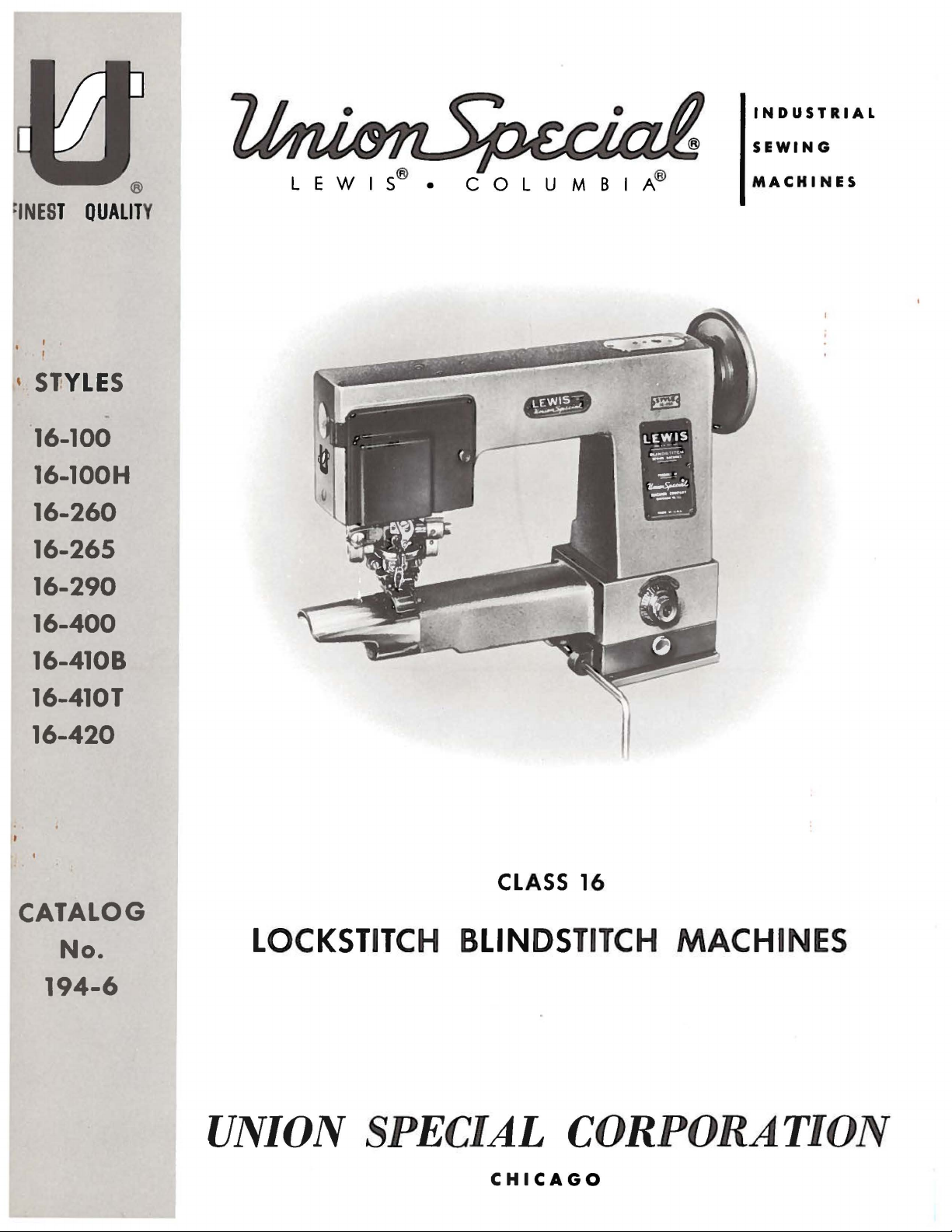
High
the
The
operating direction
Production,
Cylinder
Calibrated
Removing
16-100
Single
suits
Also
Ideal
as
trouser
machine
travels
Union
Special
is
stamped
number
Lewis
in
of
each
bearing.
to
direction,
applies
specifically
such
operator• s position
Base
Penetration
Work.
needle
and
all
used
for
for
alteration
cuffs.
will
right
Two
Machine.
Maximum
types
under
sew
to
left
Thread,
Adjustment.
machine
of
knit
felling
rooms
Machine
straight
and
machine
the
style
machine
carries
plate
is
APPLICATION
to
as rig
ht
while seated
of
the
handwheel
DESCRIPTION
Single
Non-skip
1
Lower Fee
Work
Space
for
hemming
garments.
coat
collars
or
small
produces
lockstitch.
penetrates
at
a
style
on
the
stamped
OF
CATALOG
the
styles
and
left,
at
OF
forward
the
machine.
is
away
MACHINES
Curved
to 1 Stitch.
d.
to Rig
ht
medium
Particularly
or
felling
factories.
overcast
Work
an
support
angle
front
in
the
of
from
Needle,
Knee
of
Needle
desirable
Will
stitch.
of
45°
number,
of
the
column.
main
frame
machines
and
back,
the
Lockstitch,
Overcast
Lifter
10
weight
tape
edges
handle
By
plate
to
line
which,
at
the
listed
etc
operator.
or
Straight
for
Inserting
Inches.
trouser
cuff
for knitted
and
cylindrical
removing
not
included.
of
feed.
in
this
class
left
upper
herein.
.•
are
taken
Blindstitch,
Stitch.
s,
ladies•
dresses.
bridle
work
tape.
such
spreaders,
Needle
All
and
16-100
collars
plate
16-260
and
for
4
penetrates
spreaders
16-265
linings
similar
16-290
sleeves
Machine
Minimum
travels
straighd
for
16-400
topcoats
plate.
H
included.
Single
medium
quick
3/4
inches.
Single
Single
15
Single
Needle
Single
on
overcoats
needle
weight
inserting
at
is
needle
to
sleeves
garments.
needle
of
men• s sport
cylinder
sleeve
right
lockstitch
machines.
needle
of lig
travels -right
needle
machine,
and
similar
machine for felling
suit
coats
and removal
Work
an
possible,
support
angle
of
but
15°
machine,
at
cuffs
Work
on
support
machine
or suit
fitted
diameter
to
left
without
with
and
4
penetrates
spreaders
machine
ht
and
tropical
to
similar
heavy
and
of
plate
to
not
generally
similar
medium
for
felling
end
3/4
for
weight
left
to
weight garments.
sleeve
topcoats.
sleeves
not
included.
line
of
to
16-260
and
plate
wigan
coats
cov
er
for qui
inches.
at
is
possible,
felling
materials.
and
penetrates
16-100
exceptequippedforfell
linings to
Machine
and
linings.
Needle travels left
feed.
Sewing straight
recommended
except
heavy
not
of lig
Work
an
weight
included.
or
dummy strip sleeve lining
ht
and
ck
inserting
support
angle
but
under
collars
Includes
at
Removable
sleeves
cylinder fitt
Medium
for
equipped
overcoat
medium
pl9te
of
15
not
to
generally
on
men's
removabbe
an
angle
work
at
cuf
fs
ed
with
sleeve
lockstitch wit
15°
machines.
for
felling
s,
car
weight
and
removal
not
included.
line of
recommended
suit
work
of
25
to
i
ngunder
support
on
tropic
end
diamet
to rig
ht
sle
coats
to
materials.
of
Needle
feed.
Sewin
coats
support
line
of
cov
and
hout
eve
and
coat
wor
and
feed.
al
er
er
k.
g
4
DESCRIPTION
OF
MACHINES
(Continued)
16-410
and
Needle
Sewing
16-410
slacks
removable
angle
commended
*16-420
work
angle
These
starts.
seconds
Most
fact
they
Page
B
Single
pockets
travels
straight
T
Single
and
of
15
Similar
supp~rt
of
90
machines
Use a good
at
100
of
the
are
6,
will
be
needle
in
topcoats
right
lockstitch
needle
skirts
~ork
to
feed.
on
15°
to
16-100
plate
to
line
grade
Fahrenheit.
oiling
painted
beneficial.
machine
to
machine
of
heavy
support
Sewing
machines.
included.
of
feed.
should
of
places
red.
for
and
overcoats.
left
and
without
for
materials
plate.
straight
except
to
Needle
be
oiled
straight
on
these
However,
fell:ing
penetrates
spreaders
felling
Needle
sew
printing
travels
OILING
twice
mineral
machines
reference
medium
Includes
at
is
not
bottom
producing
travels
lockstitch
press
right
daily,
before
oil
of a Saybolt
are
readily
to
and
heavyweight
removable
an
angle
recommended
to
waistband
hand
right
to
felled
left
without
felt
to
left
the
identifiable
the
oiling
wo6k
of
15
on
curtain
effect.
and
penetrates
spreaders
ink
rolls.
and
penetrates
morning
viscosity
•
diagram,
bellows
facings
support
to
line
of
15°machines.
on
trousers.
Includes
is
not
Removable
and
afternoon
of
90
to
because
Fig.
plate.
feed.
at
an
re-
at
an
125
of
the
1,
on
Please
and
to
tilt
Referring
points
marked
The
lubricated
from
Union
Point
are
lubricatedwith
be
removed
The
note
that
the
machine
to
the
·~
".
and
two
points
·~"are
with a light
Special
''B"
on
under
the
a
and
the
recommended
it
will
back
oiling
one
grease
diagram
standard
grease
speed
be
necessary
from
diagram,
marked
for
the
needle
about
part
No.
refers
wheel
replenished,
of
these
to
remove
the
sub-base
it
will
"B".
bearings
once a week.
28604
to
the
P.
cover
bearing
if
necessary.
SPEED
machines
NEEDLES
to
be
noted
over
grease.
is
head
reach
on
Tubes
that
the
the
cover,
some
there
upper
of
hook
Periodically,
1500
R.
P.M.
cylinder
of
are
main
grease
driving
the
may
the
end
oiling
two
lubrication
shaft,
be
gears.
cover
cover,
places.
and
are
ordered
which
should
*
in
Not
both
Needles
uniform
Available.
for
the
blade
Lewis
and
Class
ball
16
eye.
machines
5
are
available
in
all
the
required
sizes
Fig.
1
6
STYLES
16-4108
16-410T
16-420
Fig.
2
7
NEEDLES
(Continued)
The following
Select
sure
that
Immediately
To
sample
read:
"100
Thread
Please
16-420
16-265
accurate
tracing
Uniform
Blade
29BC-075/029
29BC-090/036
29BC-100/040
29BC-110/044
a
needle
the
eye
have
needle
needle
or
Needles,
machines
note
are
with
the
that
threaded
the
in
that
threading,
lower.
these
types
of
is
large
discard
orders
the
type
Type
in
Styles
in
it
and
sizes
Blade
Dia.
11
. 02 9
11
.
036
11
.
040
11
.
044
the
proper
enough
any
needle
promptly
number
29BD-090/
accordance
16-100,
accordance
The
diagram
two
Styles
will
suffice.
are
available:
Ball
Eye
29BD-065/025
29BD-075/029
29BD-090/036
29BD-100/040
29BD-110/044
type
to
allow
which
and
and
free
may
accurately
should
036".
THREADING
with
16-100
with
for
are
H,
the
Styles
left
threading
hand
size
for
passage
have a hooked
be
forwarded.
16-290,
upper
diagram,
16-260
machines,
the
material
of
the
filled,
A
diagram,
16-400,
and
16-265
but
Blade
Dia.
. 02 5
. 02 9
.
036
.
040"
.
044
being
thread
or
blunt
an
empty
complete
Fig.
16-410
and
Styles
is
for
11
11
11
11
or
yarn
point.
container,
order
2,
on
B,
16-260
not
pictorially
the
purpose
sewn.
used.
would
Page
16-410
Be
a
7.
T,
and
of
REMOVING
Access
of
the
arm
drive
turned
Repeat
connecting
in
same
connecting
1/4
inch
shaft,
of
line
EXCESS
to
the
(Fig.
operating
operation
rod
(D).
Fig.
the
center
up
the
PLAY
connecting
3).
Remove
rod
(B)
direction.
with
Replace
3
of
spot
screw
until
the
ADJUSTING
IN
CONNECTING
rod
adjusting
arm
cover
machine
Then,
feed
arm
loosen
elevating
cover.
plunger.
with
the
spot
RODS
screws
plate,
begins to
screw
connecting
TIMING
The
on
its
from
plunger
To
accomplish
screws
and
remove
in
operating
reaches
tinue
er
has
Now,
is
and
until
NEEDLE
needle
downward
the
center
reaches
(A,
its
to
turn
first
turn
through
tighten
bind
while
machine
rod
its hig
this
Fig.
4)
the
gear.
direction
highest
the
handwheel
reached
the
needle
the
screw
(C)
TO
THE
should
stroke,
of
the
adjustment,
in
the
until
position.
its
directionofitsarrowuntiltheneedle,
on
its
Then,
on
replace
the
downstroke,
driving
shaft,
and
is
within
gear
retighten
opening
(A)
handwheel
again
and
turns
feed
PLUNGER
be
timed
it
is
plunger
hest
point
driving
Turn
the
the
plunger
Do
after
highest
crank
approximately
(B)
on
screws
in
the
in
plunger
is
being
freely.
driving
so
that,
1/4
inch
when
of
trave~
loosen
gear
handwheel
just
not
con-
the
plung-
position.
(C)
in
when
the
main
(A).
top
the
the
(B)
the
8
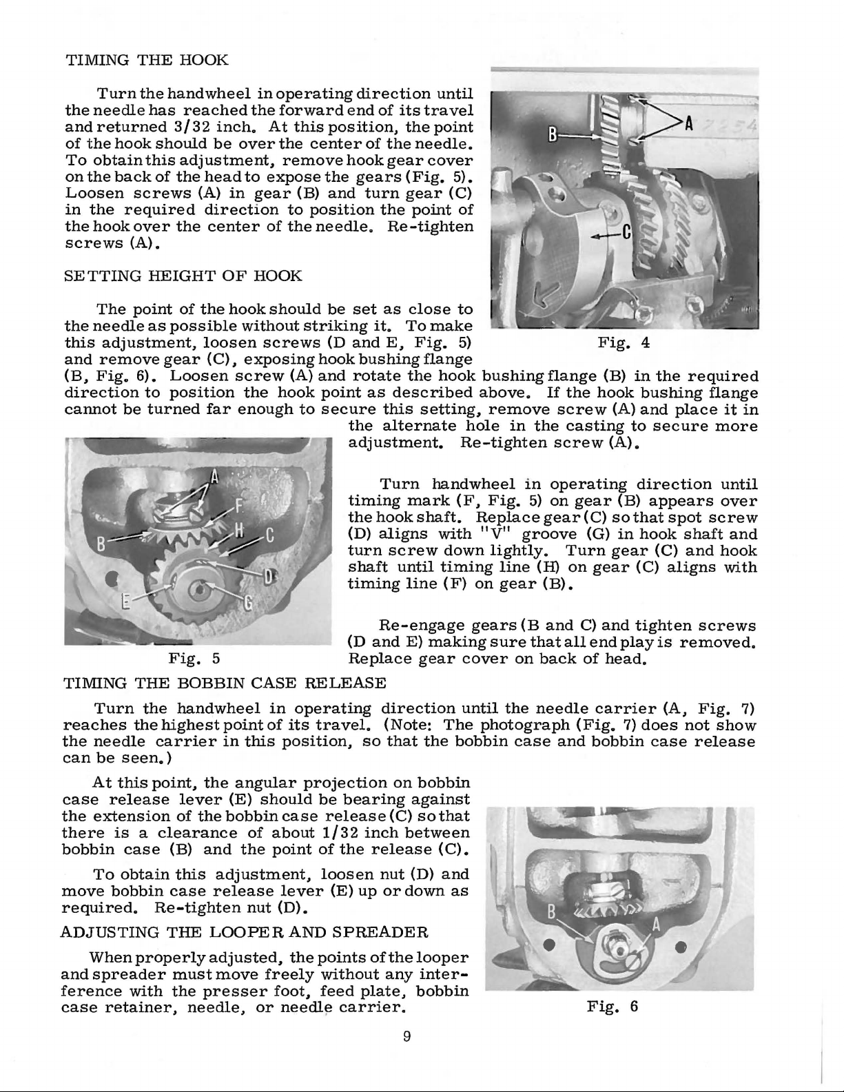
TIMING
THE
HOOK
Turn
the
needle
and
returned
of
the
hook
To
obtain
on
the
back
Loosen
in
the
required
the
hook
screws
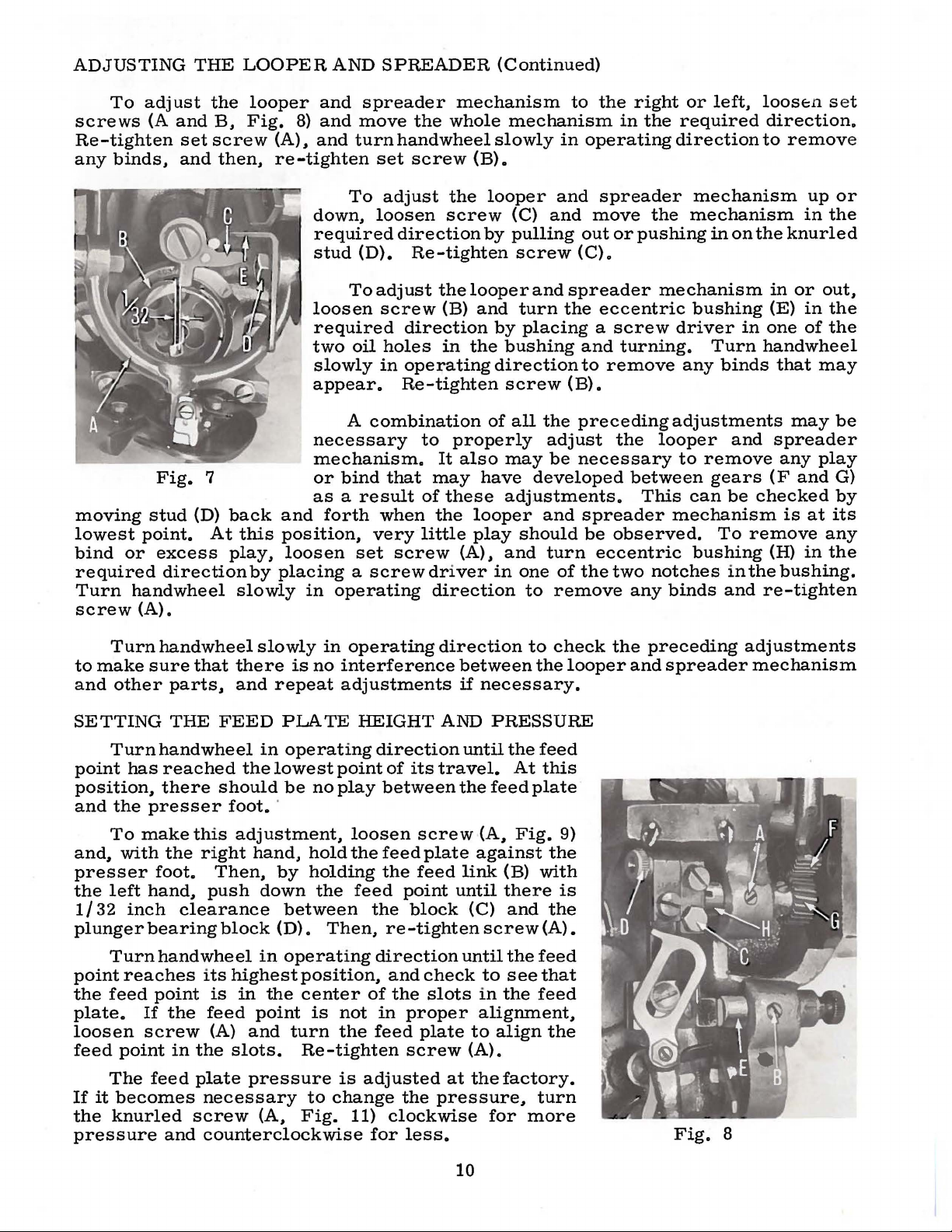
SETTING
(A).
The
the
needle
this
adjustment,
and
remove
(B.
Fig.
direction
cannot
be
the
hand
has
3/3 2 inch.
should
this
of
the
screws
over
the
HEIGHT
point
as
possible
gear
6).
Loosen
to
position
turned
wheel
reached
be
the
over
adjustment,
head
(A)
in
to
gear
direction
center
OF
HOOK
of
the
hook
without
loosen
(C).
exposing
screw
the
far
enough
in
operating
forward
At
this
the
remove
expose
(B)
to
of
the
should
screws
{A)
hook
to
end
position.
center
hook
the
and
position
needle.
be
set
striking
(D
and
hook
and
rotate
point
secure
the
adjustment.
timing
the
{D)
turn
shaft
timing
direction
of
its
the
of
the
needle.
gear
gears
turn
the
(Fig.
gear
point
Re-tighten
as
close
it.
To
E.
Fig.
bushing
the
as
described
this
alternate
Turn
mark
hook
shaft.
aligns
screw
until
line
until
travel
point
cover
5).
(C)
of
to
make
5)
flange
hook
above.
setting.
hole
Re-tighten
handwheel
(F.
Replace
with
down
timing
(F)
on
bushing
remove
in
in
Fig.
"V"
5)
groove
lightly.
line
gear
flange
If
the
screw
the
casting
screw
operating
on
gear
gear
Turn
(H)
on
{B).
Fig.
hook
{C)
{G)
gear
(B)
(A)
(A).
(B)
so
in
gear
4
in
the
bushing
and
place
to
secure
direction
appears
that
spot
hook
shaft
(C)
(C)
aligns
required
flange
it
more
until
over
screw
and
and
hook
with
in
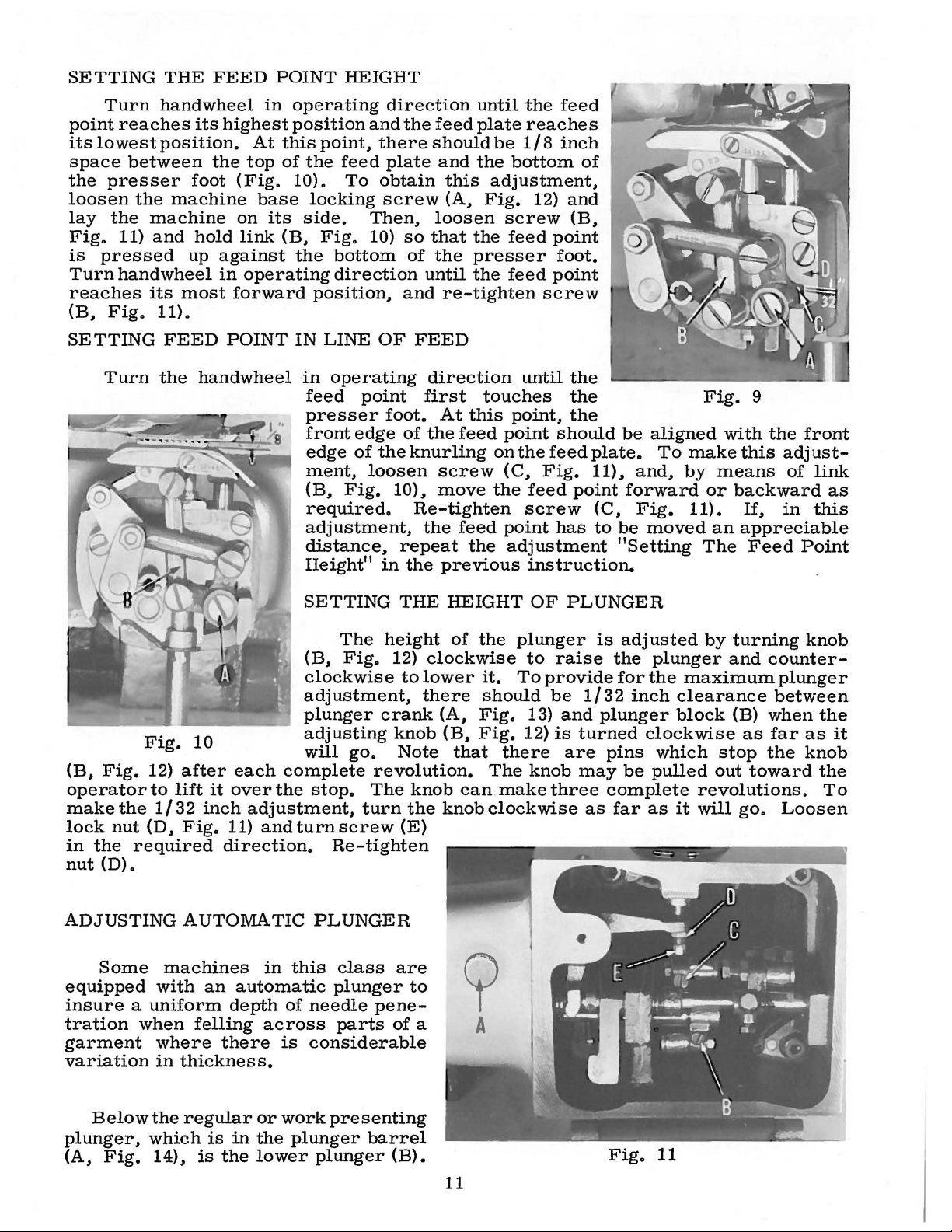
TIMING
reaches
the
needle
can
At
case
the
extension
there
bobbin
To
move
THE
Turn
the
the
be
seen.)
this
release
is a clearance
case
obtain
bobbin
required.
ADJUSTING
When
and
spreader
ference
case
properly
with
retainer.
Fig.
5
BOBBIN
handwheel
highest
carrier
point.
the
lever
of
the
(B)
and
this
adjustment.
case
release
Re-tighten
THE
LOOPER
adjusted.
must
the
move
presser
needle.
CASE
point
in
this
angular
(E)
should
bobbin
of
the
nut
or
RELEASE
in
operating
of
its
travel.
position.
projection
be
case
about
point
of
lever
(D).
AND
the
points
freely
foot,
needl~
Re-engage
(D
and
Replace
direction
(Note:
so
that
bearing
release
1/32
the
loosen
{E)
SPREADER
without
feed
{C)
inch
release
nut
up
or
of
the
any
plate.
carrier.
E)
making
gear
the
on
bobbin
against
so
between
(D)
down
looper
inter-
bobbin
cover
until
The
bobbin
that
(C).
and
as
gears
sure
(B
that
on
the
needle
photograph
case
and
all
back
and
C)
and
end
of
head.
carrier
(Fig.
bobbin
Fig.
tighten
play
7)
does
case
6
is
removed.
(A.
not
release
screws
Fig.
show
7)
9
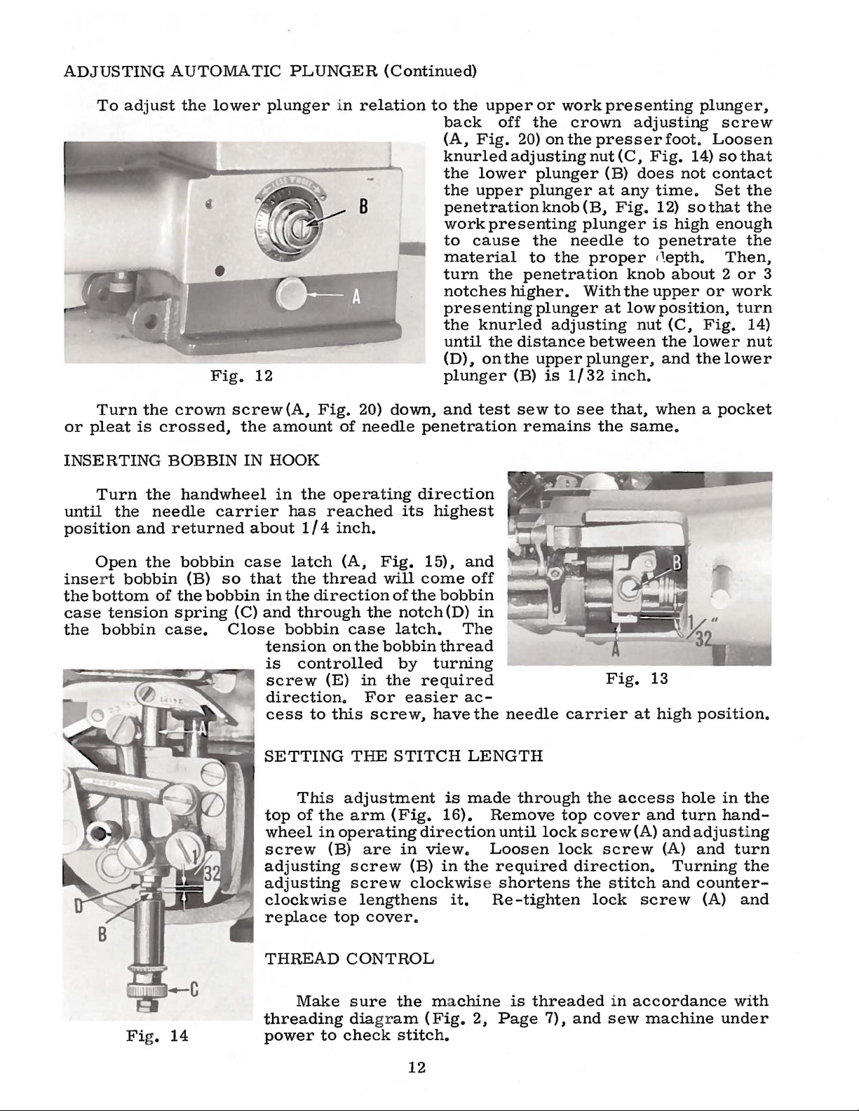
ADJUSTING
To
adjust
screws
(A
Re-tighten
any
binds.
Fig.
moving
lowest
bind
required
Turn
screw
stud
point.
or
excess
direction
handwheel
(A).
THE
and
set
and
(D)
the
B.
screw
then.
7
back
At
this
play.
slowly
LOOPER
looper
Fig.
(A).
8)
AND
and
and
and
re-tighten
down.
required
stud
loosen
required
two
slowly
appear.
necessary
mechanism.
or
bind
as a result
and
forth
position.
loosen
by
placing a screw
in
operating
SPREADER
spreader
move
turn
To
hand
set
screw
adjust
the
loosen
direction
(D).
To
Re-tighten
adjust
screw
direction
oil
holes
in
operating
Re-tighten
A
combination
that
when
very
set
screw
mechanism
whole
wheel
(B).
the
screw
the
looper
(B)
in
the
to
properly
It
also
may
of
these
the
looper
little
play
(A).
driver
direction
(Continued)
mechanism
slowly
looper
(C)
by
pulling
in
and
and
screw
and
and
turn
by
placing a screw
bushing
direction
screw
of
all
the
adjust
may
be
have
developed
adjustments.
and
should
and
turn
in
one
of
to
remove
to
the
in
operating
spreader
move
out
or
(C).
spreader
the
eccentric
and
turning.
to
remove
(B).
preceding
the
necessary
spreader
be
observed.
eccentric
the
two
right
the
or
required
direction
the
mechanism
pushing
mechanism
driver
any
adjustments
looper
to
between
This
can
mechanism
notches
any
binds
left.
loose:n
direction.
to
mechanism
in
on
the
in
bushing
Turn
binds
(E)
in
one
handwheel
that
and
spreader
remove
gears
To
bushing
be
remove
in
the
and
checked
(F
(H)
re-tighten
s et
remov
up
or
in
the
knurled
or
out.
in
the
of
the
may
may
be
any
play
and
G)
by
is
at
its
any
in
the
bushing.
e
Turn
to
make
and
sure
other
SETTING
Turn
point
has
position.
and
the
presser
To
make
and.
with
presser
the
left
hand.
1/32
plunger
inch
bearing
Turn
point
the
plate.
loosen
feed
reaches its
feed
If
screw
point
The
If
it
becomes
the
knurled
pressure
handwheel
that
parts.
THE
FEED
handwheel
reached
there
should
this
the
right
foot.
Then.
push
clearance
block
hand
wheel
point
the
is
feed
(A)
in
the
feed
plate
necessary
screw
and
counterclockwise
slowly
there
and
is
repeat
PLATE
in
operating
the
lowest
be
foot.
·
adjustment.
hand.
by
down
between
(D).
in
operating
highest
in
the
position.
center
point
and
turn
slots.
Re-tighten
pressure
to
(A.
Fig.
in
operating
no
interference
adjustments
HEIGHT
point
no
play
loosen
hold
the
holding
the
feed
Then.
of
is
not
the
is
adjusted
change
11)
for
direction
of
its
between
screw
feed
plate
the
feed
point
the
block
re-tighten
direction
and
check
the
slots
in
proper
feed
plate
screw
the
pressure.
clockwise
less.
direction
between
if
necessary.
AND
PRESSURE
until
travel.
the
feed
(A.
against
link
until
(C)
screw
until
to
in
alignment.
to
align
(A).
at
the
factory.
for
to
the
the
At
plate
Fig.
(B)
there
and
the
see
the
feed
turn
more
check
feed
this
9)
the
with
is
the
(A).
feed
that
the
the
looper
preceding
and
spreader
Fig.
adjustments
mechanism
8
10
SETTING
THE
FEED
POINT
HEIGHT
Turn
point
its
space
the
loosen
lay
Fig.
is
Turn
reaches
(B,
SETTING
reaches
lowest
between
presser
the
the
11)
pressed
hand
Fig.
Turn
handwheel
its
position.
the
foot
machine
machine
and
hold
up
against
wheel
its
most
11).
FEED
the
handwheel
in
highest
At
top
(Fig.
base
on
its
link
in
operating
forward
POINT
operating
position
this
point,
of
the
feed
10).
locking
side.
(B,
Fig.
the
bottom
direction
position,
IN
LINE
in
operating
feed
presser
front
edge
ment,
(B,
Fig.
required.
adjustment,
distance,
Height"
and
To
Then,
10)
point
edge
of
loosen
direction
the
feed
there
obtain
screw
OF
the
in
should
plate
loosen
so
that
of
the
until
and
FEED
direction
first
foot.
of
the
knurling
10).
Re-tighten
the
repeat
the
until
plate
be
and
the
this
adjustment,
(A,
Fig.
screw
the
presser
the
re-tighten
touches
At
this
feed
point
on
screw
move
previous
feed
the
(C,
the
point
the
feed
reaches
1/8
inch
bottom
12)
feed
feed
until
point,
the
feed
screw
adjustment
instruction.
of
and
(B,
point
foot.
point
screw
the
the
the
should
feed
Fig.
point
has
be
plate.
11).,
forward
(C,
to
be
"Setting
aligned
To
and,
Fig.
moved
Fig.
make
by
means
or
11).
an
The
9
with
the
this
adjust-
of
backward
If,
in
appreciable
Feed
front
link
as
this
Point
Fig.
(B,
Fig.
operator
make
lock
in
nut
ADJUSTING
equipped
insure a uniform
tration
garment
variation
the
nut
the
(D).
Some
required
when
10
12)
after
to
lift
1/32
(D,
in
inch
Fig.
AUTOMATIC
machines
with
where
an
felling
thickness.
each
it
over
adjustment,
11)
andturnscrew
direction.
in
automatic
depth
across
there
SETTING
(B,
clockwise
adjustment,
plunger
adjusting
will
complete
the
stop.
Re-tighten
PLUNGER
this
class
plunger
of
needle
parts
is
considerable
The
height
Fig.
crank
go.
revolution.
The
turn
pene-
THE
12)
clockwise
to
lower
there
knob
Note
knob
the
(E)
are
to
of
a
HEIGHT
of
the
it.
should
(A,
Fig.
(B,
Fig.
that
The
can
knob
clockwise
?
A
OF
plunger
to
To
13)
12)
there
knob
make
PLUNGER
is
raise
provide
be
1/32
and
plunger
is
turned
are
may
three
as
adjusted
the
plunger
for
the
inch
clockwise
pins
complete
be
far
which
pulled
as
by
turning
and
maximum
clearance
block
it
(B)
as
stop
out
revolutions.
will
go.
counter-
plunger
between
when
far
the
toward
Loosen
knob
the
as
it
knob
the
To
Belowthe
plunger,
(A,
Fig.
regular
which
14),
is
is
in
the
or
work
the
plunger
lower
presenting
barrel
plunger
(B).
11
Fig.
11
ADJUSTING
To
adjust
AUTOMATIC
the
lower
•
Fig.
plunger
12
PLUNGER
in
relation
8
(Continued)
to
the
back
(A,
knurled
the
the
penetrationknob(B,
work
to
material
turn
notches
presenting
the
until
(D),
plunger
upper
off
Fig.
20)
adjusting
lower
upper
presenting
cause
the
penetration
higher.
knurled
the
distance
on
the
(B)
or
work
the
crown
on
the
plunger
plunger
the
needle
to
the
plunger
adjusting
upper
is
1/32
presenting
adjusting
presser
nut ( C,
(B)
at
any
Fig.
plunger
to
proper
knob
With
the
at
low
between
plunger,
inch.
foot.
Fig.
does
time.
12)
is
high
penetrate
,l.
epth.
about 2 or
upper
position,
nut
(C,
the
and
plunger,
Loosen
14)
not
contact
Set
sothat
enough
or
Fig.
lower
the
screw
so
that
the
the
the
Then,
work
turn
14)
nut
lower
3
Turn
or
pleat
INSERTING
Turn
until
position
Open
inse
r t
the
bottom
case
the
the
is
the
the
and
the
bobbin
tension
bobbin
crown
crossed,
BOBBIN
handwheel
needle
returned
bobbin
(B)
of
the
spring
case.
screw
the
IN
carrier
about
case
so
that
bobbin
(C)
Close
(A,
Fig.
amount
HOOK
in
the
has
reached
1/4
latch
the
thread
in
the
direction
and
through
bobbin
tension
is
controlled
screw
direction.
cess
SETTING
top
wheel
screw
adjusting
adjusting
clockwise
replace
to
This
of
the
in
(E)
20)
of
needle
operating
inch.
(A,
Fig.
will
the
case
on
the
bobbin
in
the
For
this
screw,
THE
adjustment
arm
operating
(B)
are
screw
screw
lengthens
top
cover.
down,
ofthe
notch(D)
latch.
by
STITCH
(Fig.
in
and
test
penetration
direction
its
highest
15),
and
come
required
easier
direction
view.
(B)
clockwise shortens
off
bobbin
in
The
thread
turning
ac-
have
the
LENGTH
is
made
16).
in
the
it.
needle
Remove
until
Loosen
required
Re-tighten
sew
to
remains
carrier
through
top
lock
lock
see
that,
the
same.
Fig.
at
the
access
cover
screw(A)
screw
direction.
the
stitch
lock
when a pocket
13
high
position.
hole
in
and
turn
hand-
and
adjusting
(A)
and
Turning
and
counter-
screw
(A)
the
turn
the
and
Fi
g.
14
THREAD
Make
threading
power
CONTROL
sure
diagram
to
check
the
ma
(Fig.
stitch.
12
chine
2,
Page
is
threaded
7),
and
in
accordance
sew
machine
with
under
THREAD
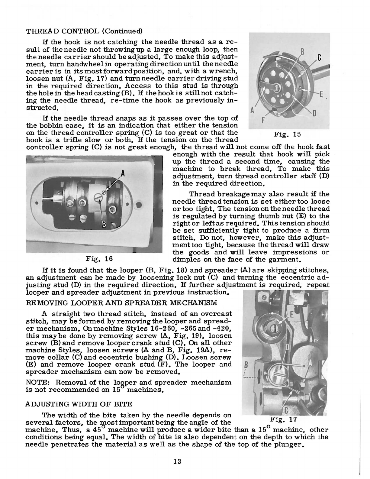
If
the
sult
of
the
the
needle
ment.
carrier
loosen
in
the
ing
structed.
the
on
hook
controller
turn
is
nut
the
required
hole
in
the
needle
If
the
bobbin
the
thread
is a trifle
CONTROL
hook
needle
carrier
in
(A.
the
needle
case,
spring
is
not
not
should
handwheelin
its
most
Fig.
direction.
head
casting
thread.
thread
it
controller
slow
(C)
(Continued)
catching
throwing
be
adjusted.
operating
forward
17)
and
turn
Access
(B).
re-time
snaps
is
an
indication
spring
or
both.
is
not
great
the
needle
up a large
direction
position.
needle
to
If
the
hook
the
hook
as
it
passes
that
(C)
is
If
the
tension
enough.
thread
enough
To
make
until
and.
with a wrench.
carrier
this
stud
is
still
as
previously
over
either
too
great
on
the
enough
up
the
machine
adjustment.
in
the
as a re-
loop.
this
adjust-
the
needle
driving
is
through
not
catch-
the
top
the
tension
or
that
the
thread
thread
with
thread
to
turn
required
then
stud
in-
of
the
will
the
result
a
second
break
thread
direction.
not
thread.
A
come
that
time.
controller
Fig.
off
hook
To
15
the
hook
will
causing
make
staff
fast
pick
the
this
(D)
If
it
is
an
adjustment
justing
looper
REMOVING
stitch.
er
this
screw
machine
move
(E)
spreader
NOTE:
is
not
stud
and
straight
A
may
mechanism.
maybe
(B)
and
Styles.
collar
and
remove
mechanism
Removal
recommended
Fig.
found
(D)
spreader
LOOPER
be
done
can
in
two
formed
On
by
remove
loosen
(C)
and
looper
that
of
16
the
be
made
the
required
adjustment
AND
thread
by
removing
machine
removing
looper
screws
eccentric
crank
can
the
lospe
on
15
looper
SPREADER
stitch.
Styles
now
machines.
by
loosening
direction.
in
screw
crank
(A
bushing
stud
be
·r
and
(B.
instead
16-260.
removed.
needle
or
is
right
be
stitch.
ment
the
dimples
Fig.
18)
lock
previous
MECHANISM
the
looper
(A.
Fig.
stud
(C).
and
B.
Fig.
(D).
(F).
The
spreader
Thread
thread
too
tight.
regulated
or
left
set
sufficiently
Do
too
tight.
goods
on
and
spreader
nut
(C)
If
further
instruction.
of
an
overcast
and
spread-
-265
and
19).
loosen
On
all
19A).
Loosen
looper
mechanism
breakage
tension
The
tension
by
turning
as
required.
not.
however.
because
and
will
the
face
and
adjustment
-420.
other
re-
screw
and
may
is
thumb
tight
the
leave
of
the
(A)
are
turning
B
,
,
,
also
set
either
on
the
needle
nut
This
tension
to
produce
make
thread
impressions
garment.
skipping
the
eccentric
is
required.
result
too
(E)
this
will
stitches.
if
the
loose
thread
to
the
should
a
firm
adjust-
draw
or
ad-
repeat
ADJUSTING
The
several
machine.
conditions
needle
penetrates
WIDTH
width
factors.
of
the
Thus. a 45°
being
equal.
the
the
OF
BITE
bite
most
machine
The
material
taken
important
by
will
width
as
the
needle
being
produce a wider
of
bite
well
as
13
the
is
the
depends
angle
also
shape
of
bite
dependent
of
on
the
than a 15°
on
the
top
the
of
Flg.
machine.
depth
the
plunger.
.
7
1
other
to
which
the
ADJUSTING
WIDTH
OF
BITE
(Continued)
to
see
over
20)
Fig.
the
to
18
thatthe
projection
hold
the
A
groove
bobbin
Foranygivenset
be
adjusted
left
by
loosening
bite
will
result~
REMOVING
FOOT
Turn
rection
est
screws
to
to
and
plunger
the
position
tighten
foot
in
until
position~
which
the
head
release
remove
To
replace
at
knee
lifter
on
the
on
the
in
the
bobbin
the
bobbin
in
position.
bymoving
screw
to
AND
REPLACING
handwheel
the
plunger
and
hold
casting.
the
pressure
foot.
the
its
lowest
and
the
frame.
two
screws
head
casting~
case
case
oftheseconditions~
the
(C).
right
edge
acts
guide
Bymovingthe
the
reverse.
thewidthof
(B.
Fig.
guide
PRESSER
in
operating
is
remove
the
presser
Press
on
foot~
position.
place
the
Replace
that
being
(F~
Fig.
retainer
in
its
the
knee
the
keep
hold
(D~
low-
lifter
Press
foot
sure
15)
Fig.
di-
two
foot
foot
the
in
and
the
fits
20)
to
Fig.
thebitemay
to
the
the
left~
19
right
a
wider
or
Check
not~
loosen
needle
guide.
in
the
in
order
to
see
screw
passes
over
Re-tighten
guide.
to
This
obtain
that
the
(F)
and
the
needle
screw
(F).
adjustment
accuracy
needle
turn
guide.
The
and
guide
(E)
handwheel
This
needle
is
especially
consistency
lines
slowly
will
should
important
of
up
exactly
in
operating
allow
now
the
ride
needle
when
penetration.
with
in
the
the
center
felling
needle.
direction
to
center
light
If
the
of
the
materials
it
until
needle
groove
does
the
Fig.
19A
14
Fig.
20
ILLUSTRATIONS
ORDERING
REPAIR
PARTS
This
of
various
actual
a
listing
required
Numbers
position
ordering
Component
ted
by
Example:
51
4115-72-4
52
4121-3
53
54
listed.
mended,
1306 L
It
catalog
sections
position
of
the
in
the
in
of
that
parts.
indenting
16-352
will
The
so
be
reason
the
has
of
in
the
parts
particular
the
first
part
Always
parts
noted
complete
of
their
Plunger
16-400,
is
been
in
in
arranged
the
mechanism
machine.
with
descriptions
that
their
view
column
the
illustration.
use
the
sub-assemblies
Bearing
16-410
Plunger
Screw
Bushing
the
above
the
sub-assembly
to
simplify
are
shown
On
the
page
part
being
are
part
Frame
--------------------------------------------------
replacement
numbers,
shown.
reference
number
which
under
Block,
B,
-----------------------------------------------
example
should
the
16-410
and
ordering
so
opposite
description
numbers
Reference
listed
can
be
description
complete,
T,
16-420
Barrel
that
of
be
the
this
ordered.
repair
that
Assembly
the
the
only,
number
in
the
furnished
for
Styles
---------------------------
plunger
part
individually
parts.
parts
illustration
and
the
and
should
second
for
of
the
16-100,
------------------------
bearing
may
be
number
merely
never
column.
repairs
main
sub-assembly.
block
is
Exploded
seen
in
will
be
of
indicate
be
used
are
16-100
is
not
not
recom-
views
their
found
pieces
the
in
indica-
H,
1
1
1
1
At
in
this
only
numbers
UNION
sidiaries
proved
and
forwarded
directed.
the
Where
Success
SPECIAL
scientific
durability
Prices
the
back
book.
part
number
the
represent
in
Repair
and
authorized
are
f.o.b.
A
charge
of
the
This
will
is
construction
the
same
the
operation
Parts
principles,
are
assured.
net
cash
shipping
is
made
book
will
facilitate
known.
IDENTIFYING
permits,
part,
USE
GENUINE
of
as
furnished
distributors.
and
and
subject
point.
to
cover
be
found a numerical
locating
PARTS
each
regardless
these
are
TERMS
to
Parcel
postage
part
REPAIR
machines
by
the
They
made
with
change
Post
of
the
illustration
is
stamped
catalog
PARTS
can
Union
are
designed
utmost
without
shimpents
and
insurance.
index
in
be
secured
Special
precision.
notice.
are
of
all
and
with
which
according
its
they
only
Corporation,
All
insured
the
parts
description
part
Maximum
number.
appear.
with
genuine
its
to
the
shipments
unless
shown
when
Part
sub-
most
otherwise
ap-
efficiency
are
15
16
MAIN
FRAME.
BUSHINGS.
COVERS.
AND
MISCELLANEOUS
PARTS
Ref.
No.
1
2
3
4
4A
5
6
7
8
9
10
11
12
13
14
15
16
17
18
19
20
*21
22
23
24
25
26
t27
t27A
28
29
30
31
32
33
34
35
36
37
38
39
40
41
42
43
44
45
46
47
48
49
50
51
52
53
54
55
56
57
58
Part
No.
478-10
16-368
39-128
18-957
125-23
666-65
18-596
432-279
61-49
41-55
61-47
22-298
61-46
89-58
478-13
16-367
16-353
CS231
21-410
18-1047
32-281
32-285
32-282
32-286
CS313
32-277
32-276
432-136
18-998
50-263
18-959
14-508
50-262
40-139
18-1030
51-26
22-C214-2
1005
14-472
48-166
1192 L
20-34
1173
1137
418-102
22-296
18-1028
21-404
4149-30
22-C214-4
21-237
79-31
22-C214-4
44-301
18-1045
22-148
1321 L
16-379
16-356
16-354
61-75
17-167
3-91
L
L
L
Description
Needle
Bushing.
Collar
Screw--------------------------------------------------------Oil
Oil
Screw--------------------------------------------------------Cover.
ThreadGuide-------------------------------------------------Thread
Head
Looper
Plug----------------------------------------------------------
Needle
Bearing.
Main
Nut-----------------------------------------------------------
Spring
Knurled
Head
Head
Head
Head
Screw---------------------------------------------------------
Cylinder
Cylinder
Cylinder
Screw---------------------------------------------------------
L
6
Cylinder
Hinge
Hinge
Sub-Base
Sub-Base------------------------------------------------------
Washer
Sub-Base
Sub-Base
SetScrew-----------------------------------------------------
Plunger
Plunger
Collar
Plunger
Screw--------------------------------------------------------Spring
Plunger
Stop
Notched
Screw---------------------------------------------------------
Locating
Plunger
Plunger
Feed
Feed
Feed
Stud.
Bearing.
on
--------------------------------------------------------
Cup
-------------------------------------------------------
Wick------------------------------------------------------
complete-----------------------------------------------
Oil
Tube
Tube
Cover
Shaft
Bearing.
on
Shaft
-------------------------------------------------------Screw-------------------------------------------------
Cover.
Cover.
Cover.
Cover.
End
End
End
Base
Bracket
Bracket
Hinge
------------------------------------------------------Locking
Locking
Sub-Base
Regulating
Regulating
Adjusting
LockNut--------------------------------------------------
--------------------------------------------------------
SetScrew-------------------------------------------------
Regulating
Pin-------------------------------------------------------
-------------------------------------------------------Regulating
Stop
Pin---------------------------------------------------
Spring
Ball
------------------------------------------------------
Pin-------------------------------------------------------
Disc
Dowel
Rocker
Rocker
Elevating
Rocker
Elevating
for
base
right
------------------------------------------
new
machines
--------------------------------------------------
--------------------------------------------------
Hinge
new
Bushing.
----------------------------------------------------
Pin
Bearing
left
machines
left
for
Styles
for
Style
for
Styles
for
Styles
Cover.
Cover.
Cover.
Hinge
Pivot
Screw--------------------------------------
Shaft
--------------------------------------------
Bracket
Latch
Latch
Locking
Crank
Bell
Set
Screw
Screw.
Knob
Plate
---------------------------------------------
Pin---------------------------------------------
Shaft
Shaft
Rocker
Shaft
Bushing--------------------------------------
and
Feed
-------------------------------------------------
--------------------------------------
------------------------------------------
Oil
Tube
----------------------------------
-------------------------------------------
--------------------------------------
----------------------------------------
16-100.
16-420
16-290.
16-260.
for
Styles
for
Styles
for
Styles
Bracket------------------------------------
----------------------------------------
Adjusting
----------------------------------------
Latch
Shaft-----:-----------------------------
Crank.
----------------------------------------
Assembly-------------------------------
Bushing
Bushing.
Shaft
Rocker
-100 H ---------------------------
-----------------------------------
-400.
-265
16-100.
16-100
16-260.
Pin--------------------------------
complete
-----------·-----------------------on
Bushing-----------------------------
-410
B.
-----------------------------
-420
H.
-265.
Screw
large----------------------------
-----------------------------
new
machines-------------------
Shaft
Oil
-410
---------------------
-400.
-290----------------
-------------------------
Tube--------------------
T--------------
-410
B.
-410 T ----
Amt.
Req.
2
1
1
2
2
2
2
1
3
1
1
1
1
1
1
1
1
1
1
1
1
1
1
1
1
1
1
1
4
1
2
1
1
1
1
1
1
1
1
1
1
1
1
1
1
1
1
1
1
1
1
1
1
1
1
4
2
2
1
1
1
1
1
NOTE:
t
*
Use
On
screw
new
No.
machines
18-1106
for
two
Styles
No.
18-959
16-260.
will
16-265
be
replaced
and
by
16-290.
one
17
No.
14-508.

15
1
3"-1
TORQ~.
17-19
£0-22
TO
ern.
lbs.
kg;_
)
18
HOOK,
LOOPER,
SPREADER
AND
NEEDLE
DRIVING
PARTS
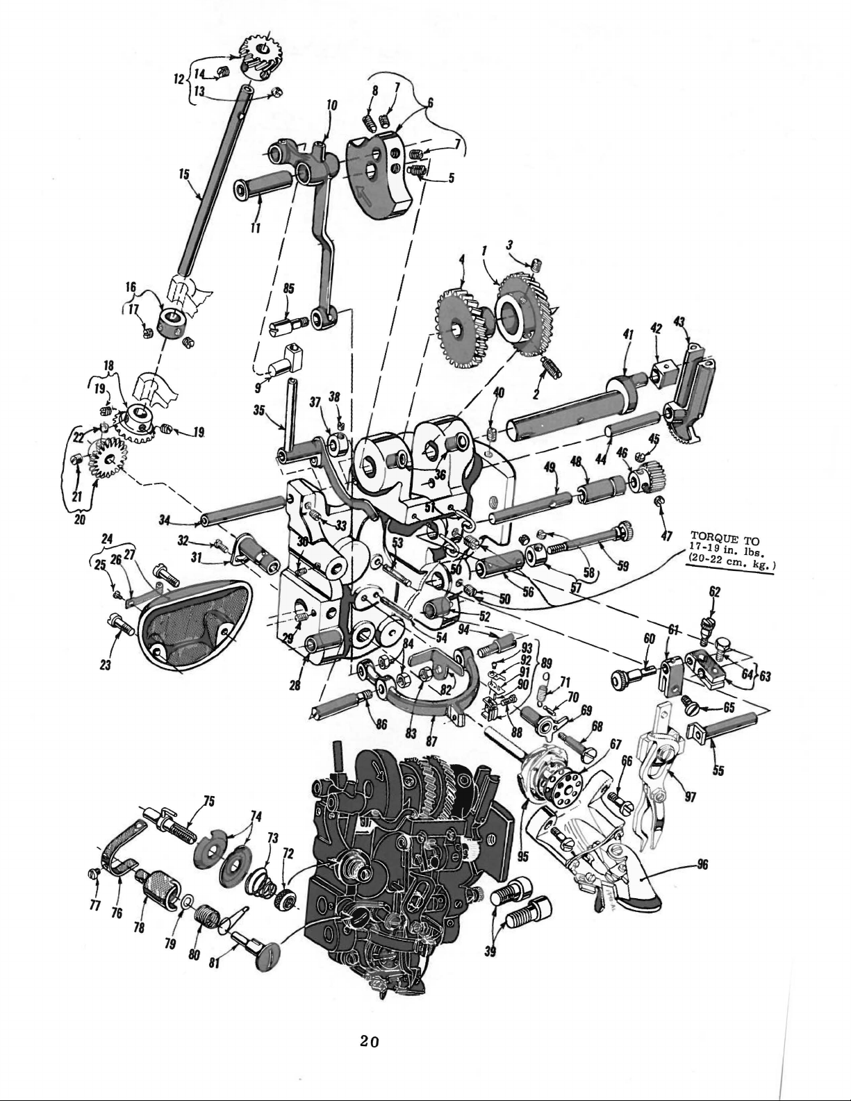
Ref.
No.
1
2
3
4
5
6
7
8
9
10
11
12
13
14
15
16
17
18
19
20
21
22
23
24
25
26
27
28
29
30
31
32
33
34
35
36
37
38
39
40
41
42
43
44
45
46
LS330
LS330
1151 L
1080
1137 L
to
97
Part
No.
1146
1146
SL
1002
1005 L
1143 L
1142 L
27-120
27-1
1144 L
1002 L
1001 L
1005 L
1003 L
1023 L
115-28
1006
46-38
1006
SL
1004
1024
1031 L
1029
1026
L
1027 L
1029
L
1028
L
1025 L
1030
L
1029
L
1031 L
1073
L
1072
AL
1075 L
1074
L
1072 L
1059
L
1081 L
416-11
1170
L
1020
L
1019
M
1018
AL
445-96
445-234
125-23
1021 L
1022
L
18-1045
1140
L
1149
L
28-2
L
L
L-1/2
L
L
L
L
Description
Hook
-290,
Hook
Drive
Drive
-400,
Gear,
-410
Gear,
for
Styles
B,
-410 T ----------------------------------
for
Style
16-100,
16-420
-100
H,
-----------------------------
-260, -265,
SpotScrew---------------------------------------------------
Set
Screw----------------------------------------------------
Head
Driven
Head
Driven
Head
Driven
Head
Driven
Head
Driven
Spot
Screw---------------------------------------------------
Needle
Set
Set
Take
-up
-290,
Take-up
Needle
-290,
Needle
Needle
Needle
Hook
Shaft
Spot
Set
HookShaft
Collar-------------------------------------------------------
Set
Hook
Shaft
Set
Gear,
Gear,
Gear,
Gear,
Gear,
Crank
Screw------------------------------------------------
for
for
for
for
for
Styles
Styles
Styles
Style
Style
16-100,
16-260,
16-290,
-100
H--------------------
-265----------------------
-410
B,
16-400----------------------------16-420-----------------------------
------------------------------------------------
Screw------------------------------------------------
Lever
-400,
Lever
Carrier
-410
Carrier
Carrier
Driving
Slide
Block,
-410
B,
Slide
-410
Block,
Connecting
B,
-410 T ---------------------------------------Connecting
Connecting
Stud
------------------------------------------
Driven
Gear
for
T,
for
Link,
Link,
Link,
Styles
-420
Styles
16-1
---------------------------16-260,
for
Styles
for
Styles
for
Styles
---------------------------------------
00,
16-100,
16-260,
16-400,
Screw-----------------------------------------------
Screw------------------------------------------------
---------------------------------------------------
Screw------------------------------------------------
Driving
Gear---------------------------------------
Screw------------------------------------------------
HookDrivenGear---------------------------------------------
Set
Screw------------------------------------------------
Spot
Screw-----------------------------------------------
Screw
HookCover,
------------------------------------------------------complete-----------------------------------------
Screw---------------------------------------------------
Thread
Hook
Needle
Set
Screw----------------------------------------------------
Clip
and
Cutter------------------------------------
Cover----------------------------------------------
Carrier
Bearing
Stud
Bushing,
left
----------------------
SetScrew---------------------------------------------------Adjustable
Screw
SpotScrew---------------------------------------------------
Take-up
Take-up
-290,
Take-up
Take-up
Oil
Cup------------------------------------------------------
Hook
Bushing,
complete,
marked
----------------------------------------------------Lever
Lever,
-410
Lever,
Lever,
Shaft------------------------------------------
complete,
B,
-410 T ---------------------------------------complete,
complete,
for
for
for
Styles
Styles
Styles
16-100,
16-260,
16-400,
''
-100
-265---------------
-420---------------
Collar------------------------------------------------------Set
Screw----------------------------------------------------
Screw
Set
Head
Slide
Looper
Looper
Looper
-------------------------------------------------------
Screw----------------------------------------------------
Main
-400,
Block
Driving
Driving
-410
Driving
Shaft
----------------------------------------------
--------------------------------------------------
B,
Sector,
Sector,
-410
Sector
T,
Shaft
for
for
-420
Styles
Styles
16-260,
16-100,
----------------------------------
-----------------------------------
-265------------------
-100
SetScrew---------------------------------------------------See
following
page
-410 T ------------
-1
00 H,
-265--------------
-100
H,
-265
---------
-420
---------
1
B'
----------------
H,
H,
-290,
Amt.
Req.
- - 1
1
1
1
1
1
1
1
1
1
1
1
2
1
1
1
1
1
1
1
1
1
1
1
1
2
1
2
1
1
1
2
1
1
1
1
1
1
1
1
1
1
1
1
1
2
1
1
2
1
1
1
1
1
1
1
19
TORQUE
17-19in.
(20-22
-
czn.
TO
lbs.
kg.
)
--
20
HOOK, LOOPER, SPREADER
AND
NEEDLE DRIVING PARTS
to
Part
No.
45
Ref.
No.
1
46 1152 L
1153 L
47
48
1136 L
16-269
1156 L
49
14-307
50 1005
51
52
53
54
*55
56
57
1181 L
1060 L
1055 L
1053 L
70-70
16-365
41363 u
58 22743
*59
60
61
62
63
64
65
66
67
68
69
70
71
72
73
18-1060
17-171
1161 L
18-1059
448-177
18-715
1158 L
1073 L
1047 L
18-719
445-251
1049L
1054 L
20-60
21-284
74 1183 L
75
76
77
1182
1188 L
1189 L
78 1186 L
79 1185 L
80 1187 L
81
82
83
84
85
86
87
68-19
1056 L
1012 L
1009 L
1008 L
1010 L
1007 L
118-23
88
89
1014 L
1432
430-37-1
90 1420 L
91
92
93
94
41-28
1016 L
1036 L
1011 L
95
96
97
L
AL
AL
Description
See
preceding
Looper
-40~
Looper
Shaft
-410B,
Shaft
page
Driven
-410
Driven
Gear,
Gear,
for
T,
Styles
-420------------------------------------for
Styles
16-100, -100
16-260,
-265------------------
H,
SpmScrew------------------------------------------------------
Looper
-290, -400, -410 B,
Looper
Shaft
Shaft
Eccentric
Eccentric
Bushing,
-410
T,
Bushing,
for
Styles
-420
-------------------------------
for
Styles
16-100,
16-260, -265
-100
LooperShaft----------------------------------------------------
SetScrew-------------------------------------------------------
Thread
Needle
Guide---------------------------------------------------
Carrier
Bearing
Stud Bushing,
right------------------------
SpringPin------------------------------------------------------
Pin--------------------------------------------------------
Stop
Sleeve---------------------------------------------------------Bushing
Collar
--------------------------------------------------------
---------------------------------------------------------
SetScrew--------------------------------------------------Knurled
Looper
Looper
Clamp
Looper
Adjusting
Crank
Head Block
Screw----------------------------------------------------
Crank,
Screw
-----------------------------------------
Stud----------------------------------------------
----------------------------------------------
complete
-----------------------------------------
Screw------------------------------------------------------
Screw---------------------------------------------------------Screw----------------------------------------------------------
Bobbin
BearingScrew
Bobbin
---------------------------------------------------------
Case
--------------------------------------------------
Release
Lever,
complete-----------------------------
SpringPin--------------------------------------------------
Spring
Tension
--------------------------------------------------------Adjusting
Nut-------------------------------------------TensionSpring-------------------------------------------------TensionDisc----------------------------------------------------
Tension
Thread
Staff,
complete
Controller
------------------------------------------
Staff
Stop--------------------------------------
Screw----------------------------------------------------------
Thread
Thread
Thread
Thread
Bobbin
Nut
Nut
Needle
Needle
Needle
-290, -410 B,
Needle
Controller
Controller
Controller
Controller
Case
Staff
Barrel--------------------------------..----
Staff
Washer----------------------------------Spring
Staff
----------------------------------------
------------------------------------------
Release---------------------------------------------
------------------------------------------------------------
-----------------------------------------------------------Carrier
Carrier
Carrier,
Carrier,
Driving
Bearing
for
Styles
-410
T,
for
Style
Stud--------------------------------------
Stud,
left---------------------------------
16-100, -100
-420
-------------------------------------
16-400
---------------------------------
H,
-260, -265,
Screw----------------------------------------------------------
Needle Clamp,
-260, -265, -290, -410 B,
Needle
Needle
Hook,
Presser
Looper
Clamp,
Pin
--------------------------------------------------------
Thread
Thread
Screw-----------------------L------------------------------
Carrier
complete
Fom,
and
complete,
complete,
Guide
Guide
Plate,
Plate,
Bearing
with Bobbin
complete
Spreader,
for
Styles
-410
for
Style
lower
upper
Stud,
Case
-See
complete
16-100, -100
T,
-420
16-400
-------------------------
-------------------------
H,
-----------------------------------
-----------------------------------
right--------------------------------
-See
Page
No.
27
Page
Nos. 31, 33, 35, 37, 39 --------
-See
Page
No.
27
------------------
-290,
H,
------------
----------------
Amt.
Req.
--
1
1
1
1
1
1
2
2
1
1
1
1
1
1
2
1
1
1
1
1
1
1
2
1
1
1
1
1
1
1
2
1
1
1
1
1
1
1
1
1
2
1
1
1
1
1
1
1
1
1
1
1
1
1
1
1
.)
*For
use
117-53 on
with
later
either
model
No.
117-49
machines
or
117-50
-See
Page
on
27,
older
model
Reference
machines,
No. 40
21
or
nm
51.
used
with No. 117-52
or

22
MAIN
SHAFT,
FEED
AND
PLUNGER
DRIVING
PARTS
Ref,
No,
1
2
3
4
5
6
7
8
9
10
11
12
13
14
15
16
17
18
19
20
21
22
23
24
25
26
27
28
29
30
31
32
33
34
35
36
37
38
39
40
41
42
43
44
45
46
47
48
49
50
51
52
53
Part
No,
1200
L
427-131
27-121
27-2
1201
L
1203
L
18-492
1005
L
1003
L
14-323
57-45
57-42
CS320-1/2
18-748
40-180
1206
L
1218
L
1209
AL
1214
L
1213
L
1020
L
1210
L
1207
L
1211
L
1208
L
1212
L
1206
L
1205
L
1215
L
1204
L
1147
L
1005
L
1009
L
448-75
1243
L
1244
L
1288
L
1291
L
1292
L
1293
L
1333
L
1294
L
1027
L
1029
L
1055
L
1283
L
1284
L
1022
L
478-11
449-32
449-33
1281
L
1272
L
21-26
1270
L
1270
L
1271
L
478-23
16-366
1295
L
61-82
Description
Gear,
Gear,
Gear,
Gear,
Gear,
MainShaft---------------------------------------------------Handwheel, 3 7/32
Handwheel,
Screw-------------------------------------------------------VVasher
Clamp
Plunger
Feed
Clamp
Feed
Feed
Feed
Nut---------------------------------------------------------Feed
Bearing
Bearing
Plunger
Plunger
Plunger
Collar
SpringPin---------------------------------------------------Spring
Collar
Ball
Feed
Feed
Nut---------------------------------------------------------Flat
Flat
-290, -400,
Flat
Knurled
Ball
Plunger
Plunger
Plunger
for
driving
for
driving
for
driving
for
driving
for
driving
Spot
Screw,
-410
Spot
Set
Set
Set
Spring--------------------------------------------------Screw----------------------------------------------------
Spot
Spot
Feed
Set
Guide
Feed
Spot
Set
Clamp
Set
Spot
Set
Set
Bearing,
Spring
Feed
Feed
Feed
Bearing,
T,
Screw,
Screw,
-410
T,
Screw,
Screw
------------------------------------------------------
Screw
Connecting
Driving
Screw
Screw
Driving
Screw
Pin------------------------------------------------
Driving
Screw
Driving
Elevating
Elevating
Screw
Screw
Driving
Screw
Screw-----------------------------------------------Screw-----------------------------------------------Differential
Differential
Rocker
Screw
Screw
------------------------------------------------------Screw
-------------------------------------------------------
------------------------------------------------------Screw
Depresser
Depresser
Pin------------------------------------------------
Spring,
Spring,
Spring,
Adjusting
Rocker
Rocker
Rocker
head,
head,
head,
head,
head,
for
-420
for
for
-420
for
on
new
------------------------------------------------
------------------------------------------------and
Plunger
-----------------------------------------------
----------------------------------------------and
-----------------------------------------------Eccentric------------------------------------
------------------------------------------------Connecting
Connecting
Eccentric
-----------------------------------------------
------------------------------------------------
and
Elevating
---------------------------------------------
Crank-----------------------------------------
------------------------------------------------
-----------------------------------------------
------------------------------------------------
------------------------------------------------
complete
Yoke,
Yoke,
short,
long,
-410
long,
Screw---------------------------------------
complete
Shaft
Shaft------------------------------------------
Shaft
for
Styles
for
Styles
for
Styles
for
Style
for
Style
Styles
--------------------------------------Styles
Styles
-------------------------------------------Styles
inch
machines, 4 11/16
Rod----------------------------------------
Crank------------------------------------Crank
B,
Bushing
Tube-------------------------------------
16-100,
16-260,
16-100,
16-260,
working
Crank
Plunger
Rod-----------------------------------
Rod---------------------------------
--------------------------------------
Crank-------------------------------
Link--------------------------------
with
washers---------------------------complete
complete
for
for
Styles
-410
T-----------------------------------
for
Style
with
washers----------------------------
16-100,
16-260,
16-290,
16-400------------------------16-420-------------------------
-100
-265-------------------------
-100
-265--------------------------
diameter------------------------
Disc,
Crank
Style
----------------------------------
Disc
with
pin------------------------
with
pin,
16-400-----------------------16-100,
16-420-------------------
-100
-265------------------
-410
H,
-290,
H,
-290,
inch
working
complete------------------
-----------------------
on
-100
H---------------B,
-410 T --------
-400,
-400,
diameter------
new
machines--------
H,
-260,
-410
-410
-265,
B,
-
B,
-
----
-----
Amt.
Req.
1
1
1
1
1
1
1
1
1
1
1
1
2
1
1
1
1
1
2
1
1
1
1
1
1
1
2
1
1
1
1
1
5
2
1
3
2
1
1
1
1
1
1
2
1
1
2
1
1
1
1
1
1
1
1
2
1
1
1
1
1
23

~
r---
1
I
I
I
I
I
\
\
\
\
I
I
I
I
I
I
I
I
I
I
I
I
I
I
:
I
-------.
41
35___,
:~
133~
~32~
L ____ _
__
.....
24

FEED
AND
PLUNGER
DRIVING
PARTS
Ref.
No,
1
2
3
4
5
6
7
8
9
10
11
12
13
14
15
16
17
18
19
20
21
22
23
24
25
26
27
28
29
30
31
32
33
34
35
36
37
38
39
40
41
42
43
44
45
46
47
48
49
50
51
51A
52
53
54
55
56
57
Part
No.
1260
L
1261
L
1262
L
1160
L
1259
AL
1248
AL
1667
L
1671
L
1677
AL
1254
L
1256
L
1309
L
1584
L
1310
L
18-533
1160
L
1669
L
1672
L
18-745
46-94
1249
L
1249
L
21-255
1311
L
1304
L
48-168
18-1027
1298
L
22-297
426-93
426-93-1
1311
L
20-98
149-22
70-33
42-14
21-19
18-125
22-9
50-138
26-93
21-230
21-281
18-791
48-165
18-416
16-366
478-23
115-139
21-403
1306
L
1279
L
667
B-20
4115-72-4
4115-73-3
4121-3
470-31
16-352
1273
L
49-36
1414
L
Description
Feed
Plate -See
Bearing
Feed
Feed
Hinge
Nut------------------------------------------------------------------
Feed
Feed
Stud----------------------------------------------------------------Bearing
Feed
Feed
Plunger -See
Plunger
Plunger
Plunger
Screw,
Nut-----------------------------------------------------------------Feed
Roll----------------------------------------------------------------Bearing
Feed
Bearing
Bearing
Plunger
Nut------------------------------------------------------------------
Plunger
Plunger
Spot
Pin------------------------------------------------------------------ 1
Automatic
Automatic
Screw,
Plunger
Plunger
Ball
Plunger
Plunger
Screw
Screw
Dowel
Plunger
-410
Plunger
Slide
Feed
Screw
Screw--------------------------------------------------------
Link------------------------------------------------------------
Point -See
Pin------------------------------------------------------------
Rocker
Elevating
Screw--------------------------------------------------------
Link,
Spring
Bearing
Screw-----------------------------------------------------------
Nut-------------------------------------------------------------Knurled
Regulator
Pressure
Regulator
Retaining
Screw
Guide
Bracket----------------------------------------------------------
Plunger,
Pressure
Pressure
Set
Bearing,
Plunger
Plunger
Bushing----------------------------------------------------------
Block----------------------------------------------------------Plate
Pin
Retaining
Spring,
Spring,
Spring,
for
slide
Elevating
Screw--------------------------------------------------------
Elevating
Stud
Screw--------------------------------------------------------
Equalizing
Frame
Crank--------------------------------------------------------
Plunger,
Plunger,
-----------------------------------------------------------
Pin
for
Styles
Regulating
Screw
Regulating
Regulating
Crank
---------------------------------------------------------------
---------------------------------------------------------------
Pin,
on
Bearing
B,
-410
Bearing
-100
H,
-290
-----------------------------------------------------------
Yoke
---------------------------------------------------------------
Page
Nos.
31,
33,
35,
37,
39
--------------------------
Page
Nos.
31, 33, 35,
Shaft,
complete--------------------------------------------------
---------------------------------------------------------
Screw----------------------------------------------------
Adjusting
Frame
Frame
complete
Rocker
-------------------------------------------------------
Spring-------------------------------------------------
Page
Nos,
heavy,
medium,
light,
Bell
Link---------------------------------------------------
Link
--------------------------------------------------------
Adjusting
Stop----------------------------------------------------
Spring
--------------------------------------------------------
lower
Spring,
Spring,
--------------------------------------------------------
complete------------------------------------------------
Spring--------------------------------------------------
new
Block,
T,
Block,
-400,
and
for
block-------------------------------------------------
Crank---------------------------------------------
Spring,
--------------------------------------------------
complete,
complete,
Nut---------------------------------------------
--------------------------------------------------
--------------------------------------------------for
for
16-100
Bell
Crank
Block
machines
-420
------------------------------------------------
and
-410
and
Stem,
with
Shaft,
31, 33, 35, 37, 39
for
Styles
for
Styles
for
Sleeve-----------------------------------------
Styles
Styles
H,
Crank,
Shaft
----------------------------------------------
complete,
complete,
Barrel
B,
Barrel
complete------------------------------------
crank---------------------------------
complete
16-100,
Styles
16-260,
Styles
for
Styles
for
Styles
16-410
16-100
-400,
small-----------------------------------
Bushing
-------------------------------------------
for
Assembly,
-410
T,
Assembly,
37,
39
--------------------------
with
crank------------------------
-----------------------------
-100
H,
16-290,
16-100,
-410
for
Styles
Styles
-420-------------------------------
-400,
-265,
16-410
16-100
B,
-410 T -----------------------
H,
-400--------------------------
B,
-410
---------------------------------
16-100,
16-260,
for
for
-420
-410 B ----------------
-410 T -------------------
-420-----------------------
B,
-410 T ----------------
H,
-400------------------
T------------------------
-100
Styles
Styles
-265,
16-100,
16-260,
------------------
H,
-400,
-290-----------
-265,
Amt.
Req.
1
1
1
1
1
2
1
1
1
2
1
1
1
1
1
1
1
1
1
1
1
1
1
1
1
2
2
1
1
1
1
1
1
2
1
1
1
1
1
1
1
1
1
1
1
2
1
1
1
1
1
3
1
3
2
1
1
1
1
1
1
1
2
25

26

ROTARY
HOOKS,
LOOPER AND SPREADER ASSEMBLIES
Ref.
No.
1
2
3
4
5
6
7
8
9
10
11
12
13
14
15
16
17
18
19
20
21
22
23
24
25
26
27
28
29
30
31
32
33
34
35
36
37
38
39
40
41
42
43
44
45
46
47
48
49
50
51
Part
No.
1040 A-1 L
1036 L
1035 L
1034
AL
1041
AL
1046 L
1043 L
18-912
1037 L
1039 L
1040
A-2
L
1036 L
1035 L
AL
1034
411-6
21-245
1046 L
18-912
1039 L
1037 L
409-25-1
1036 L
1035 L
1034
AL
411-5
1046 L
1043 L
18-912
13-22
1039 L
437-4
1160 L
37-4
17-104
36-14
1180 L
1179 L
1170 L
1166 L
117-52
437-5
1160 L
37-5
17-104
36-23
1180 L
1179 L
1170 L
916 L
125-21
117-53
Description
Hook,
Hook,
Hook,
Looper
complete,
-100
H,
-290, -400,
Screw
Needle
Hook
----------------------------------------------and
------------------------------------------------
Bobbin
Tension
Tension
Clamp
Hook
Screw
-265
Screw
Gib-------~------------------------------------
-----------------------------------------------
complete,
---------------------------------------------------
-----------------------------------------------
Needle
Hook
------------------------------------------------
Bobbin
Tension
Tension
Clamp
Screw
Hook
-----------------------------------------------
Gib---------------------------------------------
complete
Screw
-----------------------------------------------
Needle and
Hook
------------------------------------------------
Bobbin
Tension
Tension
Clamp
Hook Gib
Screw
-----------------------------------------------
and
-100
H,
-290,
-------------------------------------------------
Nut
Looper
with
Case
bobbin
-410
Thread
Guard------------------------------
-----------------------------------------
case,
B,
for
-410 T ----------------------
Screw-----------------------------------Spring
-----------------------------------
Screw-------------------------------------
with
and
Thread
C~se
----------------------------------------Spring
Screw
bobbin
Guard------------------------------
case,
for
-----------------------------------
-----------------------------------
Screw-------------------------------------
with
bobbin
Thread
case,
for
Guard------------------------------
Case------------------------------------------
Screw-----------------------------------Spring
-----------------------------------
Screw-------------------------------------
--------------------------------------------
Spreader,
-400,
complete,
-410 B,
for
-410
Spreader--------------------------------------
Styles
Styles
Style 16-420
Styles
T,
16-100,
-420
-----------------
Stud------------------------------------------------Looper
Screw
---------------------------------------------------
----------------------------------------------
Roll----------------------------------------------------Screw,
-410
Looper
-290,
Looper
-400,
Looper
-265
for
T,
Staff
-400,
Staff
-410
and
Styles
-420
Spreader,
16-100,
-100
H,
-290,
-400, -410 B,
-------------------------------------------
Bearing
-410
Bearing,
B,
B,
-410
Cap,
T,
-410
for
-420
for
T,
Styles
complete,
Styles
16-100,
-420------------------------16-100,
-100
-----------------------------for
Styles
16-260,
---------------------------------------------------
Nut-------------------------------------------------Looper
Spreader
---------------~---------------------
Stud------------------------------------------------Looper
Screw
---------------------------------------------------
----------------------------------------------
Roll----------------------------------------------------Screw,
Screw,
Looper
Looper
for
for
Staff
Staff
Styles
Styles
Bearing
Bearing,
16-260,
16-260,
Cap,
for
-265-----------------------------
-265----------------------------for
Styles
Styles
16-260,
16-260,
-265
16-100,
16-260,
-----------
-100
H,
H,
-290,
-265
-----------
---------------
Amt.
Req.
1
3
1
1
1
1
1
1
1
2
1
3
1
1
1
1
1
1
2
1
1
3
1
1
1
1
1
1
1
2
1
2
1
1
1
1
1
2
1
1
1
2
1
1
1
1
1
1
1
1
1
27

28

WORK
SUPPORT
PLATES
AND
ACCESSORIES
Ref.
No.
1
2
Part
No.
4-138
LS398
3 LS299
4
5
6
7
8
9
10
11
12
13
14
15
16
4-136
FP505
1160 L
75-133
18-330
22-301
45-422
22652
F-12
61248 H
531
71-86
4129-18
22508
*17 660-168
18
19
20 1500
21
22
23
24
25
26
27
413 D
660-240
L
1047 L
21207 B
L
1405
21201
614
77
M
61377
y
22878
Description
Work
Pivot
-420
Nut,
Work
Support
Screw,
-------------------------------------------------
for
Support
Plate,
for
Styles
Plate,
for
Styles
16-100
for
Styles
16-100
H,
-400,
Styles
16-420
H,
-400,
-410
16-100
-----------------
B,
H,
-410 T -----------------------------------------------
Adjusting
-410
Nut,
for
Edge
Guide,
Screw,
Feed
Plate
Lever
Clamp Screw
Collar
Screw
Knee
Knee
Press
Press
Screw
Knee
Oil
Press
Can
Thread
Wood
Screw
Bobbin
Screwdriver,
Double
Screwdriver,
Bobbin
Pulley
T,
for
Screw,
-420
Styles
Style
Lowering
for
Styles
16-100
H,
-400,
-----------------------------------------
for
16-100
Style
16-290
H,
-400,
16-290
-410
--------------------------
-------------------------------
Pin
-------------------------------
B,
-------------------------------------------------
--------------------------------------
------------------------------------------------
--------------------------------------------
Rod
----------------------------------------
Plate,
complete
----------------------------
-------------------------------------------Pad
----------------------------------------
-----------------------------------------------
Tweezers
---------------------------------------
--------------------------------------------
-----------------------------------------------End
Wrench
Winder,
small
large
------------------------------------
-------------------------------------
------------------------------------
complete
-------------------------------
-------------------------------------------
Set
Screw
-----------------------------------
-410
-410
-400,
-410
B,
T,
-410
T,
-410
-420
-410
B,
-420
B,
T,
--
--
Amt.
Reg.
1
2
2
1
1
1
1
2
1
1
1
1
2
1
1
1
1
1
1
4
1
1
1
1
1
1
1
* Not
furnished
with
machine,
available
as
29
extra
send
and
charge
item.


PRESSER
FEET,
FEED
PLATES, FEED POINTS, PLUNGERS
Ref.
~
1
2
3
4
5
6
7
8
9
10
11
12
13
14
:.~14A
15
16
17
18
19
20
21
22
23
24
25
26
Part
No.
1353 L
23-322
24-285
1340
AL
1340 L
1075 L
18-281
1346 L
1348
L-1/4
1058 L
1057 L
1351 L
1349 L
1353 L
26-139
23-322
24-285
1340
SAL
1340 SL
1075 L
18-281
1346 L
1348
L-1/4
1058 L
1057 L
1351 L
1349 L
Description
Standard
Alternate
Alternate
Combination
Plunger
Feed
Feed
Presser
Plunger
Plunger
FeedPoint------------------------------------------------------------FeedPlate------------------------------------------------------------Presser
---------------------------------------------------------------
Point------------------------------------------------------------Plate-------------------------------------------------------------
Foot,
Presser
Screw------------------------------------------------------------Screw-------------------------------------------------------------
Needle Guard
Needle
Screw------------------------------------------------------------Bobbin
Screw-------------------------------------------------------------
Edge Guide
Presser
Screw------------------------------------------------------------Screw-------------------------------------------------------------
Needle
Needle
Screw------------------------------------------------------------Bobbin
Screw-------------------------------------------------------------
Edge Guide
Guide------------------------------------------------------Case
Combination
---------------------------------------------------------------
---------------------------------------------------------------
Foot,
Guard-----------------------------------------------------Guide-------------------------------------------------------
Case
Combination
for
Style 16-100
complete-------------------------------------------------
Foot,
main
section-----------------------------------------
------------------------------------------------------
Retainer-----------------------------------------------
-------------------------------------------------------for
Style 16-100
complete-------------------------------------------------
Foot,
main
section-----------------------------------------
Retainer-----------------------------------------------
-------------------------------------------------------for
Style 16-100
for
Medium Weight
for
Light Weight
for
Heavy Weight
Material
Material
Material
Amt.
Req.
1
1
1
1
1
1
1
1
1
2
1
1
1
1
1
1
1
1
1
1
1
1
1
2
1
1
1
27
28
29
30
31
32
33
34
35
36
37
38
39
40
41
42
43
44
45
46
47
48
49
50
51
52
53
54
55
56
57
*
Alternate
1352 L
23-322
24-285
1339 SAL
1339 SL
1075 L
18-281
1346 L
1348
L-1/4
1058 L
1057 L
1351 L
1349 L
Alternate
26-121
23-322
24-285
1490
AL
1036 L
1778 L
1491 L
1493 L
1490 L
1075 L
18-281
1346 L
1348
L-1/4
1058 L
1057 L
1492 L
1351 L
1349 L
Combination
Plunger
FeedPoint------------------------------------------------------------Feed
Presser
Combination
Plunger
FeedPoint------------------------------------------------------------Feed
Presser
for
---------------------------------------------------------------
Plate-------------------------------------------------------------
Foot,
Presser
Screw------------------------------------------------------------Screw-------------------------------------------------------------
Needle
Needle
Screw-------------------------------------------------------------
Bobbin
Screw-------------------------------------------------------------
Edge Guide
for
---------------------------------------------------------------
Plate-------------------------------------------------------------
Foot,
Screw------------------------------------------------------------RetainingSpring---------------------------------------------------Crown------------------------------------------------------------Adjusting
Presser
Screw------------------------------------------------------------Screw-------------------------------------------------------------
Needle Guard
Needle
Screw------------------------------------------------------------Bobbin
Crown
Screw-------------------------------------------------------------
Edge Guide
Sewing
complete-------------------------------------------------
Foot,
main
section-----------------------------------------
Guard
Guide-------------------------------------------------------
Case
Style 16-100
Guide------------------------------------------------------Case
Bearing
Fine
------------------------------------------------------
Retainer-----------------------------------------------
-------------------------------------------------------for
Light Weight
complete-------------------------------------------------
Screw----------------------------------------------------
Foot,
main
section-----------------------------------------
------------------------------------------------------
Retainer-----------------------------------------------
Screw-----------------------------------------------
--------------------------------------------------------
Material
on a
Raw
Material
Edge.
with Crown
Presser
Foot
1
1
1
1
1
1
1
1
1
2
1
1
1
1
1
1
1
1
1
1
1
1
1
1
1
1
2
1
1
1
1
31
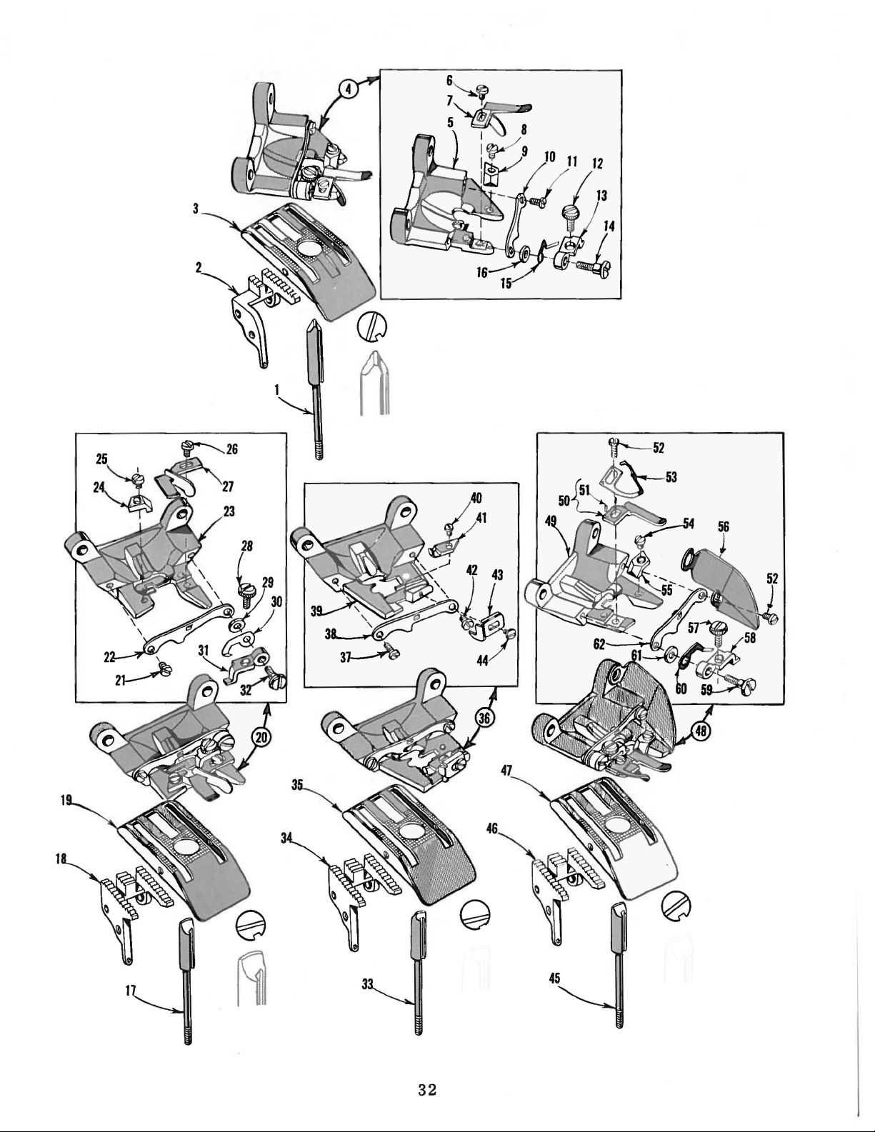
32
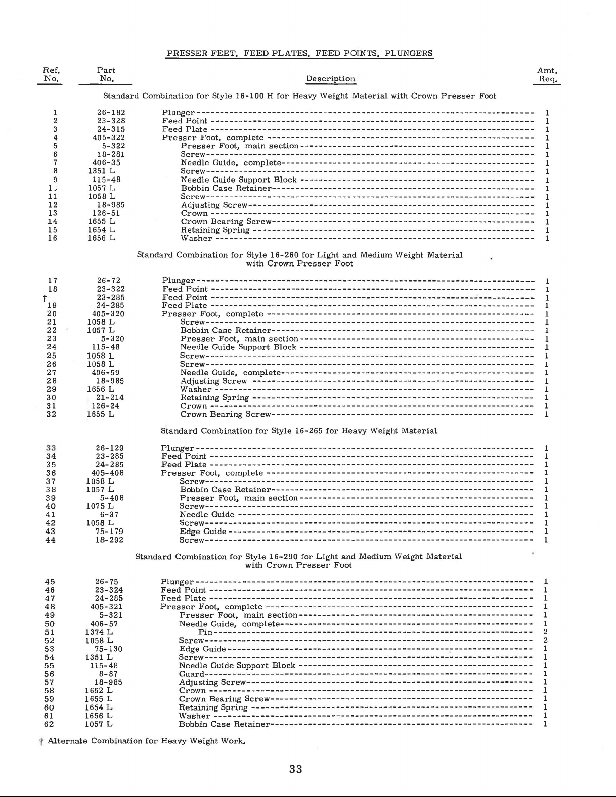
Ref,
No,
1
2
3
4
5
6
7
8
9
L
11
12
13
14
15
16
17
18
t
19
20
21
22
23
24
25
26
27
28
29
30
31
32
33
34
35
36
37
38
39
40
41
42
43
44
45
46
47
48
49
50
51
52
53
54
55
56
57
58
59
60
61
62
t
Alternate
Part
No,
Standard
26-182
23-328
24-315
405-322
5-322
18-281
406-35
1351
115-48
1057
1058 L
18-985
126-51
1655
1654 L
1656 L
26-72
23-322
23-285
24-285
405-320
1058 L
1057 L
5-320
115-48
1058 L
1058 L
406-59
18-985
1656 L
21-214
126-24
1655 L
26-129
23-285
24-285
405-408
1058 L
1057 L
5-408
1075 L
6-37
1058 L
75-179
18-292
26-75
23-324
24-285
405-321
5-321
406-57
1374 L
1058
75-130
1351
115-48
8-87
18-985
1652
1655 L
1654 L
1656 L
1057 L
Comb i
L
L
L
L
L
L
PRESSER
Combination
Plunger-----------------------------------------------------------------------Feed
Point
Feed
Plate
Presser
Presser
Screw---------------------------------------------------------------------Needle Guide,
Screw---------------------------------------------------------------------Needle Guide Support
Bobbin
Screw---------------------------------------------------------------------Adjusting
Crown--------------------------------------------------------------------Crown
Retaining
Washer--------------------------------------------------------------------
Standard Combination
Plunger-----------------------------------------------------------------------Feed
Point
Feed
Point
Feed
Plate
Presser
Screw----------------------------------------------------------------------
Bobbin
Presser
Needle Guide
Screw---------------------------------------------------------------------Screw---------------------------------------------------------------------Needle Guide,
Adjusting
Washer-------------------------------------------------------------------Retaining Spring
Crown---------------------------------------------------------------------
Crown
Standard
Plunger------------------------------------------------------------------------
Feed
Point---------------------------------------------------------------------
Feed
Plate---------------------------------------------------------------------
Presser
Screw----------------------------------------------------------------------
Bobbin
Presser
Screw---------------------------------------------------------------------Needle
Screw----------------------------------------------------------------------
Edge
Screw----------------------------------------------------------------------
Standard
Combination
Plunger-----------------------------------------------------------------------Feed
Point
Feed
Plate
Presser
Presser
Needle Guide,
Screw----------------------------------------------------------------------
Edge
Screw------------------------------------------------------------------Needle Guide
Guard---------------------------------------------------------------------Adjusting
Crown---------------------------------------------------------------------
Crown
Retaining
Washer
Bobbin
nation
for Heavy Weight Work.
FEET,
for
Style 16-100 H
FEED
PLATES,
for
Heavy Weight
FEED
Descriptio
POINTS, PLUNGERS
n
Material
with Crown
---------------------------------------------------------------------
---------------------------------------------------------------------
Foot,
complete
Foot,
---------------------------------------------------------
main
section--------------------------------------------------
complete------------------------------------------------------
Block--------------------------------------------------
Case
Retainer--------------------------------------------------------
Screw-------------------------------------------------------------
Bearing
Screw--------------------------------------------------------
Spring
------------------------------------------------------------
for
Style 16-260
with Crown
for
Light
Presser
and Medium Weight
Foot
Material
---------------------------------------------------------------------
---------------------------------------------------------------------
---------------------------------------------------------------------
Foot,
complete
Case
Retainer--------------------------------------------------------
Foot,
---------------------------------------------------------
main
Support Block
section--------------------------------------------------
--------------------------------------------------
complete------------------------------------------------------
Screw
------------------------------------------------------------
Bearing
Combination
Foot,
complete
Case
Retainer--------------------------------------------------------
Foot,
main
-------------------
Screw--------------------------------------------------------
for
Style 16-265
---------------------------------------------------------
section--------------------------------------------------
-
----------------------------------------
for
Heavy Weight
Material
Guide---------------------------------------------------------------
Guide-----------------------------------------------------------------
for
Style
16-290
with Crown
for
Light and Medium Weight
Presser
Foot
Material
---------------------------------------------------------------------
---------------------------------------------------------------------
Foot,
complete
Foot,
---------------------------------------------------------
main
section--------------------------------------------------
complete------------------------------------------------------
Pin--------------------------------------------------------------------
Guide-----------------------------------------------------------------
Support
Block
--------------------------------------------------
Screw-------------------------------------------------------------
Bearing
Screw--------------------------------------------------------
Spring------------------------------------------------------------
--------------------------
Case
Retainer--------------------------------------------------------
-
-----------------------------------------
Presser
Foot
Amt.
Req.
1
1
1
1
1
1
1
1
1
1
1
1
1
1
1
1
1
1
1
1
1
1
1
1
1
1
1
1
1
1
1
1
1
1
1
1
1
1
1
1
1
1
1
1
1
1
1
1
1
1
1
2
2
1
-
--
1
1
1
1
1
1
1
1
1
33
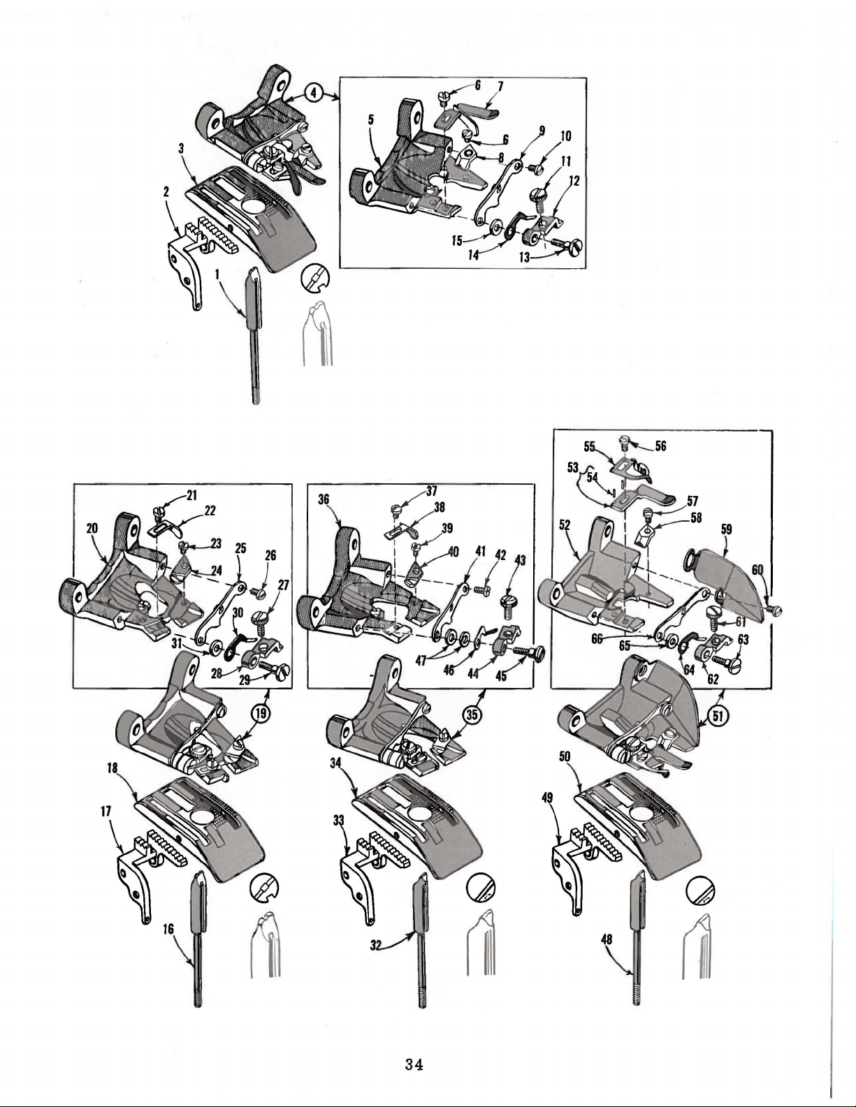
34
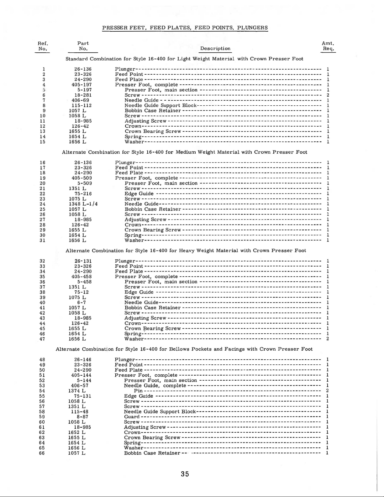
PRESSER
FEET,
FEED
PLATES,
FEED
POINTS, PLUNGERS
Ref.
No.
1
2
3
4
6
7
8
9
10
11
12
13
14
15
16
17
18
19
20
21
22
23
24
25
26
27
28
29
30
31
32
33
34
35
36
37
38
39
40
41
42
43
44
45
46
47
48
49
50
51
52
53
54
55
56
57
58
59
60
61
62
63
64
65
66
Standard
26-136
23-326
24-290
405-197
18-281
406-69
115-112
1057 L
1058 L
18-985
126-42
1655 L
1654 L
1656 L
Alternate
26-136
23-326
24-290
405-509
1351 L
75-216
1075 L
1348
1057 L
1058 L
18-985
126-42
1655 L
1654 L
1656 L
Alternate
26-131
23-326
24-290
405-458
1351 L
75-12
1075 L
1057 L
1058 L
18-985
126-42
1655 L
1654 L
1656 L
Alternate
26-146
23-326
24-290
405-144
406-57
1374 L
75-131
1058 L
1351 L
115-48
1058 L
18-985
1652 L
1655 L
1654 L
1656 L
1057 L
Part
No.
Combination
5-197
Combination
5-509
L-1/4
Combination
5-458
6-7
Combinat
5-144
8-87
Description
for
Style 16-400
Plunger---------------------------------------------------------------Feed
Point-------------------------------------------------------------
Feed
Plate-------------------------------------------------------------
Presser
Plunger---------------------------------------------------------------Feed
Feed
Presser
Plunger---------------------------------------------------------------Feed
Feed
Presser
ion
for
Plunger---------------------------------------------------------------FeedPoint------------------------------------------------------------Feed
Presser
Foot,
Presser
Screw
Needle
Needle
Bobbin
Screw-------------------------------------------------------------Adjusting
Crown-------------------------------------------------------------Crown
Spring-------------------------------------------------------------Washer-------------------------------------------------------------
for
Point------------------------------------------------------------Plate-------------------------------------------------------------
Presser
Screw --------------------------------------------------
Edge
Screw--------------------------------------------------------------
Needle
Bobbin
Screw-------------------------------------------------------------Adjusting
Crown-------------------------------------------------------------Crown
Spring-------------------------------------------------------------Washer-------------------------------------------------------------
for
Point------------------------------------------------------------Plate-------------------------------------------------------------
Presser
Screw--------------------------------------------------------------
Edge Guide
Screw--------------------------------------------------------------
Needle
Bobbin
Screw--------------------------------------------------------------
Adjusting
Crown--------------------------------------------------------------
~;~i~;-~:~:~:~:~:~================================================
Washer-------------------------------------------------------------
Style 16-400
Plate-------------------------------------------------------------
Presser
Needle
Edge
Screw-------------------------------------------------------------Screw-------------------------------------------------------------Needle
Guard-------------------------------------------------------------Screw--------------------------------------------------------------
Adjusting
Crown--------------------------------------------------------------
Crown
Spring-------------------------------------------------------------Washer-------------------------------------------------------------
Bobbin
Foot,
-------------------------------------------------------------Guide------------------------------------------------------Guide
Case
Bearing
Style 16-400
Foot,
Foot,
Guide
Guide-------------------------------------------------------Case
Bearing
Style
Foot,
Foot,
Guide-------------------------------------------------------Case
Foot,
Foot,
Guide,
Pin-------------------------------------------------------------
Guide---------------------------------------------------------
Guide
Bearing
Case
for
Light
Weight
complete-------------------------------------------------
main
section------------------------------------------
Support
Retainer------------------------------------------------
Screw
complete-------------------------------------------------
---------------------------------------------------------
Retainer------------------------------------------------
Screw
16-400
complete-------------------------------------------------
---------------------------------------------------------
Retainer------------------------------------------------
Screw-----------------------------------------------------
for
complete-------------------------------------------------
complete----------------------------------------------
Support
Screw-----------------------------------------------------
Retainer--· ·--------------------------------------------
Block-------------------------------------------
-----------------------------------------------------
Screw------------------------------------------------
for
Medium Weight
main
section
-----------------------------------------------------
Screw------------------------------------------------
for
Heavy Weight
main
section
Bellows
main
Screw------------------------------------------------
Pockets
section------------------------------------------
Block-------------------------------------------
Material
Material
---
---------------------------------------
Material
------------------------------------------
and
with Crown
with Crown
with Crown
Facings
Presser
Presser
with Crown
Presser
Presser
Foot
Foot
------------
Foot
Foot
Amt.
Req.
1
1
1
1
1
2
1
1
1
1
1
1
1
1
1
1
1
1
1
1
1
1
1
1
1
1
1
1
1
1
1
1
1
1
1
1
1
1
1
1
1
1
1
1
~
2
1
1
1
1
1
1
2
1
1
1
1
1
1
1
1
1
1
1
1
35
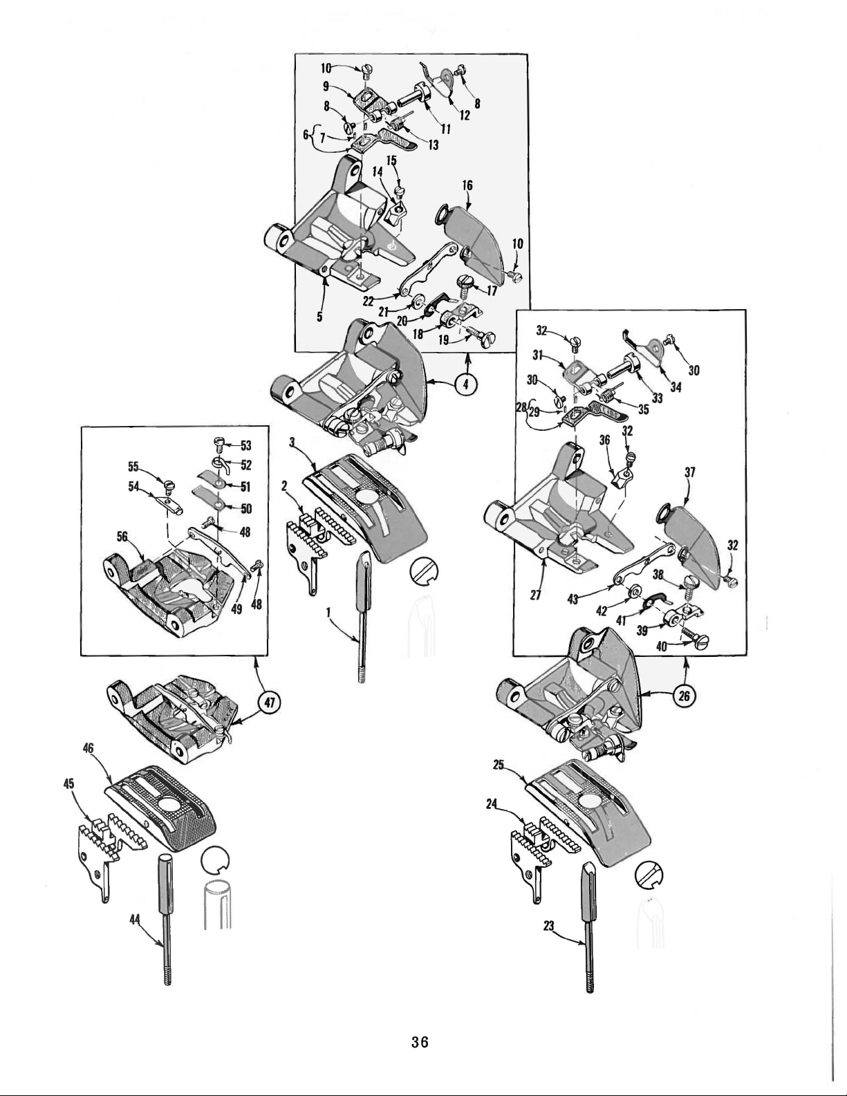
36
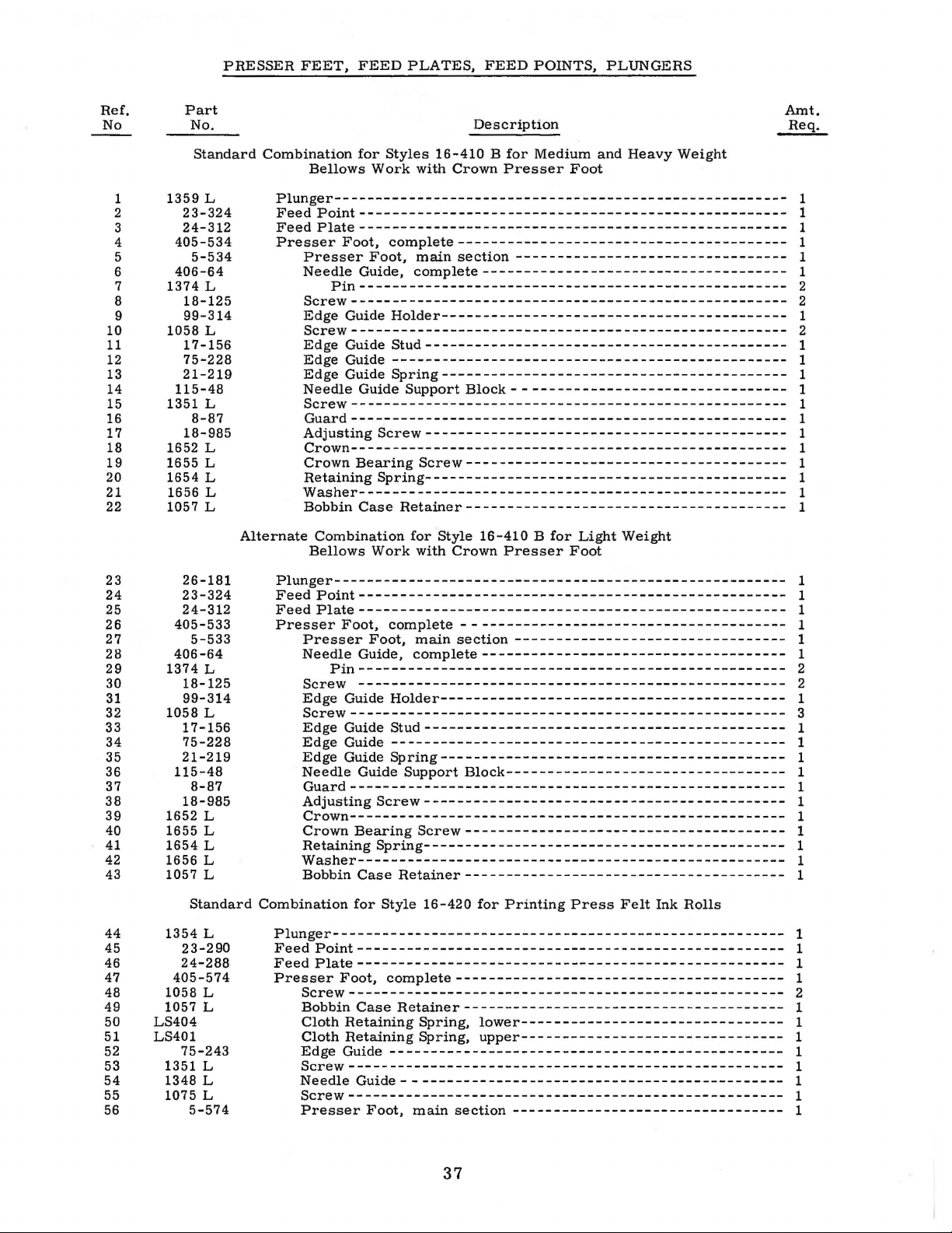
PRESSER
FEET,
FEED
PLATES,
FEED
POINTS,
PLUNGERS
Ref.
No
1
2
3
4
5
6
7
8
9
10
11
12
13
14
15
16
17
18
19
20
21
22
Part
No.
Standard
1359
23-324
24-312
405-534
5-534
406-64
1374
18-125
99-314
1058
17-156
75-228
21-219
115-48
1351
8-87
18-985
1652
1655
1654
1656
1057
L
L
L
L
L
L
L
L
L
Description
Combination
Alternate
Bellows
Plunger------------------------------------------------------Feed
Feed
Presser
Presser
Needle
Screw----------------------------------------------------Edge
Screw----------------------------------------------------Edge
Edge
Edge
Needle
Screw----------------------------------------------------Guard----------------------------------------------------Adjusting
Crown----------------------------------------------------Crown
Retaining
Washer----------------------------------------------------
Bobbin
Bellows
for
Styles
Work
Point---------------------------------------------------Plate----------------------------------------------------
Foot,
Pin----------------------------------------------------
Combination
complete----------------------------------------
Foot,
Guide,
Guide
Guide
Guide
Guide
Guide
Screw--------------------------------------------
Bearing
Spring--------------------------------------------
Case
Work
16-410 B for
with
Crown
main
section
complete
Holder-----------------------------------------Stud--------------------------------------------
------------------------------------------------
Spring------------------------------------------
Support
Screw---------------------------------------
Retainer---------------------------------------
for
with
-------------------------------------
Block---------------------------------
Style
16-410 B for
Crown
Medium
Presser
---------------------------------
Presser
Foot
Light
Foot
and
Heavy
Weight
Weight
Amt.
Req.
1
1
1
1
1
1
2
2
1
2
1
1
1
1
1
1
1
1
1
1
1
1
23
24
25
26
27
28
29
30
31
32
33
34
35
36
37
38
39
40
41
42
43
44
45
46
47
48
49
50
51
52
53
54
55
56
26-181
23-324
24-312
405-533
406-64
1374
18-125
99-314
1058
17-156
75-228
21-219
115-48
18-985
1652
1655
1654
1656
1057
1354
23-290
24-288
405-574
1058
1057
LS404
LS401
75-243
1351
1348
1075
5-533
L
L
8-87
L
L
L
L
L
Standard
L
L
L
L
L
L
5-574
Plunger------------------------------------------------------Feed
Point---------------------------------------------------FeedPlate---------------------------------------------------Presser
Combination
Plunger------------------------------------------------------FeedPoint---------------------------------------------------FeedPlate---------------------------------------------------Presser
Foot,
Presser
Needle
Pin----------------------------------------------------
Screw
Edge
Screw----------------------------------------------------Edge
Edge
Edge
Needle
Guard----------------------------------------------------Adjusting
Crown----------------------------------------------------Crown
Retaining
Washer---------------------------------------------------Bobbin
Foot,
Screw----------------------------------------------------Bobbin
Cloth
Cloth
Edge
Screw----------------------------------------------------Needle
Screw----------------------------------------------------Presser
complete
Foot,
Guide,
----------------------------------------------------
Guide
Holder------------------------------------------
Guide
Guide
Guide
Guide
Stud
------------------------------------------------
Spring------------------------------------------
Guide
Support
Screw--------------------------------------------
Bearing
Spring--------------------------------------------
Case
Retainer---------------------------------------
for
Style
complete
Case
Retaining
Retaining
Retainer---------------------------------------
------------------------------------------------
Guide
- -
Foot,
main
---------------------------------------
main
section
complete-------------------------------------
--------------------------------------------
Block----------------------------------
Screw---------------------------------------
16-420
----------------------------------------
Spring,
Spring,
-------------------------------------------section
---------------------------------
for
Printing
lower--------------------------------
upper--------------------------------
---------------------------------
Press
Felt
Ink
Rolls
1
1
1
1
1
1
2
2
1
3
1
1
1
1
1
1
1
1
1
1
1
1
1
1
1
2
1
1
1
1
1
1
1
1
37
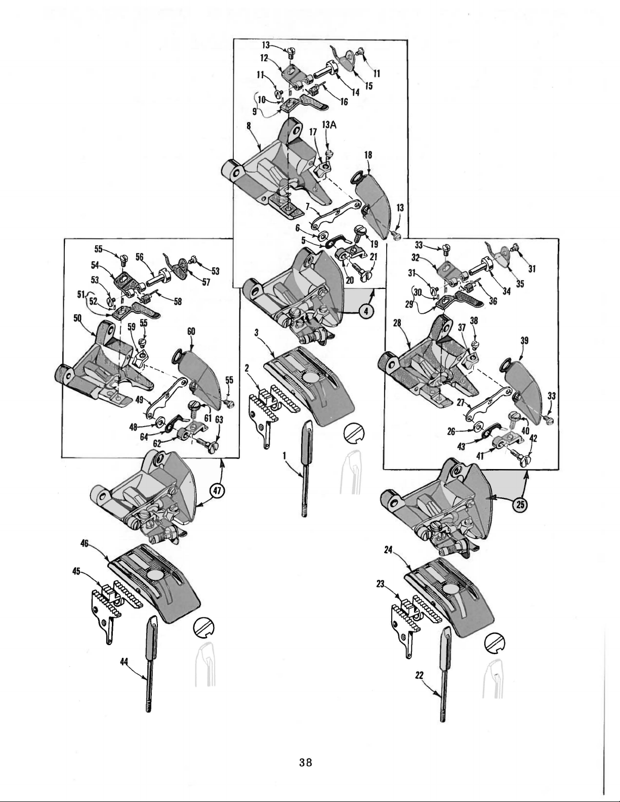
38
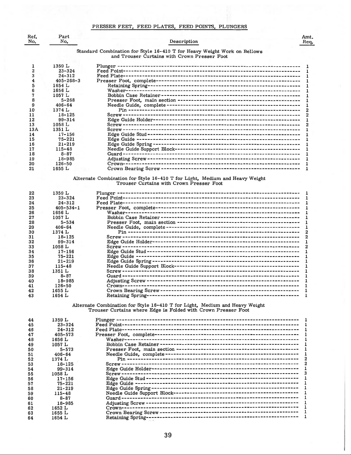
PRESSER
FEET,
FEED PLATES, FEED POINTS, PLUNGERS
Ref,
No.
1
2
3
4
5
6
7
8
9
10
11
12
13
13A
14
15
16
17
18
19
20
21
22
23
24
25
26
27
28
29
30
31
32
33
34
35
36
37
38
39
40
41
42
43
Part
No,
1359
L
23-324
24-312
405-268-3
L
1654
1656 L
1057 L
5-268
406-64
1374 L
18-125
99-314
1058 L
1351 L
17-156
75-221
21-219
115-48
8-87
18-985
126-50
1655 L
L
1359
23-324
24-312
405-534-1
L
1656
1057 L
5-534
406-64
1374 L
18-125
99-314
1058 L
17-156
75-221
21-219
115-48
L
1351
8-87
18-985
126-50
1655 L
1654 L
Standard Combination
and
Plunger
FeedPoint----------------------------------------------------------------FeedPlate----------------------------------------------------------------Presser
RetainingSpring-------------------------------------------------------Washer---------------------------------------------------------------Bobbin
Presser
Needle
Screw-----------------------------------------------------------------
Edge Guide
Screw----------------------------------------------------------------Screw-----------------------------------------------------------------
Edge Guide
Edge Guide
Edge Guide
Needle Guide
Guard-----------------------------------------------------------------
Adjusting
Crown-----------------------------------------------------------------
Crown
Alternate
Combination
Trouser
Plunger
FeedPoint-----------------------------------------------------------------
FeedPlate----------------------------------------------------------------Presser
Washer---------------------------------------------------------------Bobbin
Presser
Needle
Screw-----------------------------------------------------------------
Edge Guide
Screw-----------------------------------------------------------------
Edge Guide
Edge Guide
Edge Guide
Needle Guide
Screw----------------------------------------------------------------Guard----------------------------------------------------------------Adjusting
Crown----------------------------------------------------------------Crown
Retaining
Alternate
Combination
Trouser
Curtains
Description
for
Trouser
Style 16-410 T
Curtains
for
Heavy Weight Work on Bellows
with Crown
Presser
Foot
-------------------------------------------------------------------
Foot,
complete-----------------------------------------------------
Case
Retainer---------------------------------------------------
Foot,
main
Guide,
Pin
---------------------------------------------------------------
section---------------------------------------------
complete-------------------------------------------------
Holder------------------------------------------------------
Stud--------------------------------------------------------
-----------------------------------------------------------Spring------------------------------------------------------
Support
Block----------------------------------------------
Screw--------------------------------------------------------
Bearing
Screw---------------------------------------------------
for
Style 16-410 T
Curtains
for Light, Medium and Heavy Weight
with Crown
Presser
Foot
-------------------------------------------------------------------
Foot,
complete-----------------------------------------------------
Case
Retainer---------------------------------------------------
Foot,
main
Guide,
section
complete-------------------------------------------------
---------------------------------------------
Pin---------------------------------------------------------------
Holder-----------------------------------------------------Stud--------------------------------------------------------
-----------------------------------------------------------Spring------------------------------------------------------
Support
Block----------------------------------------------
Screw--------------------------------------------------------
Bearing
Screw---------------------------------------------------
Spring--------------------------------------------------------
for
Style 16-410 T
where
Edge
for
is
Light, Medium and Heavy Weight
Folded with Crown
Presser
Foot
Amt.
Req,
1
1
1
1
1
1
1
1
1
2
2
1
2
1
1
1
1
1
1
1
1
1
1
1
1
1
1
1
1
1
2
2
1
2
1
1
1
1
1
1
1
1
1
1
44
45
46
47
48
49
50
51
52
53
54
55
56
57
58
59
60
61
62
63
64
1359
23-324
24-312
405-573
1656
105'7 L
5-573
406-64
1374 L
18-125
99-314
1058 L
17-156
75-221
21-219
115-48
8-87
18-985
1652
1655 L
1654 L
L
Plunger------------------------------------------------------------------FeedPoint----------------------------------------------------------------FeedPlate-----------------------------------------------------------------
L
Presser
Foot,
complete-----------------------------------------------------
Washer----------------------------------------------------------------
Case
Bobbin
Presser
Needle
Pin
Screw----------------------------------------------------------------Edge Guide
Retainer-------------~-------------------------------------
Foot,
main
Guide,
section---------------------------------------------
complete-------------------------------------------------
--------------------------------------------------------------Holder------------------------------------------------------
Screw----------------------------------------------------------------Edge Guide
Edge Guide
Edge Guide
Needle Guide
Stud--------------------------------------------------------
-----------------------------------------------------------Spring------------------------------------------------------
Support
Block---------------------------------------------Guard----------------------------------------------------------------Adjusting
L
Crown----------------------------------------------------------------Crown
Retaining
Screw--------------------------------------------------------
Bearing
Screw---------------------------------------------------
Spring--~-----------------------------------------------------
39
1
1
1
1
1
1
1
1
2
2
1
3
1
1
1
1
1
1
1
1
1
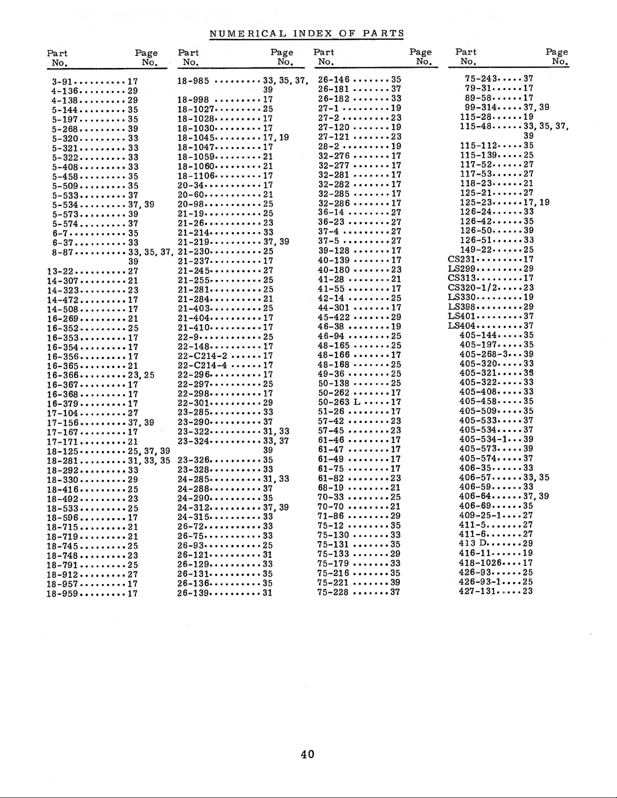
NUMERICAL
INDEX
OF
PARTS
Part
No,
3-91
..........
4-136
.........
4-138
•••••••••
5-144
•••••••••
5-197
•••••••••
5-268
•••••••••
5-320
.........
5-321
•••••••••
5-322
.........
5-408
•••••••••
5-458·········35
5-509
•••••••••
5-533
.........
5-534
.........
5-573
•••••••••
5-574
•••••••••
6-7
•••••••••••
6-37
••••••••••
8-87
••••••••••
13-22
••••••••••
14-307
14-323
14-472
14-508
16-269
16-352·········25
16-353
16-354·········17
16-356
16-365·····
16-366
16-367
16-368
16-379·········17
17-104
17-156
17-167·········17
17-171
18-125
18-281
18-292
18-330
18-416
18-492
18-533
18-596
18-715
18-719
18-745
18-748
18-791
18-912
18-957
18-959
•••••••••
•••••••••
•••••••••
•••••••••
.........
••••••••
.........
.........
.........
•••••••••
•••••••••
.........
.........
.........
•••••••••
•••••••••
•••••••••
•••••••••
•••••••••
•••••••••
•••••••••
•••••••••
•••••••••
•••••••••
.........
•••••••••
•••••••••
.........
.........
Page
No.
17
29 39
29
35
35
39
33
33
33
33
35
37
37,39
39
37
35
33
33, 35, 37,
39
27
21
23
17
17
21
·17
17
..
··21
23,25
17
17
27
37,39
21
25,
37,39
31,
33, 35
33
29
25
23
25
17
21
21
25
23
25
27
17
17
Part
No.
18-985
18-998
18-1027·
18-1028·
18-1030·
18-1045
18-1047·
18-1059·
18-1060·
18-1106·········17
20-34···········17
20-60···········21
20-98···········25
21-19·
21-26·
21-214·
21-219·
21-230·
21-237········
21-245·
21-255·
21-281·
21-284·
21-403·
21-404
21-410··········17
22-9·
22-148··········17
22-C214-2
22-C214-4······17
22-296·
22-297
22-298·
22-301··········29
23-285··········33
23-290··
23-322··········31,33
23-324·····
23-326
23-328·
24-285·
24-288·
24-290·
24-312
24-315·
26-72···········33
26-75·
26-93·
26-121·
26-129
26-131·
26-136··········35
26-139
.........
·········17
••••••••
•••••••
•••••••
.........
•••••••
........
••••••••
••••••••••
••••••••••
•••••••••
•••••••••
•••••••••
•••••••••
•••••••••
•••••••••
•••••••••
•••••••••
.........
•••••••••••
.........
..........
•••••••••
..
••••••••••
•••••••••
•••••••••
•••••••••
•••••••••
••••••••••
•••••••••
••••••••••
••••••••••
.........
••••••••••
•••••••••
..........
..
......
······37
..
···33,37
Page
No.
33,35,37,
25
·17
·17
17,19
·17
21
21
25
23
33
37,
39
25
17
27
25
25
21
25
·17
25
17
17
25
17
39
35
33
31,
33
37
35
37,
39
33
33
25
31
33
35
31
Part
No.
26-146
26-181
26-182
27-1
27-2
27-120
27-121·······23
28-2
32-276
32-277
32-281·······17
32-282
32-285
32-286·······17
36-14
36-23
37-4
37-5
39-128
40-139
40-180
41-28
41-55
42-14
44-301
45-422
46-38
46-94
48-165
48-166 • .. • ..
48-168·······25
49-36
50-138
50-262
50-263 L ·····17
51-26
57-42
57-45
61-46
61-47
61-49
61-75
61-82
68-19
70-33
70-70
71-86
75-12
75-130
75-131
75-133
75-179
7
75-221
75-228
5-216
•••••••
•••••••
•••••••
••••••••
•••••••••
•••••••
••••••••
.......
••••••
·······17
·······17
••••••••
••••••••
•••••••••
•••••••••
••••••
·······17
•••••••
••••••••
.......
••••••••
••••••
•••••••
········19
••••••••
·······25
........
·······25
••••••
········17
........
········23
........
........
•••••••
•••••••
••••••••
••••••••
••••••••
••••••••
••••••••
········35
•••••••
•••••••
.......
•••••••
•••••••
.......
.......
35
37
33
·19
23
19
·19
17
·17
27
27
27
27
·17
23
21
·17
25
·17
29
25
·17
25
·17
23
17
17
·17
·17
23
21
25
21
29
33
35
29
33
35
39
37
Page
No.
Part
No.
75-243
79-31
89-58
99-314·····37,39
115-28·
115-48
115-112·
115-139
117-52·
117-53
118-23·
125-21·
125-23·
126-24
126-42······35
126-50
126-51······33
149-22······25
CS231·
LS299.
CS313
CS320-1/2·····23
LS330·
LS398·········29
LS401.
LS404
405-144
405-197
405-268-3···39
405-320
405-321
405-322·····33
405-408·
405-458·····35
405-509·····35
405-533·····37
405-534·
405-534-1···39
405-573·····39
405-574·····37
406-35······33
406-57
406-59
406-64
406-69
409-25-1····27
411-5
411-6
413
416-11·
418-1026····17
426-93······25
426-93-1
427-131 ...
•••••
.....
.....
•••••
••••••
••
.....
•••••
••••••
••••
••••
.....
••••••
••••••
• • • • •
• • •
•••••
.........
••••••••
• • •
•••••
•••••••••
•••••
•••••
•••••
•••••
••••
••••
••••••
••••••
••••••
••••••
.......
•••••••
D
•••••••
••••
••••
••
·17
·17
··35
·21
·27
·17
·19
..
37
19
33,
35, 37,
39
25
27
27
17,
33
39
29
17
19
37
37
35
35
33
3S
33
37
33,35
33
37,39
35
27
27
29
25
23
Page
No,
19
40
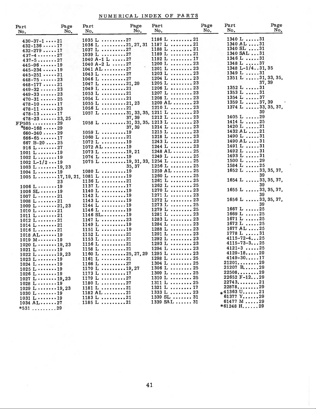
NUMERICAL
INDEX
OF
PARTS
Part
No.
430-37-1
432-136
432-279
4::17-4
437-5
445-96
445-234
445-251
448-75
448-177
449-32
449-33
470-31
478-10
478-11
478-13
478-23
FP505
*660-168
660-240
666-65
667
916L
••••
••••
•••••
•••••••
•••••••
••••••
•••••
•••••
••••••
•••••
••••••
••••••
••••••
•••••
••••••
......
••••••
•••••••••
•••••
•••••
······17
B-20
••••
•••••••
1001 L •••••••
1002 L •••••••
1002
L-1/2
1003 L •••••••
1004 L •••••••
1005 L •••••••
1006 L ·······19
1006
SL
• • • • • • 19
1007 L ·······21
1008 L
1009
•••••••
L • • • • • • •
1010 L ·······21
lOll
L
•••••••
1012 L •••
• •
1014L·······21
1016 L •••••••
1018
AL
1019
• • • • •
M·· • ····19
1020 L ·······19,23
1021 L ·······19
1022 L •••••••
1023 L ·······19
1024 L
·······19
1025 L ·······19
1026
L • • • • • • •
1027
L •
••
• • •
1028 L • • • • • • •
1029
L •
•• • ••
1030
L • • • • • • •
1031 L •••
1034AL
*531
• • •
••••••
......•..
••
-17
-17
·19
••
·19
·19.
·19,
·19
21
17
27
27
19
21
23
21
23
21
21,
21
21
19,23
19
19
19
27
29
Page
No.
19
23
25
23
17
23,
25
29
29
29
25
27
19
19
19,
23
19
17,19,
23
23
21
23
23
Part
No.
1035
L
1036
L
1037
L
1039
L
1040
A-1
1040
A-2
1041
AL
1043
L
1046
L
1047
L
1049
L
1053 L •••••••••
1054
L
1055
L
1056
L
1057
L
1058
L
1059
L
1060
L
1072
L
1072
AL
1073
L
1074 L •••••••••
1075
L
1080
L
21,
1081
L
1136
L
1137
L
1140
L
1142
L
1143
L
1144
L
1146
L
114 6 SL
1147
L
1149
L
1151
L
1152
L
1153
L
1156
L
1158
L
1160
L
1161 L •••••••••
1166
L
1170 L •••••••••
1173
L
1179
L
1180
L
1181 L
1182
AL
1183
L
1185
L
.•..••••.
.••••••••
..••.•...
.•..•..•.
•••••
L
•••••
L
••••••••
.•••••...
.......•.
.........
.........
......•..
........
.........
•••••••••
•••••••••
.•.•.•.•
•..••...•
.........
••••••••
.•.......
•••••••••
.........
..•....•.
.........
...•.....
.......•.
...•.••••
.•.••.•••
•..•.•.••
.•.•.••••
•••••••••
.•.••.•••
..•.•••••
•.•.•••.•
..••••••.
.•.••••.•
.••••••••
•••••••••
•••••••••
.•...••.•
•.•••••••
......•••
•.•••••••
..••.••••
••••••••
•••••••••
..•••••••
35,
33,
29
Part
No.
1186
1187
1188
1189
1192
1200
1201 L
1203
1204
1205
1206
1207
1208
1209
1210
1211 L
1212
1213
1214
1215
1218 L
1243
1244
1248
1249 L
1254
1256
1259
1260
1261 L
1262
1270
1271
1272
1273
1279
1281 L
1283
1284
1288 L
1291 L
1292
1293
1294 L
1295
Page
No.
27
21,
27,31
27
27
27
27
27
27
27
21,
29
21
21
21
.
21,
23
21
31,
33,
37, 39
31, 33, 35,
37,
39
• 19
21
19
19
19,
21
19
19,
31,
35,
37
19
19
21
17
19
19
19
19
19
19
23
19
19
21
21
21
21
25,
27.
21 1298 L
27
19,
17
27
27
21
21
21
21
27
1304
1306 L ••••••••
1309
1310
1311
1321 L
1333
1339
1339
L
L
L
L
L
L
L
L
L
L
L
L
AL
L
L
L
L
L
L
L
AL
L
L
AL
L
L
L
L
L
L
L
L
L
L
L
L
L
L
L
L
L
SL
S!\L
........
.......•
........
......••
••••••••
.•....•.
.•......
........
...•....
.•...•.•
•.••••••
••••••••
........
•••••••
•••...••
•..••••.
.....•..
.•••••••
....•.•.
..•••..•
..•.•..•
........
........
•.•••••
...•...•
.••.••..
.••..••.
•••••••
....••..
........
...••..•
.•..••••
........
.•••..••
•••..•••
..•.••••
.•.••••.
..•.•.•.
.••.•...
.••...•.
...•••.•
.•••.•••
..••••..
..••.••.
•..••••.
.•.•••••
••••••••
..••••..
•..••••.
...••..•
..••••••
..••.••.
.••..•.
••••••
21
21
21
21
17
23
23
23
23
23
23
23
23
23
23
23
23
2 3
23
23
23
23
23
25
25
25
25
25
25
25
25
23
23
2 3
2 5
25
23
23
23
23
23
23
23
23
23
25
25
25
25
25
25
17
23
31
31
Page
No.
Part
No.
1340 L ...••
1340
AL
1340
SL
1340
SAL
1346L
1348 L
1348
1349L
.•.•.
•••••
L-1/4
•••••
1351 L •••••
1352 L
1353 L
1354 L
1359 L
1374 L
1405 L
1414 L
1420
L
•••••
.....
•••••
•••••
•••••
.....
•••••
•••••
1432AL
1490L
1490
1491 L
1492
1493L
1500
1584
1652 L
1654 L
1655 L
AL
L
L
L
•••••
•••••
•••••
.....
..•••
..•..
•••••
•••••
•••••
1656 L .....
1667 L
1669 L
1671 L
1672 L
1677
1778 L
..••.
•••••
.••••
.•.••
AL
•••••
4115-72-4
4115-73-3
4121-3
4129-18
4149-30
21201.
.••••
•••••
•••••
•••••••
21207 B ••••••
22508
••••••••
22652
22878
*41363
F-12
22743
••••••••
••••••••
u
61377 Y
......
••••••
61477 M •••••
*61248 H ......
••••
••••
•••
••
••••
••••
••••
•••
•••
•••
Page
No.
31
31
31
31
31
37
31,35
31
31, 33,
37,
39
31
31
37
37. 39
33,
35, 37,
39
29
25
21
21
31
31
31
31
31
29
25
33,35,37,
39
33,
35, 37,
39
33,35,37,
39
33, 35,
39
25
25
25
25
25
31
25
25
25
29
17
29
29
29
29
21
29
21
29
29
29
35,
37,
41


lbals
Descrtpllon
KITS:
Floor
Mechanics Tool Kit includes
10-13, 15-20, 22, 23.
48,
57,
Traveling Mechanics Tool Kit same
Nos
. 7, 43, 44, 49-56 ..
ALLEN
WRENCHES:
Screwdriver
Sizes
~32",
Set
Standard 'L' shape Allen Wrenches .......
Set
Metric
Allen
Cluster ... . . .
BAGS:
Union
Special Tool Pouch
BRASS
4 X
Yl
e" ............ .
BRUSH:
Cleaning
BUCKLE:
Union
Special metal belt buckle .. .
CLAMP:
C-Ciamp6
CUTTER:
de
cutters 5". . . . . . . . . . . . . . . . . . . . . . . . . . . . . .
Si
EMBLEMS:
TIC
emblem
FILES:
Round 8" . . . . . . . . . . . . . . . . . . . . . . ....... . . .
FlatS" ...
Handles
Diamond file
FLASHLIGHT
Pocket flashlight with clip ..........
GAUGES:
Feeler
or
Looper
Gauges set
%
.".%2".o/,e",%2",~",
Synchronizing gauge
shown) .. .
4
W gauge for flatbed machines {not shown)
Needle
height gauge
Spreader hei
and 57900 machines (not shown)
GRINDER
Handee grinder kit . . . . . . . . . . . . .
HAMMER
4 oz.
ball peen hammer . . . . . . . . . . . . . • . . _ . . .
MAGNET:
Pocket magnet
PLIERS:
Slip
joint pliers 6". . . . . . . . . . . . . . . . . . .. . . .... .
Needle
nose pliers 6" (serrated jaws) .....
Needle
nose pliers 6" (smooth jaw) . . ... . .....
Plastic grips
Snap ring pliers . . . . . . . . ... .
Grooved pliers HL-14P
PUNCH:
Center
punch 4" . .
Drift
punch . . . . . . . . . . . . . . . . . . . . . . . . . . .
SANDING
Emery
cloth (not shown) . . . . . . .
Crocus cloth (not shown)
Roll emery cord (not shown)
&
liauges
TIC
27,
58, 72, 73 ...
handle and 4 Allen Bits
W'.
%2
'L' shape Allen Wrenches ... ....... . .
ROD:
28, 30, 33, 35, 36, 37-42,
...
. .....
.....
...
".
~e
"
.
..
· · · · · · · · · · · · · · · · · · ·
.........
...
...................
........
brush
6"
......•. . .•........ . ..
" ... .. .
..................
for
coat .
.........
. . .......
for
thickness gauge, .
:
:
CLOTH:
. . .
files (not shown) .
for
:
..
. . ....
ght
for
..................
lockstitch needle guards .... .
of
for
gauge for 52800, 52900, 57800
8" . . . . . .
pliers .... . .... . . . ............
.......
..
001
10 sizes:
for
....
thru .015 ... . . . . . . .
Y.
o/te
"
· ·
··
· · · · · · · · · · · · · · · ·
flatbed machines (not
. . .
........
39800 machines
...........
...
...
. . .... . .
.....
.........
.....
Nos.
. . . . . .
......
as
TIC-1 plus
. . .
.........
.. ..
. . ....
•.• .• •
....... ...
....
. .
......
. .... .
. . .... . . . .
. . . . . . . . . . . .
. .
.... ..
e".
:Y.12
"· %
.'
. . . . . .... .
......
.. ......
...
. . . .
. .
........
....
. . . .
........
.... ..
. .
....
. .
...
.. ..
..
..
..
.....
. . . .
. . .... . . . .
4,
..•.
....
',
~".
..
. . . .
....
. . . .
...
...
. . .
. . .
...
..
. . .
..
..
. . .
. . .
. .
..
. . .
5,
. .
. .
. .
.
.
.
.
.
.
.
.
.
.
.
.
.
.
.
Order
Number
TIC-1
TIC-2
TIC-4
TIC-57
TIC-S
TIC-62
TIC-30
TIC-19
TIC-23
TIC-31
TIC-53
TIC-50
TIC-64
TIC-55
TIC-56
TIC-77
TIC-60
TIC-76
TTC-22
TTC-33
TTC-34
TTC-35
TIC-61
TTC-68
TTC-74
TIC-38
TIC-10
TTC-12
TTC-13
TTC-49
TTC-14
TIC-69
TIC-84
TIC-54
TIC-82
TIC-78
TIC-79
TIC-80
Descrt
pllon
SCALE:
Metal scale W' x 6" .
Metal scale W' x 6", mches and metric . .... .... . . .
scale
Metal
SCISSORS:
8"
.......
. . . .
SCREWDRIVERS:
various size wood handled screwdrivers: 4",
Set
10'',
2-8
10" x
8" x
6" x
3"
2" x
8" x
Quickwedge screw starter
Quickwedge screw starter
SOCKETS:
T-Handle,
W' socket,
'X
e"
Screwdriver handle for sockets
T-Handle
STONES:
Triangle India Stone 4" .... . .... . ....
Round
TACHOMETER:
Handheld digital tach 1-20,000 RPM . .... . . . . . . .
TEST LEADS:
Red Pomona type clip . . . . . . . . .
Black Pomona type clip
TIMING
Strobe
TWEEZERS:
Sharp point . . . . . . . .... . . . . . . . . . . . . .......
VISE GRIPS:
Small ?"
Large
VOLT-OHM METERS:
Pocket
Large
Case- small (not shown) . . . .. .... . . . .........
case
WRENCHES:
Need
and looper nuts . . . . . . . . . . . . . .
Looper avoid wrench
(not shown) . .
%2
~
"
%"
o/,
8
~
"
Y.
e"
%"
'Y.e"
:Y.
e" x
~" x ~2"
6"
8"
Adjustable torque wrench
with screwdriver bit
Rod wrench for use with above torque wrench on
flatbed machines. . . . . . . . . . . . . . . . . . . . . . . . . .
Adjustable torque wrench
", 6", 14", 12". ' ............ . . ......
~8"
blade . . .
~
e"
blade. plastic handle Stanley
~
e"
blade . . . . . . . . . . . . . . . . . . . . . . . . .
x
~
e"
blade ...
~"
blade . . . . . . . . . ... . . . . . . . .
~"
blade. . . . . . . . . . ... . ....
6"
all~"
drive
~
socket,~"
X"
India Stone 4" .. . . .
LIGHT:
light . . . . .
. .
...
10''. . . . . . . . . . . . . . . . . . ...... . ..... . . .
VOM Multitester ....
VOM Multitester . . . . . . . ....
- large (not shown) .
le wrench
" x
~"
curved
open and box end . . . . . . . ........
open and box end
"
open and box end . .
open and box end . . .... . .... . .
open and box end . . .
x
o/,e"
open end. .... .... . . . . . .. . . . . . .
x
~
"
open end ....
~t
open end . . . . .
open end
adjustable . . . .
adjustable ................
......... ...............
!4'
' x 6"
..
..........
...
. . .. . .
.......
...
...
extension %
......
. . . ......
"
dr
ive . . . . . . . . . . . . . . . . . ....... . .
drive.
. . . . . . . . . . . . . . .... .
drive ................ .
....
...
. . .
........
. . ......
o/
" open end, curved for needle
32
for
..
.......
box end ......
...
. . . . ....... . . .
.........
.......
&
~
. . . . . .
....
...
. . ....... .
.........
. . . . . . . . ........
5" ... . .. . .
3" ...........
" ,
'Xa",
2
....
. ......
...
.. ..
.. .....
...........
classes 35800 and 36200.
. . . . .
...
. . ..
............
.....
...
. . . . . . . . . .
. . .
. . . . . . ....... . . . . . . . .
0-75 in. lb. dial indicator
"
dr
ive adapter . . .... . .
0-36 i
. . .
.....
..........
...
.. ..... . . .
...
%"and W' sockets
. .... .... . ......
W
ar
ive .......
...
...
. . . . . . .... .... . .
.......
. .
......
. . . ...........
. . . .
..........
. . .
........
. . . .
..
. . .
...............
. . .
...... . . . . . . .
...
. . . . . . . . . .. .
. .....
..........
.
............
. . .... . . . . .
n.
lb. with bits ....
. . .
. . . . . .
.......
...
. .
..
. .... .
...
...
..
. . .... . .
. . ...•
..
. . . . . . . .
. . . .
..
. .
.. .. ..
. . . .
. . .
...
. . .. . .
...
..
......
. . . . .... .
. . . .
....
........
.•....
...
. . .
....
.
.
.
.
.
.
..
.
.
.
.
.
. .
.
.
. .
.
. .
.
.
.
Order
Number
.
TIC-6
TIC-7
TIC-8
TTC-9
TIC-18
TIC-39
TTC-40
TTC-41
TIC-81
TIC-42
TIC-43
TTC-44
TTC-45
TTC-72
TIC-36
TIC-59
TIC-3
TTC-29
TTC-83
TIC-15
TTC-86
TTC-66
TTC-32
TIC-5
TIC-24
TIC-73
TIC-25
TIC-26
TIC-27
TTC-28
TTC-11
TTC-65
TIC-37
TIC-46
TIC-47
TIC-48
TIC-63
TTC-20
TTC-21
TIC-67
TIC-70
TTC-71
TIC-75
TIC-16
TTC-51
TTC
-52
TIC-17
TTC-85

WORLD'S
FINE
ST
QU
ALITY
*
INDUSTRIAL
SEWING
MACHINES
UNION
SPECIAL
maintains sales
facilities throughout the world. These offices
aid
you
in
the selection of the right sewing
equipment for your
Special representatives
tory trained
promptly
tion, there
serve you.
ATLANTA,
BOSTON, MASS.
CHICAGO,
DALLAS,
LOS ANGELES, CAL.
NEW
PHILADELPHIA, PA.
GA.
ILL.
TEXAS
YORK,
and
and
is
a Union Special Representative to
Check with
N.
Y.
particular operation. Union
and
service men
are
able
to serve your needs
efficiently. Whatever your loca-
him
today.
MONTREAL, CANADA
TORONTO,
BRUSSELS, BELGIUM
LEICESTER,
LONDON,
PARIS, FRANCE
sTunGART,
and
service
are
CANADA
ENGLAND
ENGLAND
GERMANY
will
fac-
Representatives
I
ndustrial
UNION SPECIAL
400
N.
FRANKLIN
and
cities
distributors
throughout
ST.,
In
all
Important
the
world.
CORPORATION
CHICAGO,
ILL.
60610
 Loading...