

Lewis 16-100, 16-100H, 16-260, 16-265, 16-290 User Manual
...
INDUSTRIAL
SEWING
I
NES
T
~
S11
YLE
16-100
16-100H
16-260
16-265
16-290
16-400
S
C 0 L U M B I A®
MACHINES
16-4108
16-410T
16-420
CATALOG
No.
194-6
LOCKSTITCH
CLASS
16
BLINDSTITCH
MACHINES
UNION SPECIAL
CHICAGO
CORPORATION
Catalog
INSTRUCTIONS
No.
FOR
194-6
16-100
16-100
16-260
ADJUSTING
LIST
H
First
AND
OF
Styles
16-265
16-290
16-400
Edition
OPERATING
PARTS
16-410
16-410
16-420
B
T
Union
Rights
UNION
INDUSTRIAl
Copyright
By
Special
Reserved
SPECIAL
SEWING
CHICAGO
Printed
1962
Corporation
in
All
Countries
CORPORATION
MACHINES
in
U.S.A.
2
April,
1981
The
Union
Special
Lewis
Class
FOREWORD
16
offers a complete
line
of
two
threadlockstitch
blindstitch
consideration.
All
parts
It
is
our
the
customer
following
describe
Union
cooperate
pages
the
in
machines,
are
made
constant
to
secure
contain
parts
Special
planning
for
universally
by
precision
aim
to
furnish
all
possible
valuable
Class
representatives
and
16.
estimating
demandedby
methods
carefully
advantages
operating
will
be
requirements.
manufacturerswhenqualityis
insuring
prepared
from
and
adjusting
found
complete
information
the
in
all
interchangeability.
use
of
Union
data,
manufacturing
and
which
Specials.
illustrate
a
will
enable
centers
first
The
and
to
UNION SPECIAL CORPORATION
3
IDENTIFICATION
OF
MACHINES
Each
of
machines,
The
serial
main
shaft
This catalog
references
from
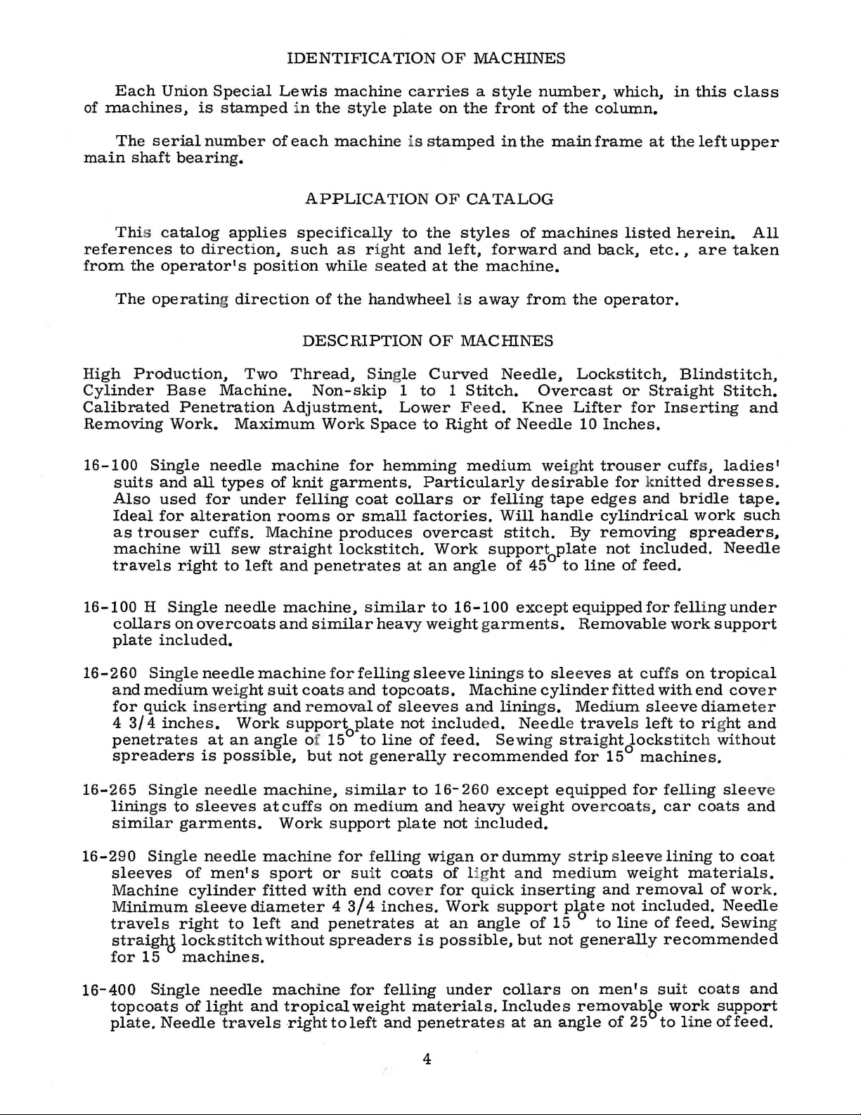
High
the
The
operating direction
Production,
Cylinder
Calibrated
Removing
16-100
Single
suits
Also
Ideal
as
trouser
machine
travels
Union
Special
is
stamped
number
Lewis
in
of
each
bearing.
to
direction,
applies
specifically
such
operator• s position
Base
Penetration
Work.
needle
and
all
used
for
for
alteration
cuffs.
will
right
Two
Machine.
Maximum
types
under
sew
to
left
Thread,
Adjustment.
machine
of
knit
felling
rooms
Machine
straight
and
machine
the
style
machine
carries
plate
is
APPLICATION
to
as rig
ht
while seated
of
the
handwheel
DESCRIPTION
Single
Non-skip
1
Lower Fee
Work
Space
for
hemming
garments.
coat
collars
or
small
produces
lockstitch.
penetrates
at
a
style
on
the
stamped
OF
CATALOG
the
styles
and
left,
at
OF
forward
the
machine.
is
away
MACHINES
Curved
to 1 Stitch.
d.
to Rig
ht
medium
Particularly
or
felling
factories.
overcast
Work
an
support
angle
front
in
the
of
from
Needle,
Knee
of
Needle
desirable
Will
stitch.
of
45°
number,
of
the
column.
main
frame
machines
and
back,
the
Lockstitch,
Overcast
Lifter
10
weight
tape
edges
handle
By
plate
to
line
which,
at
the
listed
etc
operator.
or
Straight
for
Inserting
Inches.
trouser
cuff
for knitted
and
cylindrical
removing
not
included.
of
feed.
in
this
class
left
upper
herein.
.•
are
taken
Blindstitch,
Stitch.
s,
ladies•
dresses.
bridle
work
tape.
such
spreaders,
Needle
All
and
16-100
collars
plate
16-260
and
for
4
penetrates
spreaders
16-265
linings
similar
16-290
sleeves
Machine
Minimum
travels
straighd
for
16-400
topcoats
plate.
H
included.
Single
medium
quick
3/4
inches.
Single
Single
15
Single
Needle
Single
on
overcoats
needle
weight
inserting
at
is
needle
to
sleeves
garments.
needle
of
men• s sport
cylinder
sleeve
right
lockstitch
machines.
needle
of lig
travels -right
needle
machine,
and
similar
machine for felling
suit
coats
and removal
Work
an
possible,
support
angle
of
but
15°
machine,
at
cuffs
Work
on
support
machine
or suit
fitted
diameter
to
left
without
with
and
4
penetrates
spreaders
machine
ht
and
tropical
to
similar
heavy
and
of
plate
to
not
generally
similar
medium
for
felling
end
3/4
for
weight
left
to
weight garments.
sleeve
topcoats.
sleeves
not
included.
line
of
to
16-260
and
plate
wigan
coats
cov
er
for qui
inches.
at
is
possible,
felling
materials.
and
penetrates
16-100
exceptequippedforfell
linings to
Machine
and
linings.
Needle travels left
feed.
Sewing straight
recommended
except
heavy
not
of lig
Work
an
weight
included.
or
dummy strip sleeve lining
ht
and
ck
inserting
support
angle
but
under
collars
Includes
at
Removable
sleeves
cylinder fitt
Medium
for
equipped
overcoat
medium
pl9te
of
15
not
to
generally
on
men's
removabbe
an
angle
work
at
cuf
fs
ed
with
sleeve
lockstitch wit
15°
machines.
for
felling
s,
car
weight
and
removal
not
included.
line of
recommended
suit
work
of
25
to
i
ngunder
support
on
tropic
end
diamet
to rig
ht
sle
coats
to
materials.
of
Needle
feed.
Sewin
coats
support
line
of
cov
and
hout
eve
and
coat
wor
and
feed.
al
er
er
k.
g
4
DESCRIPTION
OF
MACHINES
(Continued)
16-410
and
Needle
Sewing
16-410
slacks
removable
angle
commended
*16-420
work
angle
These
starts.
seconds
Most
fact
they
Page
B
Single
pockets
travels
straight
T
Single
and
of
15
Similar
supp~rt
of
90
machines
Use a good
at
100
of
the
are
6,
will
be
needle
in
topcoats
right
lockstitch
needle
skirts
~ork
to
feed.
on
15°
to
16-100
plate
to
line
grade
Fahrenheit.
oiling
painted
beneficial.
machine
to
machine
of
heavy
support
Sewing
machines.
included.
of
feed.
should
of
places
red.
for
and
overcoats.
left
and
without
for
materials
plate.
straight
except
to
Needle
be
oiled
straight
on
these
However,
fell:ing
penetrates
spreaders
felling
Needle
sew
printing
travels
OILING
twice
mineral
machines
reference
medium
Includes
at
is
not
bottom
producing
travels
lockstitch
press
right
daily,
before
oil
of a Saybolt
are
readily
to
and
heavyweight
removable
an
angle
recommended
to
waistband
hand
right
to
felled
left
without
felt
to
left
the
identifiable
the
oiling
wo6k
of
15
on
curtain
effect.
and
penetrates
spreaders
ink
rolls.
and
penetrates
morning
viscosity
•
diagram,
bellows
facings
support
to
line
of
15°machines.
on
trousers.
Includes
is
not
Removable
and
afternoon
of
90
to
because
Fig.
plate.
feed.
at
an
re-
at
an
125
of
the
1,
on
Please
and
to
tilt
Referring
points
marked
The
lubricated
from
Union
Point
are
lubricatedwith
be
removed
The
note
that
the
machine
to
the
·~
".
and
two
points
·~"are
with a light
Special
''B"
on
under
the
a
and
the
recommended
it
will
back
oiling
one
grease
diagram
standard
grease
speed
be
necessary
from
diagram,
marked
for
the
needle
about
part
No.
refers
wheel
replenished,
of
these
to
remove
the
sub-base
it
will
"B".
bearings
once a week.
28604
to
the
P.
cover
bearing
if
necessary.
SPEED
machines
NEEDLES
to
be
noted
over
grease.
is
head
reach
on
Tubes
that
the
the
cover,
some
there
upper
of
hook
Periodically,
1500
R.
P.M.
cylinder
of
are
main
grease
driving
the
may
the
end
oiling
two
lubrication
shaft,
be
gears.
cover
cover,
places.
and
are
ordered
which
should
*
in
Not
both
Needles
uniform
Available.
for
the
blade
Lewis
and
Class
ball
16
eye.
machines
5
are
available
in
all
the
required
sizes
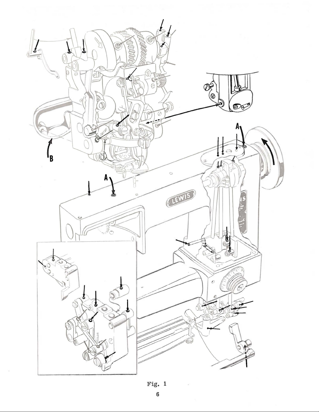
Fig.
1
6
STYLES
16-4108
16-410T
16-420
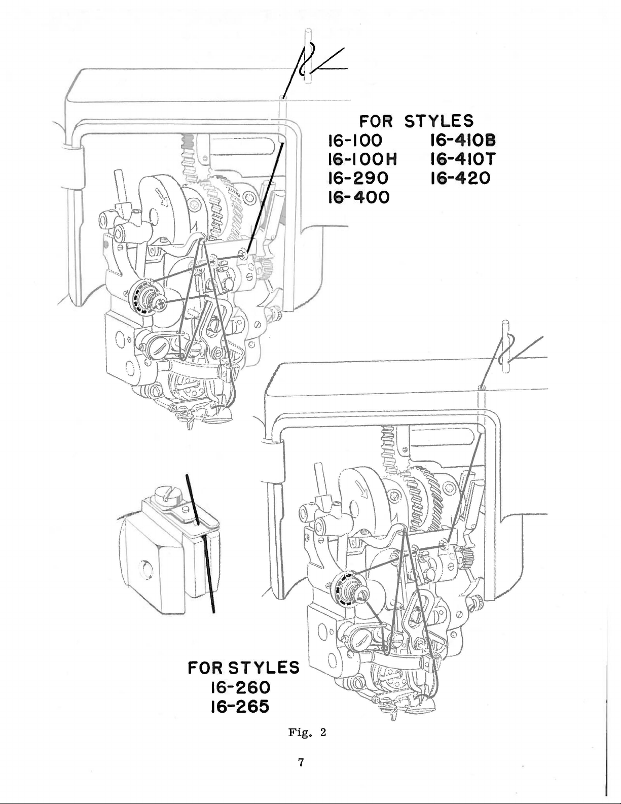
Fig.
2
7
NEEDLES
(Continued)
The following
Select
sure
that
Immediately
To
sample
read:
"100
Thread
Please
16-420
16-265
accurate
tracing
Uniform
Blade
29BC-075/029
29BC-090/036
29BC-100/040
29BC-110/044
a
needle
the
eye
have
needle
needle
or
Needles,
machines
note
are
with
the
that
threaded
the
in
that
threading,
lower.
these
types
of
is
large
discard
orders
the
type
Type
in
Styles
in
it
and
sizes
Blade
Dia.
11
. 02 9
11
.
036
11
.
040
11
.
044
the
proper
enough
any
needle
promptly
number
29BD-090/
accordance
16-100,
accordance
The
diagram
two
Styles
will
suffice.
are
available:
Ball
Eye
29BD-065/025
29BD-075/029
29BD-090/036
29BD-100/040
29BD-110/044
type
to
allow
which
and
and
free
may
accurately
should
036".
THREADING
with
16-100
with
for
are
H,
the
Styles
left
threading
hand
size
for
passage
have a hooked
be
forwarded.
16-290,
upper
diagram,
16-260
machines,
the
material
of
the
filled,
A
diagram,
16-400,
and
16-265
but
Blade
Dia.
. 02 5
. 02 9
.
036
.
040"
.
044
being
thread
or
blunt
an
empty
complete
Fig.
16-410
and
Styles
is
for
11
11
11
11
or
yarn
point.
container,
order
2,
on
B,
16-260
not
pictorially
the
purpose
sewn.
used.
would
Page
16-410
Be
a
7.
T,
and
of
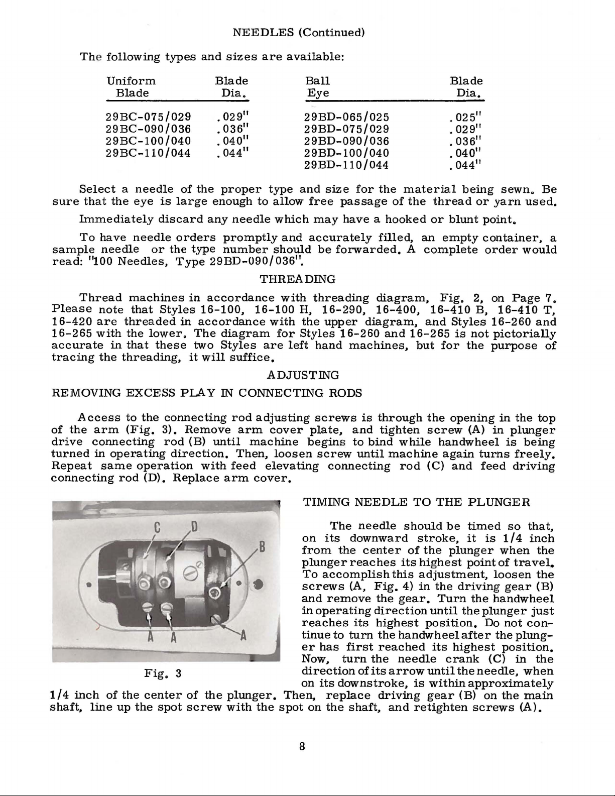
REMOVING
Access
of
the
arm
drive
turned
Repeat
connecting
in
same
connecting
1/4
inch
shaft,
of
line
EXCESS
to
the
(Fig.
operating
operation
rod
(D).
Fig.
the
center
up
the
PLAY
connecting
3).
Remove
rod
(B)
direction.
with
Replace
3
of
spot
screw
until
the
ADJUSTING
IN
CONNECTING
rod
adjusting
arm
cover
machine
Then,
feed
arm
loosen
elevating
cover.
plunger.
with
the
spot
RODS
screws
plate,
begins to
screw
connecting
TIMING
The
on
its
from
plunger
To
accomplish
screws
and
remove
in
operating
reaches
tinue
er
has
Now,
is
and
until
NEEDLE
needle
downward
the
center
reaches
(A,
its
to
turn
first
turn
through
tighten
bind
while
machine
rod
its hig
this
Fig.
4)
the
gear.
direction
highest
the
handwheel
reached
the
needle
the
screw
(C)
TO
THE
should
stroke,
of
the
adjustment,
in
the
until
position.
its
directionofitsarrowuntiltheneedle,
on
its
Then,
on
replace
the
downstroke,
driving
shaft,
and
is
within
gear
retighten
opening
(A)
handwheel
again
and
turns
feed
PLUNGER
be
timed
it
is
plunger
hest
point
driving
Turn
the
the
plunger
Do
after
highest
crank
approximately
(B)
on
screws
in
the
in
plunger
is
being
freely.
driving
so
that,
1/4
inch
when
of
trave~
loosen
gear
handwheel
just
not
con-
the
plung-
position.
(C)
in
when
the
main
(A).
top
the
the
(B)
the
8
TIMING
THE
HOOK
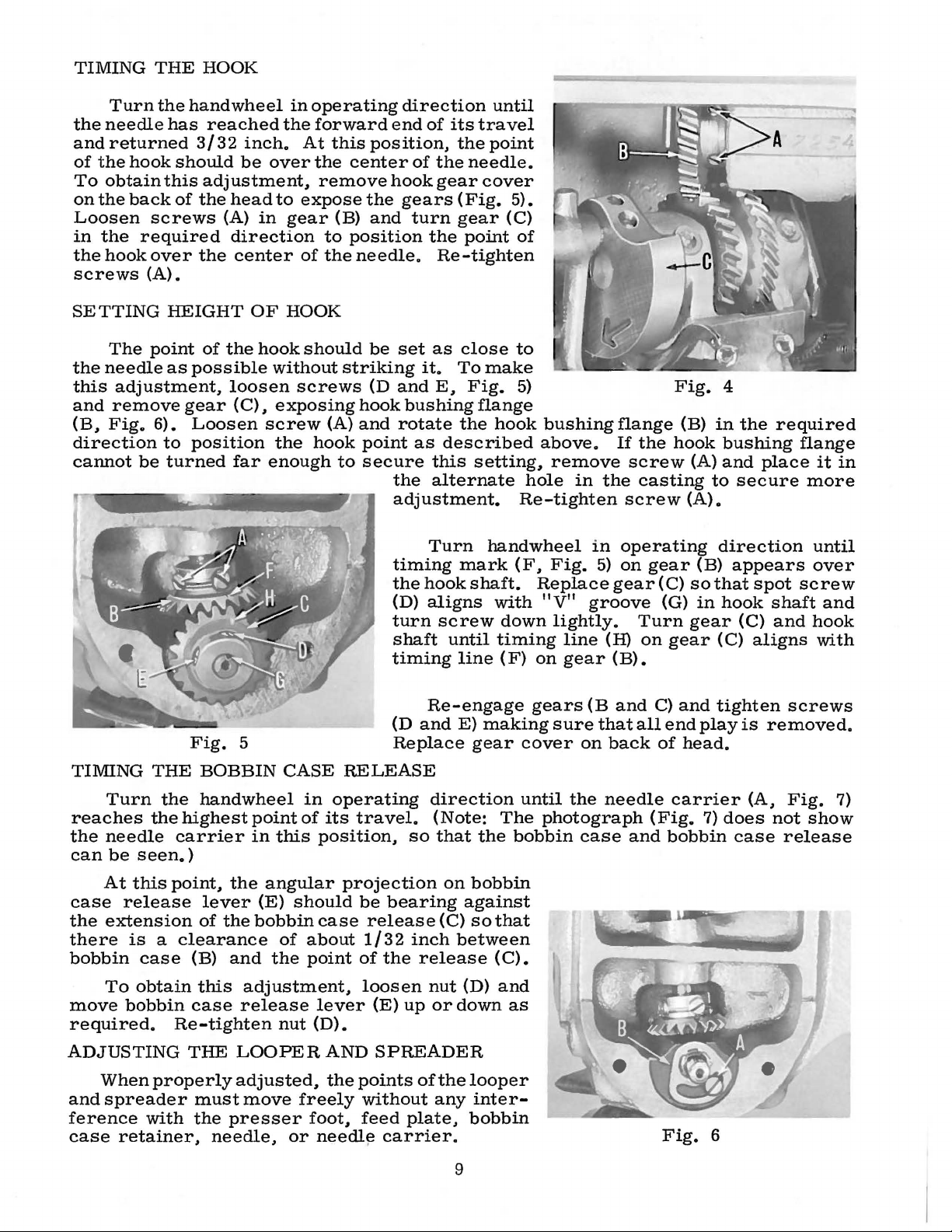
Turn
the
needle
and
returned
of
the
hook
To
obtain
on
the
back
Loosen
in
the
required
the
hook
screws
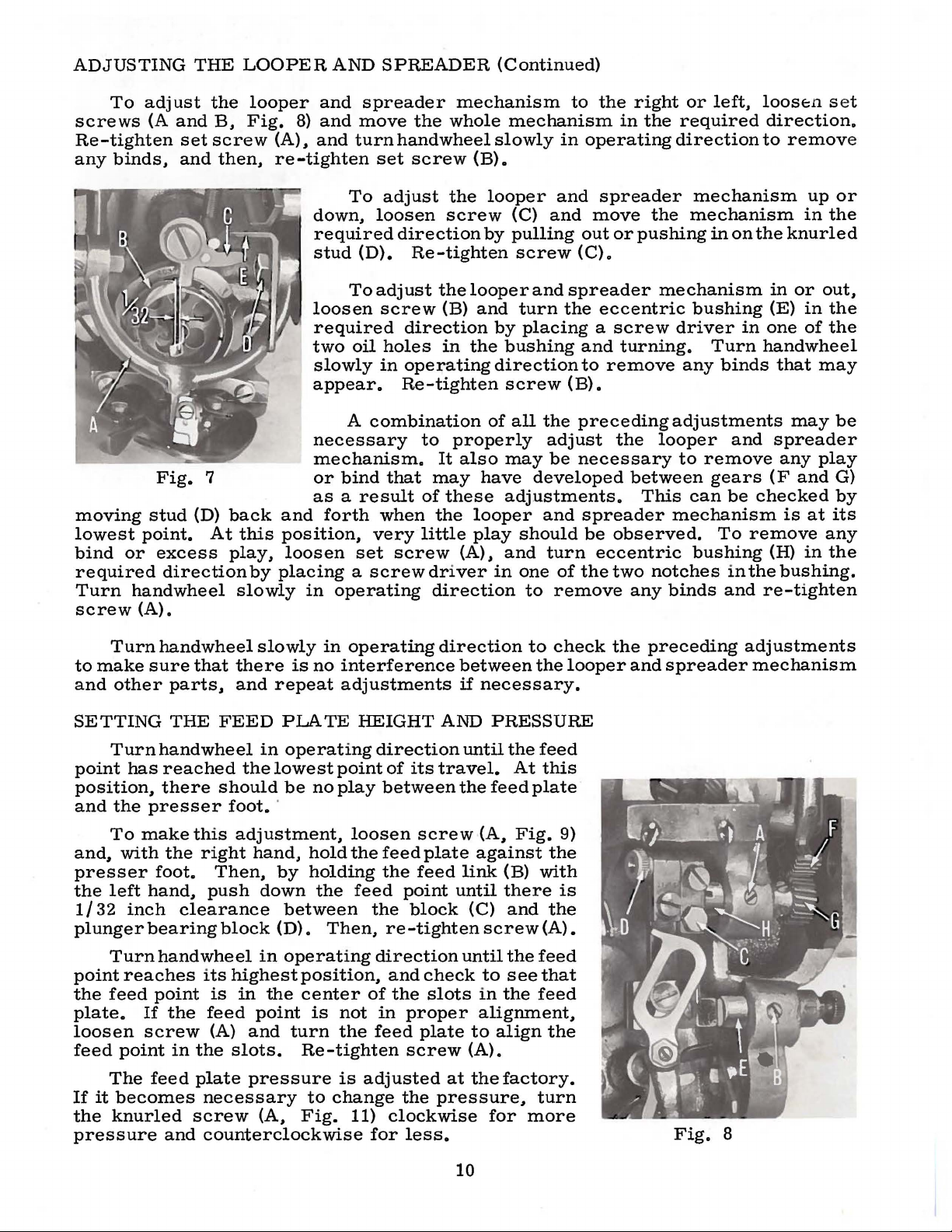
SETTING
(A).
The
the
needle
this
adjustment,
and
remove
(B.
Fig.
direction
cannot
be
the
hand
has
3/3 2 inch.
should
this
of
the
screws
over
the
HEIGHT
point
as
possible
gear
6).
Loosen
to
position
turned
wheel
reached
be
the
over
adjustment,
head
(A)
in
to
gear
direction
center
OF
HOOK
of
the
hook
without
loosen
(C).
exposing
screw
the
far
enough
in
operating
forward
At
this
the
remove
expose
(B)
to
of
the
should
screws
{A)
hook
to
end
position.
center
hook
the
and
position
needle.
be
set
striking
(D
and
hook
and
rotate
point
secure
the
adjustment.
timing
the
{D)
turn
shaft
timing
direction
of
its
the
of
the
needle.
gear
gears
turn
the
(Fig.
gear
point
Re-tighten
as
close
it.
To
E.
Fig.
bushing
the
as
described
this
alternate
Turn
mark
hook
shaft.
aligns
screw
until
line
until
travel
point
cover
5).
(C)
of
to
make
5)
flange
hook
above.
setting.
hole
Re-tighten
handwheel
(F.
Replace
with
down
timing
(F)
on
bushing
remove
in
in
Fig.
"V"
5)
groove
lightly.
line
gear
flange
If
the
screw
the
casting
screw
operating
on
gear
gear
Turn
(H)
on
{B).
Fig.
hook
{C)
{G)
gear
(B)
(A)
(A).
(B)
so
in
gear
4
in
the
bushing
and
place
to
secure
direction
appears
that
spot
hook
shaft
(C)
(C)
aligns
required
flange
it
more
until
over
screw
and
and
hook
with
in
TIMING
reaches
the
needle
can
At
case
the
extension
there
bobbin
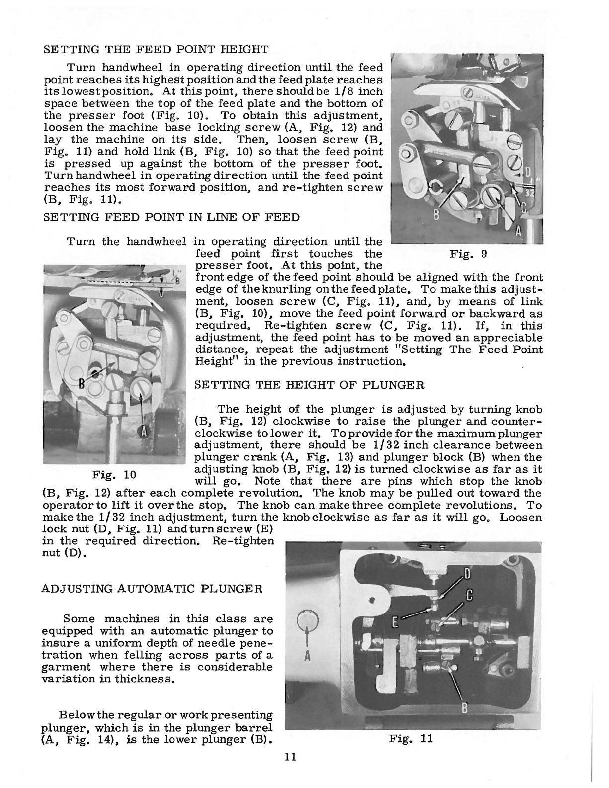
To
move
THE
Turn
the
the
be
seen.)
this
release
is a clearance
case
obtain
bobbin
required.
ADJUSTING
When
and
spreader
ference
case
properly
with
retainer.
Fig.
5
BOBBIN
handwheel
highest
carrier
point.
the
lever
of
the
(B)
and
this
adjustment.
case
release
Re-tighten
THE
LOOPER
adjusted.
must
the
move
presser
needle.
CASE
point
in
this
angular
(E)
should
bobbin
of
the
nut
or
RELEASE
in
operating
of
its
travel.
position.
projection
be
case
about
point
of
lever
(D).
AND
the
points
freely
foot,
needl~
Re-engage
(D
and
Replace
direction
(Note:
so
that
bearing
release
1/32
the
loosen
{E)
SPREADER
without
feed
{C)
inch
release
nut
up
or
of
the
any
plate.
carrier.
E)
making
gear
the
on
bobbin
against
so
between
(D)
down
looper
inter-
bobbin
cover
until
The
bobbin
that
(C).
and
as
gears
sure
(B
that
on
the
needle
photograph
case
and
all
back
and
C)
and
end
of
head.
carrier
(Fig.
bobbin
Fig.
tighten
play
7)
does
case
6
is
removed.
(A.
not
release
screws
Fig.
show
7)
9
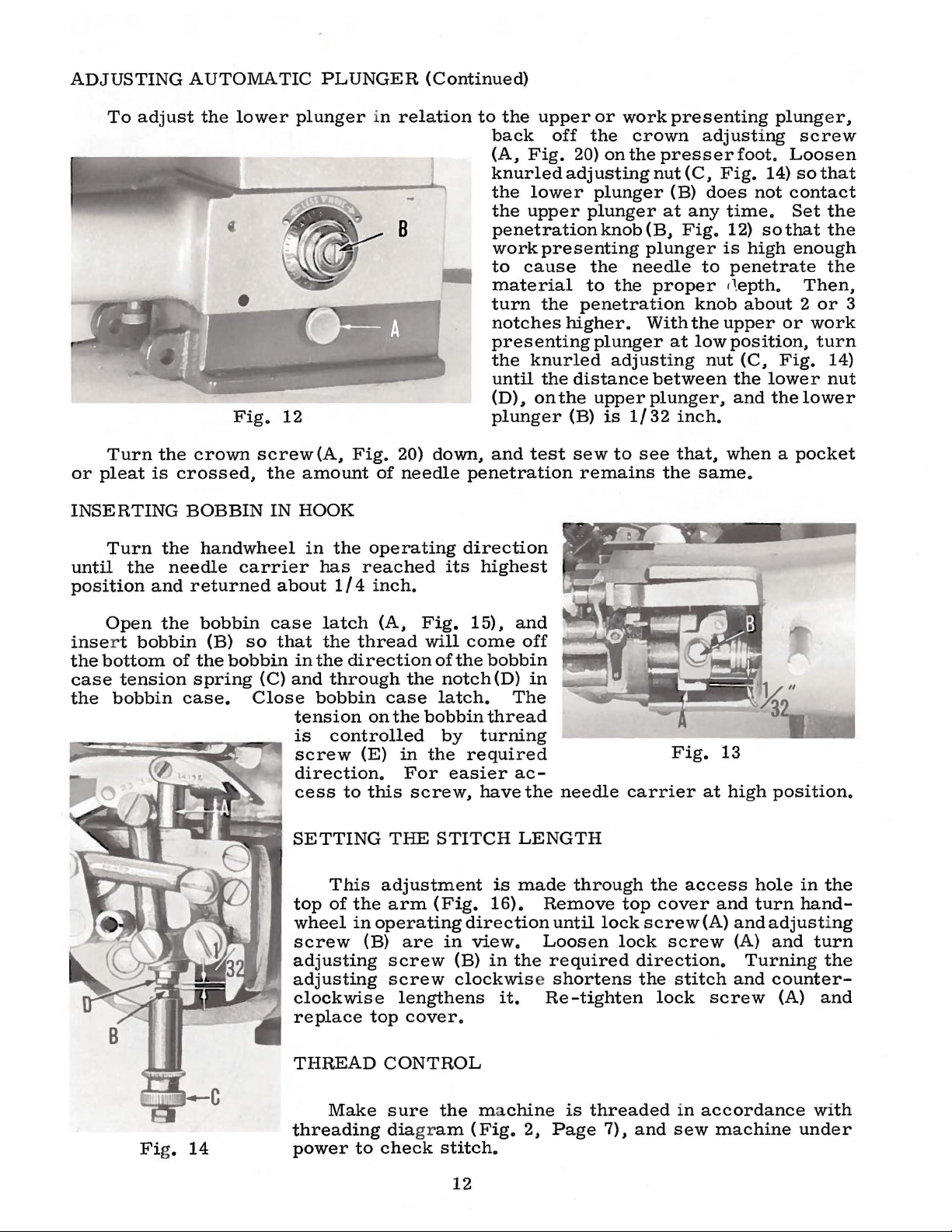
ADJUSTING
To
adjust
screws
(A
Re-tighten
any
binds.
Fig.
moving
lowest
bind
required
Turn
screw
stud
point.
or
excess
direction
handwheel
(A).
THE
and
set
and
(D)
the
B.
screw
then.
7
back
At
this
play.
slowly
LOOPER
looper
Fig.
(A).
8)
AND
and
and
and
re-tighten
down.
required
stud
loosen
required
two
slowly
appear.
necessary
mechanism.
or
bind
as a result
and
forth
position.
loosen
by
placing a screw
in
operating
SPREADER
spreader
move
turn
To
hand
set
screw
adjust
the
loosen
direction
(D).
To
Re-tighten
adjust
screw
direction
oil
holes
in
operating
Re-tighten
A
combination
that
when
very
set
screw
mechanism
whole
wheel
(B).
the
screw
the
looper
(B)
in
the
to
properly
It
also
may
of
these
the
looper
little
play
(A).
driver
direction
(Continued)
mechanism
slowly
looper
(C)
by
pulling
in
and
and
screw
and
and
turn
by
placing a screw
bushing
direction
screw
of
all
the
adjust
may
be
have
developed
adjustments.
and
should
and
turn
in
one
of
to
remove
to
the
in
operating
spreader
move
out
or
(C).
spreader
the
eccentric
and
turning.
to
remove
(B).
preceding
the
necessary
spreader
be
observed.
eccentric
the
two
right
the
or
required
direction
the
mechanism
pushing
mechanism
driver
any
adjustments
looper
to
between
This
can
mechanism
notches
any
binds
left.
loose:n
direction.
to
mechanism
in
on
the
in
bushing
Turn
binds
(E)
in
one
handwheel
that
and
spreader
remove
gears
To
bushing
be
remove
in
the
and
checked
(F
(H)
re-tighten
s et
remov
up
or
in
the
knurled
or
out.
in
the
of
the
may
may
be
any
play
and
G)
by
is
at
its
any
in
the
bushing.
e
Turn
to
make
and
sure
other
SETTING
Turn
point
has
position.
and
the
presser
To
make
and.
with
presser
the
left
hand.
1/32
plunger
inch
bearing
Turn
point
the
plate.
loosen
feed
reaches its
feed
If
screw
point
The
If
it
becomes
the
knurled
pressure
handwheel
that
parts.
THE
FEED
handwheel
reached
there
should
this
the
right
foot.
Then.
push
clearance
block
hand
wheel
point
the
is
feed
(A)
in
the
feed
plate
necessary
screw
and
counterclockwise
slowly
there
and
is
repeat
PLATE
in
operating
the
lowest
be
foot.
·
adjustment.
hand.
by
down
between
(D).
in
operating
highest
in
the
position.
center
point
and
turn
slots.
Re-tighten
pressure
to
(A.
Fig.
in
operating
no
interference
adjustments
HEIGHT
point
no
play
loosen
hold
the
holding
the
feed
Then.
of
is
not
the
is
adjusted
change
11)
for
direction
of
its
between
screw
feed
plate
the
feed
point
the
block
re-tighten
direction
and
check
the
slots
in
proper
feed
plate
screw
the
pressure.
clockwise
less.
direction
between
if
necessary.
AND
PRESSURE
until
travel.
the
feed
(A.
against
link
until
(C)
screw
until
to
in
alignment.
to
align
(A).
at
the
factory.
for
to
the
the
At
plate
Fig.
(B)
there
and
the
see
the
feed
turn
more
check
feed
this
9)
the
with
is
the
(A).
feed
that
the
the
looper
preceding
and
spreader
Fig.
adjustments
mechanism
8
10
SETTING
THE
FEED
POINT
HEIGHT
Turn
point
its
space
the
loosen
lay
Fig.
is
Turn
reaches
(B,
SETTING
reaches
lowest
between
presser
the
the
11)
pressed
hand
Fig.
Turn
handwheel
its
position.
the
foot
machine
machine
and
hold
up
against
wheel
its
most
11).
FEED
the
handwheel
in
highest
At
top
(Fig.
base
on
its
link
in
operating
forward
POINT
operating
position
this
point,
of
the
feed
10).
locking
side.
(B,
Fig.
the
bottom
direction
position,
IN
LINE
in
operating
feed
presser
front
edge
ment,
(B,
Fig.
required.
adjustment,
distance,
Height"
and
To
Then,
10)
point
edge
of
loosen
direction
the
feed
there
obtain
screw
OF
the
in
should
plate
loosen
so
that
of
the
until
and
FEED
direction
first
foot.
of
the
knurling
10).
Re-tighten
the
repeat
the
until
plate
be
and
the
this
adjustment,
(A,
Fig.
screw
the
presser
the
re-tighten
touches
At
this
feed
point
on
screw
move
previous
feed
the
(C,
the
point
the
feed
reaches
1/8
inch
bottom
12)
feed
feed
until
point,
the
feed
screw
adjustment
instruction.
of
and
(B,
point
foot.
point
screw
the
the
the
should
feed
Fig.
point
has
be
plate.
11).,
forward
(C,
to
be
"Setting
aligned
To
and,
Fig.
moved
Fig.
make
by
means
or
11).
an
The
9
with
the
this
adjust-
of
backward
If,
in
appreciable
Feed
front
link
as
this
Point
Fig.
(B,
Fig.
operator
make
lock
in
nut
ADJUSTING
equipped
insure a uniform
tration
garment
variation
the
nut
the
(D).
Some
required
when
10
12)
after
to
lift
1/32
(D,
in
inch
Fig.
AUTOMATIC
machines
with
where
an
felling
thickness.
each
it
over
adjustment,
11)
andturnscrew
direction.
in
automatic
depth
across
there
SETTING
(B,
clockwise
adjustment,
plunger
adjusting
will
complete
the
stop.
Re-tighten
PLUNGER
this
class
plunger
of
needle
parts
is
considerable
The
height
Fig.
crank
go.
revolution.
The
turn
pene-
THE
12)
clockwise
to
lower
there
knob
Note
knob
the
(E)
are
to
of
a
HEIGHT
of
the
it.
should
(A,
Fig.
(B,
Fig.
that
The
can
knob
clockwise
?
A
OF
plunger
to
To
13)
12)
there
knob
make
PLUNGER
is
raise
provide
be
1/32
and
plunger
is
turned
are
may
three
as
adjusted
the
plunger
for
the
inch
clockwise
pins
complete
be
far
which
pulled
as
by
turning
and
maximum
clearance
block
it
(B)
as
stop
out
revolutions.
will
go.
counter-
plunger
between
when
far
the
toward
Loosen
knob
the
as
it
knob
the
To
Belowthe
plunger,
(A,
Fig.
regular
which
14),
is
is
in
the
or
work
the
plunger
lower
presenting
barrel
plunger
(B).
11
Fig.
11
ADJUSTING
To
adjust
AUTOMATIC
the
lower
•
Fig.
plunger
12
PLUNGER
in
relation
8
(Continued)
to
the
back
(A,
knurled
the
the
penetrationknob(B,
work
to
material
turn
notches
presenting
the
until
(D),
plunger
upper
off
Fig.
20)
adjusting
lower
upper
presenting
cause
the
penetration
higher.
knurled
the
distance
on
the
(B)
or
work
the
crown
on
the
plunger
plunger
the
needle
to
the
plunger
adjusting
upper
is
1/32
presenting
adjusting
presser
nut ( C,
(B)
at
any
Fig.
plunger
to
proper
knob
With
the
at
low
between
plunger,
inch.
foot.
Fig.
does
time.
12)
is
high
penetrate
,l.
epth.
about 2 or
upper
position,
nut
(C,
the
and
plunger,
Loosen
14)
not
contact
Set
sothat
enough
or
Fig.
lower
the
screw
so
that
the
the
the
Then,
work
turn
14)
nut
lower
3
Turn
or
pleat
INSERTING
Turn
until
position
Open
inse
r t
the
bottom
case
the
the
is
the
the
and
the
bobbin
tension
bobbin
crown
crossed,
BOBBIN
handwheel
needle
returned
bobbin
(B)
of
the
spring
case.
screw
the
IN
carrier
about
case
so
that
bobbin
(C)
Close
(A,
Fig.
amount
HOOK
in
the
has
reached
1/4
latch
the
thread
in
the
direction
and
through
bobbin
tension
is
controlled
screw
direction.
cess
SETTING
top
wheel
screw
adjusting
adjusting
clockwise
replace
to
This
of
the
in
(E)
20)
of
needle
operating
inch.
(A,
Fig.
will
the
case
on
the
bobbin
in
the
For
this
screw,
THE
adjustment
arm
operating
(B)
are
screw
screw
lengthens
top
cover.
down,
ofthe
notch(D)
latch.
by
STITCH
(Fig.
in
and
test
penetration
direction
its
highest
15),
and
come
required
easier
direction
view.
(B)
clockwise shortens
off
bobbin
in
The
thread
turning
ac-
have
the
LENGTH
is
made
16).
in
the
it.
needle
Remove
until
Loosen
required
Re-tighten
sew
to
remains
carrier
through
top
lock
lock
see
that,
the
same.
Fig.
at
the
access
cover
screw(A)
screw
direction.
the
stitch
lock
when a pocket
13
high
position.
hole
in
and
turn
hand-
and
adjusting
(A)
and
Turning
and
counter-
screw
(A)
the
turn
the
and
Fi
g.
14
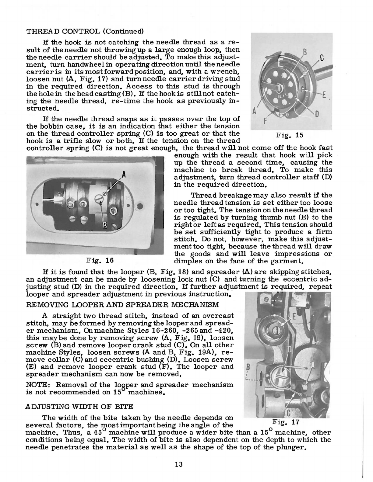
THREAD
Make
threading
power
CONTROL
sure
diagram
to
check
the
ma
(Fig.
stitch.
12
chine
2,
Page
is
threaded
7),
and
in
accordance
sew
machine
with
under
THREAD
If
the
sult
of
the
the
needle
ment.
carrier
loosen
in
the
ing
structed.
the
on
hook
controller
turn
is
nut
the
required
hole
in
the
needle
If
the
bobbin
the
thread
is a trifle
CONTROL
hook
needle
carrier
in
(A.
the
needle
case,
spring
is
not
not
should
handwheelin
its
most
Fig.
direction.
head
casting
thread.
thread
it
controller
slow
(C)
(Continued)
catching
throwing
be
adjusted.
operating
forward
17)
and
turn
Access
(B).
re-time
snaps
is
an
indication
spring
or
both.
is
not
great
the
needle
up a large
direction
position.
needle
to
If
the
hook
the
hook
as
it
passes
that
(C)
is
If
the
tension
enough.
thread
enough
To
make
until
and.
with a wrench.
carrier
this
stud
is
still
as
previously
over
either
too
great
on
the
enough
up
the
machine
adjustment.
in
the
as a re-
loop.
this
adjust-
the
needle
driving
is
through
not
catch-
the
top
the
tension
or
that
the
thread
thread
with
thread
to
turn
required
then
stud
in-
of
the
will
the
result
a
second
break
thread
direction.
not
thread.
A
come
that
time.
controller
Fig.
off
hook
To
15
the
hook
will
causing
make
staff
fast
pick
the
this
(D)
If
it
is
an
adjustment
justing
looper
REMOVING
stitch.
er
this
screw
machine
move
(E)
spreader
NOTE:
is
not
stud
and
straight
A
may
mechanism.
maybe
(B)
and
Styles.
collar
and
remove
mechanism
Removal
recommended
Fig.
found
(D)
spreader
LOOPER
be
done
can
in
two
formed
On
by
remove
loosen
(C)
and
looper
that
of
16
the
be
made
the
required
adjustment
AND
thread
by
removing
machine
removing
looper
screws
eccentric
crank
can
the
lospe
on
15
looper
SPREADER
stitch.
Styles
now
machines.
by
loosening
direction.
in
screw
crank
(A
bushing
stud
be
·r
and
(B.
instead
16-260.
removed.
needle
or
is
right
be
stitch.
ment
the
dimples
Fig.
18)
lock
previous
MECHANISM
the
looper
(A.
Fig.
stud
(C).
and
B.
Fig.
(D).
(F).
The
spreader
Thread
thread
too
tight.
regulated
or
left
set
sufficiently
Do
too
tight.
goods
on
and
spreader
nut
(C)
If
further
instruction.
of
an
overcast
and
spread-
-265
and
19).
loosen
On
all
19A).
Loosen
looper
mechanism
breakage
tension
The
tension
by
turning
as
required.
not.
however.
because
and
will
the
face
and
adjustment
-420.
other
re-
screw
and
may
is
thumb
tight
the
leave
of
the
(A)
are
turning
B
,
,
,
also
set
either
on
the
needle
nut
This
tension
to
produce
make
thread
impressions
garment.
skipping
the
eccentric
is
required.
result
too
(E)
this
will
stitches.
if
the
loose
thread
to
the
should
a
firm
adjust-
draw
or
ad-
repeat
ADJUSTING
The
several
machine.
conditions
needle
penetrates
WIDTH
width
factors.
of
the
Thus. a 45°
being
equal.
the
the
OF
BITE
bite
most
machine
The
material
taken
important
by
will
width
as
the
needle
being
produce a wider
of
bite
well
as
13
the
is
the
depends
angle
also
shape
of
bite
dependent
of
on
the
than a 15°
on
the
top
the
of
Flg.
machine.
depth
the
plunger.
.
7
1
other
to
which
the
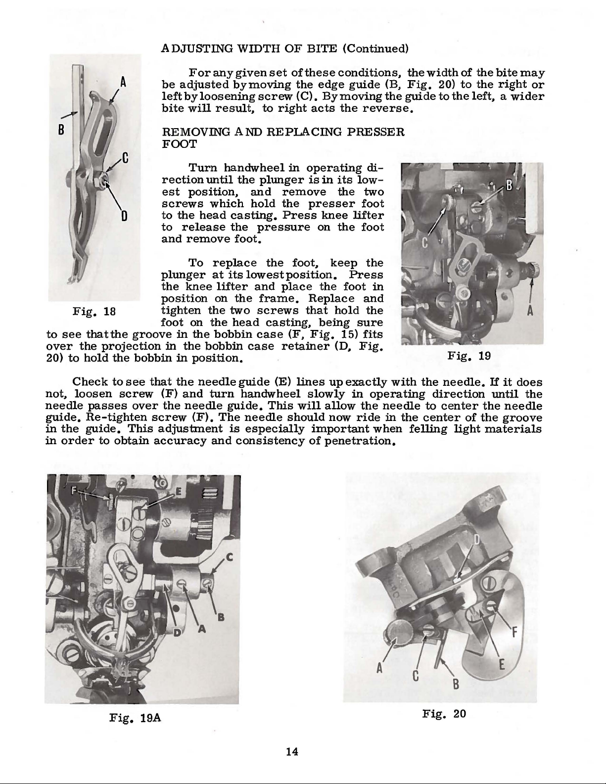
ADJUSTING
WIDTH
OF
BITE
(Continued)
to
see
over
20)
Fig.
the
to
18
thatthe
projection
hold
the
A
groove
bobbin
Foranygivenset
be
adjusted
left
by
loosening
bite
will
result~
REMOVING
FOOT
Turn
rection
est
screws
to
to
and
plunger
the
position
tighten
foot
in
until
position~
which
the
head
release
remove
To
replace
at
knee
lifter
on
the
on
the
in
the
bobbin
the
bobbin
in
position.
bymoving
screw
to
AND
REPLACING
handwheel
the
plunger
and
hold
casting.
the
pressure
foot.
the
its
lowest
and
the
frame.
two
screws
head
casting~
case
case
oftheseconditions~
the
(C).
right
edge
acts
guide
Bymovingthe
the
reverse.
thewidthof
(B.
Fig.
guide
PRESSER
in
operating
is
remove
the
presser
Press
on
foot~
position.
place
the
Replace
that
being
(F~
Fig.
retainer
in
its
the
knee
the
keep
hold
(D~
low-
lifter
Press
foot
sure
15)
Fig.
di-
two
foot
foot
the
in
and
the
fits
20)
to
Fig.
thebitemay
to
the
the
left~
19
right
a
wider
or
Check
not~
loosen
needle
guide.
in
the
in
order
to
see
screw
passes
over
Re-tighten
guide.
to
This
obtain
that
the
(F)
and
the
needle
screw
(F).
adjustment
accuracy
needle
turn
guide.
The
and
guide
(E)
handwheel
This
needle
is
especially
consistency
lines
slowly
will
should
important
of
up
exactly
in
operating
allow
now
the
ride
needle
when
penetration.
with
in
the
the
center
felling
needle.
direction
to
center
light
If
the
of
the
materials
it
until
needle
groove
does
the
Fig.
19A
14
Fig.
20
 Loading...