

Lewis 150-1, 150-5, 150-6, 150-GTS, 150-7 User Manual
...
w s
PARTS and INSTRUCTIONS
400
N.
150
~
Franklin
Catalogue
194-5
Class Machines
Models
150-1
150-5
150-6
150-GTS
150-7
PRODUCT OF
St.
150-9
150-15
150-16
150-17
150-20
150-23
®
MACHINECOMPANY
Chicago,
Ill.
60610
PRINTED
IN
U.
S.
A.
LEW!:;;
CLASS
150
MACHINES
Adjusting
Adjusting
Belt
Loop
Loops.
Cylinder
Feeds
Flared
Feed
Feed
Folders
General
Hemming
••.•..
Plates
Plate
Plate
Feed
Chart
Looper
Parts
• • •
Base
Skirts.
•••••••••
Instructions
Flared
8.
Parts
••••••••••••
••••••••••••
for
•••••.•••••••.•
Parts
.•
Holders.
Skirts: Parts
to
3/8"
and
•••
adjust
Plates .•••.........•.•
INDEX
and
5/'6"
their
pressure
wide
Adjustments.
for,
See
of
PAGE
13 , 14
16-19
93,94
12
11,114
1 1
115
116
117
7-19
11,53
Instructions
Instructions
Instructions
Instructions
Model
Model
Model
Numbers
150-1 .'.
Additional
Plates
150-5
Additional
See
Plates
for
for
-
for
for
Parts
Model
Parts
for
Belt
Loop
General
and
•••••••••••••••
Model
•••••••
Ordering
Using
Serial
for
Model
150-1
for
Model
Catalogue.
150-1
Machine
Parts
Numbers
150-l
•••••••••
150-5
••••••••••••••
••
••••••
91,92
7-19
5
5
5
44-54
54
46-53,110
56
56
46-53,110
2.
Model
Model
Model
Model
Mode 1 150-15
150-6
Addition
instructions
Plates
Additional
Instructions
Plates
Additional
Instructions
Plates
Additional
Plates
Additional
Plates
a l
for
150-6TS
for
150-7
for
150-9
for
for
LEWIS
•...••.••••••••••
Parts
Model
Parts
Model
Parts
Model
Parts
Model
Parts
Model
for
for
Model
150-6.
••••••••
for
for
Model
150-6TS
•••••••••••
for
for
Model
150-7
••••••••••••
for
150-9
••••••••••••••••
for
150-15
CLASS
INDEX
Model
Model
Model
Model
Model
150-6
150-6
150-6TS
150-6TS
•
150-7
150-7
•••
150-9
••••••••••••••
150-15
••••••••••••••••••
•••••
•
••••
•••
150
MACHINES
••
••
•••
•••••••••••
. . . .
..
PAGE
58-60
60
57
59,111
61-65
64,65
61
63 J 111
66-71
70,71
67,68
69,113
72-76
75-76
74,111
77-80
80
79 J 111
Model
Model
Model
Model
Needles
Oiling
Parts
150-16
Additional
Instructions
Plates
150-17
Additional
See
Plates
150-20
150-23,
Additional
Instructions
Plates
Machine
List
for
Model
Parts
Parts
for
Model
•••••••
including
••••••••
Parts
for
for
for
Model
150-16
••••••••••••••••
for
Model
for
for
Model
150-23
•
all
Model
150-16
Model
150-l
Model
150-23
••••••••••
Models
150-16
••••••••
150-17
150-23
•••••••••••
••••••••••••••
•••••••••
•
•••••••
••••••••••••••
81-93
86-90,93
91-92
82-85,112
96
97
46-53,111
81-94
98-109
106-109
98-100
102-
105,113
8
9
20-43
3
Plate
Presser
Regulating
Ridge
Ridge
Retainer
Speed
Serial
Thread
Threading
Timing
Numbers
Forming
Forming
of
Numbers
Feet
Length of
or
Cloth
Machine
••••••••
Machine
and
Adjusting
LEWIS
-See
••••••••••
Disc
Disc
Clamp
•••••
and
CLASS
INDEX
Models.
Stitch
Regulator
.••
150
MACHINES
See
below
•••••••••
• • • • • • • • • • • • • • •
. . . . . . . . . . . . . . . . . . .
Model
Charts
Numbers
•••••••••••••••••
••
PAGE
9,118,119
12
9,
10,
120
10
19,20
9
5
8
7
13,14
Unpacking
Machine
••••••••••••.••••.•••••
7
4
PLATE
NO.
l
lA
2
3
4
5
6
7
8
9
10
ll
12
13
14
15
16
17
18
19
20
21
22
23
24
25
Timing
Timing
Parts
Parts
Parts
Parts
Parts
Parts
Parts
Parts
Additional
Additional
Additional
Additional
Additional
Additional
Additional
Additional
Additional
Additional
Additional
Additional
Additional
Additional
Additional
Additional
For
For
For
For
For
For
For
For
150-6TS
150-l
150-6,
150-7
LEWIS
CLASS
150
INDEX
PLJ\TES
Chart
••.•.••••••••.••••••
Chart ...........•........
Model
Modell50-l
Model
Model
Model
Model
Model
Model
Parts
Parts
.••.••......•..••••••.
Parts
Parts
Parts
Parts
Parts
Parts
Parts
Parts
Parts
Parts
Parts
and
150-5
Parts
150-9,
Parts
Parts
and
150-23
150-l
150-l
150-l
150-l
150-l
150-l
150-l
For
Model
For
Models
For
Model
For
Model
For
Modell50-15
For
Model
For
Model
For
Model
For
Mo,del
For
Model
For
Model
For
Model
For
Models,
•••••••••••••••••
For
Models,
150-15
For
For
and
Model
Models,
••••••••••••••.•
MACHINES
••.••••••••••
•••••••••••••
•••••••••••••
•••••••••••••
150-6
150-6,
150-7
150-9
150-16
150-16
150-16
150-23
150-23
150-23
150-23
150-17
150-16
••••••
••••••
••••••
•••••
•••••
•••••
•••••
•••••
•••••
•••••
•••••
••••••
•••••
PAGE
NO.
13
14
46
47
48
49
50
51
52
53
59
63
69
74
79
33
84
85
102
103
104
105
110
lll
112
113
5
The
in
compiling
used
class
under
machine
show
in
150
Additional
each
To
the
The
of
***************************************
The
in
INSTRUCTIONS
TO
Model
the
Machines.
find a part
for
page
Model
the
the
150-1
this
Model
parts
model
which
number,
machine.
Serial
arm
catalogue
150-1,
used
number.
needed,
the
No.
No.
under
FOR
ORDER
Machine
part
is
of
USING
are
used
to
is
referring
located
each
the
top
PARTS
is
the
that
is
in
make
note
wanted,
to
on
machine
cover.
CATALOGUE
basic
the
all
each
model
the
top
machine
majority
the
models
Model
number
and
the
model.
of
the
is
stamped
head
of
of
are
listed
on
index
used
parts
the
the
will
Turn
obtain
part
is
to
at
the
The
section
referred
If
for
description
January,
***************************************
State
when
part
part
Model
ordering
to
the
number.
common
bottom
parts
are
the
to
at
the
number
1971
No.
parts.
plate
to
Modell50-l,
of
the
listed
additional
bottom
is
and
best
and
showing
If
part
page
and
of
known
plate
Serial
cannot
of
parts
plate
parts
page
turn
for
No.
of
drawings
be
located,
orto
the
listed.
drawing
used
of
parts
to
General
locating
over
machine
of
machine
model
in
listed.
part.
referred
each
the
parts
then
model
models
list
to
the

s
11
1,
s la
11d
plates,
s
ubj
as
presser
•.
1rd,
22,
cts:
The
pbte
see lists
23,
feet,
24,
drawings
folders
on
last
and
25.
Feeds.
Feed
Folders.
Presser
Ridge
show
and
pages
Refer
Plates.
Forming
only
etc.
of
catalogue,
to
index
Feet.
the
For
for
Disc.
standard
parts
also
following
parts
other
see
than
7
GENERAL
ADJUSTMENT,
UNPACKING
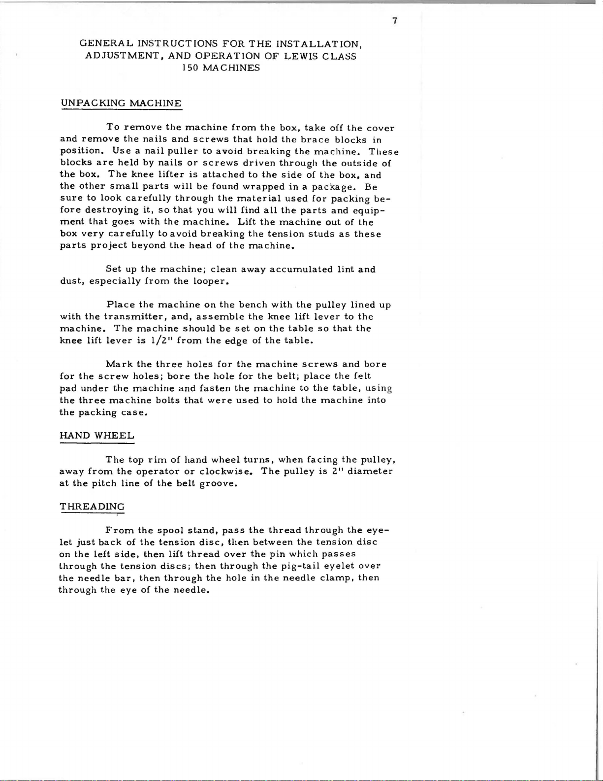
To
and
remove
position.
blocks
the
the
sure
fore
ment
box
parts
dust,
with
machine.
knee
are
box.
The
other
small
to
look
destroying
that
very
carefully
project
Set
especially
Place
the
transmitter,
lift
lever
goes
INSTRUCTIONS
MACHINE
remove
the
nails
Use a nail
held
by
knee
parts
carefully
it,
with
beyond
up
the
from
the
The
machine
is
1/2
AND
150
the
machine
and
puller
nails
or
lifter
will
through
so
that
the
machine.
to
avoid
the
machine;
the
machine
and,
should
11
from
FOR
OPERATION
MACHINES
from
screws
to
screws
is
attached
be
you
breaking
head
looper.
on
assemble
avoid
found
the
will
of
clean
the
the
be
edge
that
the
set
THE
OF
the
hold
breaking
driven
to
the
wrapped
material
find
all
Lift
the
the
machine.
away
bench
the
on
of
the
INSTALLATION,
LEWIS
box,
the
through
side
in a package.
used
the
machine
tension
accumulated
with
knee
the
table
table.
take
brace
the
of
parts
the
lift
CLA::iS
off
machine.
the
the
for
packing
out
studs
pulley
lever
so
the
blocks
outside
box,
and
of
as
lint
to
that
cover
and
Be
equip-
the
these
and
lined
the
the
in
These
of
be-
up
Mark
for
the
screw
pad
under
the
three
machine
the
packing
HAND
away
at
the
WHEEL
The
from
pitch
THREADING
From
let
just
back
on
the
left
through
the
through
the
needle
the
the
case.
top
the
line
of
side,
tension
bar,
eye
the
three
holes;
machine
bolts
rim
operator
of
the
the
spool
the
tension
then
discs;
then
of
the
holes
bore
and
that
of
hand
or
belt
stand,
lift
thread
through
needle.
for
the
hole
fasten
were
wheel
clockwise.
groove.
pass
disc,
over
then
through
the
the
for
the
used
then
hole
machine
the
machine
to
turns,
The
the
between
the
the
in
the
belt;
hold
when
pulley
thread
pin
which
pig-tail
needle
screws
place
to
the
the
facing
through
the
the
table,
machine
is
2"
tension
passes
eyelet
clamp,
and
bore
felt
usin
the
pulley,
diameter
the
eye-
disc
over
then
g
into
8
REMOV1NG
See
plates
will
signs
changes
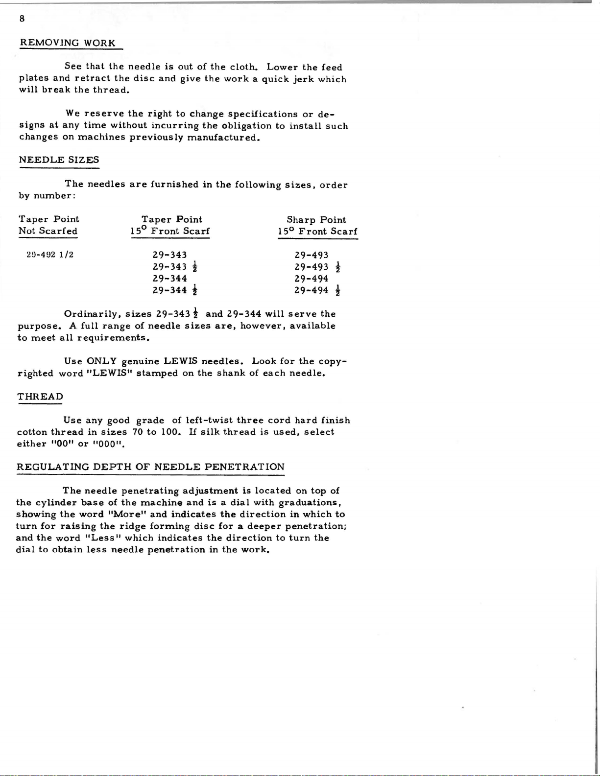
NEEDLE
by
Taper
Not
purpose.
to
break
at
number:
Scarfed
2!J-492
meet
and
We
any
on
The
Point
1/2
Ordinarily,
all
WORK
that
the
retract
the
thread.
reserve
time
without
machines
SIZES
needles
A
full
range
requirements.
needle
the
disc
the
previously
are
15°
sizes
of
is
and
right
incurring
furnished
Taper
Front
29-343
29-343
29-344
29-344
29-343!
needle
out
of
the
give
the
to
change
the
manufactured.
in
the
Point
Scarf
i
!
and
sizes
are,
cloth.
work a quick
specifications
obligation
following
29-344
Lower
will
however,
jerk
to
install
sizes,
Sharp
15°
serve
available
the
which
or
de-
Front
29-493
29-493
29-494
29-494
feed
such
order
Point
Scarf
!
!
the
Use
righted
THREAD
cotton
either
REGULATING
the
showing
turn
and
dial
word
Use
thread
"00"
The
cylinder
the
for
raising
the
word
to
obtain
ONLY
"LEWIS"
any
in
sizes
or
"000".
DEPTH
needle
base
word
the
"Less
less
genuine
good
70
OF
penetrating
of
the
"More"
ridge
11
which
needle
LEWIS
stamped
grade
to
100.
NEEDLE
machine
and
forming
indicates
penetration
needles.
on
the
of
left-twist
If
silk
adjustment
and
indicates
disc
Look
shank
PENETRATION
is a dial
for a deeper
the
in
three
thread
is
the
direction
direction
the
work.
of
each
cord
is
located
with
for
the
needle.
hard
used,
select
on
top
graduations,
in
which
penetration;
to
turn
the
copy-
finish
of
to
9
SKIPPING
Examine
over.
Replacing
stitches.
REPLACING
Insert
and
tighten
needle
IMPORT
guide.
ANT --OIL
SPEED
The
3000
stitches
recommended
Speed
may
TIMING
All
screws.
STITCHES
point
needle
NEEDLE
needle
set
screw.
LEWIS
per
minute.
in
starting a new
be
increased
basic
driving
of
needle
will
generally
into
needle
Needle
MACHINE
Class
150
A
to
suit
parts
to
should
DAILY
machines
speed
machine
operator
are
see
remedy
carrier
bear
of
1800
properly
if
it
is
as
far
slightly
can
be
to
2000
or
with a new
or
class
timed
blunt
or
skipping
as
possible
on
operated
stitches
of
work.
with
turned
of
the
up
is
operator.
spot
to
PRESSER
ble
and
foot
up
11
.010
tension.
needle
RIDGE
slot
in
the
in
relation
150-17.
in
question.
play
to
justing
first
be
FOOT
Place
with
the
or
down
guide
freely.
FORMING
The
disc
presser
to
the
For
other
Before
the
cradle
the
pivot
loosened
new
needle
point
so
that
Observe
DISC
must
foot,
needle,
models,
setting
140-11.
bearing
and
the
in
directly
the
point
that
{Refer
be
adjusted
and
Models
the
disc
Any
screw
tension
the
over
shank
to
so
refer
needle
the
of
the
of
Plate
to
that
the
150-1,
to
special
be
sure
end
play
18-869,
of
Spring
carrier
needle
needle
needle
lA)
be
in
nose
150-6,
that
can
Set
as
guide
is
under
passes
.
the
center
of
the
150-6TS,
instructions
there
be
taken
Screw
21-377
far
as
adjust
scant
over
of
disc
is
is
no
end
up
by
1003
must
released.
possi-
the
the
the
set
150-7,
on
model
ad-
10
Adjust
cradle
hand,
I
003
setting
even
loosen
crank
disc
so
slot
in
needle
disc
joins
the
disc
1158
set
the
shaft.
hand
shaft
ling
the
engages
nut
20
Pivot
must
then
to
lock
Adjust
is
with
To
set
448-131
that
presser
will
is
in
crank
collar
To
feed
and
disc,
the
..
80
Screw
move
lock
18-869
tension
when
the
end
adjust
screw
when
be
l/16"
the
periphery
at
its
448-131
to
remove
plate
remove
care
slot
and
tighten
very
pivot
the
of
the
1022
and
the
foot
most
take
holder,
the
must
in
18-869
screw
in
place.
spring
end
nut
d i
set
disc
point
and
from
advanced
and
up
the
washer
the
firmly.
freely.
of
screw
20-120.
sc
to
in
collar
of
at
center
where
of
the
set
all
ridge
remove
be
disc.
just
enough
Check
in
place
21-377
center
to
slot,
the
disc.
screw
end
play
forming
the
40-144
taken
Assemble
by
with
for
adjusting
of
39-118
at
the
needle
of
the
the
small
This
position.
1022
in
nut
and
that
the
to
take
by
moving
tightening
nut
20-120.
slot
in
and
same
is
at
disc,
radius
setting
Tighten
in
the
ridge
disc,
depress
20-80
disc.
key
the
washer
up
tensions
the
clamp
time
the
the
collar
on
end
When
in
flange
play
but
cradle
set
screw
Normal
presser
screw
set
center
point
on
nose
is
made
clamp
39-118
forming
the
of
reassemb-
40-144
the
by
18-909
foot,
1158
the
of
the
of
the
of
when
screw
and
disc
left
disc
107-44
and
is
in
the
RIDGE
Base
needle
The
word
less
be
raised
ridge
ulator
side
of
with
the
disc.
FORMING
The
raises
penetration
"More"
depth
of
The
in
forming
in
the
the
A
needle
dialed
and
lowers
needle
regulator
order
disc.
"More"
regulator.
needle
guide
DISC
REGUL.'\TOR
regulator
the
in
the
indicates
penetration.
also
to
protect
The
direction
must
and
located
ridge
work
being
more
limits
the
adjustment
as
be
in
the
point
of
on
forming
done
depth,
the
needle
is
far
as
needle
needle
(Refer
top
to
and
amount
point
made
possible
carrier
over
to
Plate
of
the
Cylinder
disc
to
get
form a blind
"Less"
that
the
from
by
turning
to
and
the
ridge
1A)
the
indicates
disc
striking
the
stop
in
forming
correct
stitch.
can
the
reg-
pin
in-
contact
and
adjust
the
ridge
ridge
forming
.0
10"
which
assemble
place.
hexagon
sure
of
ed
in
front
more
tension
FEED
loosening
over
the
lowest
allel
with
weight
low
the
Now
remove
screw
forming
is
the
18-924
These
point,
materials;
headed
The
ridge
of
The
the
machine,
the
presser
two
forming
cylinder
and
two
then
bottom
18-923
disc
disc
will
equivalent
screw
screws
adjusting
adjustment
in
reverse
feed
is
binding
away
set
of
for
foot
about
the
set
that
shaft
lift
the
to
two
and
are
screw
for
disc
is
base,
turn
adjustable
screws
from
the
feed
the
presser
heavy
work,
3/64".
screw
contacts
is
mounted
needle
thicknesses
set
located
18-922.
the
spring
made
in
direction
relative
holding
you,
until
so
that
the
18-924
the
and
off
of
tightly
inside
tension
by
turning
clockwise
for
to
the
the
it
is
foot,
for
feed
(See
cradle
adjust
the
of
to
lock
of
less
the
feed,
feed
1/32"
light
must
Plate
140-11
so
needle
newspaper.
screw
the
main
for
correct
nut
20-120,
direction
tension.
presser
and
motion
below
and
be
brought
No.
lA)
in
which
that
the
guide
18-923
locat-
to
get
foot
turning
is
at
and
par-
medium
11
Re-
in
pres-
by
the
be-
inch.
FEED
of
the
springs.
from
material
the
looper,
paper
applied
feed
in
slightly
The
PLATES
The
presser
There
moving
moves
Check
before
For
for
the
on
feed
Feed
foot
when
with
resulting
point
sewing
each
fullness
the
hem.
must
the
to
of
feed
is
adjustable
Plates
and
feed,
be
enough
needle
the
needle, a loop
in
skip
see
that
needle
flared
plate
in
this
press
when
penetrates
stitches.
Feed
penetrates
skirts
can
be
type
of
from
three
the
work
on
its
pressure
Plates
with
varied
hem
to
eight
against
feeding
the
will
clamp a piece
material.
wide
so
if
the
applied
material,
not
be
hems,
the
operator
stroke
machine
stitches
the
bottom
to
hold
for
formed
the
holds
by two
the
if
the
for
of
news-
pressure
will
back
per
work
lZ
ADJUSTING
located
open
on
per
which
hand
slot
serve
the
es
CYLINDER
ate
the
position
the
timing
are
the
the
shaft,
inch,
will
wheel
to
lengthen
through
feed
per
inch,
Plate
the
disc
bracket
marks
Eccentric
on
top
press
disc
lA)
ridge
to
with
LENGTH
The
stitch
top
of
cover
with
engage a slot
over
the
as
is
BASE
The
parts
forming
insert
Parts
spot
50-22Z.
that
433-151
the
of
nwnerals
down
and
stitch,
opening
you
turn
directly
PARTS
and
in
the
screws
must
is
arm
away
in
Parts
OF
STITCH
regulated
of
the
machine
the
feed
in
from
and
in
until
under
AND
the
disc,
remove
Cylinder
and a timing
match
and
by
the
machine,
to
which
indicate
knob
the
feed
you
toward
Cylinder
depress
assembled
Gear
the
the
the
THEIR
the
the
you
top
numeral,
indicator.
work
Base
27-165.
the
knob
near
observe
the
located
mechanism;
while
holding
to
shorten
of
the
arm,
ADJUSTMENT
Base
and
the
feed
from
where
mark
in
this
timing
mark
426-47,
the
the
feed
nwnber
on
top
now
stitch,
the
indicating
base
plate
the
machine.
possible
has
been
bracket
in
head.
of
the
turn
the
number
of
and
the
Plate
First,
indicator
of
stitches
machine,
the
knob
in
and
the
stitch-
(See
arm
opera-
retract
are
held
milled
that
have
bracket
3,
·
the
ob-
on
in
in
removing
Rod
447-118
18-664
bearing
Shaft
assembling,
all
to
sing
of
feed
14-429
against
lA.
far
48-127
and
Stud
14-458
coincide,
adjust
feed
cylinder
plates
so
the
Be
sure
as
possible,
turns
Bracket
Stud
from
take
865
Gear
by
if
the
Crank
the
ridge
Crank
plates.
base.
in
that
contact
Check
without
17-145
bracket
out
27-166
the
the
machine
448-131
48-1Z7
contact
two
feed
the
and
50-22Z
which
Lever
from
of
the
and
Spot
Screws
gear
teeth
forming
is
The
adjustment
Loosen
with
thicknesses
surface
pl.tef1
are
above
turn
over
interfering
can
be
will
45-352.
the
hole
Eccentric
are
will
function
is
clamped
disc.
for
screw
presser
of
feed
in
setting
hand
removed
disconnect
Next
base
in
Ball
10Z5
and
engaged
to
(See
adjusting
is
made
CS
331
foot,
of
newspaper
plate
contact
by
wheel,
with
adjacent
from
the
remove
by
slipping
Joint
4124-51.
433-151
18-624,
so
that
properly.
the
disc
Plate
lA)
Shaft
through a hole
in
crank
adjust
will
holders.
with
bottom
depressing
and
tht!
end
the
the
are
held
therefore
the
shaft
14-429
48-1
surface
just
See
the
see
parts.
machine
of
Connecting
three
headless
timing
and
for
Z 7
pinch
(A)
of
presser
feed
that
Screws
on
to
is
depresin
and
(A)
of
plate
plates
crank,
by
the
when
marks
used
front
with
foot.
as
TURN
IN
MORE
AND
DIRECTION
OSCILLATION
LARGER THREAD LOOP
---,.
OF
ARROW FOR
TO
NEEDLE
LEWIS
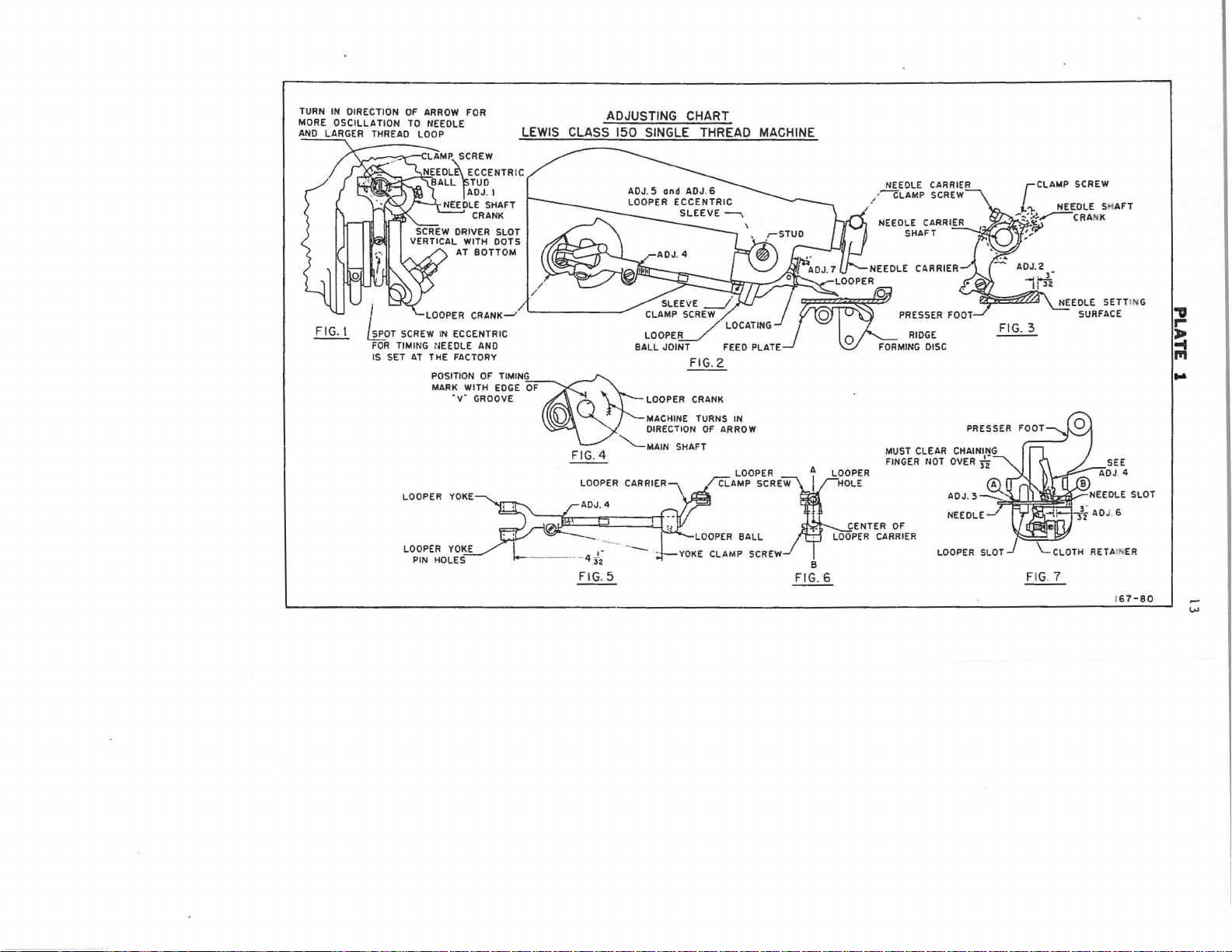
ADJUSTING CHART
CLASS 150
SINGLE
THREAD MACHINE
FIG. I
I
'-LOOPER
koT
SCREW
FOR
TIMING NEEDLE AND
IS SET
AT
LOOPER
LOOPER
PIN
CRANK-J
IN
ECCENTRIC
THE FACTORY
POSITION
MARK
OF
TIMIN~
WITH
EDGE
·v·
GROOVE . LOOPER CRANK
YOKE
YOKE
HOLES--
OF
[)
,-4
~
FIG.4
LOOPER
.
"-.._MAIN
0
FIG. 5
ADJ. 7
U"-NEEDLE
.
SLEEVE
___
CLAMP
LOOPE!L_/
BALL JOINT FEED PLATE Q
j)..l_j'
SCREW
/ Q PRESSER FOOT
/ LOCATING
~OOPERO
7flr:J:
FIG.2
---
MACHINE TURNS
DIRECTION
SHAFT
!
;;
~LOOPER
;t-YOKE
IN
OF
ARROW
LOOPER A LOOPER
CLAMP
SCRE):I
BALL
CLAMP
SCREW
HOLE
• CENTER
·
LOOPER
B
FIG. 6
NEEDLE CARRIER
__-
----cLAMP
NEEDLE CARRIER
FORMING
CARRIER
SCREW
SHAFT
~'/·.·"f?l
CARRIER
RIDGE
DISC
MUST CLEAR CHAINING
FINGER
!lOT
OVER
ADJ. 3
OF
CLAMP SCREW
[
·-
~~r-CRANK
/
ADJ. 2
-'
.,..;,·
II
).•
3Z
FIG. 3
PRESSER
E
FIG. 7
NEEDLE SH
NEEDLE SET TING
SURFACE
RETAINER
AFT
1
67-BO
"D
r"'
~
Ill
...
...,
LEWIS
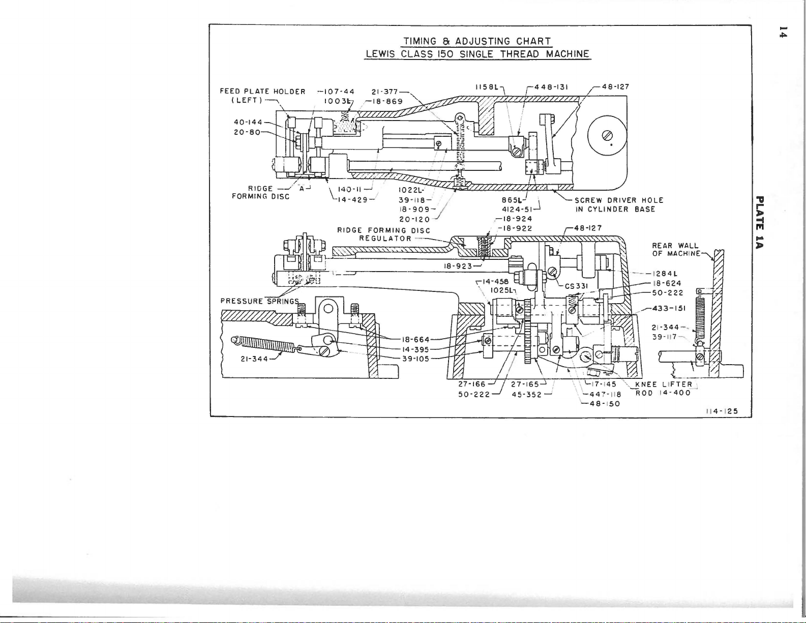
TIMING a ADJUSTING
CLASS
150 SINGLE THREAD MACHINE
CHART
-
~
FEED
PLATE
(LEFT)----.._
40-144
20-80
HOLDER
RIDGE
FORMING
REGULATOR----
39-118-
1
8-909-
20-120
DISC
18-664
14-395
39-105
~48-127
,
!i:
;;:
...
)It
\\ '-17-1
45
\~::~;~~
'-..,
KNEE LIFTER
~
ROD 14-400
114-1
25
15
Crank
Lifter
14-395
forming disc
in
best
Collar
and
Collar
14-429.
Collar
press
the
justing
Adjustment
holding
TIMING
Needle:
justing
following
Shaft
knee
THE
A
the
To
chart).
48-150
position
39-105
setting
and
feed
1284
39-117
14-400
lifter
M1\CHINE
No. 4 taper
needle
2
position.
secure
steps
Plate
for
tension
plates
is
and
for
out
of
the
must
1.
is
for
operator.
is
used
of
used
is
used
setting
contact
point
correct
be
taken
adjusting
for
Spring
to
sewing
for
to
with
needle
adjustment
taking
21-344
taking
take
tension
should
and
the
posit ion
up
for
position.
up
end
up
end
of
Spring
depressing
be
for
settings
end
thrust
returning
thrust
thrust
lever.
used
the
made.
of
the
of
of
21-344
when
needle
(See
of
Shaft
ridge
Shaft
knee
ad-
swing
ad-
Knee
for
when
the
hand
wheel,
over
until
straight
1.
With
carrier
point
setting
screw.
Adjustment
slot -See
Loosen
carrier
needle
clear
Check
clamp
of
the
surface.
the
-See
will
the
to
To
needle
screw
up
and
the
To
Figure
needle
just
needle
see
set
is
the
followmg
driver
down with
machine
screw
needle
See
3
set
Figure
clear
shoulder
that
the
at
is
the
7 -
carrier
the
point
the
steps
slot
in
the
and
1/16
Figure
needle
the
following
2 -
the
setting
of
the
extreme
in
the
two
above
move
11
to
3/32"
3.
in
clamp
in
or
needle
of
presser
for
needle
end
must
the
dots
position,
the
Tighten
the
screw
out
so
slot
tile
of
be
needle
at
needle
from
correct
steps
that
at
foot
needle
in
the
its
taken:
eccentric
the
carrier
the
the
position
and
and
the
"A"
at
correct
stroke
Turn
bottom.
loosen
edge
needle
setting
move
rear
-See
"B"
point
towards
the
ball
See
the
needle
so
that
of
the
carrier
in
the
must
the
needle
side
F i
gure 7 -and
about
still
is
position
machine
stud
Figure
the
needle
clamp
needle
be
of
the
.005".
1/16"
the
is
made:
16
to
3/32"
the
needle
LOOPER
importance.
-
allow
1/64"
carrier
must
remove
-See
be
understood
or
from
the
carrier
The
correct
(See
adjustmg
The
looper
space
Figure 2 -and
replace
The
looper
needle
clamp
setting
is
between
in
case
this
carrier
setting
screw.
of
chart).
mounted
looper
the
for
assembly.
assembly
surface
the
in
correct
any
looper
Plate
the
looper
shoulder
assembling
reason
consists
of
is
1.
it
presser
of
the
carrier
and
end
is
necessary
of:
foot.
greatest
assembly
of
looper
of
this
Tighten
unit
to
sembling
positively
screw.
that
the
est
the
looper
looper
and
which,
Adjustment
side
Adjustment
side
6.
or
or
yoke,
for
when
when
Looper
Clamp
Looper
Looper
The
these
located
The
looper
distance
will
The
reference
4
Means
the
5
Means
the
Yoke -in
Screw
Ball
Carrier
looper
parts
on
from
ball,
be
looper
for
looper
for
needle
carrier
into
the
shaft
carrier
the
to
the
4-1/32".
has
to
the
adjusting
is
adjusting
is
which
and
the
machine.
of
is
assembled
edge
side
of
See
means
drawing,
the
taking
the
between
are
looper
the
of
the
the
adjusting
for
looper
the
looper
the
the
Now,
looper
looper
looper
the
are
loop
prongs
looper
yoke
are
the
carrier
to
the
yoke
ball
chart-
following
numbered
position
from
the
position
of
yoke
pin
set
before
looper
by a spot
looper
pin
hole
nearest
Figures
adjustments,
as
follows:
on
the
needle.
on
the
the
looper.
ball
yoke
to
right
left
holes
as-
is
so
near-
the
5
hand
hand
Adjustment
to
right
Means
or
6
right
for
to
adjusting
left.
the
position
of
the
looper
from
left
17
Adjustment
must
be
6
and
the
Z
and
3.
TIMING
the
two
set
turn
the
wheel
towards
slot
in
the
with
the
chine
which
ure
4.
7
Means
Before
in
accordance
needle
The
THE
LOOPER
Timing
screws
machine
needle
two
dots
There
will
There
for
setting
setting
looper
the
on
over
the
rear
eccentric
at
the
is a "V"
be
at
is a timing
adjusting
the
looper,
with
instructions
must
is
and
can
looper
the
by
the
is
looper
the
hand
of
the
ball
bottom -See
notch
top
mark
the
looper
be
as
be
relative
crank.
wheel
machine
stud
cut
of
the
on
in
the
looper
for
described
timed
until
is
Figure
in
the
shaft.
the
at
to
To
by
straight
main
looper
and
out.
carrier
Figure 5 and
in
adjustments
only
one
the
needle.
time
the
turning
the
1,
the
screw
up
and
adjustment
shaft
crank -See
assembly
Figure
place.
Loosen
looper,
hand
driver
down
of
the
1,
1.
ma-
Fig-
crank
coincides
shaft.
minus
chine
ADJUSTING
following
here
loop
the
eye
needle.
relative
with
given:
from
point
and
This
steps
of
the
Turn
timing
Clamp
the
two
AND
To
secure
The
the
needle.
The
this
point
the
looper
with
mark
to
the
the
set
SETTING
should
looper
position
prong
of
the
the
left
will
edge
looper
screws.
the
correct
be
is
first
for
3/3Z"
long
crank
of
crank
THE
taken
the
from
prong
until
hand
edge
not
vary
the
"V".
to
LOOPER
adjustment
and
adjusted
long
the
just
the
more
the
in
the
as
prong
inner
clearing
of
main
the
timing
the
"V"
than
of
same
looper
of
the
end
mark
on
l/3Z"
shaft
the
looper,
sequence
looper
of
the
the
the
of
the
is
needle
scarf
on
the
main
plus
ma-
the
as
taking
is
to
of
or
the
have
the
18
men
ts
top
of
slowly
of
the
To
arc
Turn
the
hand
until
needle.
secure
taken
the
and
the
wheel
long
this
made:
hand
will
prong
setting,
wheel
be
moved
of
in
the
the
following
clockwise
away
looper
from
is
over
steps
direction;
the
operator
the
and
that
center
adjust-
is,
very
line
the
4,
Figures 2 and
the
looper
permits
rightment
ner
just
clamp
clamp
tion,
passing
ing
chaining
the
these
tion
the
not
prong
the
looper
short
the
and
6,
until
end
of
clears
screw
screw -See
until
chaining
1/32" -See
finger,
previous
should
until
the
looper
enter
the
will
looper
eccentric
prong
Loosen
just
clears
Loosen
looper
slide
the
the
needle
Check
the
scarf
-See
Continue
the
short
Figure
adjustments
be
re-made.
Continue
short
slot
in
looper
clear
eccentric
clears
the
5 -
the
eccentric
the
long
to
see
Figure
Figure
to
prong
finger,
or
if
to
prong
the
the
sleeve
the
looper
and
the
sleeve
looper
prong
eye.
that
of
the
rotate
7.
the
rotate
foot.
slot
edge
sleeve-
edge
yoke
roll
scarf
clamp
eccentric
of
point
needle.
5,
2.
the
of
the
if
foot
If
the
clearance
have
the
of
the
If
in
the
of
the
the
least
of
clamp
the
looper
of
the
screw
sleeve
and
the
Adjustment
the
the
hand
looper
has
short
not
hand
looper
foot,
looper
amount
the
to
looper
of
the
Tighten
looper
chaining
is
been
short
adjust
looper
screw -See
until
the
long
needle.
-See
F i
gure 2 -this
be
moved
sleeve -Figure
is
long
wheel
is
at
prong
greater
correctly
wheel
has
prong
slot
6,
possible
slot.
3/32"
prong
the
eccentric
in
clockwise
nearest
finger,
does
than
in
clockwise
passed
of
so
that
in
the
Figure
from
from
looper
not
made, and
the
the
the
foot
so
Adjustment
prong
left
Z,
adjust-
the
of
the
yoke
sleeve
direc-
point
not
exceed-
clear
1/32",
direc-
edge
looper
short
by
moving
Z.
Move
that
the
of
to
in-
looper
when
the
then
of
does
the
crotch
the
prongs
until
instead
ing
corrective
the
of
of
the
point
Care
looper
of
the
Continue
of
so
doing
steps
must
looper.
the
be
when
to
turn
needle
strikes
are
taken
the
needle
the
should
the
required:
now
hand
crotch
as
should
wheel
enter
the
of
the
needle
be
entering
in
clockwise
between
looper -the
may
the
strike
between
direction
prongs
the
but
follow-

19
Figure
the
needle
er,
clearing
the
two
-
Figure
5,
Figure
distance
tighten
tion
until
center
prong
needle
of
must
tenth
SETTING
ment
cerned,
threads
However,
ding
silks
of
ser
er
Figure
direction
to
of
the
needle.
be
paragraphs
4,
or
and
the
needle
foot -Figure
position
the
needle
Loosen
4,
and
does
The
In
prongs
z,
and
Z,
from
the
sleeve
Continue
the
line
of
the
and
that
corrected -this
THE
Figure
The
is
now
may
these
hemming
cotton,
by
l -
the
towards
the
turn
crank
not
needle
the
two
case
the
-to
turn
until
the
the
needle.
clamp
point
of
the
needle.
looper
the
point
In
case
inclusive
LOOPER".
5.
Do
machine,
ready
cause a slight
adjustments
the
however,
11
l/16
from
3,
re-adjusting
timing
the
resulting
two
strike
must
prongs
needle
correct
the
prongs
to
rotate
the
is
3/3Z"
the
not
as
to
sew.
more
instead
dots
hand
in a larger
set
slightly
the
enter
about
this,
looper
When
screw
long
Check
from
of
the
above
is
done
under
Be
turn
far
variation
will
heavy
it
the
of
the
on
wheel
screws
in a clockwise
crotch.
between
an
should
loosen
eccentric
of
the
looper
this
-See
the
hand
prong
to
the
long
conditions
as
the
sure
the
looper
as
the
Different
give
materials.
may
be
needle
3/3Z",
needle
the
ball
to
thread
on
the
Tighten
equal
not
enter
the
sleeve-
setting
Figure
wheel
of
the
see
that
inner
prong
described
heading
to
roll
eccentric
looper
material
from
the
best
advisable
setting
without
ball
stud
obtain
loop.
looper
the
amount.
sleeve
are
has
direction
the
prongs
about
about
been
crank-
set
clamp
Adjustment
z.
in a clockwise
looper
just
do
the
the
surface
stud
should
slightly
is
the
point
end
of
eye
clears
not
exist,
in
the
"ADJUSTING
looper
and
needle
or
above
results
When
hemming
to
set
on
changing
-Adjustment
be
more
See
until
screws.
of
the
loop-
midway
screw
an
equal
made,
direc-
over
the
of
the
of
the
the
scarf
they
fifth
to
AND
-Adjust-
sleeve.
are
different
adjustments.
when
pad-
the
point
the
pres-
the
loop-
turned
in
throw
of
long
con-
1,
RETAINER
presser
needles
firmly
ing
no
the
loop
foot
as
hold
material.
will
OR
The
Cloth
must
possible
the
form,
CLOTH
Retainer
at
and
work
H
the
resulting
all
on
CLAMP
times
set
relative
to
the
work
in
located
be
adjusted
disc
is
carried
missed
in
to
while
stitches.
the
the
along
a·s
ridge
the
cloth
close
needle
with
opening
to
forming
is
the
of
the
disc
penetrat-
needle,
the
to
20
Part
No,
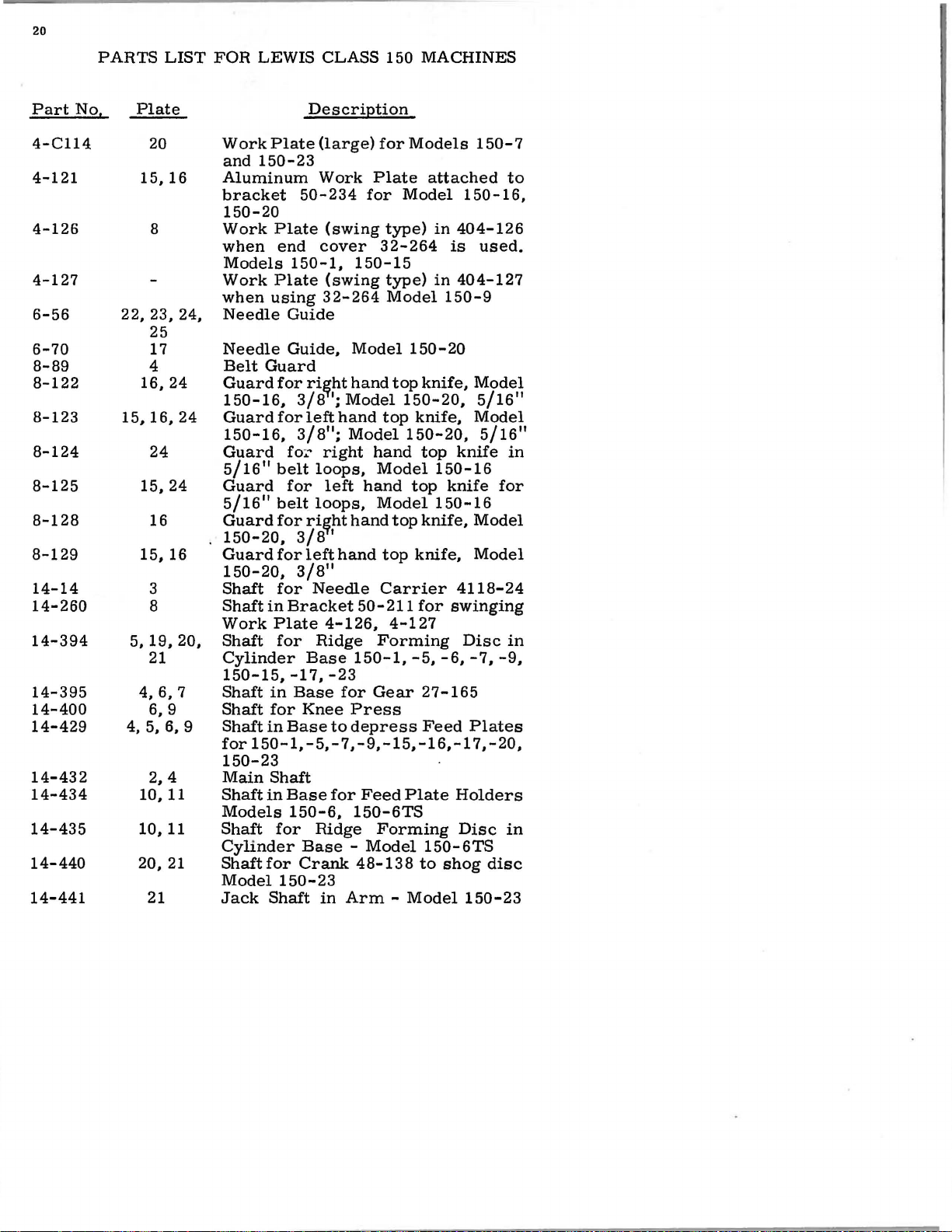
4-C114
4-121
4-126
4-127
6-56
6-70
8-89
8-122
8-123
8-124
8-125
8-128
8-129
14-14
14-260
14-394
14-395
14-400
14-429
14-432
14-434
14-435
14-440
14-441
PARTS
Plate
15,
22, 23, 24,
16,24
15,16,24
15,
15,
5,
4,
4, 5, 6, 9
10, 11
10,
20,
21
LIST
20
8
25
17
4
24
16
3
8
19,
21
6,
6, 9
2, 4
16
24
16
20,
7
11
21
FOR
LEWIS
CLASS
150
Description
Work
and
Aluminum
bracket
Plate
150-23
50-234
(large)
Work
for
Plate
for
150-20
Work
when
Models
Work
when
Needle
Needle
Belt
Guard
150-16,
Guard
150-16,
Guard
5/16
Guard
5/16
Guard
150-20,
Guard
150-20,
Shaft
Shaft
Work
Shaft
Cylinder
150-15,
Shaft
Shaft
Shaft
for
Plate
end
Plate
using
(swing
cover
150-1,
(swing
32-264
type)
32-264
150-15
type)
Model
Guide
Guide,
Model
Guard
for
ri~ht
hand
Model
top
Model
hand
Model
hand
Model
hand
top
Carrier
50-211
4-127
Forming
150-1,
Gear
Press
depress
top
top
for
fo
11
belt
for
11
belt
for
for
for
in
Bracket
Plate
for
in
for
in
Base
1
3/8
left
11
3/8
:;.
~
right
loops,
left
loops,
ri~ht
3/8
I
left
11
3/8
Needle
4-126,
Ridge
Base
-17,
-23
Base
Knee
to
;
hand
;
hand
for
150-1,-5,-7,-9,-15,-16,-17,-20,
150-23
Main
Shaft
Models
Shaft
Cylinder
Shaft
Model
Jack
Shaft
in
Base
for
150-6,
for
Ridge
Base -Model
for
Crank
150-23
Shaft
in
Feed
150-6TS
Forming
48-138
Arm -Mode1150-23
MACHINES
Models
150-7
attached
Model
150-16,
in
404-126
is
in
404-127
used,
150-9
150-20
knife,
150-20,
knife,
150-20,
top
Model
5/16
Model
5/16
knife
150-16
top
knife
150-16
knife,
knife,
Model
Model
4118-24
for
swinging
Disc
-5, -6, -7, -9,
27-165
Feed
Plate
Plates
Holders
Disc
150-6TS
to
shog
disc
to
11
11
in
for
in
in
Part
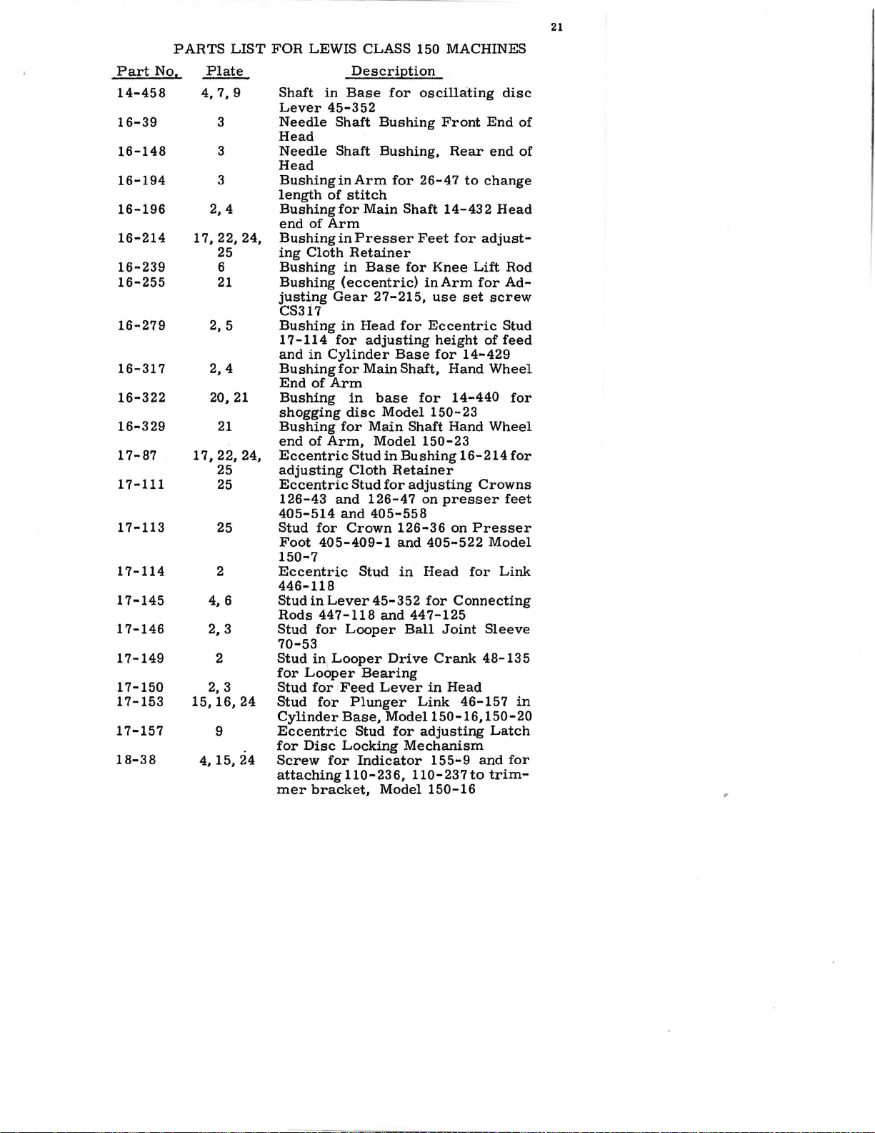
14-458
16-39
16-148
16-194
16-196
16-214
16-239
16-255
16-279
16-317
16-322
16-329
17-87
17-111
17-113
17-114
17-145
17-146
17-149
17-150
17-153
17-157
18-38
PARTS
No,
LIST
Plate
4, 7, 9
3
3
3
2, 4
17,
22, 24,
25
6
21
2, 5
2, 4
20,
21
21
17,22,24,
25
25
25
2
4, 6
2, 3
2
2,
3
15, 16,
24
9
~1~24
FOR
LEWIS
Shaft
Lever
Needle
Head
Needle
Head
Bushing
length
Bushing
end
of
Bushing
ing
Cloth
Bushing
Bushing
justing
CS3i7
Bushing
1
7-114
and
in
Bushing
End
of
Bushing
shagging
Bushing
end
of
Eccentric
adjusting
Eccentric
126-43
405-514
Stud
for
Foot
150-7
Eccentric
446-118
Stud
in
Rods
Stud
for
70-53
Stud
in
for
Looper
Stud
for
Stud
for
Cylinder
Eccentric
for
Disc
Screw
attaching
mer
bracket,
CLASS 150 MACHINES
Description
in
Base
45-352
Shaft
Shaft
in
Arm
of
stitch
for
Main
Arm
in
Presser
Retainer
in
Base
(eccentric)
Gear
27-215,
in
Head
for
adjusting
Cylinder
for
Main
Arm
in
base
disc
for
Main
Arm,
405-409-1
Lever
447-118
for
Stud
Cloth
Stud
and
126-47
and
405-558
Crown
Stud
Looper
Looper
Bearing
Feed
Plunger
Base,
Stud
Locking
Indicator
110-236,
Model
45-352
for
oscillating
Bushing
Bushing,
for
Base
Model
in
Retainer
for
and
and
Drive
Lever
Model150-16,150-20
for
Model
Front
Rear
26-47
Shaft
14-432
Feet
for
for
Knee
inArm
use
for
Eccentric
height
for
Shaft,
Bushing
126-36
in
Ball
Mechanism
Hand
for
14-440
150-23
Shaft
Hand
150-23
adjusting
on
presser
on
405-522
Head
for
Connecting
447-125
Joint
Crank
in
Head
Link
adjusting
155-9
110-237
150-16
End
end
to
change
Head
adjust-
Lift
for
set
screw
of
14-429
Wheel
Wheel
16-214
Crowns
Presser
Model
for
Sleeve
48-135
46-157
Latch
and
to
trim-
21
disc
of
of
Rod
Ad-
Stud
feed
for
for
feet
Link
in
for
,
22
Part
No,
18-70
18-71
18-74
18-CllO
18-121
18-125
18-C186
18-261
18-270
18-277
18-281
18-292
18-295
18-307
18-318
18-326
18-330
18-345
18-355
18-375
18-391
18-400
18-416
18-492
18-493
18-500
PARTS
17,
22, 23, 25
12, 18,
2,13,14
17,
LIST
Plate
3
2
3
13,
14
8
11
13,
14
13
22, 24
8
23
10,
11
3,
17
19,
21, 25
6
25
4
16
3,
15
16
22,
24,
25
2
6
9
FOR
LEWIS
Clamp
Clamp
Spot
carrier
Screw
50-223
405-538,
Screw
s·
crew
Set
ing
Screw
Screw
Screw
Screws
110-230
and
Screw
presser
Bearing
base,
Screw
ket
150-16,
Screw
44-275
base,
Screw
knee
Screw
for
150-15
Screw
405-514,
Screw
regulator
Screws
3/8
Screw
4124-56
Screws
3/8
Screw
eccentric
Spot
Screw
Set
stud17-157
CLASS
Screw
Screw
Screw
4118-15
for
to
presser
in
for
Screw
folders,
for
in
in
work
for
to
150-6TS
for
feet
Screw
Models
for
50-160,
-20
for
to
Models
for
lift
shaft
for
bracket
for
for
for
inch;
for
and
for
inch
in
Screw
for
Screw
Description
for
for
in
479-8
attaching
Models
shaft
14-260
Spring
for
collar
Models
attaching
end
of
plate
attaching
presser
holding
for
150-6
holding
and
attaching
plunger
150-7
clamping
in
cover
50-223,
presser
405-522,
107-51
in
cylinder
top
44
7-97-1
knives,
150-20,
Model
447-23,
top
knives,
bushing
stud
17-87
for
eccentric
70-28
in
base
150
MACHINES
needle
looper
to
feet
405-497,
150-9
21-332
39-C255
150-9,
1733 L
eccentric
for
roll
feet,
chaining
feed
and
presser
for
ridge
26-152
and
39-117
base
of
32-107
Models
foot
405-558
ridge
base
in
head,
Model150-16
16-214
in
sleeve
for
locking
carrier
yoke
locate
folder
and
150-15
for
work
Model
150-15
to
stud
holding
forming
Models
plate
150-6TS
foot
22-
25 7,
forming
in
150-23
arm
on
head,
405-409-1,
forming
Model
5/16
Model
for
presser
433-93
for
knee
4118-
449-27
on
looper
bracket
405-537,
150-6TS
for
locat-
50-280
17-
folders
150-6
fingers
in
cylinder
to
bracModel
cylinder
collar
screw
150-9
150-16,
inch
screws
150-20,
holding
foot
in
press
eccentric
24
plate
L
87
plate
to
disc
to
and
disc
in
head
Part
PARTS
No.
LIST
Plate
FOR
LEWIS
CLASS
150
Description
23
MACHINES
18-561
18-565
18-602
18-622
18-623
18-624
18-628
18-643
18-644
18-647
18-657
18-662
18-664
18-674
18-700
18-701
18-702
18-715
18-732
18-737
18-738
18-744
18-749
20
2
15
13
22
4
7.
8
17,22.23.
25
2
7
13.
14.
15.
17.24
2
2.
4.
7
2
2. 4. 21
5
3
15
2
2
2. 15
25
9
Screw
Model
Screw
Screw
for
150-23
for
in
limitlength
Screw
for
150-9
Screw
ser
Screw
inder
Screws
and
Screw
for
Foot
for
Base
for
21-375
for
Foot
Screw
Screw
inder
Screw
Models
for
Screw
Sleeve
Screw
Base
bottom
Screw
for
for
Base
for
150-9
Plate
for
70-53
to
to
of
in
Head
Spot
Screw
Eccentric
Spot
Screw
in
Cylinder
Hex
Head
Crank
Screw
under
Screw
Screw
in
Screw
Yoke
Model
Knurled
48-105
for
Head,
for
for
Head
for
449-27
150-16
Screw
Presser
Screw
for
4124-55
Aluminum
Stitch
of
stitch
Folder
Cloth
Retainer
Eccentric
Feed
Needle
40-151
Spring
Clamping
and
110-295.
clamping
in
hold
Head
Arm.
and
Cylinder
Stitch
for
433-144
for
Base
Spot
Screw
in
Knife
Model
Feed
Looper
Pin
and
for
Feet
adjusting
Ball
Head
Regulator
Model
Spring
433-151
Plate
Guide
in
Arm
Link
Folders
150-15.
Model
Looper
Head
to
Bracket
Base
Regulator
Ridge
in
Arm
Pivot
for
Head
Drive
150-16,
Driving
Shaft
for
22-8
holding
adjusting
Crank
Joint
Cover
149-16
150-16.
21-385,
Stop
Springs
on
46-148
Screws
150-16
Adjusting
Arm,
149-16
Forming
Bearing
Needle
Link
150-20
Crank
in
17-153
Crowns
48-150
in
Base.
-20
Model
on
Pres-
in
Cyl-
21-75
Presser
in
Cyl-
to
Foot.
Cylinder
50-222
Disc
117-41
Drive
46-155
48-135
Looper
to
(2)
to
in
in
on
24
PARTS
LIST
FOR
LEWIS
CLASS
150
MACIDNES
Part
No.
18-750
18-750
18-751
18-757
18-764
18-766
18-767
18-869
18-870
18-872
18-892
18-895
18-900
18-906
18-909
18-C911
18-918
18-919
18-920
18-921
18-922
18-923
Plate
10,
*
3
21
4
3
2, 3
5
5, 6, 9
5,
13,
5
5
5
20
5
14
4,
12,
19
6,
9,
5, 9
5
4
4
11
16
18, . Taper
20
Screw
150-6
Screw
Hex
Eccentric
Hex
150-23
Screw
release
Screw
447-97-1
Screw
lever
Pivot
140-11
Hex
connect
Base
Shoulder
Holders
Stop
of
Hinge
on
Screws
Cylinder
Flat
4-C 114,
Screw
Cradle
Base
Screw
Foot,
Cylinder
Hex
48-151
Flat
top
Flat
Plate
Adjusting
to
Adjust
height
for
and
for
Screw
Screw
on
hole
for
for
in
Head
Bearing
and
Shoulder
Cranks
in
Screw
Cylinder
Screws
top
of
Cylinder
for
Head
to
for
140-11
for
Model
Bearing
Base
Clamp
in
Head
of
Cylinder
Head
110-224
adjust
Screw
that
Description
Cylinder
150-6TS
75-212,
in
Stud
17-114
for
448-139
top
of
cap
Joint
in
clamping
140-12
Screw
Bearing
Cylinder
for
Regulator
Base
for
cap
Base
Screws
Bracket
adjusting
and
Hemmer
150-15
Screws
Screw
Base
of
Screw
Base
Screws
on
Screw
depth
in
disc
Base
Model150-5
Link
Screw
can
446-118
arm
of
large
Head
Stud
in
in
48-127
Screws
Base
regulator
Base
of
ball
to
fasten
spring
140-12
Bracket
for
for
Crank
Arm
for
42-25
for
top
of
in
Regulator
of
Needle
18-922
be
Cover,
in
Head
in
Base,
to
plug
ball
17-150
for
Disc
Cylinder
Link
and
for
Feed
149-28
Handle 7 6-
joint
Work
tensions
in
on
Feed
48-150
and
Regulator
Cylinder
Penetration
Screw
raised
Models
to
clamp
Model
tension
end
for
Cradle
Base
46-164
48-150
Plate
on
4124-51
Plate,
Cylinder
Presser
Plates
97-17
Dial
Base
107-51
to
limit
of
feed
to
in
top
12
in
for
in
and
on
Part
P
ARTS'LIST
No.
Plate
FOR
LEWIS
CLASS
Description
150
MACHINES
25
18-924
18-934
18-937
18-939
18-941
18-942
18-943
18-951
18-952
18-955
18-956
18-957
18-974
18-1031
20-31
20-34
20-35
20-60
20-79
20-80
20-120
20-122
20-129
20-142
21-58
21-63
21-75
21-193
4, 5
*
13,
14
8, 20
19,
20
12,
18,
18,19,20,
21
17
15,
16,
*
16
16,
*
*
*
*
9, 20,
3
*
5, 12
5
12,21,25
7, 8
*
17
23
4, 7, 8
17,
22,24
19
24
24
21
Set
Screw
in
place
Screw
Shoulder
Models
Hex
50-211
Screw
in
Shoulder
Holder
Shoulder
Rod
Screw
Models
Bearing
Base,
Screws
Flathead
Plates
Screws
5/16
Screw
Screw
Nut
Nut
Nut
ing
150-23
Nut
Nut
ing
Nut
on
Nut
ing
Nut
Base,
Adjusting
Feed
Adjusting
Tension
150-16,
Spring
Foot
Springs
Spring
Feet
Screws
Base,
47-119,
11
for
for
for
for
for
Pin
on
on
Plunger
length
for
Shaft
to
Disc
for
Models
Plates
for
for
Models
adjust
for
in
Regulator
32-292,
Bearing
150-9,
and
for
Model150-23
Bearing
99-303,
for
150-16,
Screw
for
Model
for
411868-21
Screw
22-254
head
locking
in
in
Plunger
Spring
150-20
for
150-15
for
50-227
Crank
Bearing
Model
adjusting
for
150-
holding
Bearing
150-16
Top
thread
48-141
15
18-7
inCylinder
to
426-47
of
stitch
Cylinder
pressure
Cylinder
150-7
nuts
Nut
for
for
Retainer
Feed
Cloth
Model150-9
Screw
Work
48-138
Screw
Models
Screw
150-23
150-20
Plunger
16,
machine
Screws
Knives,
guide
Model
49
and
adjust
in
Ridge
Base
Base
26-152
and
for
applying
68-21
lower
4137-126
Plate
Retainers
to
lock
for
and
150-20
Table
to
for
150-7
for
Knife
150-
Model
41-48
150-16,
Nut
Base,
thread
head
Forming
of
Ridge
in
150-23
Knives,
Holders
18-923
Feed
Plate
Brackets
Shog
Feed
and
Connecting
Pressure,
in
20
for
for
tension
on
on
Disc
Plate
150-23
Cylinder
to
Bench
Feed
150-16,
150-20
for
Bear-
Model
tension
chang-
Disc
Form-
Cylinder
Model
Presser
Presser
to
26
Part
No.
21-213
21-240
2
1-243
2
1-250
2
1-251
2
1-C269
21-C269-1
21-274
21-300
21-332
21-341
21-344
21-348
21-357
21-375
21-377
21-385
21-422
21-426
22-8
22-9
22-149
22-152
PARTS
Plate
12,
6, 7
10,
4,21
LIST
2
25
25
8
8
14
.....
~
·
9
5
11
21,
16
25
5
13
:.~
*
2
25
2
11
25
FOR
LEWIS
Spring
lator
Spring
Feet
150-23
Spring
Feet
Long
P in
Short
Pin
404-126
Hemmer
405-497
431-150
Hemmer
431-147,
Spring
Disc
Spring
ing
Disc
Base
Spring
tolocate
Base,
Spring
Forming
150-7
(See
Spring
in
Base
Spring
through
Spring
150-7
Heavy
Model
Spring
Folder
Model
Thread
Tension
Pin
for
Pin
for
and
for
Taper
Spring
Cylinder
CLASS
150
MACHINES
Description
for
Ball
149-16
for
in
cloth
79-31
Head
Retainer
in
Stitch
405-514,405-556,405-558,
for
Adjusting
with
Spring
Spring
22-189
when
and
431-148,
for
for
Regulator
on
Eccentric
Model
for
Disc
and
Crown
on
on
in
Spring
431-159
Spring
Latch
Ball
Ridge
150-6TS
Plunger
in
150-23.
Screw
Bracket
Bracket
Work
on
using
Model
51-21
79-31
Forming
33-150
Cylinder
Plate
Presser
Folders
for
in
on
top
26-152
For
150-15
for
Ridge
Disc
Base,
heavy
21-357)
for
of
Finger
Folder,
(heavy)
and
Spring
150-6
for
Spring
Collars
Arm
150-23
for
and
Cradle
39-117
for
starting
Model
for
Feed
150-6TS
in
for
150-16
26-152,
Plate
Cylinder
Folder
150-9
Nipper
Release
Looper
Needle
Crown
Pin
Pin
for
for
Spring
Plunger
Yoke
Carrier
126-36,
locating
Feed
Spring
449-27
4118-24
Model
Head
Plate
Base
Regu-
on
Presser
Model
on
Presser
50-211
50-211
Assembly
431-149,
Folders
Locking
Form-
of
Cylinder
44-269
in
Cylinder
for
Ridge
Models
Spring
and
39-105
material
Models
Holder,
Base
431-175,
in
Head
in
150-7
on
Arm
Holders
for
for
Foot
head
in
27
Part
22-189
22-248
22-249
22-254
22-255
22-256
22-257
22-262
22-263
22-271
22-286
22-314
23-216
23-217
23-225
23-301
23-310
23-311
24-263
24-264
24-265
24-266
24-270
24-272
No,
PARTS
Plate
8
11
5
21
6
6, 7
17
17
20
4. 5
17
*
2.
10,
22. 23,
23, 25
14,
15.
13,
13,
4, 22
4,
12.
18,
21,
12. 19,
25
10, 11.
14.
LIST
u.
23
24
23
23
22
25
23
FOR
Spring
taining
Pin
handle
Forming
Stop
Disc
inder
Bearing
Base,
SpringPin
21-344
Spring
21-344
Pin
Knives.
Spring
Pin
150-23
Pin
Pin
Knives,
Automatic
Feed
150-5, 150-6,
25
Feed
150-17
Feed
Feed
Feed
Seams
Feed
Seams
Feed
150-5,
Feed
150-5,
Feed
19.
150-23
Feed
21.
and
Feed
23
150-6,
Feed
150-15
LEWIS
Description
Pin
Swing
in
Eccentric
45-345
Disc
Pin
in
Regulator
Base
Pin
Model
in
Cylinder
Pin
in
Crank
Model150-16,
Pin
for
for
Spring
for
Spring
in
Crank
Model
3/32
3/32
1/16
for
Model
3/32
Pitch
3/32
Pitch
Plate
150-17
Plate
150-17
Plate
Plate
150-23
Plate
150-6TS
Plate
CLASS
in
Bracket
Work
to
in
107-51
149-28
for
150-23
in
Collar
in
Base
48-141
21-58,
21-344
21-377
48-141
150-20
Tension
Pitch
150-6TS,
Pitch
Pitch
150-16
for
for
(left)
(right)
(left)
(right)
for
for
roll
for
roll
150
MACinNES
50-211
Plate
33-150
operate
Model
for
48-138
Base
Release
for
for
for
Model
Model
for
for
for
404-126
150-6TS
Ridge
on
in
39-117
of
Arm
for
driving
150-20
Model150-16,-20
in
Arm.
in
Base
for
driving
Models
150-7
Model
Model
150-9,
150-9,
Models
Models
Models
Models
padding.
hemming.
for
and
Step
Forming
top
of
Cylinder
for
Spring
for
Spring
Pin
150-1,
150-23
150-15
150-1,
150-1,
150-7
Models
Model
Re-
Lever
Ridge
Cyl-
lower
Model
lower
and
1/4"
3/8"
and
150-7
28
Part
No.
24-277
24-278
24-294
24-295
24-300
26-47
26-152
26-160
27-76
27-165
27-166
27-215
30-52
30-68
30-C258
32-106
32-107
32-208
32-210
32-225
32-229
32-262
32-264
32-292
PARTS
Plate
16,24
16,24
13,23
13,
12,18,21,
15, 16,
20,
18,
15,
):
~
3
25
24
4
4
20,
3
13
14
2
2
11
10
12
2
8
4
16
LIST
23
17,
21
21
FOR
LEWIS
Feed
150-16
Feed
150-16
Feed
Feed
Feed
Plunger
stitch.
Plunger
44-275,
Plunger
Model
Gear
27-215,
Gear
Forming
Gear
Forming
Gear
Needle
Spring
Clamp
Foot,
Cover,
Cover
Cover
End
150-6TS
End
150-6
Cover
150-7
Cover
Model
Cover,
Cover
150-1,
Cover
Description
Plate,
Plate,
Plate,
Plate,
Plate,
in
(See
for
Models
for
150-16,
on
Main
Model
(large)
Disc
(small)
Disc
for
Shagging
Clamp
Clamp
for
Hemmer
Model
Aluminum,
Plate
32-106
Cover
Cover
for
end
and
150-23
for
150-16,
Aluminum,
for
End
150-5,
for
Top
CLASS
Ri
ght
Left
Model
Model
Model
Arm
426-47)
holding
Node
150-20
Shaft
150-23
for
in
for
in
for
150-15
(rear)
for
for
of
Cylinder
Bottom
150-20
of
150-9,
of
150
Hand
Hand
150-9,
150-9,
150-20
for
adjusting
Ridge
150-7
in
for
rolling
Base
rolling
Base
Disc,
Folder
Spring
for
for
Aluminum
Cylinder
Cylinder
of
Bracket
for
Cylinder
150-15,
Arm
MACHINES
Side,
Side,
1/4
3/8
Model
Model
11
Seams
11
Seams
length
Forming
and
150-23
Cylinder
driving
back Ridge
of
Arm
back
of
Arm
Model
150-23
Model
on
Presser
Head
Base,
Base,
Base,
Model
Model
Models
50-234,
Head
Base,
Models
150-17
of
Disc
Base,
gear
Ridge
150-9
Head

29
Part
33-149
33-150
34-31
34-48
35-21
36-16
39-87
39-92
39-95
39-99
39-105
39-117
39-118
40-26
40-38
40-57
40-60
40-63
40-126
40-144
40-148
40-151
40-154
PARTS
No.
LIST
Plate
2
11
*
20, 21
4
3
*
2, 4, 8
16,24
6
4, 7
6
5,
16
20
*
19
3
17
2
5
5
2
14
FOR
LEWIS
Eccentric
length
Eccentric
Ridge
stitching,
Automatic
Cam
Cam
Model
Roll
back
Arm
Looper
Stop
Collar
Table
Collar
Cylinder,Base,
Spacing
of
Collar
Thrust
of
Collar
14-394,
Washers
Bracket
Washer
75-212
Slap
Fiber
Fiber
Joint
Lock
Washer
Forming
SpacingWasherfor
448-131
Washer
Shaft
Washer
Holder
150-15
Forming
for
for
Ridge
Collar
Arm
Arm
Washer
slap
under
Washers
in
CLASS
Description
for
of
stitch
to
Model
Tension
Shagging
150-23
turning
Forming
in
Head
on
Main
404-126
for
Plunger
Collar
on
Shaft
Collar
on
Ridge
414-449
for
Screw
50-227
for
pants
on
Cylinder
for
washer
slap
washer
head,
for
Nut
Disc
in
Cylinder
on
Eccentric
Arm
between
99-298
150
MACHINES
Feed
in
adjust
Disc
and
Model
on
14-395
on
to
4124-55,
Model150-16,
on
20-80
Shaft
Feed
in
Lever
Head
44-270
150-6TS
Release
Ridge
Gear
Disc
Shaft,
Plunger
Link
150-16,
Shaft
Shaft
Forming
in
feed
Cylinder
14-440
in
14-400
Cylinder
18-939
machine
bottom
Base,
on
Ball79-28
for
screws
in
in
Ball
Base
433-144
Plate
27-165,
to
adjust
supplementary
for
through
Pin
Raising
Forming
in
Swing
Stud
Base
Disc
for
Edge
Model
Model150-23
4124-56
end
Cylinder
79-9
24-27 2 and
Base
Disc,
to
in
base
Work
Gear
17-153
150-20
in
of
in
Shafts
Base
attaching
Guide
150-5
in
Head
150-20
in
Head
of
Ridge
Base
in
Crank
on
Main
Model
roll
Base
Arm
Base
Ball
of
in
 Loading...