

Page 1
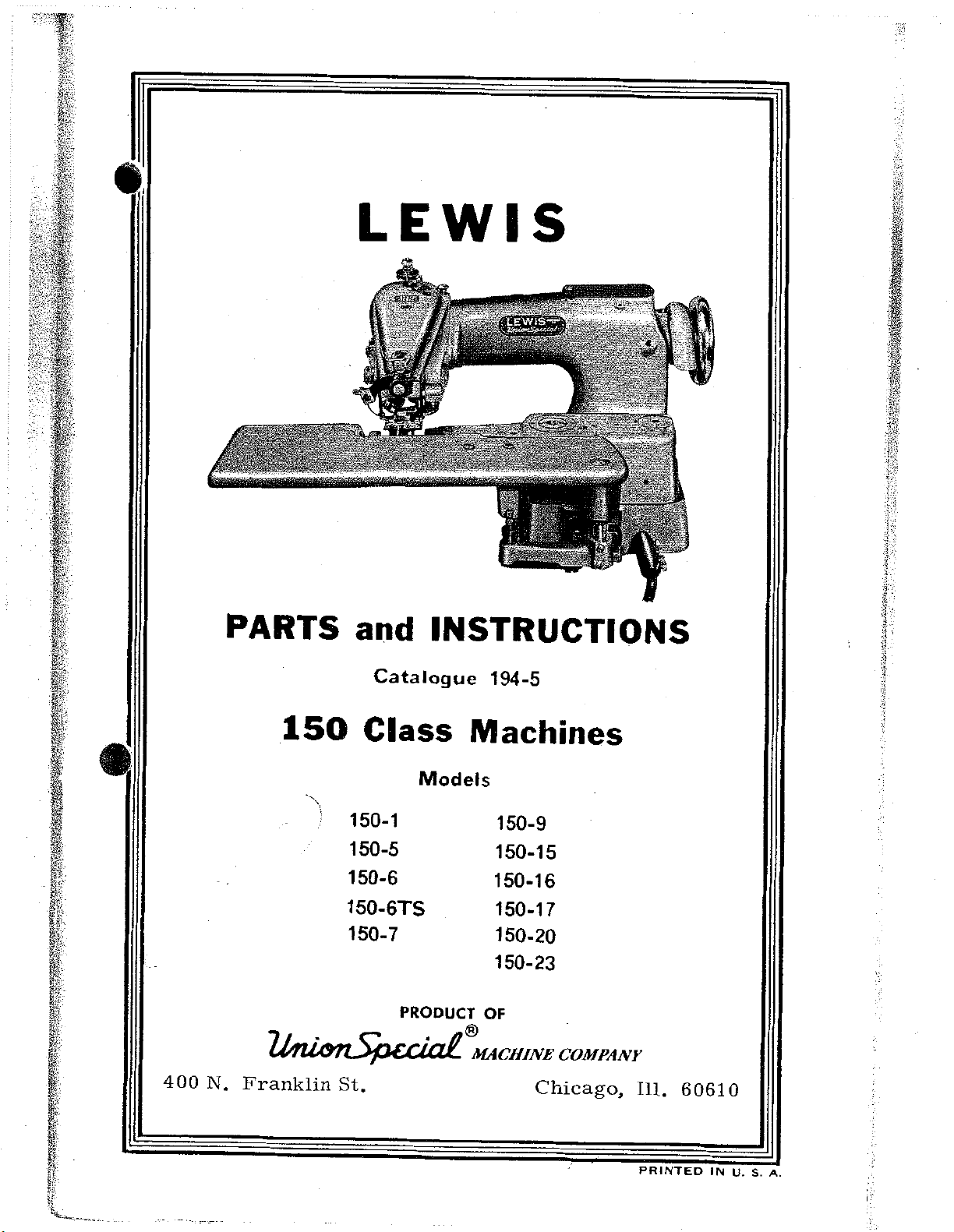
•
LEWIS
PARTS and INSTRUCTIONS
400
N.
Catalogue
150
ll/J"ZU.m.Jl;.ic.c:':I.Q.:£.
Franklin
Class Machines
Models
150-1
150-5
150-6
150-6TS
150-7
PRODUCT
St.
194-5
150-9
150-15
150-16
150-17
150-20
150-23
OF
®
MACHINE
COMPANY
Chicago,
Ill.
60610
PRINTED
IN
U.
S.
A.
Page 2
1
•
Adjusting
Adjusting
Belt
Cylinder
Feeds
Flared
Feed
Feed
Loop
Loops
••••.•
Plates
Plate
LEWIS
Chart
Looper
Parts
••
. . . . . . . . . . . . . . . . . . . . .
Base
•
. . . . . . . . . . . . . . . . . . . . . . .
. . . . . . . . . . . . . . . . . . . . . . .
for
3/8"
Parts
and
CLASS
INDEX
and
5/16"
their
150
Adjustments.
. . . . . . . . . . . . . . . . . . . . . . . . .
Skirts.
. . . . . . . . . . . . . . . . . . . . . . . . .
.•
Holders.
. . . . . . . . . . . . . . . . . . . . .
MACHINES
wide
PAGE
13,
14
16-19
93,94
12
11,114
11
115
116
•
Folders
General
Hemming
Plate
Feed
Instructions
Instructions
Instructions
Instructions
Model
Model
Additional
Plates
........
Instructions
8.
Plates ..•.....
Numbers
150-1
for
Flared
Parts
for
Belt
-
General •..••
for
Ordering
for
Using
and
.•
. . . . . . . . . . . . .
Parts
Model
.
Skirts:
to
adjust
Serial
for
150-1
. . . . . . . . . . . . . . . . . . . .
•••
. . . . .
Parts
pressure
.,
.................
Loop
Machine
Parts
Catalogue
Model
•.•...•
Numbers
..
. . . . .
for,
See
of
. . . . . . . . . . .
a •
. . . . . . . . . . . . .
. . . . . . . . . . . .
••
,
150-1
. .
. .
11 7
7-19
.
11,
5 3
91,92
7-19
5
5
5
44-54
54
46-53,110
Model
Additional
See
150-5
Plates
•.••••.•••••.••
Parts
for
for
Model
Model
150-1
150-5
•••••
. .
. .
.
.....
56
56
46-53,110
Page 3
2
Model
Additional
Instructions
Plates
Model
Additional
Instructions
Plates
Model
Additional
Instructions
Plates
Model
Additional
Plates
150-6 ..............
150-6TS
150-7
150-9
Parts
for
for
Model
••••••••.••••..
Parts
for
for
Model l 50-6TS
.•....
Parts
for
for
Model
..•....•.....
Parts
for
Model
LEWIS
for
Model
150-6
for
Model
.........••
for
Model
150-7
for
150-9.
CLASS
INDEX
Model
150-6
•••••••••
Model
150-6TS
Model
150-7
•••••••
Model
150-6
•••••
150-6TS
•••••••
150-7
•••
150-9
•
150
MACHINES
.
•
•
. . . . . .
. .
•
. .
. .
. . .
. . .
..
PAGE
58-60
60
57
59,
111
61-65
64,65
61
63,111
66-71
70,
71
67,68
•
69,113
72-76
75-76
74,111
•
•
Model
Additional
Plates
Model
Additional
Instructions
Plates
Model
Additional
See
Model
Model
Additional
Instructions
Plates
150-15
150-16
150-17
Plates
150-20
150-23,
for
for
for
.••.••••.••...•.
Parts
Model
Parts
Model
Parts
for
for
150-15
................
for
for
Model
150-16
..........•.....
for
Model
Model
••••••••
Model
150-16
••••••••••
Model
150-1
150-15
150-16
. . . . . .
150-1
••••••
•
. . .
. . . . .
.
••••••
. . . .
7 •
. . . ....
. . . . . . .
. . . . . .
. .
. . .
•
.....
. . . . . . . . . . . . . . . . . . . . . . . . . .
Parts
Model
for
for
Model
150-23
Model
150-23
.••••••
150-23
. .
. .
. .
•
. . .
. .
. . .
77-80
80
79,111
81-93
86-90,93
91-92
82-85,112
96
97
46-53,111
81-94
98-109
106-109
98-100
102-105,113
•
•
Needles
Oiling
Parts
. . . . .
Machine
List
including
. . . . . . . . . . . . . . . . . . . . . .
e • • e e e e • e e e e • e O e e O • 0 e • e e e
all
Models
. . . . . . . . . . . . . .
8
9
20-43
Page 4
3
LEWIS
•
Plate
Presser
Regulating
Ridge
Ridge
Retainer
Speed
Serial
Numbers
Forming
Forming
of
Numbers
-
See
Feet .........
Length
Disc
Disc
or
Cloth
Machine
Clamp
•••••
and
Models.
of
Stitch
. . . . . . . . . . . . . . . . . . . . .
Regulator
Model
CLASS
INDEX
.
• • • • • • • • • • • • • • • • 0
See
150
MACHINES
below
•••••••••
. . . . . . . . . . . . . . . . . .
..
. . . . . . . . . . . . . . .
• • • • • • • • • • • • •
Cl
• • • • •
. . . . . . . . . . . . . . . . . . .
Numbers.
. . . . . . . . . . .
PAGE
9,118,119
12
9,10,120
10
19,20
9
5
•
Thread
Threading
Timing
Unpacking
•••••••.
Machine
and
Adjusting
Machine
. . . . . . . . . . . . . . . . . . . . . . .
.......
Charts.
•••••••
. . . . . . . . . . . . . . . .
. . . . . . . . . . . . . . . .
. . . . . . . . . . . . . . . .
13,
8
7
14
7
Page 5
4
PLATE
NO.
1
IA
2
3
4
5
6
7
8
9
10
11
12
13
14
15
16
17
18
19
20
21
22
23
24
25
LEWIS
T
irning
T
irning
Parts
Parts
Parts
Parts
Parts
Parts
Parts
Parts
Additional
Additional
l
50-6TS
Additional
Additional
Additional
Additional
Additional
Additional
Additional
Additional
Additional
Additional
Additional
150-1
Additional
150-6, 150-9,
Additional
Additional
150-7
Chart
Chart
For
For
For
For
For
For
For
For
and
and
CLASS
.••••••
•••••••
Model
Model
Model
Model
Model
Model
Model
Model
Parts
Parts
•••.••......••.•.••••.
Parts
Parts
Parts
Parts
Parts
Parts
Parts
Parts
Parts
Parts
Parts
150-5
Parts
Parts
Parts
150-23
150-1
150-1
150-1
150-1
150-1
150-1
150-l
For
For
For
For
For
For
For
For
For
For
For
For
For
For
150-15
For
For
150
INDEX
PLATES
150-1
Model
Models
Model
Model
Model
Model
Model
Model
Model
Model
Model
Model
Models,
•.••••••••••
Models,
and
Model
Models,
• • • • • • • • • • • • • • • •
MACHINES
. . . . . . . .
. . . . .
. . . .
. . . . . . . . . . . . .
. . . . . . . . .
. . . . . . . . . . . . .
. . . . . . . . . . . . .
. . . . . . . . . . . . .
150-6
150-6,
150-7
150-9
150-15
150-16
150-16
150-16
150-23
150-23
150-23
150-23
150-17
150-16
••••••
••••••
••••••
•••••
•••••
•••••
•••••
. . . . .
. . . .
•••••
••••
PAGE
NO.
13
14
46
47
48
49
50
51
52
53
59
63
69
74
79
33
84
85
102
103
104
105
110
111
112
113
•
Page 6
-~-
'
5
•
The
in
compiling
used
class
under
machine
show
in
150
Additional
each
To
the
INSTRUCTIONS
TO
Model
the
Machines.
find
for
page
The
of
Model
the
Model
model
150-1
this
a
which
machine.
catalogue
150-1,
parts
number.
part
the
number,
No.
FOR
ORDER
Machine
are
used
needed,
is
to
part
referring
located
USING
PARTS
is
the
that
used
is
is
in
make
note
wanted,
to
on
CATALOGUE
basic
the
all
each
model
the
top
of
machine
majority
the
models
Model
number
and
the
model.
the
head
of
of
are
listed
on
index
used
parts
the
the
will
•
***************************************
The
in
Turn
obtain
part
to
section
referred
at
is
the
The
the
Serial
arm
No.
under
of
each
the
machine
top
cover.
is
stamped
***************************************
State
when
part
common
Model
ordering
to
the
number.
bottom
parts
are
to
the
at
No.
plate
to
Model
of
the
listed
additional
the
bottom
and
parts.
showing
If
part
page
and
Serial
cannot
150-1,
of
parts
plate
parts
of
page
No.
drawings
orto
drawing
used
of
of
be
the
listed.
parts
machine
of
machine
located,
model
in
each
over
the
listed.
then
referred
model
models
to
the
If
part
for
description
January,
number
and
1971
is
best
known
plate
turn
for
to
General
locating
part.
parts
list
Page 7
6
such
standard,
plates,
subjects:
as
presser
22, 23,
The
see
plate
lists
24,
drawings
feet,
on
and
folders
last
25.
show
and
pages
Refer
only
etc.
of
catalogue,
to
index
the
For
standard
parts
also
for
following
parts
other
see
than
Feeds.
Feed
Folders.
Presser
Ridge
Plates.
Feet.
Forming
Disc.
•
•
.)
•
Page 8
7
•
GENERAL
ADJUSTMENT,
UNPACKING
To
and
remove
position.
blocks
the
the
sure
fore
ment
box
parts
dust,
are
box.
other
very
The
small
to
look
destroying
that
carefully
project
Set
especially
INSTRUCTIONS
MACHINE
remove
the
nails
Use a nail
held
goes
by
knee
parts
carefully
it,
with
beyond
up
the
from
AND
150
the
machine
and
puller
nails
lifter
so
to
machine;
will
through
that
the
avoid
the
the
or
machine.
FOR
OPERATION
MACHINES
from
screws
to
screws
is
attached
be
you
breaking
head
looper.
avoid
found
the
will
of
the
clean
that
THE
OF
the
hold
breaking
driven
to
the
wrapped
material
find
all
Lift
the
the
machine.
away
INSTALLATION,
LEWIS
box,
the
the
through
side
in a package.
used
the
machine
tension
accumulated
take
brace
machine.
of
the
for
parts
studs
CLASS
the
out
off
the
blocks
outside
box,
packing
and
equip-
of
as
these
lint
cover
in
These
of
and
Be
be-
the
and
•
Place
with
machine,
knee
for
pad
the
the
the
transmitter,
lift
lever
Mark
the
screw
under
three
packing
HAND
away
at
the
THREADING
let
just
on
the
through
the
needle
through
machine
WHEEL
The
from
pitch
From
back
left
the
the
The
the
case.
top
the
line
of
side,
tension
bar,
eye
the
machine
machine
is
1/2"
the
three
holes;
machine
bolts
rim
operator
of
the
the
spool
the
tension
then
then
of
the
and,
should
from
bore
and
that
of
or
belt
lift
discs;
through
needle.
on
assemble
the
holes
the
fasten
were
hand
clockwise.
groove.
stand,
disc,
thread
then
the
the
be
edge
for
hole
wheel
pass
then
over
through
hole
bench
the
set
the
for
the
used
turns,
with
knee
on
the
of
the
machine
the
belt;
machine
to
hold
The
the
thread
between
the
pin
the
in
the
the
lift
table
table.
to
when
pulley
the
which
pig-tail
needle
pulley
lever
so
screws
place
the
the
machine
facing
is
through
tension
passes
clamp,
to
that
and
the
table,
the
2"
eyelet
lined
f.elt
diameter
the
up
the
the
bore
using
into
pulley,
eye-
disc
over
then
Page 9
8
REMOVING
plates
will
signs
changes
NEEDLE
by
Taper
Not
29-492 1 /2
and
break
at
any
on
number:
Point
Scarfed
WORK
See
that
retract
the
We
reserve
time
machines
SIZES
The
the
the
thread.
without
needles
needle
disc
the
previously
are
Taper
0
15
is
and
right
incurring
furnished
Front
29-343
29-343
29-344
29-344
out
of
the
give
the
to
change
the
manufactured.
in
the
Point
Scarf
½
½
cloth.
work a quick
specifications
obligation
following
Lower
to
15°
the
jerk
or
install
sizes,
Sharp
Front
29-493
29-493
29-494
29-494
feed
which
ti
de-
such
order
Point
Scarf
½
½
Ordinarily,
purpose.
to
meet
righted
THREAD
cotton
either
REGULATING
the
cylinder
showing
turn
and
dial
for
the
to
A
all
Use
word
Use
thread
"00"
The
the
raising
word
obtain
sizes
full
range
requirements.
ONLY
"LEWIS"
any
in
or
"000".
DEPTH
needle
base
word
"Less
less
genuine
good
sizes
penetrating
of
the
"More"
the
ridge
II
needle
which
29-343
of
needle
stamped
grade
70
to
OF
NEEDLE
machine
and
forming
penetration
sizes
LEWIS
on
of
left-twist
100.
indicates
If
adjustment
and
indicates
½
and
29-344
are,
needles.
the
silk
PENETRATION
is a dial
disc
the
in
however,
shank
three
thread
is
the
direction
for a deeper
direction
the
work.
will
Look
of
each
cord
is
located
with
serve
available
for
the
needle.
hard
used,
graduations,
to
select
on
top
in
which
penetration;
turn
the
the
copy-
finish
of
to
Page 10
-1'
1
9
•
SKIPPING
Examine
over.
stitches.
REPLACING
and
needle
IMPORT
SPEED
3000
recommended
Speed
Replacing
Insert
tighten
guide.
ANT
The
stitches
may
STITCHES
point
needle
NEEDLE
needle
set
screw.
--
OIL
LEWIS
per
minute.
in
starting
be
increased
of
needle
will
generally
into
needle
Needle
MACHINE
Class
to
a
150
A
new
suit
speed
to
see
carrier
should
DAILY
machines
of
machine
operator
if
remedy
bear
can
1800
or
or
it
is
blunt
skipping
as
far
as
slightly
be
operated
to
2000
with a new
class
or
possible
on
the
stitches
of
work.
turned
of
up
to
is
operator.
•
TIMING
screws.
PRESSER
ble
and
foot
up
.010"
needle
RIDGE
slot
in
150-17.
in
play
justing
first
tension.
guide
in
the
relation
question.
to
be
All
basic
FOOT
Place
with
or
down
FORMING
The
For
Before
the
the
loosened
new
the
Observe
freely.
disc
presser
to
the
other
cradle
pivot
driving
needle
point
so
that
DISC
must
foot,
needle,
models,
setting
140-11.
bearing
and
parts
in
directly
the
point
that
(Refer
be
adjusted
and
Models
the
screw
the
tension
the
shank
so
refer
disc
Any
are
needle
over
of
of
to
Plate
that
150-1,
to
be
end
18-869,
of
properly
carrier
the
needle
the
needle
needle
lA)
to
be
the
nose
150-6,
special
sure
play
Set
Spring
timed
passes
in
the
of
instructions
that
there
can
be
Screw
21-377
as
far
guide
is
under
center
the
disc
150-6TS,
is
taken
1003
released.
with
as
adjust
scant
over
of
no
up
must
spot
possi-
the
the
the
is
set
150-7,
on
end
by
ad-
model
Page 11
10
Adjust
cradle
hand,
1003
setting
even
loosen
crank
disc
slot
needle
disc
the
disc
1158
set
the
shaft.
Pivot
must
then
to
lock
Adjust
is
with
To
set
448-131
so
that
in
presser
will
joins
in
crank
collar
when
the
the
is
Screw
move
lock
18-869
tension
end
adjust
screw
when
be
periphery
at
its
448-131
to
pivot
the
of
the
and
the
foot
1/16"
most
take
18-869
very
screw
in
spring
end
nut
disc
1022
set
point
and
from
up
just
freely.
in
place.
21-377
of
screw
20-120.
to
in
collar
disc
advanced
and
at
of
all
to
of
center
where
the
set
end
enough
Check
place
for
center
slot,
the
disc.
position.
screw
play
by
with
adjusting
of
39-118
at
needle
of
the
the
small
This
1022
in
to
take
by
moving
tightening
nut
slot
in
and
the
same
is
at
disc,
radius
setting
Tighten
in
the
ridge
up
20-120.
tensions
the
presser
clamp
time
the
the
collar
play
cradle
forming
set
Normal
screw
set
center
point
on
nose
is
made
clamp
39-118
but
screw
the
by
18-909
foot,
1158
the
of
the
of
the
of
when
screw
and
disc
is
the
•
m
hand
shaft
ling
engages
nut
RIDGE
Base
needle
The
less
be
ulator
raised
ridge
side
feed
the
20-80
word
depth
of
To
plate
and
remove
disc,
the
and
FORMING
The
raises
penetration
"More"
of
The
in
forming
in
the
the
remove
holder,
the
care
slot
in
tighten
DISC
dialed
and
lowers
indicates
needle
regulator
order
disc.
"More"
regulator.
the
ridge
remove
washer
must
the
regulator
in
to
be
disc.
firmly.
REGULATOR
the
the
work
penetration.
also
protect
The
adjustment
direction
forming
the
40-144
taken
Assemble
located
ridge
being
more
limits
the
as
nut
and
that
the
{Refer
on
forming
done
depth,
the
needle
is
far
as
disc,
20-80
disc.
key
the
top
disc
to
and
amount
point
made
possible
depress
on
When
in
washer
to
Plate
of
the
to
form
"Less"
that
from
by
the
end
of
flange
40-144
Cylinder
get
a
blind
the
striking
turning
to
stop
left
disc
reassemb-
107-44
and
lA)
the
correct
stitch.
indicates
disc
the
pin
can
the
reg-
in-
6,
.,)
•
A
with
disc.
the
needle
needle
guide
must
and
be
point
in
the
of
needle
needle
carrier
over
the
and
ridge
in
contact
forming
Page 12
•
and
adjust
the
ridge
ridge
.010"
assemble
place.
hexagon
sure
ed
more
FEED
loosening
over
lowest
allel
weight
low
in
of
front
the
with
the
forming
which
tension
Now
remove
screw
forming
is
the
18-924
These
headed
ridge
machine,
point,
materials;
presser
The
of
The
the
the
two
forming
cylinder
and
two
then
bottom
the
18-923
disc
disc
will
equivalent
screw
screws
adjusting
adjustment
in
reverse
feed
is
binding
away
set
the
of
for
foot
about
set
that
shaft
lift
the
to
two
and
are
screw
for
disc
is
base,
adjustable
heavy
screws
from
feed
the
turn
direction
presser
work,
3/64".
screw
contacts
is
mounted
needle
thicknesses
set
located
18-922.
the
spring
made
in
relative
holding
you,
until
so
that
the
18-924
the
cradle
and
off
of
tightly
inside
tension
by
turning
clockwise
for
to
the
the
it
is
foot,
for
feed
(See
adjust
the
of
to
of
less
the
feed,
feed
1/32"
light
must
lock
Plate
140-11
so
needle
newspaper.
screw
the
main
for
correct
nut
20-120,
direction
tension.
presser
and
motion
below
and
be
brought
No.
lA)
in
which
that
the
guide
Re-
18-923
locat-
to
get
foot
turning
is
at
and
par-
medium
11
in
pres-
by
the
be-
•
inch.
FEED
of
the
springs.
from
material
the
paper
applied
feed
slightly
moving
looper,
in
The
PLATES
The
presser
There
moves
resulting
Check
before
For
for
each
the
fullness
on
the
feed
·Feed
foot
when
with
point
sewing
feed
hem.
is
and
must
the
to
see
of
adjustable
Plates
feed,
be
needle
the
needle,
in
skip
that
needle
flared
plate
in
this
press
when
enough
penetrates
stitches.
Feed
penetrates
skirts
can
type
from
the
on
pressure
a
loop
Plates
with
be
varied
of
hem
three
work
its
to
against
feeding
applied
the
material,
will
not
clamp a piece
material.
wide
so
the
if
the
eight
the
stroke
to
be
formed
hems,
machine
operator
stitches
bottom
by
hold
for
of
the
pressure
holds
two
the
if
the
for
news-
will
per
work
back
Page 13
12
ADJUSTING
located
open
on
per
which
hand
slot
serve
the
es
CYLINDER
Plate
ate
the
position
the
timing
are
on
the
the
shaft,
inch,
will
wheel
to
lengthen
through
feed
per
inch,
the
ridge
disc
bracket
marks
Eccentric
top
disc
lA)
to
with
LENGTH
The
stitch
top
of
the
cover
with
press
engage a slot
over
as
is
BASE
The
forming
insert
Parts
spot
50-222.
that
of
numerals
down
and
stitch,
the
opening
you
directly
PARTS
parts
and
in
the
screws
must
433-151
OF
is
regulated
arm
the
the
away
and
turn
under
in
the
disc,
remove
Cylinder
Parts
match
and
STITCH
of
the
machine,
machine
which
feed
knob
in
the
feed
from
in
until
AND
and a timing
you
toward
the
top
the
the
THEIR
Cylinder
depress
the
Base
assembled
the
Gear
27-165.
by
the
to
observe
indicate
located
mechanism;
while
you
to
of
the
numeral,
indicator.
ADJUSTMENT
Base
the
feed
work
from
where
mark
in
timing
knob
near
the
on
holding
shorten
arm,
indicating
and
plate
the
possible
has
this
mark
426-47,
the
the
feed
number
top
of
now
the
stitch,
the
base
and
machine.
been
bracket
in
the
head.
indicator·
the
turn
knob
number
the
{See
of
arm
retract
are
milled
that
bracket
Plate
First,
of
stitches
machine,
the
in
and
stitch-
opera-
held
have
3,
the
ob-
on
in
in
•
'..,
.
"
removing
Rod
447-118
18-664
bearing
Shaft
assembling,
all
to
adjust
sing
of
feed
14-429
against
lA.
far
48-127
and
Stud
14-458
coincide,
feed
cylinder
plates
so
the
Be
sure
as
possible,
turns
Bracket
Stud
take
Gear
by
if
Crank
the
Crank
plates.
base.
in
that
contact
Check
17-145
from
bracket
865
out
27-166
the
the
the
machine
448-131
ridge
48-127
The
contact
two
feed
plttes
the
and
without
50-222
which
Lever
Spot
gear
forming
Loosen
thicknesses
surface
turn
45-352.
from
of
the
and
Screws
teeth
will
is
is
adjustment
screw.CS
with
are
above
over
interfering
can
be
will
the
hole
Eccentric
are
function
clamped
disc.
for
adjusting
presser
of
of
feed
in
contact
setting
hand
removed
disconnect
Next
base
in
Ball
433-151
1025
and
engaged
properly.
to
(See
Plate
is
made
331
foot,
newspaper
plate
by
depressing
wheel,
with
adjacent
from
remove
by
slipping
Joint
18-624,
so
the
disc
Shaft
through
in
crank
adjust
holders.
with
and
the
the
end
the
4124-51.
are
that
shaft
lA)
14-429
48-127
surface
will
bottom
the
see
parts.
machine
of
Connecting
three
the
headless
held
on
therefore
the
timing
and
for
a
hole
(A)
just
pinch
See
(A)
of
presser
feed
that
crank,
Screws
to
when
marks
is
used
depresin
front
and
with
of
plate
plates
by
the
•
foot.
as
Page 14

TURN
MORE
AND
IN
DIRECTION
OSCILLATION
LARGER
THREAD
•
OF
ARROW FOR
TO
NEEDLE
LOOP
AMP
SCREW
EEDL1ECCENTRIC
BALL
~
TUD
ADJ. t
NEEDLE SHAFT
CRANK
LEWIS CLASS 150 SINGLE THREAD MACHINE
ADJUSTING CHART
ADJ. 5
and
LOOPER
ADJ. 6
ECCENTRIC
SLEEVE-,
NEEDLE
/--CLAMP
I
CARRIER
SCREW
,~/,.--
"
[
-=-
,.
/
~ftt>
/
CLAMP
NEEDLE
•
SCREW
SHAFT
CRANK
FIG. 1
I
1
koT
FOR
IS
'--LOOPER
SCREW
TIMING NEEDLE AND
SET
AT
THE
LOOPER
LOOPER
PIN
CRANK_/
IN
ECCENTRIC
FACTORY
POSITION
MARK WITH EDGE
"V"
OF
TIMING
GROOVE
YOKE
YOKE
HOLES-
~
~
=
-----
-----
BALL
FIG.4
LOOPER CARRIER
ADJ, 4
1
j
-----
,
..
----
32
4
FIG. 5
LOOPER
JOINT
FIG.2
LOOPER
MACHINE TURNS
DIRECT!ON
MAIN SHAFT
!
-;,:f--voKE
CRANK
OF
rt-LOOPER
CLAMP SCREW
FEED
IN
ARROW
LOOPER
CLAMP
BALL
PLATE
SCREW
A
.,,--HOLE
8
FIG. 6
FORMING
MUST CLEAR CHAINING
LOOPER
CENTER
LOOPER CARRIER
FINGER
OF
RIDGE
DISC
NOT
OVER
ADJ. 3
LOOPER
FIG. 3
PRESSER
1
~,
3
SLOT
FIG. 7
NEEDLE
SURFACE
~DJ.4
SETTING
SEE
NEEDLE
RETAINER
167-80
"g
...
~
"'
""
SLOT
w
Page 15
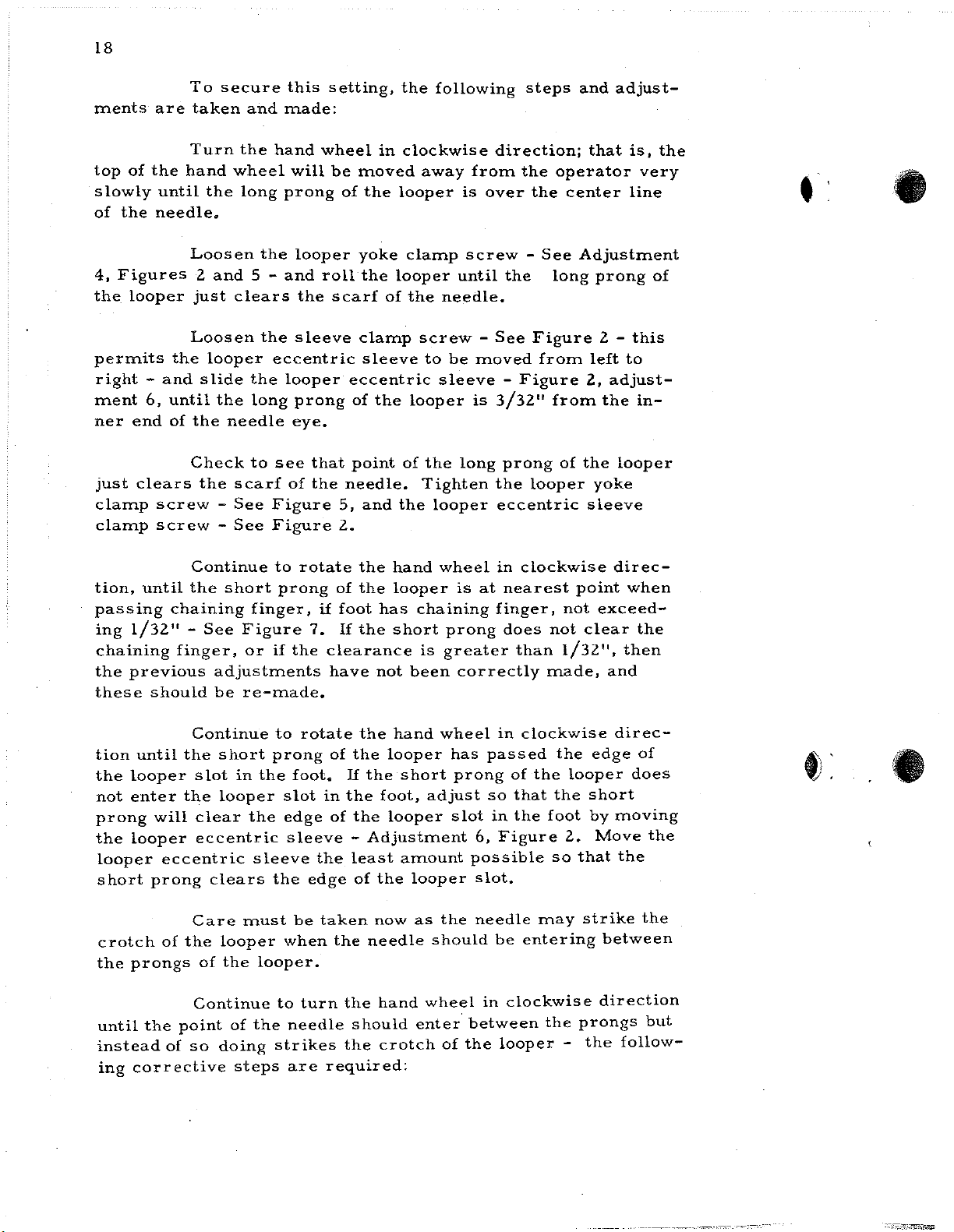
TIMING
LEWIS CLASS 150 SINGLE THREAD MACHINE
8r
ADJUSTING
CHART
,i,.
-
FEED
PLATE
(LEFT)-~
40-144
20-80
RIDGE
FORMING DISC
HOLDER
--107·44
I003t·
..
,1
'
~!
'
/
_J
'i,_'.J
_,;:ii
,--n1=1ni!hi'51.
I
1/.::0,
1
~~
.PJtJ
\ 140·11
\...14·429_/
RIDGE
ic;t~
I,
,;;-
r.-·1:_
21·377-
___J
FORMING
REGULATOR----
---v5tf-
102
39·
18·90920-120-
I8·664-----M
14
-39-105-
2L-
118-1;,
DISC
-3
9 5
· '
1
..
~--i
II58L,
865L.J
4124-51.J
_,-18·924
-18·922
448·131
'
SCREW
IN
CYLINDER
48-127
k=,r{,
,~--
4 8 -127
0
DRIVER
BASE
---I284L
--50-222
l-~----433-I51
HOLE
REAR WALL
OF
MACHINE
18
• 6 2 4
21-344-.
39·117·,.
,,
~
-I
,,,
...
>
•
•
50·222
~
NEE
ROD
LIFTER_j
14-400
--,"·---
..
•
• 12 5
•
.
....
A
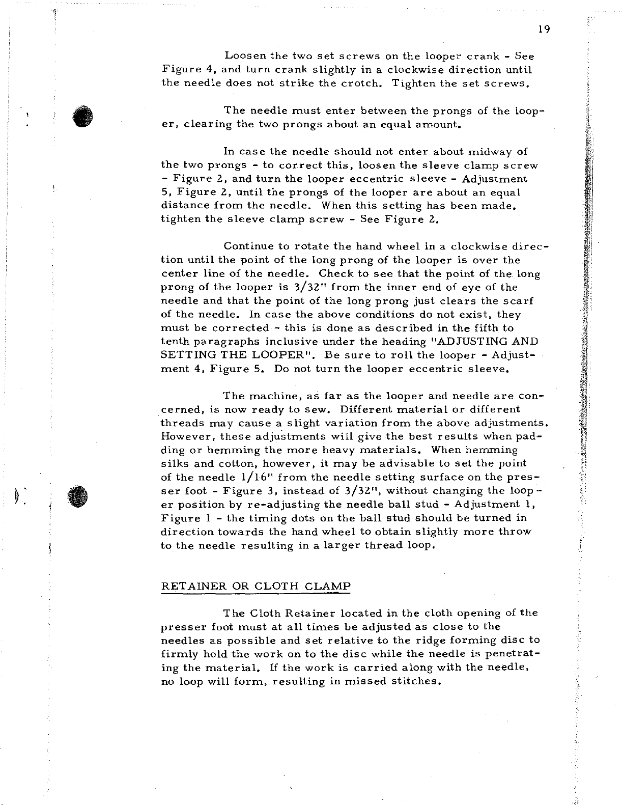
Page 16
15
Lifter
14-395
forming
14·-429.
press
holding
TIMING
Needle:
justing
in
best
and
disc
Shaft
knee
THE
the
Crank
position
Collar
setting
and
Collar
Collar
14-400
lifter
MACHINE
A
No. 4 taper
needle
48-150
39-105
tension
feed
1284
39-117
and
out
pas
it
is
for
is
plates
is
used
is
for
of
contact
point
ion.
for
adjusting
operator.
used
of
Spring
to
sewing
for
used
setting
needle
for
taking
to
take
tension
with
the
taking
21-344
position.
up
up
depressing
should
position
up
for
end
end
of
Spring
be
end
thrust
returning
thrust
thrust
lever.
used
of
the
of
of
of
knee
21-344
when
Knee
Shaft
ridge
Shaft
for
ad-
•
the
following
justing
Adjustment
when
hand
over
straight
1.
carrier
point
setting
screw.
Adjustment
slot -See
Loosen
carrier
needle
clear
Check
chart).
the
wheel,
until
with
of
surface.
the
will
the
to
To
2
To
needle
the
screw
up
and
the
clamp
the
To
Figure
needle
-
See
just
needle
see
secure
steps
Plate
set
the
is
follow
driver
down
machine
screw
needle
See
3
set
the
Figure.
clear
shoulder
that
the
must
point
at
the
mg
with
in
and
is
1/16"
Figure
needle
7 -
the
carrier
2 -
the
setting
correct
be
I.
steps
slot
the
the
taken
of
the
extreme
must
in
the
the
two
above
moye
following
in
needle
of
to
3/32"
3.
in
clamp
or
presser
for
the
Tighten
the
out
adjustment
and
settings
needle
end
of
be
taken:
needle
dots
at
pas
it
ion,
needle
from
correct
steps
screw
so
that
slot
at
"A" -See
foot
the
needle
in
the
its
eccentric
the
loosen
carrier
the
the
needle
position
and
and
move
the
at
point
for
the
made.
correct
stroke
Turn
bottom.
edge
setting
rear
"B"
about
needle
towards
the
ball
the
so
of
carrier
in
must
the
side
Figure
still
{See
position
machine
stud
See
needle
that
the
needle
the
needle
needle
of
.005".
is
1/16"
swing
ad-
the
is
Figure
the
clamp
be
rnade:
the
7 -
and
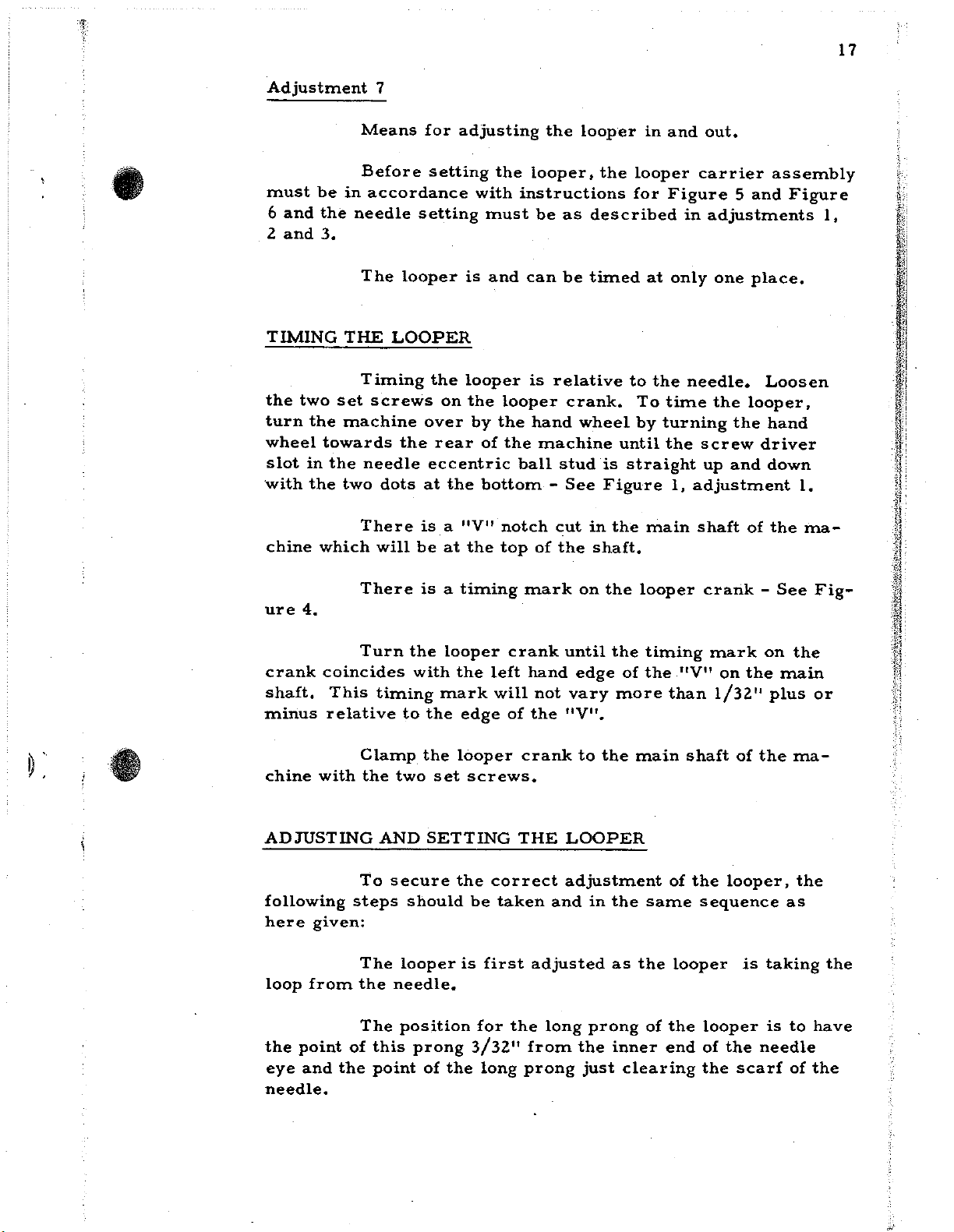
Page 17
16
to
3/32"
the
needle
LOOPER
importance.
-
allow
carrier
must
remove
l/64"
-
be
or
from
carrier
The
The
See
understood
The
the
correct
(See
looper
space
Figure
replace
looper
needle
clamp
setting
adjusting
is
mounted
between
2 -
in
case
this
assembly.
carrier
setting
screw.
chart).
and
for
surface
of
the
in
looper
the
correct
any
assembly
looper
Plate
the
looper
shoulder
assembling
reason
consists
of
is
l.
it
presser
of
the
carrier
and
end
is
necessary
of:
foot.
greatest
assembly
of
looper
of
this
Tighten
unit
to
•
•
sembling
positively
screw.
that
the
distance
est
the
looper
looper
and
which,
Adjustment
side
6.
or
yoke,
for
when
Looper
Clamp
Looper
Looper
The
these
located
The
The
reference
4
Means
looper
parts
looper
ball,
will
looper
the
Yoke -in
Screw
Ball
Carrier
carrier
into
on
the
carrier
from
be
looper
to
for
the
the
4-1/32".
has
to
the
adjusting
the
shaft
edge
side
means
is
taking
which
and
machine.
of
the
is
assembled
of
of
the
See
for
drawing,
the
the
are
the
looper
Now,
looper
the
looper
looper
adjusting
the
are
looper
loop
looper
yoke
carrier
to
the
ball
following
numbered
position
from
yoke
are
the
looper
looper
yoke
pin
nearest
chart -Figures
the
pin
holes
set
before
ball
by a spot
yoke
hole
near-
to
adjustments,
as
follows:
on
the
right
needle.
as-
is
so
the
5
•
hand
Adjustment
side
or
Adjustment
to
right
Means
when
Means
or
5
the
6
right
for
needle
for
to
left.
adjusting
is
between
adjusting
the
the
looper
the
prongs
position
position
of
of
the
on
the
looper
the
left
looper.
from
hand
left
Page 18
17
•
Adjustment
must
6
2
TIMING
the
turn
wheel
slot
with
chine
and
and
two
be
the
3.
set
the
towards
in
the
the
which
7
Means
Before
in
accordance
needle
The
THE
machine
two
LOOPER
Timing
screws
needle
dots
There
will
for
setting
setting
looper
the
over
the
rear
eccentric
at
is a "V"
be
adjusting
the
with
must
is
and
looper
on
the
by
the
of
the
bottom -See
at
the
top
the
looper,
instructions
be
as
can
be
is
relative
looper
hand
the
machine
ball
stud
notch
of
cut
the
looper
the
described
timed
crank.
wheel
is
Figure
in
shaft.
in
looper
for
at
to
To
by
until
straight
the
main
and
Figure
in
only
the
needle.
time
turning
the
1,
out.
carrier
5
and
adjustments
one
place.
Loosen
the
looper,
the
screw
up
adjustment
shaft
driver
and
of
assembly
Figure
1,
hand
down
1.
the
ma-
•
ure
4.
crank
shaft.
minus
chine
ADJUSTING
following
here
loop
the
eye
needle.
coincides
This
relative
with
given:
from
point
and
steps
of
the
There
Turn
timing
Clamp
the
two
AND
To
secure
The
looper
the
needle.
The
position
this
point
is a timing
the
looper
with
the
mark
to
the
edge
the
looper
set
SETTING
the
should
is
prong
of
the
crank
left
will
of
screws.
correct
be
taken
first
for
the
3/32"
long
mark
hand
not
the
crank
THE
and
adjusted
long
from
prong
on
the
until
the
edge
of
vary
more
"V".
to
the
main
LOOPER
adjustment
in
the
as
prong
the
inner
just
clearing
looper
timing
the
than
of
same
the
looper
of
the
end
crank -See
mark
"V"
on
the
1/32"
shaft
of
the
looper,
sequence
is
looper
of
the
the
scarf
on
the
main
plus
the
ma-
the
as
taking
is
to
needle
of
Fig-
or
the
have
the
Page 19
18
ments
are
To
taken
secure
and
this
made:
setting,
the
following
steps
and
adjust-
top
of
the
slowly
of
4,
the
permits
right -and
ment
ner
just
clamp
clamp
tion,
passing
ing
chaining
the
these
until
the
needle.
Figures
looper
the
6,
until
end
of
clears
screw
screw -See
until
chaining
1/32" -See
finger,
previous
should
Turn
hand
wheel
the
Loosen
2
and
just
clears
Loosen
looper
slide
the
the
needle
Check
the
scarf
-
See
Continue
the
short
adjustments
be
the
hand
will
long
prong
the
5 -
and
the
eccentric
the
looper
long
eye.
to
see
of
Figure
Figure
to
prong
finger,
Figure
or
if
the
re-made.
wheel
looper
roll
the
sleeve
prong
that
the
rotate
if
7.
clearance
have
be
moved
of
the
yoke
the
scarf
clamp
sleeve
eccentric
of
point
needle.
5,
and
2.
the
of
the
foot
If
the
in
clockwise
away
looper
clamp
looper
of
the
screw -See
the
looper
of
Tighten
the
hand
looper
has
chaining
short
is
not
been
from
is
screw -See
until
needle.
to
be
moved
sleeve
is
the
long
looper
wheel
is
prong
greater
correctly
direction;
the
over
the
-
Figure
3/32"
prong
the
eccentric
in
clockwise
at
nearest
finger,
does
than
operator
the
center
long
Figure
from
from
of
looper
not
not
1/32",
made,
that
is,
very
line
Adjustment
prong
2 -
this
left
to
2,
adjust-
the
in-
the
looper
yoke
sleeve
direc-
point
exceed-
clear
and
when
the
then
the
t:
•
of
tion
until
the
looper
not
enter
prong
the
looper
looper
short
crotch
the
prongs
until
instead
ing
corrective
the
the
will
eccentric
prong
of
the
the
point
of
Continue
short
slot
in
looper
clear
eccentric
clears
Care
looper
of
the
Continue
of
so
doing
steps
to
rotate
prong
the
the
sleeve
the
must
looper.
to
the
strikes
of
the
foot.
slot
edge
sleeve -Adjustment
be
when
needle
are
in
of
the
edge
taken
the
turn
required:
If
the
the
least
the
should
the
the
the
foot,
of
the
now
needle
hand
crotch
hand
looper
short
looper
amount
looper
as
wheel
enter·
wheel
has
prong
adjust
slot
the
should
of
in
passed
of
so
in
6,
Figure
possible
slot.
needle
be
in
clockwise
between
the
looper
clockwise
the
the
looper
that
the
the
foot
2.
so
may
entering
the
-
direc-
edge
short
by
moving
Move
that
strike
between
direction
prongs
the
of
does
the
the
the
but
follow-
f;
•
Page 20
19
•
Figure
the
needle
er,
clearing
the
two
-
Figure
5,
Figure
distance
tighten
tion
until
center
prong
needle
of
must
tenth
SETTING
ment
of
the
needle.
be
paragraphs
4,
Loosen
4,
and
turn
does
The
needle
the
In
case
prongs -to
2,
and
turn
2,
until
from
the
line
the
and
corrected
Figure
the
sleeve
Continue
the
point
of
the
looper
that
THE
the
In
LOOPER".
5.
the
crank
not
strike
two
prongs
the
correct
the
the
needle.
clamp
to
of
needle.
is
point
case
-
this
inclusive
Do
two
set
slightly
the
must
needle
prongs
rotate
the
3/32"
not
enter
about
this,
looper
When
screw -See
long
Check
of
the
the
above
is
done
under
Be
turn
screws
in a clockwise
crotch.
between
an
should
loosen
eccentric
of
the
this
the
hand
prong
to
from
the
long
conditions
as
the
sure
the
looper
on
the
Tighten
equal
not
enter
the
looper
setting
Figure
wheel
of
the
see
that
inner
prong
described
heading
to
roll
looper
the
prongs
amount.
about
sleeve
sleeve -Adjustment
are
has
2,
in a clockwise
looper
the
end
just
do
"ADJUSTING
the
eccentric
crank -See
direction
the
set
midway
clamp
about
clears
not
in
looper -Adjust-
been
is
point
of
eye
exist,
the
an
over
fifth
sleeve.
screws
of
the
equal
made,
of
the
of
the
they
until
screw
the
the
scarf
to
•
loop-
of
direc-
long
AND
•
cerned,
threads
However,
ding
silks
of
the
ser
er
position
Figure
direction
to
the
RETAINER
presser
needles
firmly
ing
no
is
may
or
hemming
and
needle
foot -Figure
1 -
needle
as
hold
the
material.
loop
will
The
machine,
now
ready
cause a slight
these
cotton,
1/16"
by
re-adjusting
the
timing
towards
resulting
OR
CLOTH
The
Cloth
foot
must
possible
the
work
form,
to
sew.
adjustments
the
more
however,
from
3,
instead
dots
the
hand
in a larger
CLAMP
Retainer
at
all
and
set
on
to
If
the
work
resulting
as
far
variation
heavy
it
the
the
on
wheel
times
the
as
Different
will
give
may
needle
of
3/32",
needle
the
located
be
relative
disc
is
carried
in
missed
the
looper
material
from
the
materials.
be
advisable
setting
without
ball
ball
stud
to
obtain
thread
in
adjusted
to
the
while
stitches.
and
needle
or
different
the
above
best
results
When
to
surface
changing
stud -Adjustment
should
slightly
loop.
the
cloth
a·s
close
ridge
the
needle
along
with
adjustments.
hemming
set
the
on
be
turned
more
opening
to
forming
is
the
are
when
point
the
pres-
the
loop
throw
of
the
disc
penetrat-
needle,
con-
pad-
-
1,
in
the
to
Page 21
20
Part
4-Cll4
4-121
4-126
4-127
6-56
6-70
8-89
8-122
8-123
8-124
8-125
8-128
8-129
14-14
14-260
14-394
14-395
14-400
14-429
14-432
14-434
14-435
14-440
14-441
PARTS
No.
Plate
20
15,
8
22,
23, 24,
25
17
4
16,
15,
16,
24
15,24
16
15,
3
8
5,
19,
21
4,
6,
6,
4,5,6,9
2, 4
10,
10,
20,
21
LIST
16
24
24
16
20,
7
9
11
11
21
FOR
LEWIS
Work
and
Aluminum
bracket
150-20
Work
when
Models
Work
when
Needle
Needle
Belt
Guard
150-16,
Guard
150-16,
Guard
5/16"
Guard
5/16
Guard
150-20,
Guard
150-20,
Shaft
Shaft
Work
Shaft
Cylinder
150-15,-17,-23
Shaft
Shaft
Shaft
for
150-23
Main
Shaft
Models
Shaft
Cylinder
Shaftfor
Model
Jack
Plate
150-23
50-234
Plate
end
150-1,
Plate
using
Guide
Guide,
Guard
for
ri~ht
3/8
for
left
3/8";
fo~·
belt
for
11
belt
for
ri~ht
3/8
for
left
3/8"
for
in
Bracket
Plate
for
Base
in
Base
for
Knee
in
Base
150-1,-5,-7,-9,-15,-16,-17,-20,
Shaft
in
Base
150-6,
for
Base -Model
Crank
150-23
Shaft
CLASS
Description
(large)
Work
(swing
cover
(swing
32-264
';
Model
hand
right
loops,
left
loops,
I
hand
Needle
4-126,
Ridge
for
to
for
Ridge
in
150
for
Plate
for
type)
32-264
150-15
type)
Model
Model
hand
top
Model
hand
Model
hand
Model
hand
top
Carrier
50-211
Forming
150-1,
Gear
Press
depress
Feed
150-6TS
Forming
48-138
Arm -Model
MACHINES
Models
attached
Model
in
in
150-20
top
knife,
150-20,
knife,
150-20,
top
150-16
top
150,-16
top
knife,
knife,
for
4-127
-5,
-6, -7,
27-165
Feed
Plate
150-6TS
to
150-7
150-16,
404-126
is
used.
404-127
150-9
Model
5/16
Model
5/16"
knife
knife
4118-24
swinging
Holders
shog
for
Model
Model
Disc
Plates
Disc
disc
150-23
to
in
in
-9,
in
•
11
•
• •
Page 22
21
•
•
Part
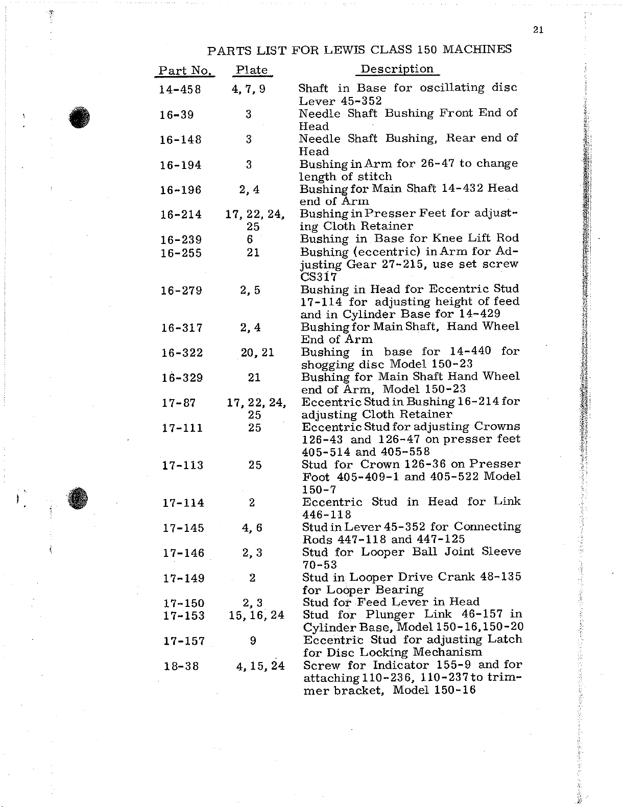
14-458
16-39
16-148
16-194
No.
16-196
16-214
16-239
16-255
16-279
16-317
16-322
16-329
17-87
17-111
17-113
17-114
17-145
17-146
17-149
17-150
17-153
17-157
18-38
PARTS
Plate
4,
2, 4
17,
2, 5
2, 4
20, 21
17,
4,
2,
15,16,24
4,
LIST
7,
9
3
3
3
22, 24,
25
6
21
21
22,
24,
25
25
25
2
6
3
2
2, 3
9
15,
24
FOR
LEWIS
Description
Shaft
Lever
Needle
Head
Needle
Head
BushinginArm
length
BushingforMain
end
Bushing
ing
Bushing
Bushing
justing
CS317
Bushing
17-114
and
Bushing
End
Bushing
shogging
Bushing
end
Eccentric
adjusting
Eccentric
126-43
405-514
Stud
Foot
150-7
Eccentric
446-118
Stud
Rods
Stud
70-53
Stud
for
Stud
Stud
Cylinder
Eccentric
for
Screw
attachingll0-236,
mer
in
Base
45-352
Shaft
Shaft
of
stitch
of
Arm
in
Cloth
in
(eccentric)
Gear
in
for
in
Cylinder
for
of
Arm
disc
for
of
Arm,
and
and
for
Crown
405-409-1
in
Lever
447-118
for
in
Looper
Looper
for
Feed
for
Base,
Disc
Locking
for
bracket,
Presser
Retainer
in
Stud
Cloth
Stud
Looper
CLASS
for
Bushing
Bushing,
for
Base
27-215,
Head
adjusting
Base
Main
base
Model
Main
Model
in
Retainer
for
126-47
405-558
Stud
45-352
and
Drive
Bearing
Lever
Plunger
Model
Stud
for
Indicator
Model
150
MACHINES
oscillating
Front
Rear
26-47
Shaft
for
for
Shaft,
Bushing
126-36
and
in
14-432
Feet
Shaft
adjusting
447-125
Ball
Mechanism
for
Knee
in
Arm
use
Eccentric
height
for
Hand
for
14-440
150-23
Hand
150-23
on
presser
405-522
Head
for
Joint
Crank
in
Head
Link
150-16,150-20
adjusting
155-9
110-237to
150-16
disc
End
of
end
of
to
change
Head
adjust-
Lift
Rod
for
Ad-
set
screw
Stud
of
feed
14-429
Wheel
for
Wheel
16-214
on
Presser
for
Connecting
46-157
for
Crowns
feet
Model
Link
Sleeve
48-1~5
Latch
and
for
trim-
in
Page 23

22
Part
18-70
18-71
18-74
18-CllO
18-121
18-125
18-C186
18-261
18-270
18-277
18-281
18-292
18-295
18-307
18-318
18-326
18-330
18-345
18-355
18-391
No,
18-375
18-400
18-416
18-492
18-493
18-500
PARTS
1 7,
22,
12,18,19,
2,
17,
LIST
Plate
3
2
3
13,
8
11
13,
13
22,
8
23
23,
10,
3,
21,
6
13,
25
4
16
3,
16
22,
25
2
6
9
14
14
24
25
11
17
25
14
15
24,
FOR
LEWIS
Clamp
Clamp
Spot
Screw
carrier
Screw
50-223
405-538,
Screw
s·crew
Set
Screw
ing
folders,
Screw
Screw
Screw
Screws
110-230
and
150-6TS
Screw
presser
Bearing
base,
Screw
ket
150-16,
Screw
44base,
Screw
knee
Screw
for
150-15
Screw
405-514,
Screw
regulator
Screws
3/8
Screw
4124-56
Screws
3/8
Screw
eccentric
Spot
Screw
Set
stud
Models
50-160,
275
Models
lift
bracket
inch;
inch
Screw
Screw
17-157
CLASS
Description
Screw
Screw
for
to
in
for
for
in
in
for
for
for
for
for
for
for
for
for
in
for
for
in 4 79-8 to
4118-15
attaching
presser
Models
shaft14-260for
Spring21-332
for
Models
attaching
end
work
attaching
to
presser
holding
feet
Screw
holding
-20
attaching
to
plunger
clamping
shaft
cover 3 2-107
50-223,
presser
405-522,
107-51
in
cylinder
for
top
Model
447-97-1
and
447-23,
for
top
bushing
stud 1 7-
for
70-28
in
base
150
needle
for
looper
feet
150-9
collar
of
eccentric
plate
for
feed
150-6
presser
and
150-7
in
base
405-558
ridge
knives,
150-20,
knives,
87
eccentric
sleeve
for
MACHINES
carrier
locate
folder
405-497, 405-537,
and
Model
39-C255
150-9,
1733 L to
for
holding
roll
forming
feet,
chaining
and
for
26-152
and
in
16-214
plate
150-6TS
22-257,
ridge
150-23
39-117
of
arm
on
Models
foot
base
Model
5/16
head,
Model
Model
in
presser
433-93
for
locking
Models
forming
4118-
yoke
foot
forming
head,
449-27
on
looper
bracket
150-15
work
150-6TS
for
locat-
150-15
50-280
stud
folders
fingers
in
cylinder
to
in
cylinder
collar
150-9
405-409-1,
150-16,
inch
screws
150~16
150-20,
for
holding
foot
in
knee
eccentric
17-
150-6
brac-
Model
screw
24
plate
87
plate
disc
and
disc
head
press
L
to
to
in
•
•
Page 24
23
~
:
•
•
Part
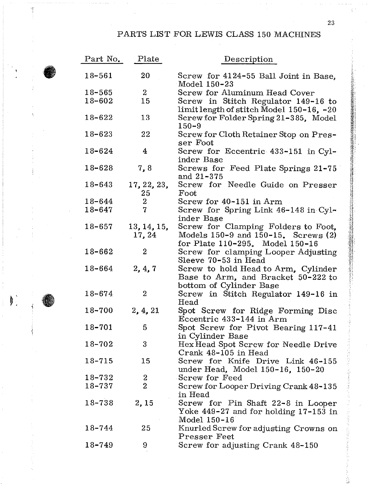
18-561
18-565
18-602
18-622
18-623
18-624
18-628
18-643
18-644
18-647
18-657
18-662
18-664
18-674
18-700
18-701
18-702
18-715
18-732
18-737
18-738
18-744
18-749
PARTS
No
.
LIST
Plate
20
2
15
13
22
4
7,
8
17,
22,
23,
25
2
7
13, 14, 15,
17,
24
2
2,
4,
7
2
2,
4,
21
5
3
15
2
2
2,
15
25
9
FOR
LEWIS
Screw
Model
Screw
Screw
limitlengthofstitchModel
Screw
150-9
Screw
ser
Screw
inder
Screws
and
Screw
Foot
Screw
Screw
inder
Screw
Models
for
Screw
Sleeve
Screw
Base
bottom
Screw
Head
Spot
Eccentric
Spot
in
HexHead
Crank
Screw
under
Screw
Screw
in
Screw
Yoke
Model
Knurled
Presser
Screw
for
150-23
for
for
for
Foot
for
Base
21-375
for
for
Base
for
Plate
for
to
to
Screw
Screw
Cylinder
48-105
Head,
for
for
Head
449-27
150-16
for
CLASS
Description
4124-55
Aluminum
in
Stitch
Folder
Cloth
Eccentric
for
Feed
for
70-53
of
in
for
for
Needle
40-151
Spring
Clamping
150-9
110-295.
clamping
hold
Arm,
Cylinder
Stitch
433-144
for
Base
Spot
Knife
Feed
Looper
Pin
Screw
Feet
adjusting
Regulator
Spring
Retainer
and
in
Head
Head
and
Regulator
for
Ridge
Pivot
Screw
in
Head
Model
Driving
Shaft
and
for
for
Plate
in
Link
150-15.
adjusting
150
MACHINES
Ball
Guide
Bracket
Base
in
Drive
150-16,
Joint
Head
21-3
Stop
433-151
Springs
Arm
46-148
Folders
Model
Looper
to
Arm,
Forming
Arm
Bearing
for
22-8
holding
Crank
in
Base,
Cover
149-16
150-16,
85,
on
on
Presser
to
Screws
150-16
Adjusting
Cylinder
50-222
149-16
Needle
Link
150-20
Crank48-135
in
17-153
Crowns
48-150
-20
Model
Pres-
in
Cyl-
21-7
in
Cyl-
Foot,
Disc
117-41
Drive
46-155
Looper
to
5
(2)
to
in
in
on
Page 25
24
Part
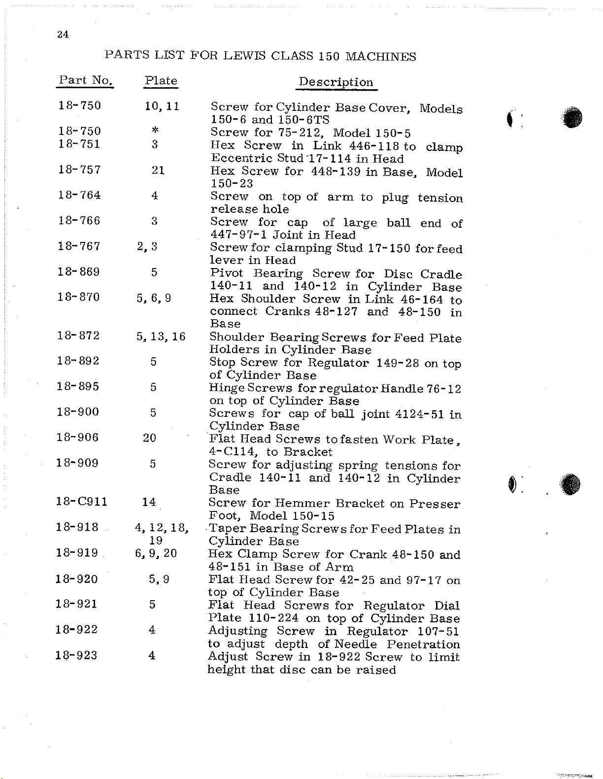
18-
No.
750
18-750
18-
751
18-757
18-
764
18-766
18-767
18-869
18-
870
18-872
18-
892
18-895
18-900
18-906
18-909
18-C911
18-918
18-919
18-920
18-921
18-922
18-923
PARTS
2, 3
5, 6, 9
5,
4,
6,
LIST
Plate
10,
*
3
21
4
3
5
13,
5
5
5
20
5
14
12,
19
9,
5,9
5
4
4
11
18,
20
16
FOR
Screw
150-6
Screw
Hex
Eccentric
Hex
150-23
Screw
release
Screw
447-97-1
Screw
lever
Pivot
140-11
Hex
connect
Base
Shoulder
Holders
Stop
of
Hinge
on
Screws
Cylinder
Flat
4-Cll4,
Screw
Cradle
Base
Screw
Foot,
.
Taper
Cylinder
Hex
48-151
Flat
top
Flat
Plate
Adjusting
to
Adjust
height
LEWIS
for
and
for
Screw
Screw
on
hole
for
for
in
Bearing
and
Shoulder
Screw
Cylinder
Screws
top
of
for
Head
for
140-11
for
Model
Bearing
Clamp
in
Head
of
Cylinder
Head
110-224
adjust
Screw
that
CLASS
Description
Cylinder
150-6TS
75-212,
in
Stud
for
top
cap
Joint
clamping
Head
140-12
Cranks
Bearing
in
Cylinder
for
Base
for
Cylinder
cap
Base
Screws
to
Bracket
adjusting
Hemmer
150-15
Base
Screw
Base
Screw
Screws
Screw
depth
in
disc
150
Base
Model
Link
'17-114
448-139
of
arm
of
large
in
Head
Stud 1 7-150
Screw
Screw
48-127
Screws
Base
Regulator
regulator
Base
of
ball
to
fasten
spring
and
140-12
Bracket
Screws
for
of
Arm
for
42-
Base
for
on
top
in
of
Needle
18-922
can
be
MACHINES
Cover,
150-5
446-118
in
Head
in
to
to
Base,
plug
ball
for
Disc
in
Cylinder
in
Link
and
for
46-164
48-150
Feed
149-28
Handle
joint
4124-51
Work
tensions
in
Cylinder
on
Presser
for
Feed
Crank
25
48-150
and
Plates
97-1 7 on
Regulator
of
Cylinder
Regulator
Penetration
Screw
raised
Models
clamp
Model
tension
end
for
feed
Cradle
Base
Plate
on
76-12
Plate,
Dial
Base
107-51
to
limit
of
to
in
top
in
for
in
and
< •
,
.•....
Page 26
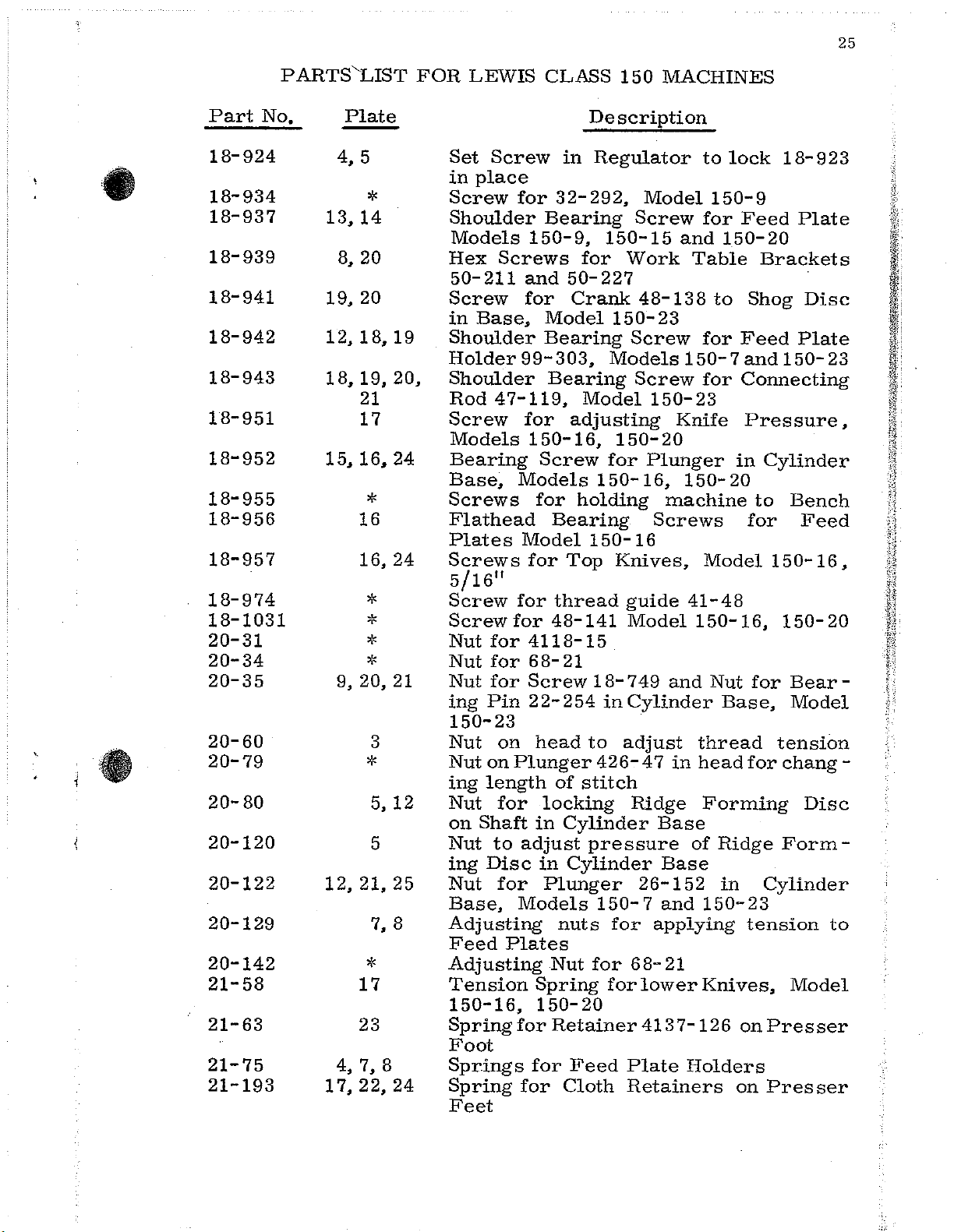
25
•
i.
Part
18-924
18-934
18-937
18-939
18-941
18-942
18-943
18-951
18-952
18-955
18-956
18-957
18-974
18-1031
20-31
20-34
20-35
20-60
20-79
20-80
20-120
20-122
20-129
20-142
21-58
21-63
21-75
21-193
No.
PARTS'LIST
Plate
4, 5
*
13,
14
8,
20
19,
20
12,18,19
18,
19,
21
17
15, 16,
*
16
16,
*
*
*
*
9, 20,
3
*
5,
5
12,21,25
7, 8
*
17
23
4, 7, 8
17,22,24
20,
24
24
21
12
FOR
Set
in
Screw
Shoulder
Models
Hex
50-211
Screw
in
Shoulder
Holder
Shoulder
Rod
Screw
Models
Bearing
Base,
Screws
Flathead
Plates
Screws
5/16
Screw
Screw
Nut
Nut
Nut
ing
150-23
Nut
Nut
ing
Nut
on
Nut
ing
Nut
Base,
Adjusting
Feed
Adjusting
Tension
150-16,
Spring
Foot
Springs
Spring
Feet
LEWIS
Screw
place
for
Screws
and
for
Base,
99-303,
47-119,
for
Models
Model
11
for
for
for
for
for
Pin
on
on
Plunger
length
for
Shaft
to
adjust
Disc
for
Models
Plates
for
for
CLASS
Description
in
32-292,
Bearing
150-9,
for
50-227
Crank
Model
Bearing
Bearing
Model
adjusting
150-16,
Screw
for
holding
Bearing
150-16
for
Top
thread
48-141
4118-15
68-21
Screw
22-254
head
in
in
Spring
150-
for
to
of
stitch
locking
Cylinder
pressure
Cylinder
Plunger
nuts
Nut
for
20
Retainer
Feed
Cloth
150
MACHINES
Regulator
Model
Screw
150-15
Work
48-138
150'-23
Screw
Models
Screw
150-23
150-20
for
Plunger
150-
18-749
426-47
150-7
16,
machine
Screws
Knives,
guide
Model
and
inCylinder
adjust
Ridge
Base
Base
26-152
and
for
applying
68-21
for
lower
4137-126
Plate
Retainers
to
150-9
for
and
Table
to
for
150-7
for
Knife
150-
Model
41-48
150-16,
Nut
thread
in
head
Forming
of
150-23
Knives,
Holders
lock
150-20
in
20
Base,
Ridge
in
18-923
Feed
Brackets
Shog
Feed
and
150-23
Connecting
Pressure,
Cylinder
to
for
150-16,
150-20
for
tension
for
chang-
Form
Cylinder
tension
on
Presser
on
Presser
Plate
Disc
Plate
Bench
Feed
Bear-
Model
Disc
-
to
Model
Page 27
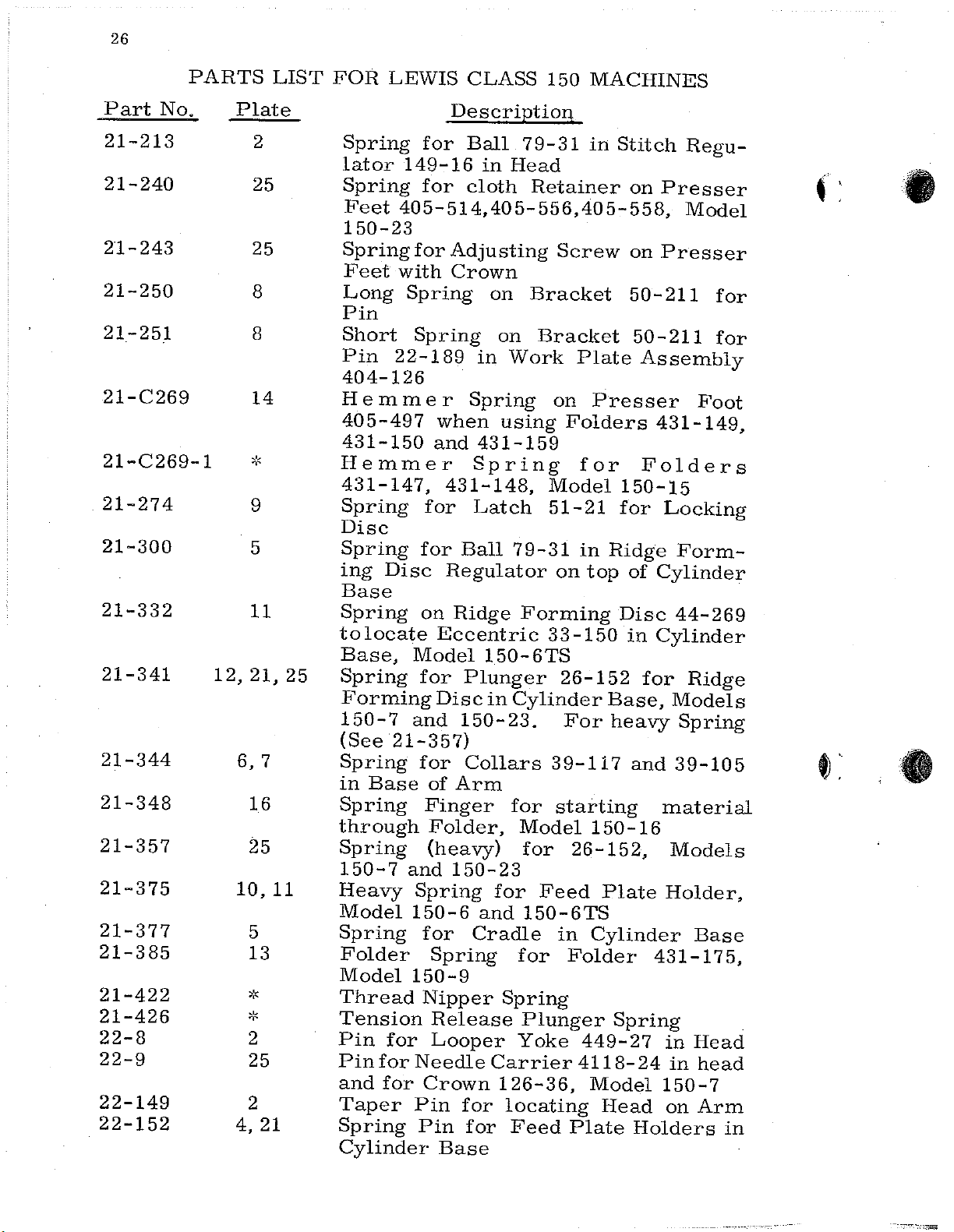
26
Part
21-213
21-240
21-243
21-250
21-251
21-C269
21-C269-1
21-274
21-300
21-332
21-341
21-344
21-348
21-357
21-375
21-377
21-385
21-422
21-426
22-8
22-9
22-149
22-152
No.
PARTS
Plate
12,
6, 7
10,
4,
2
25
25
8
8
14
9
5
11
21,
16
25
5
13
*
2
25
2
21
LIST
25
11
FOR
Hemmer
Spring
Spring
ing
Spring
tolocate
Base,
Spring
Forming
150-7
{See
Spring
in
Spring
through
Spring
150-7
Heavy
Model
Spring
Folder
Model
Thread
Tension
Pin
Pin
and
Taper
Spring
Cylinder
LEWIS
Spring
lator
Spring
Feet
150-23
Spring
Feet
Long
Pin
Short
Pin
404-126
Hemmer
405-497
431-150
431-147,
Disc
Base
22-189
Disc
21-357)
Base
for
for
for
CLASS
Description
for
Ball
149-16
for
405-514,405-556,405-558,
for
with
Spring
Spring
and
for
for
on
Model
for
and
for
of
Finger
Folder,
{heavy)
and
Spring
150-6
for
Spring
150-9
Nipper
Release
Looper
Needle
Crown
Pin
Pin
in
cloth
Adjusting
Crown
on
on
in
Spring
when
431-159
Spring
431-148,
Latch
Ball
Regulator
Ridge
Eccentric
150-6TS
Plunger
Disc
Base
in
150-23.
Collars
Arm
150-23
for
and
Cradle
Carrier
126-36,
for
for
150
79-31
Head
Retainer
Screw
Bracket
Bracket
Work
on
using
Model
51-21
79-31
on
Forming
33-150
Cylinder
39-117
for
starting
Model
for
Feed
150-6TS
in
for
Spring
Plunger
Yoke
locating
Feed
MACHINES
in
Stitch
Plate
Presser
Folders
for
150-15
for
in
Ridge
top
Disc
26-152
Base,
For
heavy
150-16
26-152,
Plate
Cylinder
Folder
Spring
449-27
4118-24
Model
Head
Plate
Regu-
on
Presser
Model
on
Presser
50-211
50-211
Assembly
431-149,
Folders
Locking
Form-
of
Cylinder
44-269
in
Cylinder
for
Ridge
Models
Spring
and
39-105
material
Models
Holder,
Base
431-175,
in
Head
in
150-7
on
Holders
for
for
Foot
head
Arm
in
.F
..
.•
•
-
---_-,,,?,laj;
Page 28
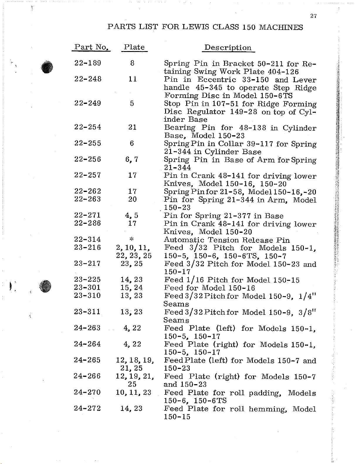
27
•
Part
22-189
22-248
22-249
22-254
22-255
22-256
22-257
22-262
22-263
22-271
22-286
22-314
23-216
23-217
23-225
23-301
23-310
23-311
24-263
24-264
24-265
24-266
24-270
24-272
No.
PARTS
Plate
8
11
5
21
6
6,
17
17
20
4,
17
*
2,
10,
22, 23,
23,
14,
15,
13,
13,
4,
4,
12,18,19,
21,
12, 19,
25
10,11,23
14,
LIST
7
5
11,
25
23
24
23
23
22
22
25
23
25
21,
FOR
Spring
taining
Pin
handle
Forming
Stop
Disc
inder
Bearing
Base,
SpringPin
21-344
Spring
21-344
Pin
Knives,
Spring
Pin
150-23
Pin
Pin
Knives,
Automatic
Feed
150-5, 150-6,
Feed
150-17
Feed
Feed
Feed
Seams
Feed3/32Pitchfor
Seams
Feed
150-5,
Feed
150-5,
FeedPlate
150-23
Feed
and
Feed
150-6,
Feed
150-15
LEWIS
Pin
Swing
in
Pin
Regulator
Base
Model
in
Pin
in
Crank
Pin
for
for
in
Crank
3/32
3/32
1/16
for
3/32Pitchfor
Plate
150-17
Plate
150-17
Plate
150-23
Plate
150-6TS
Plate
CLASS
Description
in
Eccentric
45-345
Disc
in
107-51
Pin
in
Cylinder
in
Model
for
Spring
Spring
Model
Tension
Pitch
Pitch
Pitch
Model
(right)
(left)
(right)
for
for
Bracket
Work
to
in
Model
149-28
for
150-23
Collar
Base
48-141
150-16,
21-58,
21-344
21-377
48-141
150-20
150-6TS,
for
for
150-16
(left)
for
roll
roll
150
MACIIlNES
50-211
Plate
33-150
operate
150-6TS
for
Ridge
48-138
39-117
Base
of
Arm
for
150-20
Model
in
in
for
Release
for
Models
Model
Model
Model
Model
for
Models
for
Models
Models
for
Models
padding,
hemming,
404-126
and
Step
Forming
on
top
in
Cylinder
for
for
driving
150-16,-20
Arm,
Base
driving
Pin
150-7
150-23
150-15
150-9,
150-9,
150-7
for
Re-
Lever
Ridge
of
Cyl-
Spring
Spring
lower
Model
lower
150-1,
and
1/4"
3/8"
150-1,
150-1,
and
150-7
Models
Model
Page 29
28
Part
24-277
24-278
24-294
24-295
24-300
26-47
26-152
26-160
27-76
27-165
27-166
27-215
30-52
30-68
30-C258
32-106
32-107
32-208
32-210
32-225
32-229
32-262
32-264
32-292
No.
PAR'I'S
Plate
16,
16,24
13,
13,
12,
15, 16, 17,
20,
18,20,21
15,
24
23
23
3
18,
25
24
21
4
4
3
13
14
2
2
11
10
12
2
8
4
LIST
21,
16
FOR
LEWIS
Feed
150-16
Feed
150-16
Feed
Feed
Feed
Plunger
stitch.
Plunger
44-275,
Plunger
Model
Gear
27-215,
Gear
Forming
Gear
Forming
Gear
Needle
Spring
Clamp
Foot,
Cover,
Cover
Cover
End
150-6TS
End
150-6
Cover
150-7
Cover
Model
Cover,
Cover
150-1,
Cover
Description
Plate,
Plate,
Plate,
Plate,
Plate,
in
Arm
(See
for
Models
for
150-16,
on
Main
Model
(large)
Disc
(small)
Disc
for
Shagging
Clamp
Clamp
for
Hemmer
Model
Aluminum,
Plate
32-106
Cover
Cover
for
end
and
150-23
for
150-16,
Aluminum,
for
End
150-5,
for
Top
CLASS
Right
Left
Model
Model
Model
for
426-47)
holding
150-7
Node
150-20
Shaft
150-23
for
in
for
in
for
150-15
(rear)
for
Cylinder
for
Cylinder
of
Cylinder
Bottom
150-20
of
Cylinder
150-9,
of
150
Hand
Hand
150-9,
150-9,
150-20
adjusting
Ridge
in
for
rolling
Base
rolling
Base
Disc,
Folder
Spring
for
for
of
for
Arm
MACHINES
Side,
Side,
1/4"
3/8"
length
Forming
and
150-23
Cylinder
driving
back
of
Arm
back
of
Arm
Model
Model
on
Presser
Head
Aluminum
Base,
Base,
Base,
Bracket
Head
Base,
150-15,
Models
50-234,
Models
150-17
Model
Model
Seams
Seams
of
Disc
Base,
gear
Ridge
Ridge
150-23
150-9
Head
Model
Model
4:
•
Page 30
29
•
•
Part
33-149
33-150
34-31
34-48
35-21
36-16
39-87
39-92
39-95
39-99
39-105
39-117
39-118
40-26
40-38
40-57
40-60
40-63
40-126
40-144
40-148
40-151
40-154
PARTS
No.
LIST
Plate
2
11
20,
21
4
3
2, 4, 8
16,
24
6
4, 7
6
5,
16
20
*
19
3
17
2
5
5
2
14
FOR
of
Washers
Washer
75-212onCylinder
Slap
Joint
Lock
Washer
Forming
SpacingWasherfor
448-131
Washer
Shaft
Washer
Holder
150-15
LEWIS
Eccentric
length
Eccentric
Ridge
stitching,
Automatic
Cam
Cam
Model
Roll
back
Arm
Looper
Stop
Collar
Table
Collar
Cylinder,Base,
Spacing
of
Arm
Collar
Thrust
Arm
Collar
14-394,
Bracket
Fiber
Fiber
of
FormingDisc44-270
for
150-23
for
Ridge
Collar
404-126
for
on
Washer
slap
slap
under
Washers
in
99-298
CLASS
Description
for
stitch
t o
Model
Tension
Shogging
turning
in
Head
on
Main
Plunger
Collar
Shaft
Collar
on
Ridge
414-449
for
50-227
for
washer
head,
for
Disc
in
Cylinder
on
Eccentric
Arm
between
Forming
Screw
pants
for
washer
Nut
150
Feed
in
Head
adjust
150-6TS
Release
Ridge
Gear
Shaft,
and
Plunger
Link
Model
on
Shaft
14-395
on
Shaft
Forming
in
Cylinder
18-939
to
machine
bottom
Base,
4124-55,
on
Model
on
feed
20-80
Shaft
Ball
Feed
in
Cylinder
MACHINES
Lever
supplementary
for
Pin
Forming
27-165,
Disc
150-16,
14-440
in
14-400
Ball
for
150-16,
screws
in
in
Base
433-144
Plate
in
in
Swing
Gear
Stud 1 7-153
Base
Disc
for
Edge
Model
Model
79-2 8 in
4124-56
end
Cylinder
79-9
24-272
Base
to
adjust
through
Raising
Disc,
to
roll
base
Work
in
150-20
in
Base
of
Arm
in
Base
Shafts
Base
attaching
Guide
150-5
150-23
Head
Ball
150-20
in
Head
of
Ridge
Base
in
Crank
on
Main
and
Model
of
Page 31

30
Part
40-159
41-1
41-42
41-48
41-49
42-13
42-24
42-25
44-253
44-269
44-270
44-272
44-275
44-276
44-277
44-278
44-287
44-291
44-294
44-296
45-345
45-351
45-352
PARTS
No.
Plate
19,
22,
11,
11,
14,
12,
10,
13,
4,
21
3
3
*
*
22
22
9
23
23
23
23
18,
25
23
22
22
*
23
*
22
11
*
5,
LIST
21,
6
FOR
LEWIS
Washer
Cylinder
Thread
Th
r e
ad
468-23-1
Thread
Thread
Stop
Foot
Stop
Feet
405-394-8,405-395-l,405-419,405-502
and
Stop
Ridge
150-17
Ridge
Model
Supplementary
through
Ridge
Model
Ridge
padding,
and
Ridge
Model
Ridge
405-508
150-1
Ridge
405-419
Ridge
Heavy
Ridge
Model
Disc
Light
Ridge
150-5,
Handle
Ridge
Model
Link
Lever
Disc
for
405-508
for
40
405-529
Pin
Forming
Forming
150-6TS
Forming
150-15
Forming
150-23
Forming
150-6
Material,
Forming
150-9
in
Work
Forming
150-6TS
Motion
in
CLASS
Description
for
Ball
Base,
Guide
Guide
on
Head
Guide,
Guide,
cloth
cloth
5-393-2,405-394-4,405-394-5,
in
Cylinder
stitch,
and
bluff
Forming
on
tropicals
Forming
on
knit
Forming
444-294
Forming
use
with
Lever
for
base
to
Feed
oscillating
of
150
in
Crank
Model
on
needle
under
screw
screw
retainers
retainers
Disc,
Disc
Ridge
for
Model
Disc,
Disc,
edge
Disc
material,
Disc
Arm
for
Disc
and
Disc
Disc
Model
Disc
Model
Disc
retainer
adjust
for
Lever
MACH1NES
448-137
150-23
end
tension
18-974,
LS314
on
on
Base
Models
through
Forming
150-6TS
for
rolled
yielding,
Models
Roll
used
rayons,
used
for
150-1
for
150-23.
(Beaded)
supplementary
through
Ridge
Padding,
with
with
Model
Padding
Book
137-141
in
of
Head
staff
LS314
Presser
Presser
150-1,
stitch,
Disc
Forming
for
hem,
for
fur
150-7
foot
Model
foot
150-1
on
Seams,
Extra
Model
stitch
•
Page 32

31
(:
•:
•
Part
45-357
45-403
45-429
45-457
46-148
46-155
46-157
46-164
47-119
48-105
48-127
48-138
48-141
48-150
48-151
50-88
50-160
50-210
50-211
50-222
50-223
50-227
50-233
50-234
50-280
50-281
PARTS
No.
L 13
LIST
Plate
18,
20,
21
15
20
7
15
15,16,24
5, 6, 9
18, 19,
4,
19,
15,
4,
3,17
4,
13,
15,
15,
20,
21
3
5, 6, 9
20,
17
6,9
20
~'
4,
7
8
6,
7
14
20
16,
17
~·
21
17
FOR
disc
LEWIS
Description
Fork
Feed
150-20
Lever
disc,
Nipper
Link
Drive-Link
Model
Plunger
Link
48-127
Connecting
forming
150-23
Crank
Crank
feed
Crank
for
150-23
Crankfor
150-16,
Crank
plates
in
Crank
plates
Model
Presser
Bracket
on
Bracket
feed
Bracket
Bracket
base
Bracket
Models
Bracket
Bracket
feed
Bracket
beltloopknives,
Bracket
Nipp
FP539
Lever
in
arm,
Lever
for
in
Rod
for
spring
150-16,
Link,
connecting
in
disc
for
on
plates
on
shagging
150-20
on
and
base
head
of
on
and
150-23
Foot
for
plate
for
fastened
on
150-9
for
plate
for
er
base
base
driving
shaft
shaft
driving
shaft
roll
arm
shaft
roll
on
holder
on
holder,
attached
Rod
CLASS
for
shagging
Model
in
oscillating
Lever
for
Rod
in
in
cylinder
ridge
back
back
Bracket
both
end
swing
presser
and
large
end
folder
150
head,
of
arm,
21-344
knives
150-20
Model
crank
of
arm
for
base
needle
14-429
14-440
forming
lower
14-400
14-400
ridge
sides
of
work
to
150-15
work
of
Model
to
Model
adjusting
Guide
MACHINES
ridge
150-23
Model
ridge
Model
in
150-16,
48-150
shagging
of
shaft
for
base
on
knives,
to
depress
ridge
cylinder
bottom
cylinder
forming
to
depress
forming
for
Model
of
table
foot
table
150-16,
cylinder
150-16,
Bracket,
forming
150-16,
forming
150-23
base
under
arm,
base
disc,
presser
for
of
150-20
to
crank
Model
in
depressing
of
Model
Model
150-1
base
404-126
of
cylinder
folders,
404-114
base
150-20
base
150-20
screw
screw
arm
head,
ridge
head
arm
feed
disc
feed
disc,
7
feet
for
for
for
Page 33

32
Part
51-14
51-21
57-17
62-21
62-25
63-29
63-30
63-33
68-21
70-28
70-52
70-53
70-54
70-55
70-72
71-87
71-88
71-105
75-153
75-210
75-212
75-215
PARTS
No.
Plate
8
9
2
21
2,
6
17,24
17,
24
17
S'
-·
6
6
2
6
i9,
21
S'
"'
6
15
*
25
22
22
LIST
FOR
LEWIS
Latch
Latch
Hand
Oil
150-23
Oil
447-125
Felt
Model
5/16"
Felt
for
Felt
Model
Thread
Sleeve
to
Bearing
Rod
Sleeve
Ball
Sleeve
48-150
Sleeve
Base,
Automatic
Rod
Connecting
knives
150-20
Nipper
Edge
405-522, 405-514, 405-558,
150-7,
Edge
and
Edge
Bottoms,
Edge
40
405-395-1,
for
for
Wheel
Cup
Cup
Oil
Oil
5/16"
Oil
150-20,
for
Shaft
447-118
Joint
on
Model
for
Guide
Guide
405-529
G,1ide
Guide
5-3
CLASS
Description
Swing
Locking
for
Shaft
for
Connecting
in
Arm
Pads
150-16,
Pads
Pads
Tension
14-400
Sleeve
in
Shaft
in
Base
for
Knee
under
Rod
150-23
Model
94-4,
between
between
Belt
between
3/8"
connecting
in
in
Arm
Head
4124-27
14-400
of
Crank
150-23
Tension
Press
Rod
for
Presser
for
Presser
on
Cylinder
for
Presser
405-394-5, 405-494-8,
Models
150
Work
Disc
14-441
Rod
3/8";
Loops,
Staff
Knee
Base
Bushing
for
adjusting
Arm
448-137
Staff
4129-18
only
Head.
150-5.
150-1
MACHINES
Table
in
Arm,
Lower
Model
Lower
Model
Lower
of
in
to
locate
Sleeve
for
Model
Feet
Foot
Base
Screw
Feet
404-126
Mechanism
Model
44
7-118
Knives,
150-20,
Knives
150-16
Knives,
Press
Arm
Connecting
in
Cylinder
operating
405-409-1
for
405-393-2
and
Rod
Looper
Lever
150-16,
Models
405-419
Pants
18-750
150-5
•
and
•
••
Page 34

33
PARTS
(.:
•
Part
76-12
79-9
79-28
79-31
79-35
97-17
99-304
107-44
107-51
110-224
110-227
110-230
No.
19,20,21
12, 19,
,.
.
~.
110-234
110-236
110-237
110-238
110-285
110-286
110-293
Plate
5
5,
15
3
2,
5
5,
9
25
5
4,
5
4, 5
11
23
17,24
17,24
17,
24
17,
24
16,24
16,24
24
LIST
21,
FOR
LEWIS
Description
Handle
ing
Base
Ball
4124-56,
4124-56
Ball
oscillating
Ball
149-16
in
Base
Ball
Cylinder
Cover
Holder,
Disc
Flange
on
Flange
tor
More-or-less
Disc
SwingcoverPlate
Cylinder
Roll
405-502
Models
Spacing
150-16,
Cover
Model
5/16
Cover
5/16
Spacing
Belt
Spacing
150-16,
Spacing
wide
Supporting
150-16,
of
Ridge
Stud
Stud
in
stitch
in
Stud
Plate
Plunger
for
shaft
for
149-28
regulator
Forming
Presser
150-6
Plate
Plate
150-16,
11
Plate
11
Belt
Plate
Loops,
plate
Belt
Regulator
Forming
for
Sold
in
Needle
Head,
for
Base,
Yielding,
Driving
14-394
Ridge
on
Base,
3/8";
Loops.
Plate
3/8";
Loops.
3/8";
CLASS
447-23,
in
447-23,
447-97-1
adjusting
and
Ball
Model
on
top
26-152
in
Forming
top
Dial
on
Model
Plate
Feet
and
for
Lower
Model
for
top
3/8";
for
top
for
Lower
Model
for
Model
for
Plate
Model
150
MACHINES
149-28
Disc
Shaft
Ridge
of
top
for
150-6TS
top
for
on
in
penetration
Joint
150-23
of
for
Ridge
in
Cylinder
Cylinder
for
Ridge
of
32-208
150-6TS
for
150-20,
of
Bracket
of
Bracket
Model
150-16
top
Knives,
150-20,
Knives
Model
Oil
150-20,
for
top
Cylinder
4124-51
4124-51,
Ball
in
Cylinder
Cylinder
Cylinder
on
Knives,
Model
Knives,
Joint
Head
Regulator
4124-55
Forming
Forming
Base
Disc
Forming
on
bottom
Roll
Padding,
150-16
for
150-16
Pads,
adjust-
and
and
for
dial
(2)
used
Base
Base
Disc
regula-
Base
Base
end
Model
5/16
11
50-234,
150-20,
50-234,
5/
16"
Model
5/16"
5/16"
Model
5/16"
in
of
of
Page 35

34
Part
No.
110-294
110-295
110-300
110-310
110-311
110-312
110-314
115-118
117-41
119-68
119-69
119-70
122-35
122-37
122-C38
122-39
122-43
125-23
126-36
126-43
PARTS
Plate
17,
15,
15,
16,
15, 16,
22,23,25
24
24
~'
17
17
17
16
2
5
16,
25
22
4
25
25
LIST
24
24
24
FOR
LEWIS
CLASS
150
Description
Supporting
Lower
Knives
plate
5/
for
16"
Oil
Belt
150-16
PlatesforguidingBeltLoopson
of
Presser
Plate
ding,
for
Model
SpacingPlateforLowerKnives,
150-20,
Cover
Plate
150-20,
Supporting
tween
Foot.
Cylinder
3/8
for
3/8"
Plate
Lower
150-6,
11
Bracket
Knives,
Model
Base
for
150-6TS
Felt
3/8"
Spacing
150-20,
BearingBlockfor
in
Head
Pivot
140-12
Top
Model
BottomKnives,
Loop
Bottom
Loop
Chaining
Models
150-7
Chaining
405-497,
Chaining
405-514,
Chaining
Models
Model
Chaining
Foot
Oil
Cap
Crown
Crown
Plate
3/8"
Bearing
in
Cylinder
Knives
for
150-16,
Machine,
Knives,
Machine,
Finger
150-1,
and
150-17
Finger
Model
Finger
Model
Finger
150-1, 150-5,
150-23
Finger
405-537,
on
Presser
on
Presser
for
top
Looper
for
Cradles
Base
Belt
150-20
righthandsidefor
Model
left
hand
Model
in
150-5, 150-6,
on
150-15
for
150-23
for
for
Model
150-9
Feet,
Feet,
MACHINES
Pads
Loops.
between
Model
bottom
150-16
for
Roll
Model
50-234,
Oil
Model
Knives
Yoke
Model
_Pads
150-20,
Model
449-27
140-11
Loop
150-16,
150-16,
Machine,
side
150-20
for
150-20
Presser
150-6TS,
Presser
Presser
1/
Foot
and
4"
405-529,
405-558,
Bookseam
Model
Model
150-23
Pad-
be-
and
Belt
Belt
Foot,
Foot
Foot
150-7
Page 36

35
•
PARTS
Part
130-9
131-C163-1
137-19
137-20
137-54
137-77
137-123
137-131
137-132
137-139
137-141
139-10
140-11
140-12
144-26
144-28
149-16
149-28
155-9
No.
LIST
Plate
8
8
2
*
22
25
22
24
22
24
22
2,
4
5
19,20,21
8
*
2
4,
5
4
FOR
work
work
Cloth
Model
Disc
Counterweight
lengths
Yielding
Disc
150-1,
150-9,
Yielding
Disc
150-23
Felt
Work
Regulator
on
Regulator
Disc
Indicator
figures
LEWIS
ChainforFootTreadle
Hooks
Oil
Oil
Retainer
Cloth
405-514
Cloth
405-508,
Forming
Cloth
Model
Cloth
405-394-4,
Models
405-502,
Cloth
Model
for
wick
wick
Retainer
on
150-16
Retainer
Retainer
on
150-16
Retainer
150-5,
44-296
Shaft
150-5, 150-6,
150-15,
Shaft
Pad
Apron
Main
on
CLASS
Description
Foot
Retainer
Retainer
for
Knit
Retainer
and
405-558,
Retainer
Model
Disc
Presser
405-395-1
i50-l
Models
-Presser
used
on
Main
Cradle
in
Cradle
in
for
Sewing
Isolator,
for
adjusting
Shaft,
for
top
of
for
setting
on
139-10
44-277
Cylinder
adjusting
Cylinder
150
Treadle
without
with
Goods
for
for
150-1.
for
medium
Foot
for
and
for
for
graduated
Shaft
150-16,
Cylinder
in
Feet
150-5,
150-6
light
Foot
Foot
with
for
for
Machine
Head
length
in
arm
150-6TS,
MACHINES
4135-9,
Chain
hole
hole
Foot
Presser
Model
Padding
Use
405-518
and
and
and
405-517
Ridge
in
Arm
Ridge
Base,
150-17
Ridge
Base,
for
length
ridge
Base
405-419
150-23
with
and
405-393-2,
405-529,
and
150-6TS
medium
405-394-8,
Forming
for
Forming
Forming
Table
150-7
of
forming
of
stitch
150-17
Feet
Foot
Ridge
heavy
for
Foot
for
stitch
Models
150-7,
Model
stitch
to
Page 37

36
Part
158-13
158-14
164-9
652-16
666-170
SB15
LS75
CS231
LS314
CS317
CS320
CS327
LS330
CS331
CS335
CS337
CS462
FP505
FP528
FP539
782
810
865
No.
L
L
L
PARTS
1/2
15, 1 7,
4,
2,4,5,7,8,
15,16,17,
Plate
15,
17
22
,,
*
3
3
4,
3
21
8
3
25
4,
25
21
13,
16,
24
15,
3
5
LIST
17
5
9
24
16
19
17
FOR
LEWIS
Slide
side,
Slide
side,
Shim
tainer
Washer
Oil
Set
Spring
426-47
Nut
Screw
Set
for
Screws
Table
Screws
ket
Set
17-113
150-23
Clamp
of
ing
8-89
Screw
405-409-1,
Screws
150-20
Collar
Screw
Bracket
Nuts
Cylinder
Screwfor
end
Screw
Yoke
Folders
150-16
Screw
lower
Screw
Bearing
in
Plate
Model
Plate
Model
for
Stop
Wick
Screws
for
for
Screw
Model
404-126
50-160
Screw
Screw
Arm
in
for
of
115-118
knives,
for
Cylinder
CLASS
Description
for
150-16,
for
150-16,
adjusting
on
for
18-939
for
for
for
in
Cradle
for
for
in
and
Arm
for
for
for
Cylinder
in
for
stitch
Head
Thread
for
150-23
Bracket
Holding
on
for
Locking
Presser
for
for
and
for
405-522,
lower
Cam
Cover 3 2-
50-234,
Feed
Base
Brackets
Bearing
in
on
Crank
Needle
Screw
Base
lower
lower
height
Presser
17-149,
Collar
Spring
Guides
Bushing
Presser
Head,
Feet,
Crank
holding
Clamping
126-36
knives,
34-48,
Model
Plate
Base,
Head,
Models
48-141
Model
Clamp
for
150
MACHINE
Knife,
150-20
Knife,
150-20
Feet
adjusting
Pin
16-255
50-211
( 4)
Studs 1 7-111
48-127
Main
in
Model
229
150-9,
Screws
50-210,
also
Block
and
150-9,
150-16
Ball
right
of
also
439-7
22-271
41-48,
Foot
used
Models
Shaft
Belt
Presser
150-7
Model
Model
on
50-233
for
for
for
for
Joint
left
hand
hand
Cloth
447-97-1
for
bottom
18-918
attaching
Re-
in
Head
Plunger
41-49
in
Arm
Work
Brac-
and
150-7,
in
Base
BushGuard
Feet
150-16,
150-23
150-16
Clamp
Looper
150-15,
driving
4124-51
of
in
on
4,
1.
f
..
•
•
Page 38

37
•
•
Part
869
876
1003
1005
1009
1012
1022
1025
1029
1031
1055
1081
1132
1158
1160
1170
1180
1183
1192
1195
No.
L
L
L
L
L
L
L
L
L
L
L
L
L
L
L
L
L
L
L
L
PARTS
Plate
15
4,
2,
4,15,17
4,
5,
21,
2,
4,
4,
20,
2,
3,
10,
4,5,16,
19,
3,
4,
20, 21
2
5
4
20
16,
22,
25
8,
4
9
3
20,
3
4
3
2
2
LIST
17,
24,
9
21
11
21
11
FOR
Pin
juster,
top
448-137
Nut
Head,
4124-51
Ball
ShoulderBearingScrew
in
Disc
Screws
Set
LEWIS
Nut
(left
necting
150-20
Screw
Set
18-869,
Collar
Set
Lever
Counterweight
Nut
18-943
Nut
Base
Set
1284
405-394-4,
405-419,
405-529,
Set
Base,
1388
Set
Base
Model
Spot
on
Screw
Spring
Clamp
1220
79-35,
Clamp
16-196
for
Screw
Screw
45-352
for
for
Screw
L,
Screw
(2)
Land(2)
Screw
and
150-23
Screw
Main
for
in
of
Head
for
for
L,
Screws
Joint
Cylinder
for
Screw
CLASS
Description
hand
Rod
under
Holding
for
39-105
for
Connecting
in
Base
Ball
for
and
405-395-1,
405-514
for
for
for
(2)
Shaft
Spring
Head
426-47
for
adjusting
Screw
in
Cylinder
Thread
in
Model
Model
4124-27
thread
for
Hand
in
Arm
thread)
for
Pivot
Stop
(2)
in
Cylinder
139-10
of
Screw
Collars
CS462
405-394-8,
Gear
Collar
for
Gear
for
for
Counterweight
in
Arm
21-274
for
for
Guide
Bearing
Cylinder
150-6TS,
15-23
for
Base
tension
Wheel
for
150
MACHINES
for
ball
Head,
Presser
Pin
433-144
Rod
Arm,
and
and
27-166
Work
27-166
Gear
Crank
Ball
in
Main
Model
Bearing
42-
in
Shoulder
79-9
39-95,
in
405-508,
405-558
39-92
Table
27-76
in
holding
thread
Base
41-42
Stud
Base,
Cap
Head, & for
for
on
57-17
Shaft
Joint
Foot
25
and ( 2)
also
Base
Arm
Model
in
Cylinder
Presser
405-502,
405-518,
in
Cylinder
in
Arm,
404-126
in
Cylinder
in
Base
stitch
tension
448-131
on
865 L for
for
for
Ball
on
Roll
top
Bushing
con-
150-16,
to
Head
Screw
for
(2)
for
and
for
Screw
150-23
39-118,
Feet
for
Arm,
139-10
ad-
on
and
Top
Looper
looper
of
of
Screw
stud
35-21
Head
Page 39

38
PARTS
Part
1197
1213
1220
1221
1235
1243
1246
1284
1329 L 1/2
1333
1351
1388
1442
1673
1732
1733
22508
41355
61292
404-114
404-126
404-127
405-393-2
No.
L
L
L
L
L
L
L
L
L
L
L
L
L
L
L
U
H
LIST
Plate
2,
21
2, 3
4,
11
4,
11
8,
21
3
20
4, 5
11
3
22,
9
*
15,
13
13
6,
8
*
*
20
8
13
22
25
17
FOR
Set
of
Clamp
4124-27
Screw
110-227
Washer
Screw
and
work
gear
150-23
Screw
for
Head
Pin
cam
Collar
Screw
150-6TS
Hexagon
crank
Screw
Collar
Stop
Screws
inder
to
Knurled
Retaining
Screw
404-126
Spacer
150-
Tension
Large
150-23,
Swing
end
Swing
end
Presser
ding
6-56,
18-416,
75-215,
1022
LEWIS
Screws
arm,
for
for
21-251
table
27-215
in
clamping
in
27-215
34-48.
on
for
48-105
for
for
Pin,
base
bracket
for
for
20
Work
Work
cover,
Work
cover,
and
16-214,
L,
CLASS
Description
for
Model
Screw
in
Head
top
for
screw
clamping
to
404-126,
to
needle
for
Model
shaft
end
Head
to
Adjusting
Release
complete
Foot
18-623,
1351
Set
in
edge
eccentric
for
1183
hold
and
50-
234,
Spring
4129-18,
18-937,
Table,
Table
Models
Table
Model
felling,
122-35,
L,
150
MACHINES
bushing
150-23,
for
cover
1220
bracket
cam
driving
eccentric
driving
150-23
14-429
of
shaft
Screw
Head
guides
stud
L
trimmer
to
hold
Model
Screw
for
1732
for
Model
Washer
Models
with
when
150-1
when
150-9
complete
composed
17-87,
18-643,
137-132,
Model
16-255
and
looper
plate
L
springs
50-211
and
for
34-48,
crank
ball
disc
in
cylinder
14-435,
for
on
presser
17-157
bracket
work
150-16,
L
latch
150-9,
brackets
using
using
for
18-270,
21-193,
150-1
in
for
16-317
ball
and
needle
plate
51-14
150-7 and
and
light
of:
(4)
plate
21-250
on
swing
attaching
Model
48-105
79-28
shogging
Model
drive
in
to
4-121
150-20
150-15,
50-227
32-264
150-15
32-264
Foot,
18-292,
42-24,
164-9,
base
joint
in
base
feet
base
cyl
and
pad
•
-
•
-
Page 40

39
•
PARTS
Part
405-394-4
405-394-8
405-395-1
405-409-1
405-419
405-497
405-502
405-503
No.
LIST
Plate
22
22
22
25
22
23
23
23
FOR
LEWIS
Presser
padding
6-56,
18-416, 18-623,
42-24,
164-9,
Model
Presser·
medium
Foot,
18-292, 18-416,
21-193,42-24,75-215,122-35,
(4)
Presser
ding
6-56,
18-.416,
75-215,
1022
Presser
and
17-113,
18-744,
126-36,
CS
Presser
composed
18-270,18-292,
21-193,
(4)
150-1
Presser
composed
18-643,
Presser
ding,
17-87,
18-416, 18-623, 18-643,
110-230,
(4)
Presser
composed
18-643,
Model
16-214,
150-1
164-9,
and
16-214,
L,
medium
335,
164-9,
composedof,
164-9,
CLASS
Description
Foot
and
felling
75-215,
1022
6-56,
1351
150-17
L,
Foot
trouser
1022
Foot
felling,
18-623,
122-35,
L,
Foot
composed
18-292,
21-243,
1733
Model
Foot,
of:
Foot,
42-24,
1022
Foot
and
122-37,
Foot
18-270,
122-35,
Model
Foot
21-63,
150
complete
composed
17-87,
122-35,
1351
complete
bottoms,
16-214,
L,
complete
17-87,
18-643,
Models
complete
L,
150-7
complete
18-416,18-623,
75-210,
complete
of
complete
complete
of
L,
1351
composed
(4)
164-9,
(2)
22-9,
1351
6-56,16-214,17-87,
L
and
Foot,
Model
Foot,
(2)
137-132,
150-6
Foot,
122-35,
MACHINES
for
18-270, 18-292,
18-643,
137-132,
Standard
for
composed
17-87,
18-6Z3,
L,
for
18-270,
21-193,
150-1
for·
of:
18-345,
75-153,
L,
for
122-35,
1351
for
6-56,
for
6-56,
18-281,
21-193,
and
for
6-56,
general
of:
21-193,
light
18-270,
18-643,
137-141,
Model
heavy
of~
18-292,
137-132,
and
Furs,
Foot,
18-643,
122-35,
LS
330
Knit
Rolled
Goods,
18-643,
137-54,
L,
18-292,
150-15
Roll
16-214,
18-292,
1022
150-6TS
Padding,
18-292,
4137-126,
Foot,
(4)
Foot,
and
of:
150~5
pad-
Foot,
42-24,
150-5
light
6-56,
and
Model
Edge
Pad-
42-24,
Land
Page 41

40
Part
405-508
405-514
405-517
405-518
405-522
405-529
405-537
405-538
No.
PARTS
Plate
LIST
22
25
24
24
25
22
23
23
FOR
bridles,
toms
LEWIS
Presser
Tropicals
6-56,
18-416,
122-35,
150-1
Presser
medium
composed
17-111,
18-643,18-744,21-240,
122-C38,
1351
Presser
Loops
posed
18-270, 18-416,
21
1022
Presser
Loops
posed
18-270, 18-416, 18-643,
21-193,
1022
Pre
heavy
17-113,
18-744,
126-36,
Model
Presser
17-87,
18-643,
137-132,
Model
Presser
seam
6-56,
150-9
Presser
seam
seams
18-643,
16-214,
L,
light
of
- 1 9
L,
medium
of
L,
s s
furs
150-7
composed
18-270,
150-1
light
18-292, 18-643, 122-43,
light
CLASS
Description
Foot
and
Rayon
17-87,
18-623,
137-123,
Foot
Bluff
of
18-292,
LS
Foot
Foot,
3,
Model
Foot
Foot,
Model
er
18-292,
21-243,
1351
Foot
padding
21-193,
(4)
Foot
material
Foot
composed
Model
complete
Foot,
126-43,
330,
complete
and
medium
(
2)
complete
and
(2)
Foot
composed
L,
complete
18-292,
164-9,
and
complete
complete
and
150
complete
composed
18-643,
and
edge
Model
6-56,
110-295,
150-16
6-56,
110-295,
150-16
22-9,
of
42-24,
150-5
medium
150-9
work
6-56,
(2)
137-77,
18-643,
heavy
complete
(2)
18-345,
LS
330
and
heavy
Foot,
1022
composed
of,
18-270,
18-345,
MACHINES
for
Padding
of
18-292,
21-193,
1022
16-214,
21-243,
150-23
for
material
16-214,
for
material
16-214,
of
75-153,
for
6-56,
18-416,
75-210,
Foot,
L,
for
light
(standard)
18-416,
75-153,
1022
5/16"
(4)
18-657,
137-130
5/16"
(4)
18-657,
137-131
for
sewing
Foot
18-643,
122-35,
and
Land1351
for
for
material
extra
pants
1/
3/8"
6-56
CS
16-214,
18-623,
122-39,
4
of
Foot,
42-13,
Model
and
17-87,
L,
Belt
com-
17-87,
and
Belt
com-
17-87,
and
6-56,
335,
heavy
bot-
L,
11
book
Foot,
Model
book
with
and
•
•
Page 42

41
•
PARTS
Part
405-558
405-560
414-449
426-47
431-147
431-148
431-149
431-150
431-159
431-169
431-170
431-171
431-172
431-Ll
431-Ml75-3/16
431-175
431-Ll
431-M175-l/4
431-Hl75-l/4
431-175
431-175
431-175
431-L175-3/8
431-Ml
431-H175-3/8
No.
75-3/16
3/16
75-1
5/16
5/16
5/16
75-3/8
/4
H
L
M
H
LIST
Plate
16,
16,24
16,
FOR
25
*
24
3
23
23
23
23
23
24
24
24
23
23
23
23
23
23
23
23
23
23
23
23
LEWIS
Presser
bluffedgeworkcomposedof
16-214,
18-345,
21-243,75-153,
1022
Presser
Foot,
P 1 u n g
Base,
Stitch
of
26-47,
Folder
No.
21-C269-1
No.
rolled
21-C269-1
No. 2 Folder
(Std.),
21-C269
No.
Model
No. 4 Folder
Heavy.Model
21-C269
Folder
to
Folder
to
Folderfor
medium
Folder
to
Folder
Folder
150-9
Folderforheavymaterial,
Folder
Folder
150-9
Folder
Folder
Folder
150-9
Folderforheavymaterial,
Folder
Folder
150-9
Folderforheavymaterial,
Use
CLASS
Foot
18-416,
L,
1351
6-70,
er
Models
adjusting
Head,
LS75
for
00,
1 F o 1
edge,
Model
3
Folder
150-15.
for
medium
for
heavy
material.
for
heavy
for
for
for
for
for
for
for
for
for
Holder
150
Description
complete
17-87,
18-643,
122-39,
Land
Foot
composed
Model
de r for
5/16"
material.
3/8"
3 /
material.
light
light
heavy
light
light
complete
18-643,
Shaft
150-16,
plunger
Extra
Model
for
for
5/16
material.
8"
wide
medium
medium
medium
medium
499-323
MACHINES
17-111, 18-292,
LS
complete
of
Light
150-15.
150-15.
rolled
150-15.
rolled
Use
for
150-15.
11
wide
wide
Model
wide
Model
belt
Model
material,
material,
material,
material,
material,
for
extra
Foot,
18-744,
126-43,137-77,
330,
Model
composed
Model
150-20
complete
light
Spring
rolled
Model
belt
belt
material,
material,
material,
material,
150-20
in
16-194,
Rolled
Use
material
Use
edge,
Use
edge,
Edge
UseSpring
belt
loop,
150-16
loop,
150-16
loop,
150-16
loop,
150-16
Model
Model
Model
Model
Model
Model
Model
Model
Cylinder
medium
21-C269
medium
medium
heavy
6-56,
(2)
21-240,
150-23
of
on
top
20-79,
Edge,
Spring
for
Spring
Spring
heavy,
Extra
light
light
to
150-
Model
150-9
150-
Model
150-9
150-9
Model
150-9
150-9
Model
150-9
9
9
Page 43

42
PARTS
Part
431-M180-3/8
431-Ml80-5/16
433-93
433-144
433-151
439-7
439-C255
444-275
445-351-1
446-118
447-23
447-97-1
447-118
447-125
448-131
448-135
448-139
448-171
449-27
468-23
468-23-1
479-8
No.
LIST
Plate
16
16
2
2,
6, 21
4,6
3
13,
12, 18,
21,
2,
2,
15
2,
2,
4,
18,
21
4,
5,
2
19,
21
19,
21
2
3
3
3
4,
14
25
3
3
3
6
20,
16
20,
20,
FOR
LEWIS
Folder
150-20
Folder
150-20
Needle
Eccentric
Disc
Eccentric
45-352
Collar
Needle
Collar
150-15
Ridge
composed
26-152,
Feed
Feed
Ball
150-16
Ball
79-28
Connecting
oscillating
Connecting
oscillating
Model
Crank
ing
Crank
Looper
Crank
of
Forming
150-23
Crank
ing
Disc
Looper
Tension
Head
Tension
20-60,
and
Ball
Joint
CLASS
for
for
5/16"
Driving
for
on
Main
on
in
Base
complete
Shaft
on
Folders.
Forming
of
44-275
Lever
Link
Joint
Connecting
for
with
Disc
with
Shaft
with
Disc
in
468-23
with
4124-27
complete
complete,
and
driving
Rod
Ridge
Rod
Ridge
150-23
Screw
Shaft
with
on
Main
Screw
14-440
Disc,
Screw
Shaft
Cylinder
Yoke
Staff
Staff
1132
Screw
150
Description
11
3 / 8
with
150-20
Bushing
on
wide
wide
Eccentric
oscillating
Shaft
Shaft
of
with
14-14
Disc
18-318,
and
Oil
Rod
Needle
with
Forming
with
Forming
115 8 Lon
14-394
Shaft
18-7
in
115
14-394
Base,
with
with
complete,
L,
1160
top
18-74
in
Head
MACHINES
belt
belt
Ridge
in
Arm
14-458
Arm
Screws
in
Head
Models
(yielding)
(2)
20-122,
99-304
retainers
with
in
Head.
complete
Sleeve
Sleeve
in
16-321
in
Head
57
for
shagging
Base
Screw
Pin
Head
8 L
of
on
for
Model
Guide
L,
in
loop,
loop,
in
Head
Forming
for
SB15
150-9
complete
Screw
with
in
Head
Bushing
Disc
Bushing
Disc
Ridge
Cylinder
for
on
Lower
Arm,
Ridge
oscillating
150-23
18-71
on
composed
(2)
1183
Looper
Model
Model
Lever
on
and
21-341,
18-751
Models
Ball
for
in
Arm
for
in
Arm
Form-
Base
driving
end
Ridge
Model
Form-
in
Head
Top
L,
Ball
•
•
of
of
Page 44

43
•
Part
499-297
499-298
499-299
499-302
499-303
499-307
499-319
499-321
499-323
4118-15
4118-24
4124-27
4124-51
4124-55
4124-56
4129-18
4135-9
4137-126
4137-149
No.
PARTS
Plate
14
5,
13, 14,
16
10,
13,
12,
2,
19,
15,17
11
14
18,
21
16
,~
13
*
2
3
3
5
20,
6
8
23
*
LIST
19,
21
FOR
LEWIS
Holder
Model
Holder
Models
150-16,
Holder
Models
Holder
Cylinder
and
Holder
Models
Holder
150-16
Buckram
Holder
Model
Holder
431-175-3/8H
Looper
Head
Needle
Pin
Ball
for
Ball
connect
in
Ball
79-35toconnectLink448-137
45-352
Ball
connecting
Rod
Knee
Foot
Bracket
Cloth
breaking
150-17
Tension
clud_es
150-15
150-20
150-9
22-9,
Joint
Looper
Joint
Cylinder
Joint
Joint
71-88,
Press
Treadle
CLASS
Description
complete
for
150-1,
for
150-6
for
for
150-7
for
complete
Carrier
in
retainer
137-149
Feed
150-17,
Feed
Feed
Base,
Feed
Feed
Reel
complete
Carrier
30-52
complete
Carrier
complete
Link
and
finger
Disc
448-131
Base
complete
Cylinder
complete
Link
Model
Pad,
Hinge
150
with
Plates,
150-5,
150-20
Plate
and
150-6TS
Plate,
Models,
Plates
and
150-23
Plate,
and
Holder
for
only,
with
with
and
with
Base,
with
46-155
150-16,
with
complete
Pin,
complete
on
Foot
Retainer,
and
1726
MACHINES
Shaft
in
Folders
Model
810 L
and
with
for
150-9,
Cylinder
Left
150-9,
in
Cylinder
left
side,
complete
for
Screw
Screw
with
screw
Ball
to
Lever
(2)
Model
Ball
to
screw
with
Model
with
405-503,
complete
L
right
150-9
Ball
Ball
Stud
connecting
150-20
Folders,
side,
150-15,
Base,
Side,
150-15
base,
Model
431-175,
Folder
11 70 L
18-70
479-8
1213
79-9
45-352
Studs
to
Lever
150-23
79-9,
22508
Spring,
150-17
thread
Model
in
in
and
L
to
in-
Page 45

44
The
the
See
and
Model
following
General
adjusting
150-1
operations:
Instructions
the
is a general
Model
MODEL
Felling
Felling
Felling
.
Fell
Tacking
Felling
Tacking
Padding
Tacking
Felling
for
150-1
Edge
Bridles.
turned
full
lined
Wiggin
Cuffs.
Patches.
Sleeve
seams
collars
facings
knit
Class
machine.
150-1
utility
Tape.
up
coats
in
Sleeves.
Linings
of
materials.
150
machine,
bottom
•
sleeves.
and
!..apels.
to
canvas.
Machines
to
of
and
for
will
setting
do
up
'"
'
•
Page 46

-t~-r
'¥--~
•
•
LEWIS
GENERAL
Lewis
MODEL
UTILITY
Class
150-1
MACHINE
150
Single
One
Thread
of
the
Chain
Stitch
Sewing
Machines
.,.
u,
Page 47

448-135
18-330
32-107
MODEL
150-1
···ll97L
...
0,
18-71
--....1-a
445-351-1
18-565
4118-1!5
18-767--V)
18-662
70-!53
17-146
FOR
LOOPER
ADJUSTMENT
HEAD
V,1--....1-
./
PRESSER FOOT
ttt::i~.
405-
(SEE LIST)
18-644
447-118
114-101
.
...
,,
~
-I
l'I
N
.
•
•
Page 48

'°·
p,c
,,,
ti
;"'!!!)>.
'
'
••
468-23·1
426·47
11601:
41·42
IOBll:
LS75
16-194
40·60--ir---~
,---79-28:;:-:-Jt----.l.i
.-447-97·1
1243l:: I
48·105-tt--+18-391
18-766
445-351·1
MODEL
ISO-I
~
.
~
'/J;7
~SB-15
""'1]
::J;.,,,--e
~
,-.__
/ _
CS327
41-1
439-7
18·70
4118·24
18-307
1
..
ll70L
36-16
IO
L
0-52
PRESSER FOOT
405-
(SEE LIST)
'V
5
11'1
w
/14-101
...
..,
Page 49

ARM
125-23
MODEL
150·1
32-292
125-23
18-700
CS331
r
..
""
8-89
RIDGE FORMING
44-
24-263
FP528
SC-21O
(SEE LIST)
FP
539
DISC
24-264
21-75
22-152
CYLINDER BASE
CS231
107-51
22-271
18-355
18-923...../
1158l:
448-131
10121::
18-664../
14-4s0~v
10031/lA'§V
14-395
39°105
j
A I l r r I - -
/ / / /
~\ \ "\\~
-·
\I\\
u...u:y
l \
\~ \
~16-317
I..La-lO25L
fj
18-624
433-151
17-145
cs
39-92
331
"'D
E
I'll
~
114-/0/
---
-
({If'
•
.
•
Page 50

~-,.
'~
{.',~-
'c0~
RIDGE
,---499-298-1
499-298--,
20-80
40-144
A
~
107-51
18-892
149-28
18-924
18-895
II
18-921
79-31
76-12
21-300
22-249
FORMING DISC REGULATOR
CS231
22-271
21-377.
10221=
1003L
18-869
0-22
~
4~~
MODEL
,
150-1
18-900
----J---6 I
BASE
97-17
1003L
18-920
-4
6
61-47
61-32
·.-
.
.,,
§
en
!Ii
~~l
~
16-279
14-429
RIDGE
FORMING DISC
44-
(SEE LIST)
ADJUSTMENT.
PRESSURE
OF
°F0°R~
RIDGE FORMING DISC
8651=
0
14-429
1022L
1284L
16-279
.
-114-IOI
...
"'
Page 51

70-28
"'
0
CJ
14-429
CYLINDER BASE
45-352
433-151
50·222
,
18-493
/
70·54
16-239
70·28
71-87
18-493
71-87
4129-18
MODEL
62-25
ARM
433-144
70·52
447-118
48·12
18-870
46-164
----------
150-1
-----
7
~
g
F9
l½l
22-256
2!·344
-14-400
22·255
39-99
18-326
39-117
-a
s
..,
0)
.~i>
•
18-919'
17-145
14·3
95
48-150
BASE
OF
ARM
114-10/
.,,
_
_J~
•
Page 52

.~
-~
- •
,-..._
I '
I I
I I
,
______
,,
' I
MODEL
,
_______ ~ ARM
FEED PLATE
150-1
, _
·1~4'.~
- -
~
'-
V I 14
21-75
50·210
CYLINDER BASE
~FP539
50:222
458
~14-395
39-10
46-148
5
18-647
,,
s
..,
:--a
BASE
OF ARM
//4-101
u,
-
Page 53

PLATE
8
"'
"'
l
FP
539
32·264
131-Cl63-I_/
:.::i
p-
1:nJ.1.,
'
_J
I
,~-.J
'
'- -
1VL
4135·9
FOOT TREADLE
COMPLETE
--~-
--------131
----
18·277~
,
--
~
-
---
---
22508
51
• 14
50·211
22'189
21-250
2 I • 2 5
12
3
5~
14 4 ·2
130-9
·Cl63·1
I
_I__,.---
----
6
E~
------
I 8·121
4-126
t=-'lC;i
~r_..,
"-
'~CS317½
404-126
'--WORK
1025L
39-92
14-260
18-939
PLATE C.OMPLETE
BASE
ARM
OF
.,,
E
11'1
00
.
20·129~
18-628-
_
75
21
~
PARTS TO
~
PRESSURE
° FEED
2-EACH
21-375
MODELS
ADJUST
ON
PLATES
REQD,
FOR
150·6
& 150-STS
&'f~
r.:iw
114
·120
A'.~
•
Page 54

foTil\>
.. ~ ...
~ •
14-429
CYLINDER
46-164
18-870-
BASE
CS331
MODEL
18-870
48-127
150-!
18-920
"D
42-25
§
co
17-157
48-150
l388Lj
20-35
\__18-749
•
114-101
"'
'-"
Page 55

54
Part
23-216
24-263
24-264
44-253
44-277
44-278
44-287
137-54
137-123
137-132
405-393-2
405-394-4
405-395-1
405-419
405-508
405-529
No.
PARTS
Plate
22
22
22
22
22
22
*
22
22
22
22
22
22
22
22
22
LIST
FOR
G"
neral
fr, r
Padding
Feed.
Feed
Feed
Standard
work -Padding,
Ridge
rayons.
Ridge
materials.
Ridge
material.
Cloth
foot
Cloth
Presser
44'-2
Cloth
405-394-4,
with
Presser
Presser
(Standard).
Presser
Presser
Presser
Presser
Plate
Plate
Forming
Forming
Forming
Retainer
405-419,
Retainer
77.
Retainer
Discs
LEWIS
Utility
(left).
(right).
Ridge
Foot
405-395-1
44-253
Foot
Foot
Foot
Foot
Foot
Foot
MODEL
Machine
and
Felling
Forming
taping
Disc
Disc
Disc
for
use
with
for
405-508,
in
Presser
for
Light
for
Medium
for
Heavy
for
Hemming
for
Tropicals
for
Extra
150-1
Description
for
for
for
knit
goods
Disc
tropicals
Use
and
and
44-287.
Weight
Heavy
MACHINES
Disc
and
tropicals
hemming
extra
Material.
for
Felling.
heavy
in
44-278.
and
with
Feet
405-529.
Weight
Knit
and
Material.
General
and
knit
presser
rayon
disc
405-393-2,
Used
Material.
Material.
Material.
Rayon.
in
,,-
f
4
f
/.
di
'·.\.
The
See
Plates
criptions,
Model
2
to
pages
9,
for
20
150-1
parts,
to
43.
is
the
and
basic
general
model
list
for
of
this
parts
catalogue.
for
des-
Page 56

~rr~
~
"'"""
w
.,
Lewis
PANTS
Class
MODEL
BOTTOM
150
Single
150-5
MACHINE
One
Thread
of
the
Chain
Stitch
Sewing
Machine
<Jl
<Jl
Page 57

56
The
bottom
for
with a cylindrical
bottom.
from
setting
the
the
of
pants.
The
desired
The
left
See
up
and
Model
Machine
standard
side
Generalinstructions
adjusting.
distance
end
of
the
PARTS
For
MODEL
150-5 is
has
an
to
turn
cover
setting
Sewing
for
opening
FOR
150-5
specially
adjustable
up
the
more
of
the
ridge
in
the
for
MODEL
Pants
Bottoms
fitted
guide
bottom,
easily
forming
presser
Class
150-5
for
that
and
sewing
foot.
150
sewing
may
is
equipped
the
disc
is . 045"
Machines,
the
be
set
pants
for
Part
18-750
23-216
32-264
44-253
44-296
75-212
137-132
137-141
405-394-8
405-395-1
405-529
No.
2,
22,
Plate
*
23, 25
8
22
22
,,
22
22
22
22
22
Screw
Feed.
End
Ridge
Bottoms.
Ridge
Edge
Cloth
405-395-1,
44-253.
Cloth
405-394-8.
Presser
Work.
Presser
Presser
for
Cover
Forming
Forming
Guide
Retainer
Retainer
(Std.)
75-212
for
for
405-529.
Use
Foot
Foot
Foot
Description
Cylinder
Disc
Disc
pants
in
Presser
in
Presser
with
for
Light
for
Heavy
for
Extra
Base.
for
Heavy
for
pants
bottoms.
Feet
Use
with
Foot
Disc
44-296.
and
Work.
Heavy
Pants
bottoms.
Disc
Medium
Work.
·1,
,
fl'
'·
'
.\-'•
t
.:1
Parts
not
listed
are
Plates 2 to
common
9,
Pages
to
Model
46
to
150-
53)
1,
(See
Page 58

57
,,:
..
...
·,
matically
roll
by
by
row
be
made
cloth
there
of
stitch
required
filling
shaping
of
the
to
between
will
stitches
must
The
fill
The
in a small
the
stitches,
roll.
A
reasonably
hold
be
To
obtain
must
be
MODEL
Model
in
for
the
the
150-6
canvas
automatic
work
therefore,
the
small
each
no
row
rolled
the
be
3/8"
used.
150-6
best
roll
amount
over
tight
amount
of
effect
best
of
INSTRUCTIONS
Machine
of
collars
tailored
in
of
the
ridge
the
tension
stitches.
to
roll
less
coats.
the
collar
canvas
more
of
canvas
the
for
apart,
has
been
and
lapels
and
designed
lapel
relative
forming
rows
and
stitch
disc
used,
that
If
a
loose
lapel
lapels
or
and
collar.
and a reasonably
to
to
the
between
the
must
is
filled
stitch
collars
to
obtain
is
produced
body
greater
be
used
in,
is
the
auto-
the
fabric
each
to
used,
rows
tight
will
and
the
Page 59

u,
ex,
MODEL
ROLL
PADDING
Lewis
Class
150-6
MACHINE
I~
Single
~.
''&~rlJi
One
Thread
of
the
Chain
Stitch
Sewing
Machine
,.,
•('""
-
Page 60

Lewis
Class
l?,!l
~
Single
Thread
Chain
Stitch
Sewing
Machine
.,..,.
.
.,,..
,,f!'».
,oilf:J~
132L
HEAD
I
~
.,.
MODEL
23-216
405-502
18·295
24·270---
499·299
CYLINDER BASE
44~276
18·750
32·210
14·434
~~~r-----~
15
- -
Ill
___
0-6
,14·435
I
'r"t
l,OI.".'<:'\
~~'!J-- ____ j
--~
CYLINDER BASE
7
~
2
'
'
"O
r-
>
-I
"'
I;
114·112
"'
"'
Page 61

60
Part
No.
14-394
14-434
18-295
18-750
21-375
23-216
24-270
32-210
44-276
110-230
405-502
499-299
1132
L
2,
Plate
10
10
10
10
10
22,
23, 25
23
10
23
23
22, 23
10
10
PARTS
For
Shaft
Shaft
Bearing
inder
Screws
32-210
Spring
Feed
Feed
End
Ridge
Plate
Presser
medium
Foot,
(2)
18-643,
122-35,
Holder
Tension
thread
FOR
MODEL
Rolled
Cover
18-281, 18-292, 18-416,
Padding
Description
for
Ridge
in
Base
Screw
Base
for
(heavy)
Plate
Forming
on
Foot
Foot
and
6-56,
137-132,
for
Feed
spring
tension
for
150-6
Forming
for
for
Cylinder
for
for
Roll
Cylinder
Disc
for
for
heavy
16-214,
21-193,
Plate
(heavy)
on
Feed
Feed
Feed
Padding
for
Roll
Roll
work
42-24,
1022
in
top
of
Disc
Plate
Plate
Base
Plate
Base
Roll
Padding
Padding
composed
17-87,
Land
Cylinder
for
Head
Holders
in
Cyl-
Cover,
Holder
Padding
light,
18-270,
18-623,
110-230,
(4)
164-9
Base
adjusting
A
V
of
Parts
9,
not
Pages
listed
46
to
are
53.
common
to
Model
150-1.
See
Plates 2 to
Page 62

61
A
V
matically
roll
required
coat
fronts.
by
filling
by
shaping
row
of
be
the
and
made
the
cloth
there
of
stitch
will
stitches
must
The
fill
The
in a small
the
stitches,
roll.
A
reasonably
to
between
be
To
obtain
must
be
MODEL
Model
in
the
for
the
automatic
work
therefore,
hold
the
each
no
rolled
the
be
used.
150-6TS
150-6TS
canvas
best
roll
amount
over
tight
small
row
effect
best
3/8"
or
Machine
of
collars
tailored
in
the
of
the
Ridge
the
tension
amount
of
stUches.
to
roll
less
INSTRUCTIONS
has
been
and
lapels
coats,
collar
canvas
more
of
the
for
apart,
Forming
and
lapel
lapels
also
and
relative
rows
canvas
used,
stitch
If
a
or
and
and a reasonably
designed
to
to
lapel
to
Disc
the
must
that
loose
collar.
collars
obtain
make
is
produced
the
body
between
greater
be
is
filled
stitch
to
the
canvas
used
is
the
tight
auto-
fabric
each
will
in,
to
used,
rows
Model
lever
disc
above
tarded
using
structions.
by
without
150-6TS
No.
will
the
position,
ridge
shifting
Canvas
45-345
be
moved
disc,
With
The
disturbing
the
forming
machine
handle
coat
fronts
has
been made
(see
upwardly
causing
ridge
andhandle
disc
lever
the
setting
requires
so
Plate
ADJUSTING
can
11), a supplementary
and
the
needle
forming
lever
regulator
now
be
No.
45-345,
for
that
the
to
DISC
disc
down,
as
changed
and
the
a
through
by
lifting
end
of
penetrate
set
with
adjust
stated
to
back
blind
stitch
the
slide
through
the
for
in
through
to
stitch
up
on
slide
will
slide
blind
General
stitching
blind
operation.
and
the
handle
in
the
project
the
work.
in
re-
stitching,
In-
stitching
Page 63

FOR
Roll
Lapels
Also
handle
machine
canvas
Padding,
and
Collars
by
shifting
lever
will
coat
fronts.
the
sew
a,
~
a
-
M9)DEL
ROLL
THROUGH
Lewis
150-6TS
PADDING
STITCH
Class
150
.
,~,
AND
MACHINE
One
Single
Thread
of
the
Chain
Stitch
Sewing
Machine
-
.,
.......
w
Page 64

• --
--··&---··-
---
----------·
--+
- -
---c
18-295
24-270
499-299
l329Lf
HEAD
•
•
MODEL
150-BTS
44-270~
33-150
22-248~
l329Lf
45-345
2'3-21.$
405-S'Oi::
CYLINDER BASE
22
·248
PIN
l220l
I22I
L;
110-227
45-345
/444-269
!Ji
u
21-332
:%:18-292
'-14-435
Il60L
NUT
-
•
,.
"II
r-
JI,
-4
l'l'I
""
' 110-221---------
""
18-750
32-208
14-434
CYLINDER
BASE
114-114
"'
"'
Page 65

64
Part
14-434
14-435
18-292
18-295
18-750
21-332
21-375
22-248
24-270
32-208
33-150
44-269
44-270
45-345
110-227
110-230
1132
1160
1220
1221
1329
No.
L
L
L
L
L-1/2
Plate
11
11
22,
11
11
11
11
11
11,
11
11
11,
11,
11
11
23
11
11
11
11
11
PARTS
Rolled
23
23
23
23
FOR
Padding
For
Shaft
Shaft
inder
Screw
44-269
Bearing
inder
Screws
Base
Spring
to
Base
Spring
Pin
handle
Forming
Feed
End
Eccentric
~idge
through
Ridge
Supplementary
for
Handle
Ridge
Swing
Cylinder
Roll
er
Tension
thread
Nut
Screw
Cover
Washer
110-227
Screw
inder
Coat
in
for
Base
Base
locate
in
Plate
Cover
Forming
through
Forming
Cover
forming
Feet
for
Base
MODEL
With
to
Screw
for
on
(heavy)
Eccentric
45-345
stitching
lever
tension'
Screw
for
110-227
for
150-6TS
Through
Fronts
Description
Base
Eccentric
Forming
for
for
in
for
Ridge
hold
Cover
Ridge
Disc
for
t o
stitch
to
Plate
Base
plate
roll
Spring
1220 L in
Top
Screw
Cylinder
end
Forming
Spring
for
Forming
for
to
for
adj u st
Disc
Ridge
adjust
Disc
in
of
Stitch
Feed
21-332
Feed
32-108
33-150
Feed
33-150
operate
Roll
padding
(heavy)
Padding
Cylinder
Disc
for
for
for
32-208
on
bottom
Cover
Cylind_er
1220
Base
Shaft
Plate
Plate
supplementary
through
Forming
supplementary
through
Cylinder
Plate
14-435
Disc
in
Disc
in
Plate
and
step
44-270
of
for
Base
Lin
Holders
in
Cyl-
on
Disc
in
Cyl-
Cylinder
44-269
Cylinder
Holder
Lever
Ridge
Models
Base
for
stitch
Disc
stitch
Cover
Press-
adjusting
Base
and
Cover
in
Cyl-
in
for
Parts
9,
not
Pages
listed
46
to
are
53.
common
to
Model
150-1.
See
Plates 2 to
Page 66

65
Part
No.
405-502
499-299
Rolled
Plate
23
11
PARTS
Medium
Foot,
(2)
Holder
FOR
MODEL
Padding
For
Presser
18-281, 18-292,
18-643,
137-132,
With
Coat
Foot
and
6-56,
21-193,
(4)
for
Through
Fronts
for
Heavy
16-214,
164-9,
Feed
150-6TS
Stitch
Description
Roll
Padding,
Work.
17-87,
18-416,
42-24,
1022.
Plate
in
Composed
18-270,
18-623,
110-230,
Cylinder
Light,
of
122-35,
Base.
.,
Parts
not
listed
Plates
are
common
2
to
9,
to
Pages
Model
46
to
150-1,
53)
(See
Page 67

FOR
ST A YING
Felling
along
Felling
skins
Stitching
trimmings.
re
edges.
tapes
in
one
backs
FURS
...
enforcing
and
operation.
of
tape
padding
fur
FOR
Tacking
on
coats.
operations
aa-
Lewis
Class
.i!/!i/'t,.
~
FUR
LEWIS
STAYING
150
Single
MODEL I 50-7
AND
One
Thread
TACKING
of
the
Chain
COATS
Stitch
Sewing
II
Machine
".,
Equipped
a
crown
-
•
with
foot.
~·
-
Page 68

67
MODEL
The
Model
by
having a yielding
mounted
operation
'
without
depth
such
sewing
of
as:
disc
The
on
needle
to
machine
the
the
150-7
ridge
form
inside
penetration
the
was
of
pocket
Staying
Felling
Felling
Stitching
Tacking
differs
forming
node
designed
coats.
shut,
must
one
150-7
from
disc
for
needle
It
will
or
any
be
Furs.
reinforcing
tape
operation.
and
backs
operations
to
sew
other
all
padding
of
most
instead
sew
the
class
penetration.
furs,
across
operation
same
tape
fur
trimmings.
in
coats.
150
machines,
of a rigidly
and
the
pockets
where
from
along
skins
the
edges.
in
tacking
the
top,
regulate
the
work
known
ridge
will
gardless
will
work,
variation
and
top
the
set
or
still
pocket,
the
forming
penetrate
always
the
of
crown.
for
four
sew
pocket
With
the
by
as a crown.
The
of
because
needle
the
In
blindstitching
ply
the
the
the
depth
using
crown
disc
the
the
penetrate
as
of
the
will
garment,
the
tacking
of
material
top
machine
shut.
yielding
of
the
an
adjustment
is
and
skin
variation
the
top
thickness
penetrate
at
a
single
will
ridge
needle
positioned
the
machine
of
the
in
the
the
same
of
the
of
the
the
place
operation
single
passes
ply
only.
sew
forming
penetration
mounted
directly
furs
always
across
skin,
distance
work
work
whe-re
on
ply
of
under
For
the
disc
on
over
can
be
desired
or
the
from
rubs
causes
the
same
the
coats
material,
the
the
the
crown,
instance,
pocket
it
from
the
the
set
so
depth,
seams,
the
against
the
distance
garment
machine
and
without
is
possible
the
presser
yielding
that
and
the
top
the
disc
rubs
if
two,
the
machine
tacking
top
the
needle
of
crown,
to
from
against
can
near
sewing
to
side
foot,
needle
re-
the
yield,
be
three
of
the
the
will
a
Page 69

68
With
using
Instructions"
blindstitching.
made
presser
turn
the
screw
setting
the
by
the
crown
in
up
ridge
using
foot.
To
adjusting
for
clockwise
See
and
ADJUSTING
the
crown
forming
for
Class
After
the
adjust
less
General
other
MODEL
out
disc
150
once
Knurled
the
crown
screw
penetration
direction.
in
Instructions
adjustments
150-7
YIELDING
of
contact
regulator,
machines,
set
all
further
Headed
for
anti-clockwise
of
Crown
more
the
for
for
needle
Model
DISC
with
set
Class
the
as
stated
the
adjustments
adjusting
penetration
direction.
turn
150
150-7
work,
in
the
machine
of
the
machine
machine.
and
by
"General
as
for
should
screw
the
To
adjusting
on
needle,
adjust
for
be
the
Page 70

,&,-,
~
·-~-..:~-;~;'
•
•
HEAD
,.
MODEL
23-216
PRESSER
CYLINDER BASE
444-275
44-275
26-152
IB-942
499·303
15
FOOT
COMPLETE
405·
0-7
(SEE UST)
~~Kt-=-
24-265
24-266
499·303
---
--=-
=
=-
=-=-_--,-
-
----=-=-=-=--::..-_-:_-4-...,
"
' '
..,,..,
-
"O
s
"'
...
N
21-341
499-303
26-152
99·304
20·122
32·225
CYLINDER BASE
114-115
,:,..
..,,
Page 71

70
Part
4-Cll4
17-113
18-318
18-744
18-918
18-942
20-80
20-122
21-243
21-341
21-357
23-216
24-265
24-266
26-152
32-225
44-275
No.
Plate
20
25
12
25
12
12
12
12
25
12
25
12
12
12
12
12
12,25
PARTS
Fur
Staying
FOR
Work
Stud
405-409-1
Screw
26-I 52
Knurled
Presser
Taper
Shoulder
holders
Nut
Shaft
Nut
Models I 50-7
Spring
with
Spring
ing
Spring
Feed.
Feed
Feed
Plunger
Cover
Ridge
Staying
MODEL
and
Plate,
for
for
in
Bearing
for
locking
14-394
for
Plunger
for
Crown.
for
Disc
(heavy)
Plate
Plate
for
Forming
Coat
Crown
and
attaching
Cylinder
Screw
Feet.
Bear_ing
99-303,
adjusting
Plunger
44-275
for
end
and
150-7
Tacking
Large.
126-36
405-522.
for
Screws
Models
Ridge
in
Cylinder
26-152
and
in
for
(left).
(right).
holding
of
Disc
Bluff
Description
on
Disc
Base.
adjusting
for
Screw
Forming
150-23.
screw
26-152
Cylinder
Plunger
Ridge
Cylinder
(Yielding)
Edge.
Presser
44-275
Feed
for
150-7
Base.
in
Cylinder
on
for
26-152.
Forming
Base.
to
Crowns
Plates.
Feed
and
Disc
Presser
Ridge
Base.
for
Feet
Plunger
on
Plate
150-23.
on
Base,
Form-
Disc.
Fur
Feet
t
1/
ti"
•
•
t
Parts
not
listed
are
Plates 2 to
common
9,
Pages
to
Model
46-53.
150-1.
See
Page 72

71
•
i
I
I
!
../\1
-,.;:
•
Part
99-304
122-35
126-36
404-114
405-409-1
405-522
444-275
499-303
No.
Plate
12
25
25
20
25
25
25
12
PARTS
Fur
Staying
FOR
Holder
Disc
Chaining
Crown
L a r g e
Models
Presser
Light
6-56,
12-643,18-744,21-243j
122-35,
LS
330
Presser
Heavy
17-113,
18-744,
126-36,
Use
this
Ridge
plete,
21-341,
Holder
Base
MODEL
and
Coat
Description
(yielding)
Plunger
on
Presser
Work
150-7
and
Medium,
17-113;
1733
and
CS
Foot
Furs,
18-292,
21-243,
1351
Plunger
Foot
Forming
composedof18-318,
26-152,
for
150-7
Tacking
26-152
Finger
Plate
and
Foot
18-292,
L,
335
Complete
composed
(2)
22-9,
L,
LS
Spring
Disc
44-275
Feed
for
150-23
Complete
Plates
Ridge
in
Cylinder
in
Presser
Feet
Complete
compoaed
(2)
22-~
126-36,
for
of
Foot,
18-345,
75-153,
330
and
21-357
when
(yielding)
(2)20-122,
and
in
Forming
Base
Foot
for
for
Furs
of
Foot,
18-345,
75-153,
1351
Cylinder
L,
Sewing
6-56,
18-643,
122-35,
CS
335.
using
com-
99-304
Parts
9,
not
Pages
listed
46
to
are
53.
common
to
Model
150-1.
See
Plates 2 to
Page 73

72
of
seams
.
eliminates
edge
setting
ing
from
machine
under,
this
the
The
in
the
The
See
up
and
Be
model.
The
left
is
using
Model
coats,
need
machine
and
is
General
adjusting
sure
standard
side
150-9
referred
for
equipped
Instructions
to
specify
of
the
1/4"
MODEL
is
piping
is
equipped
the
setting
opening
folder,
150-9
specially
to
many
and
with a work
Model
width
of
and
times
matching
with a folder
for
150-9.
of
seam
the
ridge
in
the
.065"
fitted
plate.
Class
presser
when
for
as
bookseams,
the
thread
for
150
desired
forming
foot
using
sewing
turning
machines
when
disc
when
3/8"
edges
to
piping.
order-
is
folder.
and
the
for
.055"
Page 74

,.
•
~
£¥¥Ni,i
-,
0
,%@4ii!i
·~
9
I
MODEL
BOOK
Lewis
SEAM
Class
150-9
MACHINE
150
Single
One
Thread
of
the
Chain
Stitch
Sewing
Machine
-.J
I,>
Page 75

18-622
M O D E L I 5 0 -
;/5.0j''°
L
-J
.,..
18-330--~
21-385
"'"'''"
I8-CIIO
rl--i..,
21-385-
499-302
~FP539
7 ', .. --
"
()\
-----499-321
--18-274
roo;~~oo-m
·
j~
~
Y..--439-C255
-499-321
-I8·Cl86
FOLDER
(SEE LIST)
FEED
23-(SEE
PRESSER
50-223
FP539
18-622
44-291
43I-
FOOT
(SEE
LIST)
405-
LIST)
18-937
~;.=
18-261
11732
·
~..;.-1733
I
e:OJ
L
L
FEED
PLATE
(SEE
LIST)
------c,._71
------
______
499-298
.:t
CYLINDER
18-872
\
__
j
24
-
,,
~
;;:
...
1w
BASE
CYLINDER
•
~·
BASE
114-116_
~~·o:.,?Z-.\''
,
-
•
-
-
Page 76

75
Part
18-Cll0
18-C186
18-261
18-330
18-622
18-657
18-872
No.
18-937
23-310
23-311
24-294
24-295
44-291
50-223
50-280
122-43
404-127
405-537
405-538
FP505
FP-539
431-Ll75
431-M175
431-175
431-Ll
431-Ml
431-Hl75
1732
1733
L
75
75
L
L
3/16
3/16
3/16
1/4
1/4
1 4
PARTS
Sewing
Plate
13,
13,
13,
13,
13,
13,
13,
13,
13,
13,
13,
H
Turned
14
14
13
14
13
14
13
13
23
23
23
23
23
14
13
*
13
23
23
16
13
23
23
23
23
23
23
13
13
FOR
MODEL
Under
(Book
Seam)
Screw
50-223
and
150-15
Set
Screw
locating
150-15
Screw
Screw
Screw
Screw
foot,
Shoulder
holders
Shoulder
FeedPoint,
Feed
Feed
Feed
Ridge
Bracket
Models
Bracket
Chaining
Work
Presser
bookseam,
18-292,
Presser
book
and
18-643
Screw
Bracket
150-16
Screw
Folder
Folder
ials
Folder
Folder
Folder
Folder
Knurled
Retaining
150-9
Flat
Seams
Description
for
attaching
topresserfeet,
for
folders,
for
attaching
for
bracket
for
spring
for
clamping
Models
Point,
Plate,
Plate,
Forming
on
150-9
Support
seam,
for
for
for
for
for3/16
for
for
for
150-9
Bearing
Bearing
3/32pitch,
3 / 3 2
1/4
3 / 8
Presser
for
folder
Finger
Foot,
composedof5-537,
18-643
Foot,
composed
Cover32-229
50-234,
clamping
3/16
3/16
1/
1/ 4 inch
1/
4
adjusting
Spring
Folder
Collar
Model
1733 L to
50-223
21-385
folder
and
Screw
Screw
pitch,
inch
inch
Disc
and
Assembly,
complete,
and
complete,
inch
inch
inch
4
inch
inch
Foot
150-15
adjusting
for
foot
122-43
Model
folder
medium
heavy
screw
for
seam
seam
of
light
medium
heavy
light
1732
Bracket
Models
39-C255
150-15
for
for
1/4inchseam
3 / 8
for
405-537
for
for
5-538,
on
150-9
150-9
50-280
holders
feed
plate
feed
plate
inch
seam
folders,
screw
swin_g
1/
4inch
6-56,
3 / 8
6-56,
bottom
150-9
materials
mater-
materials
materials
materials
materials
L
for
and
type
inch
and
L
to
of
Parts
9,
not
Pages
listed
46
to
are
53.
common
to
Model
150-1.
See
Plates 2 to
Page 77

76
Part
No.
431-175
431-175
431-175
431-Ll
75
431-Ml
431-H175
439-C255
499-321
499-323
499-298
499-302
41355
u
5/16L
5/.16M
5/16H
3/8
75
3/8
3 8
PARTS
Sewing
Plate
Turned
23
23
23
23
23
23
13
13
_,
~
13
13
*
FOR
MODEL
Under
(Book
Seam)
Folder
Folder
Folder
Folder
Folder
Folder
Use
holder
Collar
folder
in
Holder
(except
Holder
3/8 H only.
Holder
Holder
Spacer
150-9
Flat
Seams
Description
for
5/16
5/16
5/16"
3/8"
3/8"
3/8"
11
medium
for
for
for
for
for
499-323
on
Shank
Presser
complete
for
431-175-3/8
complete
for
Feed
for
Feed
for
18-937
11
light
medium
heavy
light
heavy
with
of
Folder
Foot.
Folders
H -
for
Folder
Plate
Plate
materials.
materials.
materials.
materials.
materials.
materials.
this
to
See
499-323)
(right
(left
Folder.
locate
431-175
431-175
hand).
hand).
Parts.
not
listed
Plates 2 to
are
common
9,
Pages
to
Model
46
to
150-1,
53)
(See
Page 78

77
(some
that
cylindrical
machine
shipped
on
medium
if
the
hem
may
The
time
The
is
Unless
with
weight
vary
Model
called
machine
as
equipped
instructed
folder
weight
of
material
some
150-15
hand
material,
rolled)
Scarfs
Evening
Dresses
Slips
Lingerie
House
Play
Novelties
is
well
as
with
431-149
what.
MODEL
is
fitted
on:
Gowns
Coats
Suits
equipped
flat
work
one
folder.
otherwise
which
such
is
lighter
150-15
for
producing
with a swing
can
be
rolled
the
machine
produces
as
used
or
in
heavier
work
a
1/8"
making
the
a
rolled
plate
edged.
will
rolled
slips,
width
be
of
edge
so
The
edge
and
the
rolled
scarves,
extra
setting
from
the
We
edging
and
heavy
See
up
The
right
have
sizes
work.
General
and
available
such
standard
as
up
adjusting
side
the
flimsy
to
the
Instructions
the
setting
of
the
opening
at
extra
large
Model
of
charge
material
folders,
for
class
150-15
the
ridge
in
the
folders
used
431-159
150
machines.
forming
presser
431-147
in
making
for
machines,
disc
foot.
the
is
for
for
.093"
Page 79

...J
(X)
ROLLED
LEWIS
EDGE
MODEL
HEMMING
Lewis
Class
150-15
150
""''-"ih'"
MACHINE
Single
•
-
'
.
~
One
Thread
of
the
Chain
Stitch
Sewing
Machine
.
.,.
8
...
·"11··
=-,
,_..
Page 80

~-
.)
24-272~
18-937~
499-302~
HEAD
•
•
MODEL
FEED
PRESSER FOOT
50-223
499-297
18
- 9 3 7
FOLDER
(SEE
44-272
150-15
23-225
------ui
431-
LIST)
405-497
,11:~,
24-272
40-154
-I CYLINDER BASE
//
II
t1
an
=====i--,-
_____
____
,__....J_
_,
\ '
-·"1--·
~-
.,
,,
r-
~
l"I
...
.i:,.
"'""
,,_,,.,}
21-8fs9-1
5 0 - 2 2 3
10-c11o-·
18-C911 - _
FOLDER~
439-C
eoo,
~
-
~
-=-----------
255
------
40, -"'
_______.,,_,,,
- - CYLINDER BASE
:
~
,,,,
-
'----------
----
- -
·-
3 0 - C 2 5 8
18-657
18-330
499-297
I 8
·CI
-
8 6
,////
___-/
114-117
__,
""
Page 81

80
Part
No.
18-Cll0
18-Cl86
18-330
18-567
18-C911
18-937
21-C269
21-C269-1
23-225
24-272
30-C258
40-154
44-272
50-223
122-37
405-497
431-147
431-148
431-149
431-150
431-159
439-C255
499-297
499-298
499-302
Plate
13,
14
2,
13,
13,
14
14
14
14
14,
23
14
14
14,
14
23
23
23
23
14
14
23
*
23
23
14
14
14
14
14
23
PARTS
Screw
50-223
Set
Screw
Screw
Models
Screw
retainer
Shoulder
Hemmer
405-497
431-150,
Hemmer
431-148
Feed
Feed
Clamp
Foot
Washer
and
Ridge
Bracket
Models
Chaining
Presser
Folder
21-C269-l
Folder
21-C269-1
Folder
21-C269
Folder
21-C269
Folder
Spring
Collar
folder
Holder
Holder
Cylinder
Holder
Cylinder
FOR
For
MODEL
Rolled
for
to
Screw
for
for
150-9
on
1/16
Plate
for
Holder
Forming
150-9
for
for
21-C269
on
in
complete
for
for
Edge
Description
attaching
Presser
for
Collar
Bracket
clamping
and
hemmer
spring
Bearing
Spring
when
on
for
for
for
using
431-159
Spring
Pitch
for
hemmer
between
99-298
Presser
and
Finger
Foot
for
extra
light
medium
heavy
extra
shank
presser
Feed
Base
Feed
Base
Roll
150-15
Feet
50-223
150-15
bracket
Screw
on
Press
Folders
for
Folders
Edge
spring
Feed
in
Disc
Foot
150-15
Rolled
light
work,
work,
work,
work,
heavy
of
Folder
foot
with
Plate
Plate
Folder
439-C255
folders
for
for
Feed
er
431-149,
431-147,
on
Plate
Cylinder
for
rolled
for
Folders,
Hem
use
use
use
use
work,
to
shaft
for
(right
(left
Bracket
to
foot,
cloth
Plate
Foot
Presser
24-272
Base
Hem
Spring
Spring
Spring
Spring
use
locate
folders
hand)
hand)
in.
in
-
~)
•:
t
/.'fl,;
~
Parts
9,
not
Pages
listed
46
to
are
53.
common
to
Model
150-1.
See
Plates 2 to
Page 82

81
·,
.
.
•
·.~·.·
\.
·\It'
or
3/8"
trimming
to
pass
the
folder
Model
a
buckram
hold
ting
belt
the
machine,
loop.
The
wide
knives
through
Model
produces
150-16,
When
filler
reel
See
Model
blind
the
using
of
Instructions
and
150-16
stitched
for
cutting
the
folders.
150-Z0
a
double
folder
either
is
recommended.
buckram
for
parts
MODEL
has
belt
the
is
quite
inturned
produces
model
for
automatic
in
this
and
150-16,
been
loops,
material
similar
an
on
Part
section
folders
150-ZO
developed
and
is
to
the
to
Model
edge
overcast
thin
finish
or
499-319
feeding
of
catalogue
required
to
make
equipped
correct
150-16
whereas
raw
hard
to
may
thru
for
with
edge
handle
be
the
for
each
5/16"
width
except
on
finish.
material,
used
folder.
opera-
size
that
the
to
found
in
See
General
the
instructions
Instructions
for
Model
for
150-16
Class
150
machines
machine.
not
Page 83

00
N
Lewis
Class
LEWIS
BELT
Sing
150
MODEL
LOOP
One
of
•.. , hread
·o
V
·%
.
·~
.,
MACHINE
the
150-16
Chain
Stitch
Sewing
Machine~'rj!
//IJr
'JI,
·~.
•
~
-
Page 84

Lewis
Class
150
Sini,.
read
Chain
Stitch
Sewing
Mach1n~y
Am,,
~g
18·602---IL
BASE
OF
ARM
Ji//~
•
MODEL
\~~Q~--------i-____
I 1 /
405-?
PRESSER FOOT
,~{SEE
CYLINDER
BASE~
18·73B
FOR
HEAD INSTRUCTION
U)J
LIST)
SEE LIST
VARIOUS WIDTHS
~-,:,:::J-JI
OF
SETS
150-16,150-20
PARTS THAT ARE BOXED THUS
ARE REFERRED
FOR
/1
OF
PARTS
OF
BELT LOOPS
23·3D1
1
/
;-110·295
~CS
------::::::J2t---49
''%~::::::::::::-:j:,,/-..
'.
·-<;--
-------
~
c:J
TO
IN THE
MODEL
8-?
KNIFE
/ {SEE
,
119·68
119·70
__
150-16
GUARD-LEFT-
LOWER
COVER
10-30
1673L
3 3 7
4·121
SPACING
18·657
158·13
·I
41
.782L
79·9
1012L
32·229
44
7·23
KNIFE-
(
PLATE-
1110-11
{SEE
PLATE-
LOWER
{SEE
114·107
LIST)
LEFT)
LIST)
110-?
LIST)
-0
~
-I
l'l'I
""'
(II
0,
w
Page 85

...
"'
18·956or---..l
18·
937
(SEE
LIST)
PLUNGER-26·160
431-?
FOLDER-SEE
SCREWS
TOP
LEFT-SEE
FOR
18·?
LOWER
LEFT-119·70
KNIFE
8-?
KNIFE
GUARD
FEED PLATE HOLDERS,499·?CSEE LIST)
"-
FEED PLATES,
FP
18·952
i8·872
50·233------.p•~
TOP
(SEE LIS1)
KNIFE
II
KNIVES
9·68--H-
-
LIST
MODEL
24·?
(SEE LIST
FP
505
LIST
I I
I I
I I
I I
\
SEE.
LIST
1
FOR
VARIOUS
\
' /
OF
'
- /
----------------
h+'f=t=
'f-hl=J=.=,,.""'::::::.414-449
---
OF
SETS
BELT LOOPS /
3
---PLUNGtR_S..t!~--L
..:
~FP
OF
WIDTHS I
18·872
CYLINDER BASE
PARTS /
/,
528
~-
------F-T•
C~MP.
539
SPACING
119·69-LOWER
119·68-TOP
I
I
KNIFE
4·121
39·95
I O 2
46·157~
17·153
18·952
26·160
PLUNGER
414·449
150-16,150-20
PARTS
INSTRUCTION
-------1'~
I I I
- ' -
---
39·118
PLATE-SEE
KNIFE-RIGHT
KNIFE
GUARD-RIGHT-SEE
2L----.,
PLUNGER
""------,
PARTS
ARE
___
.
THAT
REFERRED
ARE
...___,
FOR
I
LJ~
LIST
LIST
SPRING
MATERIAL
PLUNGER
COMPLETE
BOXED
TO
~
8-?
IN
MODEL
~
FINGER
THUS
THE
150·16
21·348
FOR
THROUGH
SHAFT
c:::J
"'D
§
...
~
STARTING
FOLDER
114·107
•
@
-----
--·
------.
••
----~-
•
•
Page 86

_,
__ ~ -e·'"•
~.
,,~f
-·
----.---··--
-~-
·-----
---
FELT OIL
SPACING PLATE - LOWER
(SEE
PAD
63-?
-SEE
21-58
50-233
cs
FP
LIST)
DRIVE PIN, 2 2
(SEE
LIS1l
158-13
48-14i
I
LIST
337
539
-
012Lc
::>
~
MODEL
COVER
50-234
SUPPORT
18-951
; I 1 "I -l P~"'-c s 3 3 7
1673L
18-657
158-14
18-307
782L
4124-56
CYLINDER BASE
1so-1s~1s
PLATE-I
PLATE
(SEE
10-
(SEE
FOR
FELT OIL
LIST)~-----~
LIST)
PAD
110-
50-160
18-307
NEEDLE
18-643
IB-270
0-2
PRESSER
FOOT-
x:
; i i
a
~~
21-193 SPRING
~.···
'""
0
PLUNGER
26-160
50-160
18-307
,-,
-416
16-214
17-B7 STUD
1022L
,,
,..
)lo,
-I
I'll
...
...,
SEE
LIST
FOR
VARIOUS WIDTHS
OF
SETS
OF
PARTS
OF
BELT LOOPS
NEEDLE
(SEE
GUIDE,6-?
LIST)
114-10
7
co
""
Page 87

86
Part
4-121
6-56
6-70
8-122
8-123
8-124
8-125
8-128
8-129
16-214
17-87
17-153
18-38
18-270
18-307
18-375
18-391
18-400
18-416
18-602
18-643
No.
Plate
15,
17,24
17
16,
16-24
24
16,
16
16
17,
24
15,
15
17
PARTS
For
Trimming
16
24
24
24
16,
24
17
16
15
16
17
15
17
FOR
MODEL
and
Sewing
Description
A 1
um
in
um
Bracket
Needle
Needle
Guard
150-16,
Guard
150-16,
Guard
Wide
Guard
Wide
Guard
150-20,
Guard
150-20,
Bushing
cloth
Eccentric
adjusting
137-139
Stud
inder
Screw
110-236
Screw
Screwforattaching
Presser
for
Screws
3/8";
Screws
and
Screws
3/8"
Screw
Screw
limit
Screw
50-234
Guide,
Guide,
for
3/8';
for
3/8
for
Belt
for
Belt
for
3/8'
for
3/8
in
retainer
for
Plunger
Base
for
and
in
driving
for
Model
for
4124-56
for
in
in
length
for
riiht
left
right
Loop,
left
Loop,
riiht
left
Presser
Stud
cloth
attaching
end
Feet
Bushing
stitch
Needle
150-16,
Belt
Work
Model
Model
hand
Model
hand
11
;
Model
hand
Model
hand
Model
hand
hand
11
in
retainer
110-237
of
and
lower
top
knives,
150-20,
Ball
top
knives,
of
stitch
150-20
Loops
Plate
150-16
150-20
top
150-20,
top
knife,
150-20,
top
knife
150-16
top
knife
150-16
top
top
Foot
bushing
Link
Joint
regulator
46-157
to
Bracket
stud
Bracket
for
holding
knives
5/16
16-214
Guide
Cover
17-87
Model
Cap
Model
attached
knife,
5/16
5/16
for
for
knife,
knife,
for
adjusting
16-214
137-131
in
50-160
11
on
in
Foot
149-16
to
Model
11
Model
11
5 /
16
5/16
Model
Model
for
and
in
Cyl-
Plates,
50-234
Foot
to
22-257
150-16,
447-23
150-20,
to
t
11
11
•
Parts
9,
not
Pages
listed
46
to
are
53.
common
to
Model
150-1.
See
Plates 2 to
Page 88

87
\
•
t
'
(t
··~
Part
18-657
18-715
18-738
18-872
18-937
18-951
18-952
18-956
18-957
21-58
21-193
21-348
22-257
22-262
22-286
23-301
24-277
24-278
24-300
26-160
32-229
39-95
39-118
40-63
45-403
46-155
46-157
48-141
No.
PARTS
For
Trirru:ning
Plate
15,
17
15
15
16
*
17
15,16
16
16
17
17,24
16
17
17
17
15,24
16
16
15,16,17,24
*
15,16
16
16
17
15
15
16,15
15,
17
FOR
Screw
bottom
Screw
Head.
Screw
Shoulder
Holders
Base.
Feed
Screw
Bearing
Cylinder
Flathead
Screws
5/16".
Tension
Spring
Spring
folder.
Pin
knives,
Spring
Pin
knives,
Feed.
Feed
Feed
Feed
Plunger
Cover
Collar
Cylinder
Collar
Fiber
under
Feed
MODEL
and
Plate
in
in
Plate,
Drive
Plunger
Crank
Sewing
for
of
for
for
Bearing
99-298
for
Screws
Base.
Bearing
for
Spring
for
Finger
Crank
Model
Pin
Crank
Model
Plate,
Plate,
for
for
for
Base.
on
slap
Head.
Lever
Link
Link.
for
150-16,
Belt
attaching
Presser
Knife
holding
and
Bearing
adjusting
for
Top
Knives,
for
cloth
for
48-141
150-16.
for
Spring
48-141
150-20.
Right
Left
Model
Node
Bottom
Plunger
Ridge
washer
in
Head.
for
knives
driving
150-20
Loops
Description
Guide
Foot.
Driving
Stud
Screw
Screws
retainer
Hand,
Forming
17-153.
99-307
Screw,
pressure
Plunger
Lower
starting
for
21-58.
for
Hand,
Model
150-20.
in
Cylinder
of
Bracket,
Link
for
4124-56
under
lower
for
Model
Plate
Link
Feed
in
Model
26-160
for
Feed
Knives,
on
Presser
material
driving
driving
Model
Stud
Disc
Head.
knives.
110-295
46-155
Plate
Cylinder
150-20.
of
lower
Plates.
150-16,
lower
lower
150-16.
150-16.
Base.
50-234.
17-153
Shaft.
Ball
to
under
knives.
in
Foot.
through
in
Joint
Parts
not
listed
are
Plates 2 to
corru:non
9,
to
Model
Pages
46
150-1.
to
53.
See
Page 89

88
Part
No.
50-233
50-234
63-29
63-30
63-33
71-88
79-9
110-234
110-236
110-237
110-238
110-285
110-286
110-293
110-294
110-295
110-310
110-311
110-312
PARTS
For
Plate
15,16,17
15,
l 7
17,24
17,24
17
15
15
17,24
17,24
17,24
17,24
16,24
16,24
17,24
17,24
15
17
17
17
FOR
Trimming
Bracket
Plate
Bracket
Loop
Felt
Modle
Felt
5/16"
Felt
Model
Connecting
operating
Ball
Spacing
150-16,
Cover
150-16,
Cover
wide
Spacing
wide
Spacing
Model
Spacing
5/16"
Supporting
150-16,
Supporting
lower
150-16.
Plates
Presser
Spacing
150-20,
Cover
150-20,
Supporting
lower
150-20.
MODEL
and
on
Holder.
attached
Knives.
Oil
Pads,
150-16,
Oil
Pads
wide
Oil
Pads,
150-20,
knives.
Stud
in
Plate
3/8";
plate
3/8";
Plate
belt
loops,
Plate
belt
loops,
Plate
150-16,
Plate
wide
3/8";
knives
for
Foot.
Plate
3/8".
Plate
3/8".
knives
150-16,
Sewing
Description
end
of
to
between
3/8";
between
belt
loops,
between
3/8".
Rod
only
Ball
Joints
for
Lower
Modle
for
Bracket
Model
for
Bracket
Model
for
lower
Model
or
Shim
3/8";
or
Shim
belt
loops,
Plate
Plate
guiding
Plate
Model
5/16"
for
for
3/8"
for
for
lower
bracket
for
150-20
Belt
Loops
Cylinder
Cylinder
lower
Model
lower
Model
lower
under
44
150-20,
50-234
150-20,
150-16.
knives
150-16.
for
Model
for
Model
Felt
150-20,
felt
wide
belt
loops
knives,
felt
wide
belt
Base
Base
knives,
150-20,
knives
150-16.
knives,
Head
7-23
Knives
5/16
5/16
50-234
top
knives
150-20,
top
knives
150-16.
Oil
Pads,
5/16".
oil
pads
belt
loops,
on
50-234,
oil
pads
loops,
for
for
for
and
for
11
•
for
11
•
for
for
5/16"
between
bottom
Model
Model
between
Mo:iel
Feed
Belt
5/16".
for
4124-56.
Model
Model'
11
5/16
for
11
5/16
Model
Model
•
for
of
•
•
·!
f,
\!
ro
\J
Parts
not
listed
are
Plates 2 to
common
9,
Pages
to
Model
46
to
150-1.
53.
See
Page 90

89
PARTS
For
Part
110-314
119-68
No.
Plate
15,
16
16,
24
l
119-69
119-70
137-131
137-139
158-13
16,
24
15, 16,
24
24
15,
17
24
FOR
Trimming
Spacin~
for
Top
Model
Bottom
Belt
Bottom
Loop
Cloth
work
Cloth
work
Slide
MODEL
and
Sewing
Plate
3/8
'wide
knives
150-16
knives,
Loop
knife,
Machine,
retainer
on
Presser
retainer
on
Presser
Plate
150-16,
Belt
Description
or
·Shim
belt
loops,
for
Belt
right
Machine,
left
hand
Model
for
Medium
Foot
for
Foot
for
lower
150-20
Loops
for
Loop
hand
Model
150-16
405-518
Light
405-51
knife,
top
Model
150-16
side
and
and
left
knives
150-20
Machine
side
for
for
Belt
Heavy
Medium
7
hand
side
158-14
17
Slide
Plate
for
lower
knife,
right
hand
side
cs
337
FP
FP
FP
782
869
1012
505
528
539
L
L
L
15,
17
16
16
15,16,17
15,
17
15
15,
17
Screws
Screw
Nuts
18-956
Screw
for
for
for
for
for
Cylinder
Bracket
Screw
lower
Nut
50-234
for
knife
(left
Connecting
Nut
for
Ball
lower
Cover
flat
Feed
Bracket
Base,
Crank
hand
Rod
knives
32-229
head
Plates
and
48-141
thread}
under
Screw
bearing
50-233
to
attach
head
79-9
for
on
folder
for
Ball
in
Cylinder
screws
end
of
to
driving
Joint
Base
1022
1158
1673
405-517
L
L
L
16,
16
15,
24
17
17
Screw
er
for
Foot
Clamp
Screws
Cylinder
4-121
to
Presser
medium
6-56,
18-643,
110-295,
150-16
16-214,
Collar
Screw
for
Base,
50-234
Foot
material
(4)
137-139
39-95,
for
Crank
holding
and
complete
17-87,
18-657,
and
448-131
bracket
to
hold
for
composed
18-270,
21-193,
and
1022
in
Press-
50-234
work
light
of
18-416,
L,
to
plate
and
Foot,
(2)
Model
Parts
9,
not
Pages
listed
46
to
are
53.
common
to
Model
150-1.
See
Plates
2
to
Page 91

90
Part
405-518
405-560
414-449
431-169
431-170
431-171
431-172
431-Ml80-3/8
431-Ml80-5/16
447-23
448-131
499-298
499-302
499-307
499-319
4124-56
No.
PARTS
For
Trimming
Plate
24
16
16,
16,
16,
16,
16
16
15
16
16
*
16
15,
24
24
24
24
17
FOR
Presser
and
6-56,
18-643,
110-295,
150-16
Presser
Foot,
Plunger
Base
Folder
to
Folder
dium
Folder
to
Folder
dium
Folder
150-20
Folder
150-20
Ball
Base
Crank
Forming
Holder
Pin,
Holder
Pin,
Holder
Pin,
Buckram
Ball
46-155
MODEL
and
heavy
16-214,
6-70,
for
medium
for
to
heavy
for
medium
for
to
heavy
for
for
joint
with
for
right
for
Model
for
left
joint
to
150-16,
Sewing
Description
Foot
materials
(4)
137-131
Foot
Shaft
5/16"
material
5/16"
3/8"
material
3/8"
3 /
5/16
complete
Disc
Feed
side,
feed
Feed
side,
Reel
complete
Connecting
Belt
complete
17-87,
18-657,
complete
18-643,
complete
material
material
8"
wide
11
wide
Screw
Shaft
Plate,
150-20
Model
and
150-20
Loops
composed
18-270, 18-416,
and
Model
wide
wide
wide
wide
belt
1158
Plate,
Model
Plate,
Holder
connecting
for
21-193,
1022
composed
in
belt
belt
belt
belt
belt
loop,
loop,
under
L,
complete
150-16
complete
complete
150-16
Rod
71-88
medium
of
Foot,
L,
Model
150-20
Cylinder
loop,
loop,
loop,
loop,
complete
light
me-
light
me-
Model
Model
Cylinder
on
Ridge
with
with
with
Link
t
(2)
of
•
Parts
9,
not
Pages
listed
46
to
are
53.
common
to
Model
150-1.
See
Plates
2
to
Page 92

~1
J
!
i
'
I
r
I
·ll
·
INSTRUCTIONS
mation.
wide
fitted
fittings
pages
1.
belt
See
General
Models
loop
for
the
must
Parts
93
Adjusting
Adjust
and
be
for
94.
plunger
MODEL
BELT
Instructions
150-16
or a 3/8"
5/16"
specified
5/16"
and
Timing
26-160
FOR
and
wide
and
150-16,
ADJUSTING
LOOP
150-20
belt
belt
when
3/811
Plunger:
to
MACHINE
for
Class
can
loop.
loop,
ordering.
wide
cloth
150-20
AND
150
be
fitted
The
Standard
and
belt
opening
the
loops
TIMING
for
further
to
sew a 5/16"
3/8"
are
in
Presser
LEWIS
infor-
machine
belt
loop
listed
Foot.
is
on
1r&
(~
2.
Loosen
in
collar
and
set
cloth
at
On
using
Adjust
Set
stitches
426..:4 7,
near
to
which
down
will
hand
knob
shorten
top
until
directly
opening
"X"
Model
feed
the
observe
indicate
the
engage
wheel
in
of
the
Screw
plunger
as
5/16"
Feed:
per
plate 3 located
head.
the
stitch,
the
under
1158 L incrank
39-118,
so
in
shown
150-20,
folder
on
stitches
inch.
First,
the
feed
on
the
feed
numeral,
a
over
slot,
arm,
knob
slot
and
the
the
also
presser
on
the
indicator.on
and
to
screw
there
foot
plate
measurement
and
number
located
in
number
indicating
indicator.
11/64
per
inch
The
stitch
on
top
open
the
feed
away
lengthen
observe
448-131
18-738
is
3/64"
and
No.
the
17,
11
when
required,
is
of
the
top
the
of
stitches
on
top
mechanism;
from
stitch,
through
on
the
the
and
in
Bracket
between
left
side
For
at
"X"
using
regulated
arm
cover
shaft,
per
of
thelmachine
you,
while
and
the
feed
stitches
disc
screw
left
of
Model
is
5/32
3/8"
not
less
by
of
the
of
the
with
inch,
now
holding
toward
opening
as
per
1022
50-234
side
plunger,
150-16.
11
folder.
the
machine,
machine
numerals
turn
you
inch,
of
when
than
knob
press
which
the
the
you
to
in
the
turn
L
6
is
Page 93

92
3.
MODEL
INSTRUCTIONS
Rotate
with
travel
screws
and
tighten
Adjust
Set
presserfootandturn16-214
of
spring
bushin~
is
1/32
as
shown
front
1022
handwheel
right
is
18-732
front
18-732
Cloth
front
21-193
in
'between
at
end
of
Land
side
from
end
end
place.
FOR
BELT
of
cloth
right
and
of
screws.
Retainer:
of
is
front
"Y"
on
retainer
18-416
clockwise
set
feed
retainer
on
Turn
screws.
150-16,
ADJUSTING
LOOP
opening
to
feed
point
top,
end
Plate
1/16"
MACHINES
until
left.
so
teeth
is
in
bushing
tighten
eccentric
of
retainer,
1 7.
from
150-20
AND
in
presser
Loosen
1/16
center
1022 L screw
stud
For
side
TIMING
needle
two
contact
11
to
rear
of
cloth
clockwise
17-87
and
heavy
of
needle.
LEWIS
point
foot
feed
side
materials,
is
as
needle
feed
plattens
of
needle,
opening
until
to
until
of
needle
Tighten
even
point
in
end
hold
there
set
4.
5.
6.
Adjust
Loosen
knives
screws.
Adjust
Turn
of
connecting
edge
knife.
Adjust
Loosen
stitch
screw.
Top
four
1 /
Lower
handwheel
stroke.
of
Tighten
Folder:
screw
is
Knives:
knife
8"
above
Loosen
rod
lower
set
holding
top
Knives:
clockwise
71-88
knife
869 L
FP
539
at
edge
of
lower
nuts
and
is
and
of
screws
knife
until
869 L
turn
1/32"
1012 L nuts.
and
top
lower
and
connecting
above
adjust
fold
and
set
cover
folder
of
plate.
knives
1012 L on
bottom
belt
lower
rod
sideways
loop.
edge
Tighten
are
ball
until
edge
Tighten
at
top
joint
front
of
top
until
of
Cf
•
Page 94

•
.,,
STANDARD
Light
Loo
405-517
8-124
8-125
63-30
110-237
110-238
110-286(2)
110-294
431-169
5/16
to
s
Med.
11
@
PARTS
Material
3/8"
Loops
405-517
I
8-122 8-122
I
8-123 8-123
I
63-29
I
110-234
I
110-236
I
110-285(2)
I
110-293
I
431-171
Med.
to
5/16
Loops
405-518
8-124
8-125
63-30
110-237
110-238
110-286(2)
110-294
431-170
Heavy
11
405-518
63-29
110-234
110-236
l
110-293
431-172
MODEL
FOR
Material
3/8"
Loops
10-285(2)Spacing
5/16"
Light
Medium
Guard
Guard
Guard
Guard
Oil
Pad
Oil
Pad
Cover
Spacing
Spacing
Cover
Spacing
Supporting
Supporting
Folder
Folder
Folder
Folder
150-16
AND
to
Medium
to
for
for
for
for
for
for
Plate
Plate
Plate
Plate
Plate
Plate
for
for
for
for
3/8"
Description
Heavy
right
right
left
top
left
top
5/16
3/8"
for
for
for
for
for
for
Plate
Plate
5/16
3/8"
5/16"
3/8"
BELT
Presser
Presser
top
knife,
top
knife,
knife,
knife,
11
loop
loops
Bracket
lower
lower
Bracket
top
top
for
for
11
loops,
loops,
loops,
loops,
LOOPS
5/16
3/8"
under
under
50-234,
knives,
knives,
50-234,
knives,
knives,
Oil
Pad,
Oil
Pad,
light
light
Med,
Med.
Foot
Foot
5/16
3/8"
11
to
to
to
complete.
complete.
11
loops.
loops.
loops.
loops.
cover
cover
5/16
3/8"
5/16
3/8
5/16"
3/8"
5/16
3/8"
to
loops.
11
med.
med.
Heavy
Heavy
110-238.
110-236.
11
loops.
loops.
11
loops.
11
loops.
loops.
loops.
loops.
Mat'l.
Material.
Mat'l.
Mat1l.
~
,.,,
"'
Page 95

-~--;:,;:;--,_,·,
.?iC
e:ti;
iL\:~·?.i
•-:.1
)t.\
5/16"
Loops
405-560
8-122
8-123
63-29
110-234
110-236
110-285
110-293
431-M180-5/16
PARTS
3/8"
Loops
405-560
8-128
8-129
I
63-33
110-310
110-311
110-312
110-314
I
431-Ml80-3/8
FOR
MODEL
5/16
11
150-20
AND
3/8"
BELT
Presser
Guard
Guard
Guard
Guard
Oil
Pad
Oil
Pad
Spacing
Cover
Spacing
Supporting
Spacing
Cover
Supporting
Spacing
Folder
Folder
LOOPS
Description
Foot
for
for
for
for
under
under
Plate
Plate
Plates
Plate
Plate
Plate
right
left
right
left
for
Plate
for
plate
complete
top
top
top
top
cover
cover
for
for
for
for
knife
knife
knife
knife
110-236
110-311
lower
bracket
top
for
Oil
lower
bracket
for
Oil
top
knives
knives
50-234
knives
Pad
knives
50-234
Pad
co
...
...
•
,'.::',
~
•
···--'
•
--
~
Page 96

95
The
and
lapels.
proficient
machine.
The
with a finger
thread
leaving
thread
row
not
justing.
will
enough
will
of
stitches.
The
have a work
Refer
In
that
break
not
Model
some
they
Model
so
that
across
thread
come
machine
plate.
to
General
150-17
localities
finish
is
equipped
at
the
protruding
out
is
MODEL
was
developed
operators
the
operation
with a foot,
end
of
the
finger
of
the
needle
equipped
Instructions
150-17
have
without
each
from
row
instead
the
when
with a Foot
for
for
padding
become
stopping
having a retainer
of
stitches
of
across
needle,
starting
Treadle
setting
so
up
Collars
so
the
the
that
the
and
the
looper,
next
and
ad-
the
does
Page 97

"'
0--
The
is
with
Machine
not
work
equipped
plate.
LEWIS
PADDING
Lewis
MODEL
MACHINE
Class
150-17
150
Single
One
Thread
of
the
Chain
Stitch
Sewing
Machine
Machine
a
foot
is
operated
treadle.
by
•
w
·--'f"--
•
~.
~·
Page 98

97
PARTS
Padding
Has
Designed
without
l
!
Part
6-56
18-292
18-643
21-63
23-217
122-35
130-9
131-Cl63-l
405-503
4135-9
4137-126
No.
Plate
23
23
23
23
23
23
8
8
23
8
23
FOR
Foot
MODEL
Collars
with
to
break
stopping
Needle
Screw
Presser
Screw
Foot.
Spring
Foot.
Feed
Chaining
Chain
Hook
4135-9.
Presser
Model
Foot
Bracket
Cloth
and
Retainer
the
machine.
Guide.
for
Foot.
for
for
for
Model
Finger
for
for
attaching
Foot
150-17.
Treadle
and
Retainer
150-17
Lapels.
- -
thread
Description
Chaining
Needle
Retainer
150-17.
Foot
Treadle
complete,
complete
Hinge
for
Finger
Guide
4137-126
on
Presser
chain
Pin.
Presser
122-35
6-56
4135-9.
to
Treadle
for
padding
with
spring,
Foot.
on
on
Foot.
on
Presser
Presser
Parts
not
listed
Plates
are
common
2
to
9,
to
Pages
Model
46
150-1.
to
See
53.
Page 99

98
The
duce a very
forepart
Bluff
having
and
the
the
coat
once
self
tinuing
facing
stitch
coat
Edging.
a
needle
then
when
until
is
lies
in
shape.
of
The
yielding
when
turned
Model
flexible
coats.
machine
the
catches
the
disc
the
between
150-23
loose
The
disc
penetrates
disc
the
facing
is
in
operation
to
it's
the
OPERATING
MODEL
machine
stitch
operation
differs
made
once
is
in
the
right
on
natural
facing
from
to
shog
in
the
that
the
position.
and
150-23
for
is
other
the
left
has
hand
coat
the
THE
has
been
tacking
sometimes
Class
or
move
single
hand
shagging
been
forepart,
folded
shagging
has
been
The
MACHINE
developed
the
facing
referred
150
from
ply
body
over
position,
finished,
loose
and
to
to
machines
right
position,
tacking
will
to
fabric
on
then
hold
pro-
the
to
left,
its
con-
blind
as
by
of
feeds
the
•
j
fold
will
sew
the
which
disc,
presser
the
presser
tacking
will
place
foot
Fold
be
the
lower
one
with
foot.
1.
To
body
base,
clockwise
shogged
opening
turn
the
for
penetration
catches
the
facing
distance
stitches,
the
end
edge
adjust
fabric,
and
until
work,
deeper
over
selected
feed
of
the
of
for
use
turn
direction
or
moved
and
is
the
Turn
penetration,
of
only
one
press
plate,
coat
the
needle
the
the
under
point
the
the
or
on
itself,
from
the
and
with
fold
against
penetration
more
hand
until
to
the
the
of
the
regulator
needle.
two
so
the
knee
recede
the
or
wheel
the
left
cloth
needle
and
to
Adjust
strands
that
edge
against
the
facing
the
less
of
ridge
hand
retainer.
dial
the
of
the
of
ridge
folded
front
in
the
dial
the
forming
side
is
ready
to
"LESS"
until
the
edge
the
the
knee
forming
under
edge
single
on
top
machine
of
the
Continue
to
the
"MORE"
the
body
of
coat
press
guide
ply
of
in
disc
foot
enter
for
needle
fabric.
the
to
the
of
the
•
has
to
less
2.
To
adjust
of
machine
forming
the
cloth
the
needle
for
sewing
in
disc
has
opening,
ready
the
clockwise
shogged
and
to
penetrate
facing,
direction
to
is
under
the
the
turn
right
the
until
crown,
folded
the
the
hand
hand
ridge
side
and
facing.
wheel
of
with
Page 100

To
adjust
always
screw
forces
about
use
in
clockwise
the
two
for
needle
the
crown
facing
strands
penetration
and
direction
down,
of
the
by
turning
so
that
facing
in
until
the
the
material.
the
the
end
needle
folded
knurled
of
the
will
99
facing
headed
crown
catch
Sew a few
quite
correct,
gulator
of
body
adjusts
The
foot
guided
without
(Letter
The
other
ing
left,
that
the
feeding
penetration
every
models
disc
and
the
needle
material
the
other
stitches,
right,
bearing
adjusts
fabric
the
needle
edge
must
Model
mechanism
required
guide
be
to
the
the
"p"
in
the
will
first
disc
takes
stitch.
edge
ADJUSTING
after
150-23
moves
turn
on
set
Class
an
pass
on
place,
the
in
the
the
penetration
fastened
so
the
projection
crowding
part
machine
150
is
made
added
over
the
to
and
if
adjustments
mind
needle
left
numbers
left
the
requiring
the
penetration
hand
to
the
folded
on
the
the
MODEL
machines
to
shog,
line
the
side,
right
of
disc
depth
"MORE"
side
is
hand
and
on
the
front
edge
under
crown
150-23
refers
constructed
except
or
parts
alternately
and
while
gears
of
penetration
a
notch
or
on
the
folded
end
of
of
the
facing
side
projection.
to
plate
the
move
to
shog
the
side,
to
and
move
at a time
"LESS"
single
crown
facing
the
of
the
ridge
from
the
penetrating
machine
screw
presser
will
the
crown
number.)
same
form-
right
disc
the
needle
the
is
not
re-
layer
side.
disc
to
be
as
to
so
is
The
the
needle,
and
is
timed
perly
oscillating
plished
(P21),
of
of
the
just
set
that
movement,
presser
the
the
gear
starts
screw
the
timed
The
by
turnthehandwheelinclockwise
ridge
presser
disc
foot.
ridge
and
when
shogging
motion
loosening
forming
27-76
to
1029
the
is
by
foot,
by
move
L.
starts
nose
forming
operated
spot
disc
by
screw
assembled.
mechanism
of
the
ridge
screws
disc
either
to
hold
hand
Turn
shog
of
the
when
hand
in
to
the
oscillates
eccentric
18-700,
forming
1029 L (P20
receding
wheel
clockwise
the
right
machine
when
disc
is
must
on
even
(P21),
the
on
433-144
therefore,
be
timed
disc
andP21)
direction
is
even
in
this
direction
or
to
the
over
receding
with
every
(P20
relative
which
in
gear
until
with
position
left
by
the
the
until
and
hand
or
bottom
stroke
and
P21),
is
pro-
to
the
is
accom-
27-76
the
nose
bottom
and
turn
the
disc
tighten
and
note
backward
of
the
of
 Loading...