

Page 1
INDUSTRIAL
SEWING
®
INEST QUALITY
ST
YLE
~50-
200
C 0 L U M B I A®
MACHINES
:ATALOG
LIST
OF
PARTS
No.
AND
194-12
INSTRUCTIONS
...
.,
UNION SPECIAL
CHICAGO
Price
$1.00
CORPORATION
Page 2
Catalog
INSTRUCTIONS
No.
FOR
194-12
ADJUSTING
Union
Rights
LIST
Style
First
Copyright
Special
Reserved
AND
OF
150-200
Edition
by
in
OPERATING
PARTS
1963
Corporat
All
Co
i
on
t!l.
ntries
UNION
SPECIAL
INDUSTRIAL
Printed
CORPORATION
SEWING
CHICAGO
in
U.S.A.
2
MACHINES
I
\~~
·'
'
Octob
er ,
1977
Page 3
Each
plate on
the top
UNION
the
head
cover.
SPECIAL
of
the
machine.
IDENTIFICATION
LEWIS
machine
The
serial
OF
MACHINES
carries a style
number
of
each
number
machine
which
is
stamped
is
stamped
in
the
in
arm,
the
style
under
This
catalog
Consult
catalog.
to direction
position
i
nturned
a trimmi
good
painted
catalog
Opposite
Th
is
catalog
while
Style
edge
ng
The
machine
grade
Most
red.
The
recommended
such
seated
150-200
finish
device,
of
straight
of
the oili
is a
supplement
No.
184-5,
the
illustrated
applies
as
right,
at
is a single
belt
front
should
mineral
ng
places
operating
machine
specifically
left,
the
machine.
needle,
loop
in
top
be
5/16
feed
oiled
oil
on
APPLICATION
to
catalog
Style
page
to
front,
DESCRIPTION
drive,
twice
of
aSaybolt
the
machine
speed
No.
150-20,
is
listedeach
the
Standard
back,
Operating
chainstitch,
or
3/8
inch
and a stationary
OILING
daily,
SPEED
of
this
NEEDLES
OF
194-5
for
part
Style
up
or
direction
OF
blindstitch
finished
before
viscosity
are
readily
machine
CATALOG
and
should
all
parts
by
number,
of
machine
down,
MACHINE
of
widths.
work
the
morning
of
90
identified
is
3000
etc.,
handwheel
be
used
not
illustrated
name
as
listed
are
given
is
machine for
This
support
and
to
125
seconds
because
R.
P.
M.
in
conjunction
or
described
and
amount
herein.
from
the
away
from
the
producing a double
machine
plate.
afternoon
of
at
is
st&rts.
100
the
equipped
fact
therewith.
in
this
required.
References
operators
operator.
with
Use
Fahrenheit.
they
are
a
Use
only
~
The
recommended
of • 036
Thread
or
would
go,
penetration
inch
Selection
should
To
have
the
Type
read: 11100
When
and
tighten
Immediately
genuine
w
.
(. 90
of
proper
pass
needle
number
changing
clamp
discard
will
result.
UNION
needle
mm).
needle
freely
orders
should
Needles,
needle,
screw
SPECIAL
It
is
also
Needle
29
BL-065/025
29
BL-075/029
29
BL-100/040
29
BL-110/044
through
promptly
be
Type
make
securely.
any
needle
for
this
available
Type
size
is
needle
and
forwarded.
29
BL-090/036''.
sure
which
needles.
machine
in
the
determined
eye
in
accurately
Use
CHANGING
that
it
is
may
have a hooked
THREADING
The
needles
is
Type
following
•
025
•
029
•
040
•
044
by
size
order
filled,
the
description
NEEDLES
inserted
are
packaged
29
BL-090/036.
sizes:
Size
inch
(. 65
mm)
inch
(.
75
mm)
inch
(1.
00
inch
(1.10
of
thread
to
produce a good
an
empty
on
in
the
needle ca
or
blunt point,
under
It
mm)
mm)
and
weight
stitch
container, a sample
the
label. A complete
r r i
our
has a blade
of
material
formation.
er
as
as i
mproper
brand
far
name
diameter
used
needle,
order
as
it
will
needle
.
To
highe
thread
st
position.
the
machine,
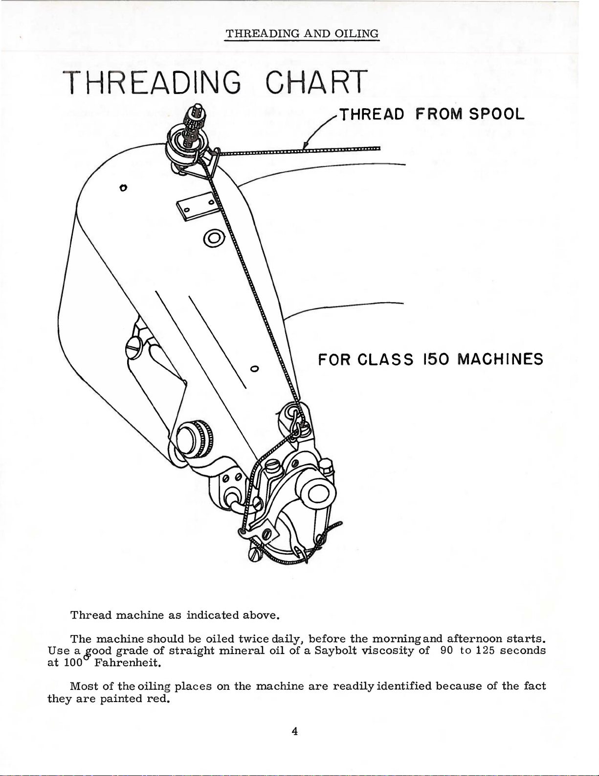
Thread
turn
hand whe
machine
as
indicated
el
in
operating
on
threading
direction
diagram
3
until the ne
on
next pag
edle
carrier
e.
is
in
its
Page 4
THREADING
AND
OILING
TH
RE
ADING
CHART
THREAD
FOR
CLASS
FROM
150
MACHINES
SPOOL
Thread
The
Use a &ood
at
100
Most
they
are
machine
machine
grade
Fahrenheit.
of
the
painted
should
oiling places
red.
as
of
straight
indicated
be
oiled
mineral
on
above.
twice
the
daily,
oil
of a Saybolt
machine
4
before
are
readily
the
morning
viscosity
identified
and
of
because
afternoon
90
to
125
starts.
seconds
of
the
fact
Page 5
ADJUSTING
INSTRUCTIONS
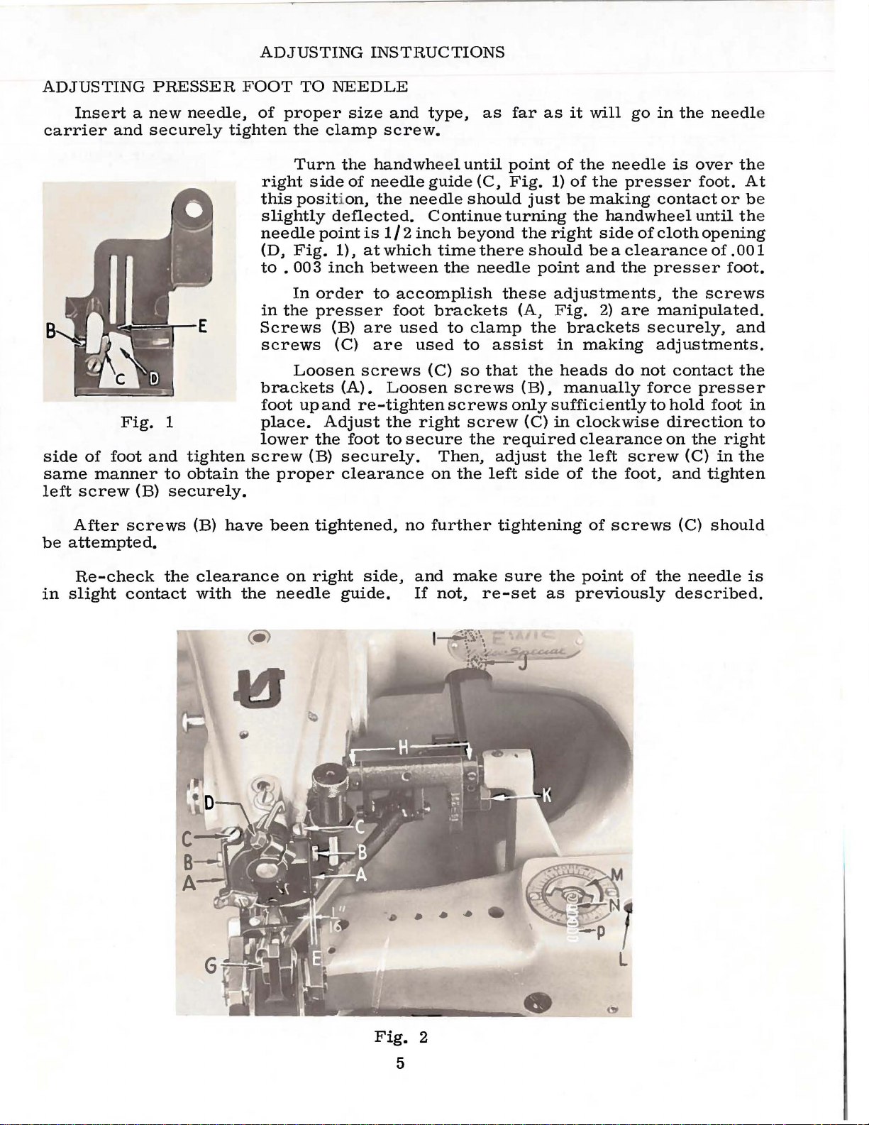
ADJUSTING
Insert a new
carrier
side
same
left
of
foot
manner
screw
and
Fig.
PRESSER
securely
1
and
tighten
to
(B)
securely.
needle,
tighten
obtain
FOOT
of
right
this
slightly
needle
(D,
to
in
Screws
screws
brackets
foot
place.
lower
screw
the
proper
TO
NEEDLE
proper
the
clamp
Turn
side
position,
deflected.
point
Fig.
.
003
inch
In
order
the
presser
(B)
(C)
Loosen
up
and
Adjust
the
(B)
size
and
screw.
the
handwheel
of
needle
the
is
1/2
1),
at
which
between
to
foot
are
are
screws
(A).
securely.
clearance
Loosen
re-tighten
the
foot
to
type,
until
guide
needle
inch
accomplish
used
used
right
secure
should
Continue
beyond
time
the
brackets
to
clamp
to
(C)
so
screws
screws
screw
the
Then,
on
the
as
far
point
(C,
Fig.
turning
there
needle
these
(A,
assist
that
only
required
adjust
left
as
it
of
1)
of
just
be
the
the
right
should
point
adjustments,
Fig.
the
brackets
in
the
heads
(B),
manually
sufficiently
(C)
in
the
side
of
will
go
in
the
needle
the
presser
making
handwheel
side
be a clearance
and
2)
making
do
clockwise
clearance
left
the
contact
of
cloth
the
presser
are
manipulated.
securely,
adjustments.
not
force
to
direction
on
screw
foot,
the
needl
is
over the
foot.
until the
opening
of
the
screws
contact
presser
hold
foot
the
(C)
and
tighten
or
.001
foot.
and
the
right
in
the
e
At
be
in
to
After
be
attempted.
Re-check
in
slight
screws
the
contact
(B)
have
clearance
with
the
been
on
needle
tightened,
right
side,
guide.
no
and
If
.
further
make
not,
..
...
tightening
sure
re-set
of
the
point
as
previously
screws
of
the
(C)
should
needle
described.
is
Fig.
2
5
Page 6

ADJUSTING
INSTRUCTIONS
(Continued)
POSITIONING
Turn
extreme
the
needle
the
presser
To
allow
the
above
Turn
extreme
right
If
have
needle
screw
top
of
stud
to
15
the
ball
check
the
left
previously
retard
obtain
the
edge
this
to
at
in
head
{,A,
to
the
the
left
groove
carrier
setting
the
right
(E,
is
be
adjusted
its
the
(A,
Fig.
the
stud
position
side
described.
or
advance
foot.
results.
THE
NEEDLE
handwheel
position.
(B,
this
adjustment,
to
is
obtained.
handwheel
position.
Fig.
not
2)
the
in
extreme
needle
Fig.
4)
right
so
crank,
3).
that
of
down.
of
of
looper
this
in
In
this
Fig.
be
1)
moved
in
The
of
the
case,
the
following
left
the
position,
accessible
Turn
the
lower
vertical
Re-tighten
the
needle
opening
It
may
adjustment
operating
position
and
even
loosen
by
taping.
operating
point
presser
travel
manner.
the
needle
end
with
the
clamp
point
in
the
be
necessary
to
direction
the
with
needle
direction
of
needle
foot.
of
the
loosen
through
eccentric
of
its
punch
screw
in
presser
obtain
until
needle
the
left
clamp
Re-tighten
until
should
needle
the
With
clamp
will-
the
hole
balJ
slot
is
10
marks
and
re-
relation
foot
as
to
slightly
desired
point
side
screw
clamp
be
on
in
to
the
should
the
1/16
needle
of
the
(D,
Fig.
screw
needle
be
looper
inch
has
in
2)
(D,
has
from
reached
the
opening
just
Fig.
reached
center
enough
2) when
the
upper
the
of
in
to
the
CAUTION!
stud,
shaft
make
crank.
TIMING AND
is
Turn
at
the
the
bottom.
When
sure
adjusting
that
ADJUSTING
Fi
g. 4
handwheel
it
is
LOOPER
in
operating
the
needle
seated
needle
enters
loop
in
its
there
holder
and
(A,
eccentric
against
The
looper
motion
the
of
needle
Under
the
following
Insert
shank
is
1/64
(Fig.
In
the
on
the
Fig.
direction
ball
the
needle
motion
so
that
spot
of
the
thread
normal
conditions,
manner.
the
looper
corresponds
inch
5).
left
end
of
looper
5).
until
the
is
the
needle
is
being
in
its
with
space
the
main
crank,
"V
timed
long
at
formed.
this
holder
flat
on
between
shaft
there
1
groove
Fig.
in
relation
prong
the
of
time
timing
so
that
holder
looper
is
a
is a timing
in
the
3
the
the
is
the
and
seat
11 V 1
main
to
the
looper
largest
adjusted
flat
on
so
that
and
groove,
line
sha
ft
Loosen
so
that
shaft.
its
This
the
two
timing
settin
set screws
line
coincides
g
will
be
in
the
with
satisfactory
looper
the
for
6
crank
right
average
edge
(B,
Fig.
of
the
conditions.
4)
"V
and
1
position
groove
in
the
the
crank
main
Page 7

ADJUSTING
INSTRUCTIONS
(Continued)
Variations in
advance or reta
Again,
is
over
clear
of
the
presser
On
clear
return
The
sleeve
the
the
turn the
the
spot
spot
needle
foot
continuing
stroke,
adjustment
and
eye,
(E,
right
the
materials
rd
this timing
handwheel
in the
in
the
and
Fig.
the
side
should
of
looper
needle.
needle
the
1)
rotation
of
the
enter
the
holder
and
and
short
by
no
looper
looper
connecting
threads
to
obtain
in
operating
At
this
be
prong
more
of
the
opening
the
crotch
is
used
the
direction
point,
from
1/16
of
the
than
1/32
handwheel,
in
of
secured
rod.
may
desired
the
long
to
3/32
looper
inch
the
the
presser
the
looper
by
manipulation
Fig.
and
of
Lateral
loosening
pulling
Vertical
secured
make
results.
until
.
short
The
vertical
prong
inch
should
midway
looper
5)
positions
also
the
by
the
foot,
provides
adjustment
it
necessary
long
of
the
to
the
left
clear
prong
the
adjusting
or
turning
of
and
between
of
the
adjusting
the
or
clamp
height
prong
looper
of
the
the
the
looper
looper
a
limited
height
is
sleeve
adjustment
the
to
of
the
should
the
inner
bridge
looper
needle,
the
adjusting
sleeve
laterally,
adjustment.
secured
screw
in
sleeve.
slightl
looper
just
end
of
the
should
on
its
prongs.
(B,
amount
by
(C)
and
or
out.
is
y
in
the
looper
the
looper
required,
adjustment
REAR
operating
moving
the
foot.
of
The
to
is
inch.
To
right
the
feed
the
made
FEED
set
to
Set
feed
bottom
connecting
to
the
it
can
of
both
POINT
the
direction
the
edge
the
rear
point
surface
of
with
the
desired
be
rear
left
of
is
the
Fig.
secured
the
connecting
feed,
until
and
the
feed
1/4
should
presser
stitch
5
rod
height.
turn
the
is
cloth
point
inch
be
length
yoke
by
turning
point
1/16
opening
so
in
flush
foot.
(D)
If
rod
the
inch
that
back
set
and
by
turning
only a slight
the
adjusting
and
adjusting
handwheel
of
the
needle
to
the
in
the· presser
the
short
of
the
with
at
This
7
and
adjustment
stitches
The
looper
also
adjusts
to a greater
sleeve.
If
the
adjustment,
made
right
needle.
parallel
the
amount
sleeve.
sleeve.
in
the
prong
per
by
loosening
connecting
is
of
holder
the
looper
extent
looper
the
of
Final
than
is
initial
the
rod
height
setting
connecting
vertically,
the
adjusting
radically
adjustment
clamp
{E),
adjustment
involves
rod
but
out
of
is
screw
rolling
is
The
(A,
arm.
feed
Fig.
6)
holding
point
is
adjusted
the
feed
by
point
means
to
the
of
7
two
feed
screws
driving
Fig.
6
Page 8

FEE
D P
LATEN
ADJUS
TING
INSTR
UCTIONS (Continued)
When the feed point
a
gai
nst the
The
tension
on
There
the
needle
will
not
Check
needle
penetrates
Pressure
controlled
the
cylinder
platen
the
must
makes
be
formed
to
by
bottom
platen
see
on
the
(A,
counterclockwise
clockwise
RIDGE
The
should
opening
as
noted
Adjustment
to
the
ridge
distance
the
small
is
1/16
directly
acts
FORMING
yielding
be
located
in
the
in
subsequent
11
•
right,
the
former
from
radius
inch
over
the
presser
As
should
the
when
the
of the pre
is
controlled
be
enough
its
for
that
material.
the
two
Fig.
increases
reverse.
DISC
ridge
in
the
forward
point
of
the
the
disc.
is
on
its
feeding strok
sser
by
two
will
compensate
pressure
penetration.
the
looper,
the
feed
feed
nuts
in
the
7).
Turning
the
forming
the
center
foot
and
platen
applied
If
resulting
platen
back
them
tension,
disc
of
the
folder,
paragraph 11Folder
needle
be
position
set
of
the
nose
needle
is
traveling
so
that
needle
on
the
point
of
the
the
disc
e,
foot
springs
for
and feed
which
varying
to keep
the
material
in
skipped
clamps a piece
is
of
to
is
the
feed
point
should
thicknesses
the
material
moves
stitches.
of
newspaper
platen
under
be
adjusted
of
with
presses
spring
material.
from
the
moving
needle,
before
the
pressure.
so
that the
a
point
work
when
loop
of
E
NOTE:
forming
end
there
play
is
disc,
in
end
pages 9 and
In
order
the
set
screw
crank,
direction
center
center
nose
crank;
take
plate
ridge
disc
in
accessible
of
of
of
up
all
If
there
holders,
forming
assembly,
the
ridge
until
the
also
firmly.
Before
be
the
play
10.
to
adjust
(F,
the
the
presser
the
presser
disc
the
the
end
is a need
remove
disc
care
forming
adjusting
sure
cradle
see
Catalog
Fig.
through
point
and
set
play
assembly.
must
disc
that
(H.
the
7)
of
foot.
foot
the
screw
in
to
remove
the
the
there
Fig.
No.
disc,
in
the
the
the
needle,
Position
and
point
(F,
the
ridge
nut
(B,
be
taken
holder.
ridge
is
no
7).
If
194-5,
loosen
collar
hole
(L,
when
the
there
of
Fig.
is
the
7)
forming
the
ridge
Fig.
Remember
so
that
Then
(G,
Fig.
Fig.
2).
traveling
disc
manually
1/16
inch
needle.
in
collar
disc
forming
8)
on
the
when
the
key
re-assemble
8
7);
also
Turn
to
the
the
so
between
Re-tighten
(G,
Fig.
shaft.
disc
assembly,
ridge
former
re-assembling
in
the
flange
the
nut
Fig.
the
7
clamp
handwheel
right,
that
the
the
7)
is
it
small
clamp
and
shaft
the
engages
(B,
Fig.
screw
in
in
line
lines
radius
screw
set
the
depress
and
ridge
with
8)
in
operating
with
up
with
of
in
collar
the
remove
forming
the
and
tighten
the
the
the
the
the
to
feed
the
slot
Page 9

ADJUSTING
INSTRUCTIONS
(Continued)
P ressur
plunger
Generally~
be
tween the
shaft
RIDGE
(Fig.
FORMING
The
lowers
being
depth
sewn.
of
forming
in
place.
e is
rod
(C~
the correct
8).
dialed
the
ridge
needle
disc.
F
top
regulator
The
penetration.
Re-assemble
directly
ig.
8)
of
the
DISC
forminR
word
Fig.
applied
with
the
to
upper
pressure
plunger
holder
REGULATOR
(M~
Fig.
disc
More"
to
indicates
8
the
set
the
nut
is
obtained
and
2)
located
get
screw
yielding
(D)
and
the
the
correct
more
ridge
locking
when
underside
on
top
depth~
amount
in
from
disc.
turninR
in
possible
regulator.
over
and
the
the
(N,
Fig.
the
the
mounted
the
(N)
and
forming
in
there
of
the
needle
and
The
order
striking
The
the
The
the
ridge
case~
Fig.
2)
cradle
ridge
needle
set
disc
place
is
5/32
of
the
head
cylinder
penetration
"Less"
regulator
that
the
to
protect
adjustment
the
regulator
More"
to
stop
needle
the
center
needle
former.
remove
2)
and
underneath
(H~
forming
and
adjust
just
tightly
by
adjusting the
with
lower
inch
of
base
in
indicates
also
disc
can
the
needle
the
ridge
direction
pin
inside
point
of
the
should
If
the
adjust
that
Fig.
disc
screw
grazes
to
lock
nut
clearanc
the
plunger
raises
the
limits
be
forming
is
made
(M~
as
should
just
this
set
screw
contacts
7)
in
shaft
the
screw
(E).
and
work
less
the
raised
point
Fig.
far
of
the
rid
g e
graze
is
not
screw
(P~
which
so
that
rid
ge
(P)
e
by
2)
as
be
is
FOLDER
The
the
center
With
height
the
relationship.
needle
Rotate
extreme
mately
1/16
increasing
tighten
center
knife
should
the
over
block
be
NOTE:
the
opening
the
folder.
ADJUSTMENT
folder
line
the
is
left
should
of
front
traveling
the
end
inch
the
1/16
folder
the
the
top
handwheel
of
stroke.
from
inch
with
ridge
mounting
taken
If
in
If
to
the
the
this
move
ridge
presser
is
be
set
needle
feed
The
needle
to
the
the
dimension.
the
former
screws
the
former
not
the
so
that
and
located
and
folder
point
right.
in
operating
Insert
needle.
two
locking
and
in
(C~
block
has
foot~
the
case~
its
front
in
the
removed,
should
direction
the
folder
A
slightly
With
the
screws
the
opening
Fig.
7)
and
perpendicular
been
rid
position
correctly
ge
former
9
ridge
edge
center
check
just
and
wider
folder
(B~
of
move
to
former
is
approximately
of
the
the
clear
and
the
position
position
belt
resting
Fig.
the
the
should
presser
the
line
set
7 ).
block
in
relation
line
accordingly.
opening
ridge
ridge
the
the
front
loop
can
on
If
the
foot,
accordingly.
of
feed.
up
with
1/16
in
presser
former
forming
needle
edge
be
the
ridge
folder
loosen
to
the
the
inch
from
-
needle
disc
at
approxi-
obtained
former
does
the
Care
center
center
foot.
as
the
by
not
two
of
of
Page 10

A
DJUSTING
INSTRUCTIONS
(
ontinu
d)
FRONT
TOI
Ass
curely.
Release
clockwise.
Insert
•
003
inch
Apply
folder
of
the
base.
slot
The
obtain
this
NOTE:
the
main
Fig.
free
2)
of
in
any
direction,
maintained.
The
travel
position
slot.
loosen
the
lower
top
4
1/8
slot..
If
lock
feed
driving
of
the
S.P.I.
the
of
it
Normally,
With
the
driving
adjust
the
FEED
mble
front f ed
a
piece
clearance.
finger
While
in
the
center
setting,
It
may
shaft
the
when
eccentric
binds.
locates
of
the
feed
is
desirable
nut
(K,
rocker
arm
slot,
When
stitch
the
arm
arm located
feed
lift
feed
arm
of
pressure
doing
feed
dog.
prong
adjust
be
making
The
on a flat
the
front
driving
to
Fig.
slot.
in
slot.
the sti
the
length
is
set
as
follows:
to
feed
pressure
paper
to
between
the
so,
Tighten
of
feed
two
necessary
the
and
position
first
on
feed
arm
increase
2)
and
raise
To
shorten
When
tch
length
arm
is
is
approximately
in
the
in
the
arm
top
feed
raise
should
collars
to
above
screw
the
is
regulated
in
the
the sti
the
is
at
the
center
desired
with
by
rotating
feed
feed
screw
be
on
adjust
dog
dog
shank.
bar
securely
located
feed
top
screw
so
rocker
front
adjustment.
eccentric
(I),
when
main
so
shaft.
by
feed
driving
stitch
arm
tch
rocker
length,
arm
length
is
at
approximately
bottom
of
8 S.
of
the
slot.
position,
(G,
adjusting
and
folder to
holding
that
screw
in
in
center
feed
that
turning
It
is
the
in
..
the
the
P.
I.
Fig.
knob
this
(H.
Fig.
drive
Loosen
the
feed
the
essential
2).
Do
(B.
obtain
the
feed
(G,
Fi
g.
position.
of
opening
2)
accordingly.
eccentric
the
two
drive
handwheel
that
not tighten
Fig.
6)
counter-
approximately
dog
flat against
2)
is
at
the
in
folder.
located
screws
strap
this
operates
in
operating
timing
(I,
se-
top
To
on
J,
be
_"{otate
in
the
center
feeddog
gulating
underside
connecting
the
feed
Re-apply
justing
handwheel
of
3/32
block
of
rod
driving
knob
its
travel
to
1/8
(A,
Fig.
the
feed
regulator
arm.
sufficient
(B.
Fig.
until
inch
driving
Lock
6)
the
toward
and
9)
so
block
tension
to
insure
top
the
slide
that
arm..
in
this
front
operator.
the
it
(B
..
position.
to
feed
feed
feed
contacts
and
Fig.
bar
proper
dog
Raise
lift
locate
9)
against
by
feeding
is
re-
the
the
adaction.
TRIMMING
The
for
the
size
of
Referto
width
of
MECHANISM
width
upper
the
folder
chart
finished
of
and
belt
trim
lower
being
on
loops,
is
used
Page
determined
knives.
and
the
15
for
weight
The
material
the
parts
of
material
by
the
selection
to
use
of
being
be
removed
or
of
these
sewn.
type
10
spacer
spacers
of
folder.
and
Fig.
pins
added
and
is
9
spac
relative
when
er
plates
to
the
changing
Page 11

PPE
H KNI
VES
ADJUSTING
INSTRUCTIONS
(Continued}
Attach
attaching scr
pressure
space
NOTE:
no
gap
Adjust
tension
to
between
between
Fig.
10
applied
upp
er
ews (C,
the
chip
top
The
chip
the
tension
may
knives,
Fig.
deflector
of
folder
deflectors
deflectors
It
the
upper
slightly.
possible,
LOWER
Turn
stroke.
position
(The
resharpening.
turn
above
on
vary
elongated
Loosen
connecting
bottom
knives
with
chip
6 & 10}.
and
should
deflector,
and
cutting
should
and
knives
Normally
to
give
KNIVES
handwheel
Loosen
knives
nuts
by
turning
the
thickness
When
knives
the
upper
be
noted
from
maximum
knife
to
slots
}
on
rod
edge
and
securing
and
edges
be
assembled
knives.
that
the
the
clockwise
attaching
their
in
ball
until
of
top
two
of
correct
knives,
lock
in
place.
of
the
knives.
the
location
top
of
knives
clearance.
until
maximum
the
knives
joint
front
knife.
screws
cloth
connecting
edge
to
spacing
to
the
the
folder
are
positioned
lower
screws
low
of
lower
Tighten
(E,
Fig. 6 }.
be
trimmed.
plates
apply a slight
This
are
will
knife
position
of
the
base
knives
(D,
to
rod
nuts.
block
Fig.
knife
cutting
and
compensate
(D,
The
with
insure
so
can
be
as
far
are
6 & 10}
retighten.
Fig.
is
1/32
amount
four
upward
proper
there
edge
varied
up
at
top
7}
inch
is
of
as
of
and
for
and
of
Proper
the
collar
operate
collar
STITCH
The
near
shaft
down,
dow
shorten
ing
Release
n,
to
the
with
the
alignment
(E,
the
machine
in
position,
LENGTH
stitch
head.
numerals
which
turn
the
desired
the
the
stitch.
Fig. 7 }.
length
Open
will
knob.
engage
handwheel
amount
of
slowly.
being
is
the
which
As
you
Stitch
the
bottom
To
obtain
The
careful
regulated
top
cover
indicate
a
slot
away
turn,
of
stitches
range
knives
the
correct
knives
not
to
by
the
on
the
the
in
the
from
observe
per
of
the
to
will
disturb
knob
arm
number
feed
you
to
the
inch
machine
the
top
knives
alignment,
automatically
the
alignment.
(B,
Fig.
and
observe
of
stitches
mechanism.
lengthen
indicator
appears
is
until
from
is
obtained
loosen
align
3}
on
the
the
per
While
the
stitch
the
directly
6
to 8 stitches
collar
themselves.
arm
feed
inch.
number
under
of
indicator
Press
holding
and
by
positioning
screw
the
machine
the
the
toward
correspond-
the
indicator.
per
Lock
on
knob
knob
you
inch.
and
the
to
11
Page 12

3575
20-80
1
48-1
89
T
F
80
22- 321
- 20
.,
0
0
8-138
12
Page 13

The p
arts illustrat
r e pr es e nt
the
parts
ed
that
on the
are
preceding and following page,
used
on
Styl
e 150- 200
but are not used
that are d
on
escribed
Style
on
150-20.
this page
and
on page
15
On lhe prece
low
or be
ain
assembly.
m
·se C
atalo
P
art
No.
8-137
8-138
14-394
14-432
'~18-
400
18-533
t-<18-
533
18-764
18-873
18-951
18-1075
20-80
20-148
20-149
21-58
21-427
22-262
22-319
22-320
22-321
32-36
*
32-302
33-156
18-700
39-141
45-464
46-201
47-132
48-180
50-286
50-287
*
57-52
70-73
107-44
*
110-
285
*
110-314
115-160
115-161
119-81
119-82
AS126
158-26
158-27
444-318
18-318
20-122
21-341
26-1
52
44-318
99-304
667
D-24
*
1158
L
*
1160
L
~
'1750
L
*6042
A
22652
35751
D-12
F
*
88
89
38242
G
39543
N
*
20-
31
ding page,
the
box
g N
o. 194-5 for
A
<
part
are
ge Form
g Sc
numbers
indicated
all
parts
Sh
aft-----for
for
for
rew,
for
for
for
for
14-394----
for
18-1075--
g N
ut,
on
Sprin
Sprin
on
left-right
er
Shaft---
119-68
45-464
3 824 2 G - - - - -
for
115158-27
47-132----- - ------
for
g, for
g- - - -
and
Knife Guard,
Knife Guard,
Rid
~ain
Screw,
Screw,
Screw,
Plu
Screw,
Screw,
Screw,
Nut,
Nut,
Lockin
Tensi
Presser
Spring Pin------Presser
Pin,
P in,
Arm
Cover,
Auxiliary
Pin-----
for
driving lower
for
driving
Cover
Plate-----
for
50-286-------
Feed
Driving
Screw------
Drive
P in
Front
Front
Connect
Driving Crank,
Knife
Spring Support
Handwheel------------
Collar
Feed
Feed
ing
Support
Bar-------Rocker
Rod
Bracket
Bracket -----
Spring Barrel---------------Flange,
Top
Top
F e
Connect
Bottom
Bottom
\Va s h e
S
lide Plate,
Slide
Rid
Knife
Kni
fe
ed
Lift Reg
r,
Plate, rig
ge
Former
for
rid
ge
Spacing Plate,
Spacing
ulator
ing
Rod
Knife,
left-----------------
Knife, rig
for
18-873-
left---------
ht----------------------------------------
Assembly---------
Screw-------------------
Nut
-------------
Spring------------------
Plunger-------------Di
sc--------
Disc
Front
Screw,
Nut,
Screw,
\V
asher,
Screw,
Looper
Feed
Thrust
Nut,
Plunger
Feed
Rocker Shaft--------
for
50-287------------
for
865 L ----------------
for
119-68
for
22652
for
50-286
Rocker
Set
Screw----------------------------
Spot
Rocker
Shaft
Screw
Shaft--------------------------------------------------------
Bearing Washer,
for
No.
4118-15
contain
not illustrated
160
ed
this page
within
by
- - ---- ------
---------
---
----on Sty
- - - -
- - - ----
---
- - - -
le
150-200-5/16------------------
-- --
- - - - -
----
machine arm-
- --------
- ---- -
----
- - ----
---
- -------------
70-73--------
low
er
---
knives --------------------------
- - - - - - - ---- - - - -
a box
are
indentin
and describ
D
g the
escrip
components
ir desc
riptions
ed her e.
tion
- ---- ----------------
----
- - - - - - --
------
-----------
-------
- -- -------- - - -
-----
---
- - - - --
---
- ----------------------- ----------------
- - - - - - - - ------------
- -
------ ------------------------------------
--------------------
----------------------
- - - - - - -
---------------------------
------------------------------------
--------------
----------------------------------
- --------
- -------------------------
- - ---------- - - - - - - -
- ·
---
----------------------
----
----
- ----------------------------
----------- ------------------------
- --------knives,
lower
knive
--
---------
-
-------
---
- -
---
-----
-------------
on Style 150-200-3/8--------
s,
on
Style
150-200-5/16---------
- - - - -
---------------------------
- - -
---------------------
Eccentric ---------------------------
-
-------------
------
-----
--
---
- - -
----
----------------------------------------
for low
er
knives----
- -
---------
---
former
shaft---------------------------------------------
for
Plate,
for
- - - - ----
----------------------
----------------------------------------------
------
---
----
---
- - -
----------
- - -
- -------
----------
- - - - -----------------------------------------
--
----
---
-----------------------
----------------
--------------------------
---------------------------------
-
-----------------------------------
- -
---------------------------------
Style 150-200-5/.16----------------------------Sty
le
150-200-3/8------------------------------
------------------------------------------------------
Regulator
ht
-
------------
Holder--------
on
D-12
--------------------------------------------------------
Block
------------------------------------
--
-----------
- - -
--------------
-
-
-------
-
------------------------------------------
------------------------------------------------
-
----------------------------------------
-
-----------
- - - -----------------------------------------
-
------ -
- - - - ---------
- - -
----------------------------------------
-
-----------------------------------------
---
---------------------------------------
-
---------
- - -
Style
150-200-3/8--------------------------------
----------------------------------------
--------------------------------
Stop
Collar
-------------------------------------------
---------
- - ----
-
---------------------------
-------------------------------
-
-------------------------------
-------------------------------------
----------------------------------
-
---------------------------------
-
-------------------------------
-----------------------------------for
18-1075
-------------------------------
-------------------------------------------------
of
the
part
under
-
--------
-
-----------------
-
--------------
- -
-
------------------
-----
- - -- - -- -
-
----------------
-
-
--------------------
-
-------------------
--
----------------
- - -
-
----------------
-
------------------
-
-----------------
-
----------------
-
-----------------
-
--------------
number
listed
the description
-- -----------
- - -
-----------
---
----------
---------------
---------
---------------
-------------
-
--------
- - -
------------
-
------------
-
--------
-
---------
-
------
-
-
------
--
------
opposit
-
--
----
-
---
of
Am
Re
the
1
1
1
1
4
1
1
1
1
2
1
1
1
1
2
1
2
1
1
1
1
1
1
2
1
1
1
1
1
1
1
1
1
1
2
2
1
1
1
1
1
1
1
1
1
2
1
1
1
1
1
2
1
4
2
2
2
1
1
1
1
1
e
t .
q.
*Not
shown
on
the
picture
plate
on page
12.
13
Page 14

50-210
(.)
1132
1183 L
'
'./
I
L I
18-715
2
3-333
14
468-23
-1
Page 15

MISCE
LLANEOUS PART
S
Part
No
.
18-715
18-7
32
18-9
42
23-3
33
23-3
34
24-323
41-42
41-
4 9
50-210
405-
5 81
5-581
6-7
3
18-643
*
431-18
t431-185-
'~431-186-
t431-186-
468-23-1
468-2
1132
1160
1183
499-303
22894
below
to
sew
431-185-5116
5- 5/16
3/ 8
5/16
3/ 8
20-60
3
L
L
L
AB
If
a
customer des
indicates the
5
116
inch
.
Screw,
Screw,
Screw,
F
ront Feed
ee
F
Fee
d P
oint----
d P
late-------
for
for
for
ThreadGuide
ThreadGui
Fee
d P
Pr
late
esser F
Presser Foot
N
eedle
S
crew------
F
older,
F
older,
F
older,
F
older, mark
Tension
marked
marked "B", split
mark
Post, comple
N
ut--------- -----
Tens
ion
Tension S
Nut-
-----------------------------
Tension Dis
F
eed Plate Holder,
Screw,
parts to
belt
for
ires
to sew a different
be
loops
made
Descriptio
23-333
23-334
499-303
-----------------
-----------
--------------------
-
-------
Point---------------------
- ---- -
------------------
--
-- --
- -
---------------
-------------------------
de
- -- - - -
Holder Bracket--------------
oot,
Guide-
-------------
complete----------------
(not
identified
- - ----
----------------------------- --
on picture pl
- - - - ----
-- --------------------
"A" , sp
ed "C
ed "
D", solid type,
",
lit
solid
type,
type,
type,
5/16
3/8
for
for
inch fini s
te-----------------------
Staf
f - ----
-------------
pring---------------
---------
-
---------
- ---- -
c------------------
right-----------
folder-------------
removed
of lig
ht
and
to
weight
added
medium weig
- - ----
material
to
a s
tanda
n
-
---
----------
- - - - ---- -
--
- - -
---
- -
--------
---
---
----- ----
---
- - ---- ------- ----
-------
-- --
- -
----
-----
ate)-
- - ----
---
- - -
------- --
- ------- ----
----------
----------
-----------
---
- - - - - ------- - - ------
-------
- -
----------
- - ---- -------- - -
i
nch finish,
for
Style
h, for Sty
5
116
in
ch
3/8
i
nch finish- - -
finish-
-- ----- ----- - - - -
----
- --------
- - -------------------
-
--------------------
-------------
-
-------------
- - - - -
---
---
ht
--------
- - - -----
- - ----
, a
diff
r d 15
material
---
------
- - - -
----
---
- -
-- -----
er e
nt
usin
fold
g a
0-200-5116
----
--------
- - - - -
- - ---------
- -
---
-------- -
- - - ---- - - -----
- - - - -
-----------
------ -
----
- - -
---
- - - -
----
------
----
---
- ---- -
15
0-200-5116---
le 15
0-200-31
- - - - -
----
- --------------
-- --
- - - - -
---
-----
- -
-----------
---- - ----------
- - - -
--------
-------------
- - -
--------
er
or fini
ma
sh,
chine th
split type folder,
Amt.
R
----
- 1
---
------- 1
- 1
-----
---
- 1
- - 1
-----
------
- - -
- 1
--
--
8- - - - - 1
----
- -
---
- 1
----
- -
--
- 1
- -- 1
- 2
---
--
the chart
at
is
set
No.
eq.
1
1
1
1
1
1
1
1
1
1
1
1
1
2
up
Type
of
Material
Light
Light
to M
ed.
to Med. 43
Light to l\Ied.
Solid Fold
Ex
tr a L ig
ht
Split Fold
Extra Light 43
Solid F
Extra
Hea
vy
431-185-3/
:\
Split Folder
Extra He
avy
43
M
Solid Fold
Folder
431-185-318
M
arked
Split
fark
Solid
431-186-318
arked "D"
M
"B"
Folde
r
1-186-5116
ed
"C"
Fol
der
er
431-185-5/16
Marked "A "
er
1-186-5/16
M
arked "C"
old
er (1) 43
'la
rked
"B"
1-1 8 6-
arked
31 8
"D"
er
Fini
sh
318"
5116"
318"
11
5
116
11
5116
8
31 8"
318"
Remov
(4)
18-400
(1)
22-
(2)
(1)
(1)
(4)
(1)
(2)
(1) 43
(2)
(1)
(2)
(1)
(4) 18-400
(l)
(4) 18- 4
(1) 43
321
110-285
431-185-5116
431-18
18-400
22-321
110-28
1-185-5116
110-285
22-321
110-28
22-
321
1-1
431-185-5/16
00
1-18
e F
-5116
5 (2)
5
85- 5
116
5- 5/ 16
it
Wit
(4)
1750
(1)
22-320
(2)
110-31
(1}
431-18
o > 431-
(4)
(1}
< 1 >
(2}
(1}
(2}
(1)
(1)
(4}
(1}
(4)
(1)
186-
1750
22-320
110-314
431-186-
110-
314
22-320
110-314
22-320
431-186-5/16
1750
4
31-1
1750
431-186-
L
4
5- 3
L
L
85- 3
L
h
51 16
31
/8
3/ 8
/8
8
*
Folder
t
Folder can be used
can
be
used for
fo r lig
ext
ra lig
ht
and
ht and l'ght
medium
or xtra heavy weight
to medi
um weig
ht material, de
m ater i a
15
pend
ing
l, depending
on shim
on shi
s used .
ms use
d .
Page 16

_.o
...
..
'
0
WORLD'S
p.llf
FINEST
QUALITY
*
INDUSTRIAL
SEWING
MACHINES
UNION
SPECIAL
facilities throughout
aid
you
in
the selection of the right sewing
equipment for your
Special representatives
tory trained
promptly
tion, there
and
and
is
a Union Special Representative to
serve you. Check with
ATLANTA,
BOSTON, MASS.
CHICAGO,
DALLAS,
LOS ANGELES, CAL.
NEW
PHILADELPHIA,
GA.
ILL.
TEXAS
YORK, N.
Y.
PA.
maintains sales
the
world. These offices
and
service
will
particular operation. Union
and
are
service men
able
to serve your needs
are
fac-
efficiently. Whatever your loca-
him
today.
MONTREAL, CANADA
TORONTO, CANADA
BRUSSELS,
LEICESTER,
LONDON, ENGLAND
PARIS, FRANCE
STUnGART,
BELGIUM
ENGLAND
GERMANY
Representatives
industrial
UNION SPECIAL
400
N.
FRANKLIN
and
cities
distributors
throughout
ST.,
In
all
Important
the
world.
CORPORATION
CHICAGO,
ILL.
60610
 Loading...