

Page 1
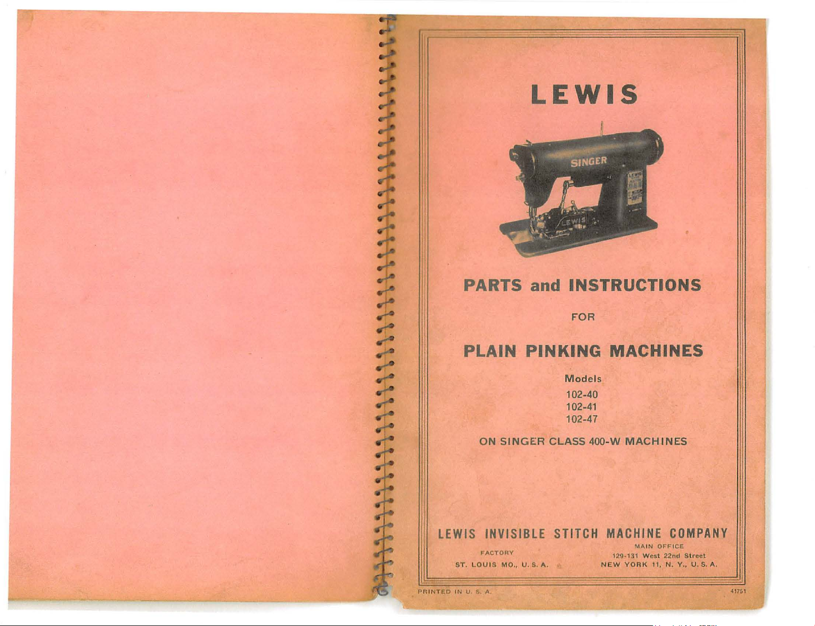
LEWIS
PARTS and INSTRUCTIONS
FOR
PR
I
I NT
PLAIN
LEWIS
ED
IN U.
PINKING
ON
SING
ER
INVISIBLE S
F'ACTORY
UIS MO.
S.
A,
, U
.S.
CLASS
TITCH
A.
M o
del
102-40
102-41
102-47
400-W
MACHINES
s
MACHINES
MACHINE
MA
12
9·13
NEW YORK 11,
1 W
COMPANY
I N OF'F'I
CE
est 22nd Street
N.
Y.,
U.S.
A.
417S1
Page 2
INSTRUCTIONS
ADJUSTING THE
THE
CATALOGUE:
T o
order
refer
to
drawing.
dash,
thus
(50-E),
par
ts
that
might
part
for
the
particular
required
GENERAL:
with a male
makes
upper and lower
upper
mechanisms
machine
.
The
Lewis
and
The
parts
of
sewing
shaft bracket, pres
are
heads
P L
AIN PINKING
the
correct
If
the number
this
be
used. Refer
Class
female
are
arranged
machines,
Knives
arranged
.
FOR
LEWIS
part
means
Pinking
cutting
in cutting
there
102
Pink
with a base
ser
foot
to
fit
OPERATING
CLASS
MACHINE
for a given
has a letter
are
several
to
parts
Model
knife.
for
for
er
is a "V"
the .various
relation
and
other
on
the standard
for
AND
102
Model
following the
differen
list
for
which
Knife
holding
to
each
stitching
the
standard
sewing
the
pinker
t h e
other,
Number
t
correct
part
is
an
OIL:
Oil
front and rea
of
lever
bearings
hook
as
indicated
base, under
SHAFT
b y
back
gear
lash
BRACKET:
The
fastened
The
and
all
moving
r,
also
the
lower knife.
pinking
shaft
wear
parts
two
and
knife
by arrow
mechanism
on
to
the
bracket
between
once a day,
oil
holes
holder
marked
main
is adjus
the
for
lubricating both
shaft.
"OIL"
driving
shaft
by
table
in
driving
oil
knife
Oil
sewing machine
on
top
shaft
is
two set
order
and
driven
Lever
o·f
pinker
gear
screws.
to
take
gea
shaft
sides
driven
up
rs.
Page 3
l
BASE:
bed
by a screw
Class
base
to
the
UPPER
be
placed
the
lower
The
machines
to
be
bottom
KNIFE:
To
in
end
base
set
of
adjust
the
of
is
#18-501
through
for
various
the
the
knife
knife
fastened
on
an
pink.
top
knife
holder
holder.
firmly
95
Class,
elongated
widths
lever, a new
and
from
set
to
and
slot
the
the
#18-351
the
knife
sewing
which
line
upper
1/8"
machine
on
allows
of
stitching
knife
400W
below
the
must
the
bed
of
base
of
the
and
chips.
TO
REMOVE THE
Move
cu
tting
position,
be
removed. To
proceedings.
TO
REMOVE
the
cutting
handle
sewing
Remove
replace
THE
machine
devise
TOP
KNIFE:
#4
76-11
LOWER
has
screw
the
KNIFE:
as
been
so
top
well
wiped
that
knife
#18-544,
knife,
as
the bottom
clean
is
and
reverse
in
the
top
of
knife
the
of
the
all lint
non-
above
3
can
locknuts,
knife
has
turn
the
1/32"
the
TIMING
above
be
loosening
the
sewing
described
sewing
TO
MACHINE:
sc
ba
co
then
is
and
p
two
the
just
top
REMOVE
rews
ll
joint,
nnecting
the
not
threaded).
lift
rocedure
below
pinker
machine
machine
Rotate
the
In
Adjust
locknuts
When
starting
#18
ball
the
turn
the
assumed
connecting
the
KNIVES:
the
cutting
to
the
set
shaft;
above,
THE
the
-500, appearing
faces
the
rod
forward
joint
cutting
replacing
outlined
connecting-rod
machine
the
extreme
rod
until
top
edge
of
firmly.
cutting
edge
screws
until
No
feeding.
sewing
can
Remove
edge
of
the
feed;
the
#1025
now
rotate
the
feed
cutting
PINKING
machine
operator; loosen
towards the
be
removed
the
mechanism
the
cutting
above.
in
sewing
the
the
of
lower
tim
is
action
BASE
in
the
pinking
from the
Be
sure,
b y
downward
point
lower
the
top
knife,
ing
is
that
hold
the
hand
in
the
is
FROM
hand
upper
head
from
me
cha
however,
loosening
direction
position,
of
the
upper
knife;
accomplished
to
these
base
nism,
then
knife
is
the
machine
the
driven
wheel
position
take
THE
wheel
shaft
holding
set
of
the
the
shaft
screw # 18-351,
machine.
reverse
the
until
tighten
about
of
the
as
place
SEWING
until
screws,
machine,
(the
to
see
two
the
now
knife
by
gear
with
the
the
that
1/16"
must
set
the
pull
ball
top
is
on
the
Remove
sewing
screws
remove
ceedings.
ADJUSTI
knives,
be
t
he
that
bring
upper
Now gently
or
edges
the
knife
RE
machine,
the lop
out lever #4
acting
machine
#18-558
knife.
To
NG
If,
when
assembled
#18-558
the
holding
the
cutting
knife
left until
of
the
lower
TURNING
knife. Ti
.
When
do
ball
upon
for
replace
KNIVES:
any
the
to
screws
is
just
press
an
equal
top
THE
the
not
joint
76-11
the
the
screw
forget to
knife.
pinking
as
described
that
hold
the
the
lower
reason,
knives
the
pinking
firmly. Then
edges
below
on
knife and the
ghten
PINKING
pinking
is
fastened
has
#18
into
the
space
been
it
are
-544
the
lower
both
device
see
devi
ce
above;
lower
knife,
is
desired
replaced,
device
is
contact
top
surface
knife
appears
inside
/118-558
DEVICE
is retu
that
securely,
released
from
remove
knife
reverse
first,
attach
at
the
so
to
between
edges
the
so
the
bed
the
on
to
the
to
remove
the
lower
but
do
the
top
top
of
that
the
of
the
move
it
the
of
the
screws
TO
THE
MACHINE:
rned
to
set
screw #18-500
also,
that
that
the spring is
of
the
hexagon
the
above
both
knife
not
knife so
the
slot;
point
low
er
to
the
cutting
opening
of
the
the
sewing
the
base
pro-
must
tighten
of
knife.
right
lower
throw
and
now,
the
in
for
Page 4

4
knife
the
knife
distance
when
machine.
the
machine,
the
upper
the
upper
machine
the
proper
sewing
lower
position
the
lower
into
the
greatly
avoid
hand
wheel
hook
.
Turn
is
in
its
so
that
from
the
device
Tighten
If
it
is
knife
knife
Now,
and
setting then
direction
position;
must
knife.
lower
lessened
damaging
very
the
hand
uppermost
the
the
top
was
the
necessary
measure
to
the
is
in
when
the
the
above
until
then,
be
about 1/32"
When
knife
and
the
slowly
wheel
point
surface
taken
upper
to
the
top
the
extreme
pinking
measurement
would
the
the
cutting
the
too
deeply,
the
top
hook
when
and
in
sewing
position;
of
the
of
from
knife
remove
distance
surface
device
be
knife
below
upper
knife
the
see
now,
top
the
the
firmly.
of
upward
to
stroke
point
knife
the
may
top
that
knife
lower
bed
the
from
the
is
has
turn
of
the
life
knife
the
direction
by
pressing
is
the
knife
of
the
pinking
the
lower
position.
returned
been
the
hand
is
at
its
the
knife
top
cutting
is
permitted
of
the
strike
is
top
knife
until
down
same
that
sewing
base
bottom
knives
the
point
knife
to
the
overlooked,
wheel
extreme
in
edge
to
hook.
set,
turn
clears
the
existed
from
when
in
this
of
enter
will
the
top
To
the
on
of
be
is
resharpened.
on
the
lightly,
removed.
be
touched
only.
SPRING
by
the
cutting
remedy
life
of
must
b e
NEEDLE
machine,
then
remove
The
side
of a grinding
and
the
minimum
The
inside
in
any
PRESSURE
The
pressure
knurled
clean, a slight
the
the
fault.
knife,
applied.
head
the
PLATE:
To
remove
remove
the
needle
top
of
the
wheel
amount
of
the
"V"
way -grind
ON
TOP
applied
screw #18-844.
increase
It
is
to
be
minimum
the
needle
the
pinking
plate
lower
and
of
of
the
top
KNIFE:
on
the
in
noted
amount
plate
base
as
usual.
knife
should
metal
the
low
surface
top
If
the
pressure
that
to
of
from
as
described
be
should
e r
knife
insure
spring
the
is
re-sharpened
touched
knife
of
the
is
controlled
knives
will
generally
pressure
sewing
above,
be
are
the
very
must
knife
long
5
not
not
and
RESHARPENING
It
will
edges, and
"V"
shape
sharpen
After
free
from all
burred
cutting
angle
angle
TO
SHARPEN
and does
that
When
of
the
grinding, the
and
edges
It
should
with
the
of
the
The
not
KNIVES:
be
noted
it
may
re-sharpening
the
knife,
end
of
the
burrs.
rough
of
back
ends.
edge
the
be noted
THE
low
er
knife
have
to
that
the
be
reversed.
the
which
knife
only
edges
must
Th
is
is
will
not
lower
of the. knife.
LOWER
that
as a rule,
be
resharpened
knife.
KNIFE:
top
knife
top
knife,
is
acc
urat
and
be
stoned
important
last
long
the ends
Do
will
has
do
ely
do
not
keen
inasmuch
and
of
the
not
change
out
last
whenever
two
cutting
not
destroy
made -re-
grind
the
and
smooth,
as
will
damage
knife
are
the
cutting
the
top
the
top
sides.
a
on
knife
knif
the
the
an
e
LEWIS
INVISIBLE
STITCH
MACHINE
CO.
Page 5

-
ARM
7
PARTS-
(f)
w
z
I:
u
<l:
:::i!:
(.!)
z
:::.::
z
Q_
z 0
<l:
_J
Q_
(f)
3:
w
_J
a::
0
u..
(f)
I-
a::
<l:
Q_
en
w
~
:X:
<..>
<t
::!:
3:
0
~
en
en
<t
..J
<..>
a::
w
<!)
~
en
a:
0
IL
®wiD:;:@
'
CONN,
ff"l·~~v
(\JQ)
__
(\J
PARTS
Lewis
8-66
8-
86
14-425(B)
14
-42
7(B)
18-246
18-261
18-391
1
8-500
18-566(A)
18-567
18
-792
18-810
18-857
1
8-858(A)
26-164
27-68
27-148
27-149
40-86
50-219(B)
50-220(B)
59-6
63
-22
63-24
67-10
71
-30
79-21
FOR
SINGER
Model
102-40
102-41
102-47
Guard
Guard
Shaft
Shaft
102-47.
Screws
Screws
Screws
Set
Screw
Models
Screws
Screws
Screws
Screws
Stop
Model
Plunger
Dri
102-40,
Driving
102-41
Idler
102-47.
Spring
Bracket
Bracket
102-47
Hex
Felt
Felt
Drip
Connecting
Class
Ball
Joints.
LEWIS
PLAIN
Mounted
CLASS
Numbers
on
Presser
on
Feed
Plate.
on
Bracket
in
Bracket
for
Guard
for Guard,
for
Ball
Screw
in
Shaft,
for adjusting Idler
102-40
for
for
for
for
Screw
and
adjusting
holding
holding
Clamping
in
Arm
102-41.
for
adj
usting Front
ven
Gear
on
Bracket
102-
4 1
and
Gear
on
and
102-47
Gear
for
Models,
Washer
under
under
for
Arm
Arm
.
Box
Wrench.
Oil
Oil
Pan,
Wick,
Wick,
for
for 99-
Models
Rod
for
Machines.
Stud
in
Ball
PINKING
on:
400W
Foot.
50-219,
50-220,
on
Presser
8-86.
Joint
14-178
102-
Gear
Bracket
Gears
to
102-47
Main
.
Edge
for
for
Bracket
102-40,
Knife
Joint,
MACHINES
Model
Models
Caps.
for
Gear
47.
Bracket.
under
to
Flange
ho
lder, 99-
locate
holder
Feed,
Shaft,
.
Shaft
for
102-40,
Guide.
Model
Models 102-
under
267
Holder
41 and 47.
Lev
for
all
MACHINES
Singer
Class
400W
4
00Wl01
400W30
102-41.
102-40
and
Foot.
79-21
Ball
Holder, 99-267,
Arm
.
.
267.
99-267,
102-47.
for
Models,
Models,
102-
4 1
102-40,
and
102-41.
40 a
nd
Arm.
.
er,
all
Singer
Upper
Ball
Stud.
Page 6

8
9
99
- 2
67
107-38
107-
49
4
05-429(C)
405
-523(C)
81
0
1005
1012
102
5
1027
'10
29
4124-24
PRESSER
405-43
SPECIAL
0
-ARM
Holder
Flange
Flange
Presser
95, 241-11 and 400W
Machines.
Presser
Singer 400W30
S
crews
107-16.
Set
Screw for
Nut
for
18-547
Set
Scr
Collar
Set
Scr
Upper
Machines.
FOR
ALL
Singer 400W Machines
FOOT
PARTS
for
br
for
Foot
Foot
for
adjusting
and
ews for
for
ews
Ball
AND
PLAIN
Idler Gear,
Idler
Driven
holding
71-30
Idler
for
Jqint
THREE
.
*
424-282
Sp
ecial Feed
to outsi
CON
Gear
Gear,
Complete,
Complete,
Machine.
Ball
79-
Screw
.
Driven Gea
Gear
Collar
complete,
PINKING
FEED
23
-132
de
of Pink.
'T-
Singer 400W Machines.
27-149.
27-68.
for all
machine
for
Driven
9.
18-556
Flange
1027.
ROW FEED
MACHINES
Plate. 1/
Singer Cla
s ,
except
Model 102-
Gear
to
and
rs.
Shaft,
for all
PARTS
FEED
2 "
Flange,
Singer
24-110
from Seam
400W30
47
18-858,
107-38.
PLATE*
ss
on
3- 61
14- 171
14-172
14-206
18
18-178
18-225
18-227
18-351
......
~
..+--
~
...:--
~
~
~
;,:
~
.;.--
.:.:-
,;:-
18-353
18-391
18-422
1818-547
1
18-5
182
21-30
21-367
22-1
23-124(B)
23-307(B)
23-308(B)
24-152(A)
24-164(A)
26+
34-26
40-46
40-57
40-10 1
45-247
45-248
45-249
46-108
79-9
99-134
- 71
544
8-558
96
844
1-2
69
67
164
-
BASE
PARTS
Pinker
Shaft
Shaft
Shaft
Screw
Screw
Screws
Screws
Screw
400W.
Screw
Screws
Screw
Screw
Sc
Screws
Base.
Screw
Pinker
Screw
Spring
9
Springs
Spring
102-47.
Hinge
Feed
machines, except
Front
Rear
Feed
400W
Feed
400W30
Plunger
102-47.
Cam for
Washer
Wa s
Spring
Lever
L e.
Lever
Li
Ball
Holder
Base Onl
for 45-2
for 99for
for 45for 99-
for Feed Plate
for
for Hold
for 99-
for
for
for
rew
for
for
for
Base.
for adjus
for
for
for Fro
Pin
, t
wo
Feed for
Feed
Pla
te for.
Machine.
P l
ate
Machine.
for
throwing
for
her
for
Washer
for
ver
for
fo r
nk
for
operating
Stud
for
4 7
134
throw
248 Lever
134 Holder
Feed.
ing
143,
Ball
holding
Clamping
leveling
holding
holding
Presser
Knife
nt
for
Presser
rows, all
1/4"
for
adjusting
Screw
Ball
operating
operating
Knife
for all L
Upp
er
out
tingte
l/4"
two
Model
for
-
y ,
400W.
Lever
Holder
Casing,
to
Joint
throw out
for
for
Handle
.
Pinker
for
Edge
475-68
119-25
Pinker Base
Lower
Edge
Guide
nsion
Foot.
Holder, 99-
Feed
adjusting
Foo
Singer
400W30
to
l/2"
1/2"
row
feed. Singer Class
102-47,
Left
out
Upper
18-35
44 7-23.
Tension
Upper
throw
thr
ow out
ower
Ball
Knife,
Upp
e r
Knife.
Upper
.
for
operating Cam
for
Upper
Base
to
Machine
Guide.
447-23
Pink, Model
1.
119-25.
.
Edge
Guide.
Upper
.
Knife
to Pinker
Holder
of
Springs, 21-
134.
pin
t .
Class
.
Hand
Knife
out
Cam,
400W
Pink,
on
Singer
Feed,
Knife.
Cam, 34- 2 6.
.
Cam.
34-26
Cam
.
Joints
Knife.
Knife.
Knife
to
in
base,
Model
102-47
Model
.
.
.
.
309.
102-47.
.
Class
Page 7

10
-
BASE
PARTS
CON'T
-
99-143
99-147
11
9-24
11 9-25
119-34
191-1
SBW
cs
23
869
1003
1005
1012
1160
1776
403-69
447-23
475-68
4
76-11
15
1
Holder,
Holder
Lower
Seam.
Upper
Lower
Button
feed,
Set
Nut
Nut,
ting
Set
Set
Nut
connecting
Nut
Bearing
Pinking
Machines.
Lower
Machines.
Edge
Handle
Knife.
Model
Screws
for
left
rod,
Screw
Screw
for locking
for
Guide.
swinging
on
Pinker
Knife
Knife
on
top
for
Cam,
hand
numbers
for
for
Rod
locking
Screws
Base
Ball
Joint
for
operating
for
Base
for
1/4"
for
Pinking
of
Base
102-47.
Handle
34-24.
thread
Shaft
Ball
adjust
71-
adjusting
for
complete,
complete,
Edge
from
for
for
71-30
14-171.
Joint
ing
30.
Link
throw
Guide.
for
Edge
Guide.
bottom
over
1/4"
adjusting
476-11.
Knife
Lever
and
71-52.
Stud,
79-9.
screw, 18-547'
screw,
46-108.
for
class
for
all
out
Cam.
of
Pink
from
left
connec
18-844.
400W
Singer
to
Seam.
hand
-
and
 Loading...