

INDUSTRIAL OVENS
GENERAL INSTRUCTION GUIDE
EUROTHERM 2204 FM APPROVED LIMIT CONTROLLERS
This guide is provided by LEWCO, Inc. to assist its customers in becoming familiar with how LEWCO, Inc. sets
up and uses the Eurotherm Controllers to test equipment prior to shipping. This document does not replace
respective Eurotherm user’s manuals and anyone using any of the Eurotherm products mentioned here is
responsible for obtaining and understanding the user’s manual before using any of these controllers. The user
is responsible for setting up and configuring these devices to meet their own application requirements, not
limited to, but including adjusting set points and setting up alarms.
If you do not have a manual for your controller or wish to view an online version of it, please use the following
link: http://www.eurothermonline.com/search?searchwords=manuals&searchsmall_4920=
2204FM:
The 2204FM is a 1/4-DIN FM approved alarm indicator with two FM Approved form C relay outputs. Terminals
AA, AB, and AC are dedicated to Alarm 1. Terminals 3A, 3B, and 3C are dedicated to Alarm 2.
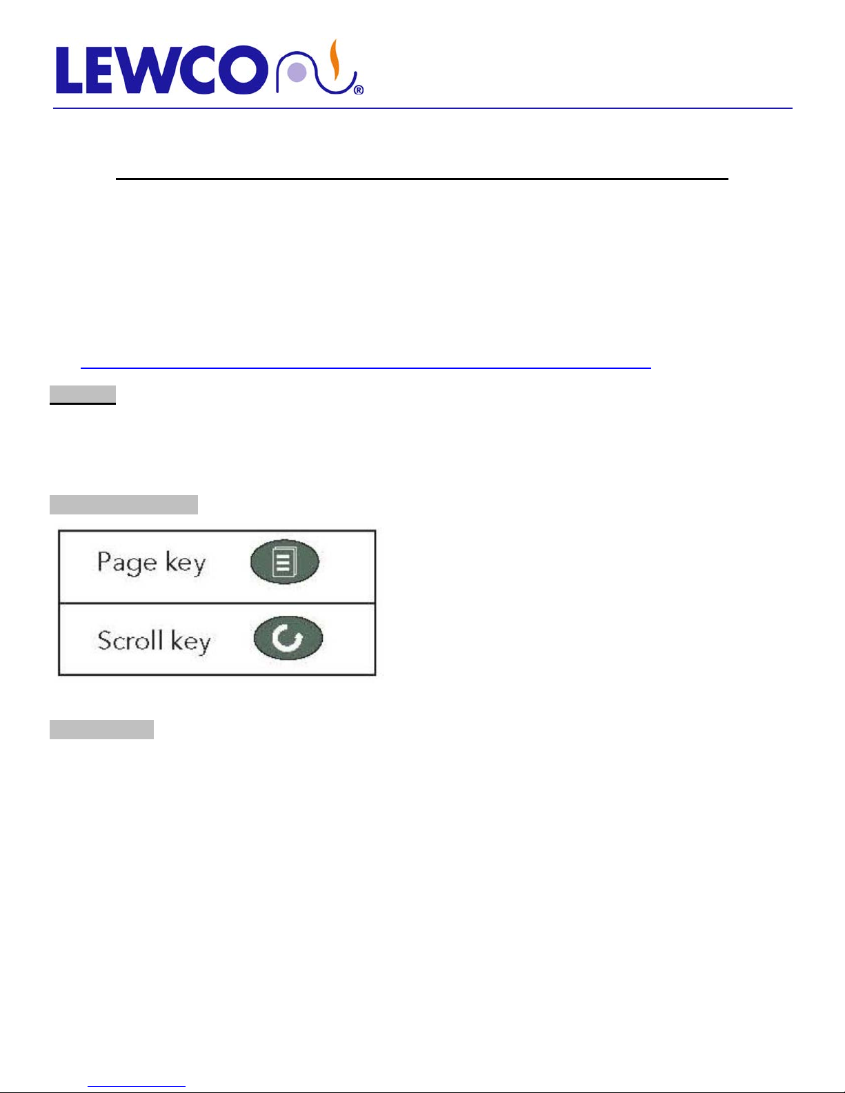
BUTTON LEGEND:
OPERATION:
If an alarm set point is exceeded or a sensor failure occurs, the alarm relays will change state. Once
the sensor fault and PV return to a safe state and have been acknowledged the relays will return to
their original state.

INDUSTRIAL OVENS
GENERAL INSTRUCTION GUIDE
EUROTHERM 2204 FM APPROVED LIMIT CONTROLLERS
ALARMS:
There are 2 FM approved alarm relays available in the 2204i, however some devices may not be configured for
both alarms. The type of alarm is also configured upon installation and cannot be changed without logging into
the configuration mode. There are 3 different options for alarm types:
1. FSH - Full Scale High
2. FSL - Full Scale Low
3. OFF- this will deactivate the alarm relay
TO ACKNOWLEDGE / RESET THE ALARM RELAY:
The alarm relay is FM approved and must be manually acknowledged. Once the process variable has
returned to a safe value and the alarm is acknowledged the relays will automatically reset. The alarm
can be acknowledged by pressing the PAGE button.
TO CHAN GE ALARM SET POINTS:
NOTE: If set point is shown in the lower display just press the UP and DOWN arrows. If it is not shown
follow the instructions below.
Press the PAGE button (1st on the left) twice. The display will show < AL LIST >
To display the type of alarm that the instrument is set for press the SCROLL button and the alarm type
will be shown in the upper display. NOTE: If the type of alarm needs to be changed see the section on
configuring alarms.
The lower display will show the present alarm set point value in engineering units. To change the set
point value use the UP or DOWN button.
NOTE: Set Limit Controller Set Point at 20
• Electric Drum Heating Cabinets: 300
• Steam Drum Heating Cabinets: 300
• High Humidity Drum Heating Cabinets: 190
°
F over maximum operating temperature.
°
F + 20° F = 320° F.
°
F + 20° F = 320° F.
°
F + 20° F = 210° F.

INDUSTRIAL OVENS
GENERAL INSTRUCTION GUIDE
EUROTHERM 2204 FM APPROVED LIMIT CONTROLLERS
CONFIGURING ALARMS:
Press the PAGE button until you see ACCS in the upper portion of display and LIST in the lower portion
Press the SCROLL button and the display will show CODE in the upper portion of the display and “0” in
the lower display. Press the UP arrow to change the “0” to the number “1”.
Press the SCROLL button and the display will show GOTO in the upper display and OPER in the lower
display.
Change OPER to CONF by pressing the UP arrow button.
Press the SCROLL button and the display will now show CONF in the upper display and “0” in the
lower.
Change the “0” to a “2” using the UP arrow
Press the PAGE button until you see AL in the upper display and CONF in the lower display.
Press the SCROLL button once and AL 1 will appear in the upper display and FSH will appear in the
lower display use the UP arrow to change this to the desired alarm type FSH, FSL, or OFF.
For alarm 2, press the SCROLL button again and the upper display will read AL 2 and use the UP
arrow to change this to the desired alarm type.
Press the PAGE button until upper display says EXIT and lower display says NO. Change the NO to
YES instrument will cycle power and reset.
TO ADJUST THE ALARM HYSTERESIS VALUE:
Hysteresis is the difference between the point at which the alarm switches ON and the point at which
it switches OFF. It is used to prevent relay chatter.
Press the PAGE button twice. The display will show < AL LIST >
Press the SCROLL button twice. The top display will read < hY > and the lower display will show the
hysteresis value in engineering units. To adjust the hysteresis value, use the UP or DOWN button; the
minimum value is 1. The hysteresis value is common to any configured alarm.

INDUSTRIAL OVENS
GENERAL INSTRUCTION GUIDE
EUROTHERM 2204 FM APPROVED LIMIT CONTROLLERS
TO CHANGE ENGINEERING UNITS (° F TO ° C):
Press the PAGE button until you see ACCS in the upper portion of display and LIST in the lower portion.
Press the SCROLL button and the display will show CODE in the upper portion of the display and “0” in
the lower display. Press the UP arrow to change the “0” to the number “1”.
Press the SCROLL button and the display will show GOTO in the upper display and OPER in the lower
display.
Change OPER to CONF by pressing the UP arrow button.
Press the SCROLL button and the display will now show CONF in the upper display and “0” in the
lower.
Change the “0” to a “2” using the UP arrow.
Press the PAGE button until you see INST in the upper display and CONF in the lower display.
Press the SCROLL button and you will see UNITS in the upper display and °F or °C in the lower display
depending on what the unit is set for. Press the UP arrow until Engineering units desired is shown.
Press the PAGE button until upper display says EXIT and lower display says NO. Change the NO to
YES instrument will cycle power and reset.

INDUSTRIAL OVENS
GENERAL INSTRUCTION GUIDE
EUROTHERM 2204 FM APPROVED LIMIT CONTROLLERS
TO CHANGE THERMOCOUPLE TYPE:
Press the page button until you see ACCS in the upper portion of display and LIST in the lower portion.
Press the SCROLL button and the display will show CODE in the upper portion of the display and “0” in
the lower display. Press the UP arrow to change the “0” to the number “1”.
Press the SCROLL button and the display will show GOTO in the upper display and OPER in the lower
display.
Change OPER to CONF by pressing the UP arrow.
Press the SCROLL button and the display will now show CONF in the upper display and “0” in the
lower.
Change the “0” to a “2” using the UP arrow.
Press the PAGE button until you see IP in the upper display and CONF in the lower display.
Press the SCROLL button until INPT appears in the upper display and the thermocouple type (LEWCO,
Inc. typically uses J) J.TC shows in the lower display.
Press UP or DOWN arrow until desired thermocouple type is shown.
Press SCROLL button again the upper display will read RNG.L for range low. The present value will be
shown in the lower display. This value can be changed by pressing the UP arrow the maximum and
minimum value is limited by the type of thermocouple selected.
Press SCROLL button again the upper display will read RNG.H for range high. The present value will
be shown in the lower display. This value can be changed by pressing the UP arrow the maximum and
minimum value is limited by the type of thermocouple selected.
NOTE: This high and low range will determine the maximum and minimum temperature for the set point
of the alarms.
Press the PAGE button until upper display says EXIT and lower display says NO. Change the NO to
YES instrument will cycle power and reset.

INDUSTRIAL OVENS
GENERAL INSTRUCTION GUIDE
EUROTHERM 2204 FM APPROVED LIMIT CONTROLLERS
TO CHANGE TEMPERATURE CONTROL RANGE:
NOTE: The range high value rnG.H should never be set higher than the maximum temperature of the
oven/drum cabinet. Doing so may cause damage to the unit. Customer assumes responsibility for any
damages caused by changing the range high limit.
Press the PAGE button until you see ACCS in the upper portion of display and LIST in the lower portion.
Press the SCROLL button and the display will show CODE in the upper portion of the display and “0” in
the lower display. Press the UP arrow to change the “0” to the number “1”.
Press the SCROLL button and the display will show GOTO in the upper display and OPER in the lower
display.
Change OPER to CONF by pressing the UP arrow.
Press the SCROLL button and the display will now show CONF in the upper display and “0” in the
lower.
Change the “0” to a “2” using the UP arrow.
Press the PAGE button until you see IP in the upper display and CONF in the lower display.
Press the SCROLL button until you see rnG.H appear in the uppder display and the value will ap pe ar
in the lower display, use the UP and DOWN arrows to change this to the desired temperature
(typically 20° over the maximum temperature of the ov e n)
Press PAGE button until upper display says EXIT and lower display says NO. Using the UP arrow
change the NO to YES instrument will cycle power and reset.
NOTE: This procedure can be repeated to change the low range rnG.L.
• This high and low range will determine the maximum and minimum temperature for the set point of the
alarms.
 Loading...